Review

Past, Present, and Future of New Applications in Utilization of Eddy Currents

by
Nestor O. Romero-Arismendi
1,
Juan C. Olivares-Galvan
2,*,
Jose L. Hernandez-Avila
2,
Rafael Escarela-Perez
2,
Victor M. Jimenez-Mondragon
2 and
Felipe Gonzalez-Montañez
2
1
Departamento de Electronica, Universidad Autonoma Metropolitana Azcapotzalco, Mexico City 02128, Mexico
2
Departamento de Energia, Universidad Autonoma Metropolitana Azcapotzalco, Mexico City 02128, Mexico
*
Author to whom correspondence should be addressed.
Technologies 2024, 12(4), 50; https://doi.org/10.3390/technologies12040050
Submission received: 8 March 2024 / Revised: 4 April 2024 / Accepted: 4 April 2024 / Published: 9 April 2024
(This article belongs to the Collection Electrical Technologies)

Abstract

:
Eddy currents are an electromagnetic phenomenon that represent an inexhaustible source of inspiration for technological innovations in the 21st century. Throughout history, these currents have been a subject of research and technological development in multiple fields. This article delves into the fascinating world of eddy currents, revealing their physical foundations and highlighting their impact on a wide range of applications, ranging from non-destructive evaluation of materials to levitation phenomena, as well as their influence on fields as diverse as medicine, the automotive industry, and aerospace. The nature of eddy currents has stimulated the imaginations of scientists and engineers, driving the creation of revolutionary technologies that are transforming our society. As we progress through this article, we will cover the main aspects of eddy currents, their practical applications, and challenges for future works.

1. Introduction

Eddy currents, alternatively referred to as Foucault currents, represent an electromagnetic phenomenon first identified by the pioneering physicist Leon Foucault during the 19th century. Foucault observed that a conductive material heats up when it is in the vicinity of a time-varying magnetic field, and he verified that this temperature increase is caused by the presence of induced currents on the surface of the material [1]. The magnitude of the induced surface eddy currents depends on the variation in the excitation magnetic field; such variations can be achieved by using a time-varying current or by varying the distance between the magnetic source and the conductor. Firstly, eddy currents are manifested by the heating of the surface of the conductive material due to ohmic losses related to the Joule effect. Beyond ohmic losses, eddy currents manifest themselves through the generation of a reaction magnetic field that interacts with the main magnetic field. According to the Lenz’s law, the magnitude of the reaction magnetic field generated by the eddy currents is opposed to the variation of the main magnetic field that generated them. Finally, Lorentz forces are produced due to the interaction between the magnetic field induced by the eddy currents and the main magnetic field.
Eddy currents are common in electrical machines made of iron alloys. Particularly, in rotating machines, they occur in any metallic component within the equipment. This encompasses transformer components (transformer tanks and ferromagnetic core) and motor components (casings or magnetic circuits of the rotor and stator). Research has demonstrated that heat losses resulting from the Joule effect on tanks and other structural elements of distribution transformers, generated by eddy currents, can amount to as much as 15% of the corresponding load losses [2]. To minimize losses in the transformer core, it is divided into a set of ferromagnetic laminations through which the magnetic flux travels. This design choice is based on the fact that the magnitude of the eddy currents is directly proportional to the square of the thickness of the laminations [3]. A reduction in stray losses can be achieved through various approaches, such as: (a) implementing electromagnetic shielding, (b) integrating stainless steel plates on the low-voltage side, and (c) investigating alternative materials such as aluminum for the manufacturing of transformer tanks. For a deeper understanding, please refer to the information described in [4]. Historically, eddy currents were viewed as undesirable due to the heat they generate in various electrical machines and other electromagnetic devices.
However, this article presents the use of the eddy current phenomenon to develop novel technologies in different areas, generating a positive impact on the world economy. First of all, the unwanted heat generated by eddy currents can be used in metallurgical treatments [5,6], welding [7], and melting furnaces [8,9]. The use of the heat produced by eddy currents has allowed this phenomenon to be applied to commercial technologies that have a wide diffusion, such as induction stoves. In these devices, energy is transferred from the wall outlet to a metal pot through an electromagnetic coupling. A high-frequency booster circuit is used in order to generate a high-frequency time-varying magnetic field. The magnetic flow induces eddy currents on the metal pot’s surface, as is described by Ampere’s and Faraday’s laws. Finally, heat is generated inside the metal pot according to the Joule heating principle [10]. Meanwhile, the magnetic field induced by eddy currents has been applied in a variety of technologies, mainly in the non-destructive evaluation of materials (NDE). In 1879, D. E. Hughes demonstrated that the induced magnetic field has some information on the chemical, physical, and electrical characteristics of the conducting material [11]. Indeed, the induced magnetic field is influenced by path variations in the superficial eddy currents caused by the presence of surface imperfections in the studied structure. These variations allow for the detection and characterization of surface defects in conductive materials. Several eddy-current-based non-destructive evaluation (EC-NDE) techniques for detecting surface imperfections of conductive materials can be found in the literature. Classical EC-NDE techniques estimate defects in metal plates using the impedance variations of the excitation coil. Authors such as Peng et al. [12] have used differential coils to detect surface cracks in aluminum plates by measuring the variations in the inductive and resistive components of the coil. However, the sensitivity of coils is much lower than the sensitivity of the current magnetic sensors, so EC-NDE techniques that use these magnetic sensors are more reliable than the classical techniques [13,14]. Giant magnetic resistance (GMR) sensors are the most popular magnetic sensors used to develop EC-NDE systems [13,15,16]. The magnetic fields induced by eddy currents can also be used in medical applications. The induced magnetic fields can be used to solve bioelectromagnetic problems [17]. Eddy currents find specific applications in the bio-electromagnetic study of the human brain, as documented in references [18,19,20]. Different efforts have been made in order to computationally obtain 3D models of the human brain using eddy current simulations; in [21], the authors analyzed three coils with different geometries in order to determine the optimal geometry for transcranial magnetic stimulation. In addition, 2D images of the brain have been obtained using experimental impedance tomography based on eddy currents. Even eddy-current-based cancer treatments have been proposed [22], although there are no subsequent studies to support this proposal.
The Lorentz forces resulting from the interaction between the induced magnetic field and the main field can be used for different applications. These Lorentz forces could have two components: a normal one, which can be used as a levitation force, and a longitudinal one, which can be used as break force. The levitation force is widely used to develop Maglev trains based on the phenomenon of electrodynamic suspension (EDS) [23,24,25,26]. Maglev–EDS trains carry permanent magnets or superconducting coils on board, and these trains move on rails of conductive sheets. The displacement of the wagons induces eddy currents in the rail, which generate a magnetic field opposite to the field generated by the onboard magnetic field source. The train levitates due to the repulsive force generated by the interaction between the magnetic field induced in the rail and the magnetic field on board. However, this technology requires an initial movement of the wagon to generate a minimum levitation force, that is, it requires a minimum speed to induce the currents necessary for levitation. Eddy current braking (ECB) is linked to the Lorentz force resulting from the interaction between the induced and inductor magnetic fields [27,28,29,30,31]. Instead of using conventional mechanical brakes, ECB induces eddy currents in a metal disc so that a magnetic field is induced which generates a force opposite to the rotational movement of the disc. Frictional wear is reduced and braking performance at high speeds is increased by using an ECB.
In addition to applications that directly use eddy currents, different studies [32,33,34,35] have shown that some materials exhibit a high-frequency diamagnetic response due to the reverse magnetic field induced by them. These investigations demonstrate that diamagnetic materials have great potential to be used in electromagnetic shielding and attenuation systems. Fan et al. [32] proposed the development of filtered nickel/rutile cermets that have diamagnetic behavior at high frequencies. Currently, the influence of eddy currents on the magnetic properties of some materials has been taken advantage of to develop metacomposites and metamaterials that can improve the design of shielding. Fan et al. [34] proposed nanocomposites based on biomass-derived ferrous magnetic carbon that can be used for the development of metacomposites in an environmentally friendly manner. The results show that the nanocomposites have absorption capacities from 13.0 to 18.0 GHz. Qu et al. [36] proposed a polyaniline/nickel metacomposite which can be used in practical applications in shielding and new electromagnetic sensors. Cheng et al. [35] proposed a method for the development of metacomposites of nickel/yttrium and iron granules. The results showed a large increase in electromagnetic shielding when this metacomposite was used. However, this article will not delve into applications with metamaterials, but will focus on applications that directly apply the eddy current phenomenon.
Although several review articles have been published that compile advances and research in eddy-current-based technologies [11,29,37,38], they are only focused on specific applications. After an exhaustive search, we found a review article that covers a wide spectrum of applications that depend on eddy currents; unfortunately, its publication dates back more than three decades [39]. In this context, this article aims to offer an approach to the theory and current technological developments that are based on eddy currents. Although the eddy current phenomenon has been the basis of numerous applications, such as induction stoves, induction furnaces, and metal detectors, this article will focus on five main areas: non-destructive evaluation of materials, magnetic levitation trains, inductive braking systems, applications in medicine, and electromagnetic take-off technologies.
This article is organized as follows: Section 2 presents a theoretical introduction to the eddy currents, and Section 3, Section 4, Section 5, Section 6 and Section 7 present some novel applications based on eddy currents in the areas of non-destructive evaluation, magnetic levitation trains, braking systems, medicine, and electromagnetic take-offs, respectively. Finally, Section 8 presents the conclusions, overview, and prospects of eddy-current-based technologies.

2. Theory of Eddy Currents

Eddy currents are an electromagnetic phenomenon that can be described by Faraday’s law, shown in (1):
× E = B t
where E and B correspond to the electric and magnetic field, respectively. According to (1), it can be noted that a time-varying magnetic flux induces a voltage; when the trajectory closes, this voltage generates an electric current. Particularly, a voltage induced on the surface of the solid conductive material generates currents along circular paths, i.e., eddy currents.
It is possible to determine the induced magnetic field and Lorentz force at a given point by expressing them in terms of the eddy current density using Maxwell’s equation. In electromagnetic problems, the current density J , the magnetic flux density B , and the electric field E   are related as follows:
  ·   J = 0
B   = μ r   H
J =   σ r E
where μ r corresponds to the magnetic permeability of the medium and σ r corresponds to the electric conductivity of the conductive material.
However, to analyze the distribution of eddy currents on the surface of the material, B and E can be also expressed in terms of magnetic vector potential A and electric scalar potential Φ, respectively, as:
  ×   A   =   B
E = Φ   A t
By substituting (5) and (6) into the relationships presented in (3) and (4), Ampere’s Law can be represented as follows:
  ×   1 μ     ×   A = σ     Φ +   A t = J
Considering the current density as:
J = J e   + J s  
where J e   represents the eddy current density and J s   the extermally impressed source current density.
Considering a homogeneous medium with constant permeability, (7) can be reformulated as follows:
  · A 2 A = μ σ   Φ +   A t
Taking into account (8), the right-side term of (9) can be separated into two terms. The first term, σ Φ , represents J s   , whereas the second term, μ σ A t , represents J e   on the surface of the material.
Applying the Lorentz gauge condition, · A + 1 c Φ t = 0 , to (9), the following expression is obtained:
2 A = μ σ A t = J e  
which is used to solve eddy current problems. The general solution of (10) depends on several factors, such as the geometry of the problem and the coordinate system. But the possible solutions of the differential equations must meet the following boundary conditions:
n × E 1 E 2 = 0
n × H 1 H 2 = K
n × B 1 B 2 = 0
where n is the vector normal to the interface between the two media and K is the current density vector in the border of the interface between the two media. B n ,     H n , and E n correspond to the magnetic flux density, magnetic field strength, and the electric field in the n-media, respectively.

3. Non-Destructive Evaluation

Non-destructive evaluation is the main industrial application of eddy currents. It can be observed in Figure 1 that, due to the presence of a near-side crack in a conductive material, the excitation magnetic field does not affect it uniformly, so the eddy current’s trajectory is affected. Such trajectory variations cause distortions in the induced magnetic field. It has been proven that surface [40,41,42] and subsurface [43,44,45] cracks can be detected and characterized by measuring the distortions of the induced magnetic field.
In this section, some significant advances of eddy-current-based NDE (EC-NDE) systems are described. Table 1 shows some hardware of EC-NDE systems presented in the literature. O. Postolache et al. [46] proposed a GMR-based probe composed of a rectangular coil to generate the excitation magnetic field and a GMR sensor array to measure variations in magnetic field density. However, the proposed probe may present limitations in terms of versatility for applications that require rapid on-site estimates. The efficiency of this configuration for different contexts or environments could be questioned. Hamia et al. [38] implemented a lock-in amplifier to acquire the phase components of the GMR output. The results reveal that surface defects in aluminum plates could be characterized using these signal components. However, the implementation of lock-in amplifiers is complex, and it could be a potential limitation in terms of cost, efficiency, or measurement accuracy. P. Gao et al. [47] showed that it would be possible to characterize the geometric characteristics of surface cracks in aluminum plates by analyzing the magnitude and phase of the GMR output voltage. However, the implementation and conditioning circuit of these EC-NDE probes are complex. Espina et al. [48,49,50] proposed a GMR-based probe composed of a GMR sensor together with an excitation coil in pancake-like configuration to improve the sensitivity compared to classic EC probes. The authors proposed expressions for the estimation of the width (w) and depth (d) of the defect using only two parameters extracted from the GMR-based probe [48]. However, the proposed analytical expressions are valid only for cracks within a reduced range. EC-NDE, in addition to being one of the most used techniques to detect defects in aluminum structures, can also be extended to a wide variety of metals. Xia et al. [51] proposed a method to estimate the depth of defects in metallic discs. The proposed analytical model allows the depth and edges of defects to be identified not only in aluminum, but also in stainless steel discs. However, this system requires monitoring the liftoff between the probe and the disk to obtain accurate results.
EC-NDE systems not only detect the geometric features of metals, but can be used to detect and estimate different magnitudes of the material. Wolter et al. [33] presented a combination of NDE methods that allows the microstructure of ferromagnetic metals to be analyzed. It obtains a 2D image of the material structure by using the proposed system. The authors demonstrated that it is possible to detect plastic elongation and stresses in a material by monitoring the obtained images of the material’s microstructure. However, using the proposed system, it can only be identified that an elongation force exists, but not the place where is applied. Wang et al. [52] proposed a novel mutual inductance sensor to acquire high-frequency eddy currents (HFEC) to characterize tensile stress in electroplated nickel coatings. The experimental results demonstrated that the frequency component of HFEC varies parabolically with respect to tensile stress and coating thickness. The analytical expressions were obtained through a polynomial fit, and these expressions allowed the tensile stress to be predicted. However, the set of samples used was small, so it will be necessary to contrast the results obtained in a larger set of samples. EC-NDE systems can be combined with other NDE techniques to improve their performance. Wertz et al. [54] proposed a system that fuses EC-NDE data with data acquired through electron backscatter diffraction to characterize microtexture regions in titanium alloys. The authors demonstrated that the use of fused data eliminates the limitation in the spatial resolution of EC-NDE systems. This limitation prevents EC-NDE systems from only being used to observe features smaller than 350 μm in isotropic and homogeneous materials. However, the results presented in [53] were obtained in a simulation, so it is necessary that the method be applied to experimental data.
It is important to mention that it has recently been discovered that EC-NDE systems can also be applied through the characterization of dielectric materials. Matsunaga et al. [54] presented an electrical circuit model for EC-NDE based on an impedance plane diagram obtained by solving the Ampere–Maxwell equations. The proposed model takes into account both the conductivity and the permittivity of the material. However, there is a long way to go before implementing EC-NDE systems in dielectric materials; it is necessary to contrast the theoretical results obtained with experimental values.
EC-NDE is a fast and reliable technique for detecting defects in conductive materials. However, in real applications, the aim of the EC-NDE is to classify and characterize the geometric parameters of surface defects such as width, depth, and angle of orientation. Table 2 presents the methods to classify these geometrical parameters which have been proposed in literature. It is possible to identify two main techniques to estimate the geometrical features of cracks: using image processing and using machine learning and pattern recognition algorithms, such as support vector machines and neural networks. In image processing techniques, a two-dimensional image of the surface of the inspected material is obtained by transforming the magnetic field density at each position obtained with the EC-NDE probe into a pixel intensity value. Postolache et al. [46,55] used an adaptive Wiener filter to identify the background and remove it; then, the image of each GMR sensor of the array was merged. Pasadas et al. [56] used 2-D filtering techniques and spectral analysis to segment and detect the edges of the surface defects. Thus, it is possible to estimate the geometrical characteristics of the surface defect by using image processing. However, all the aforementioned techniques require a complex mechanical system to perform the scanning, which would increase production and maintenance costs in real applications. Currently, it has been decided to implement techniques that use machine learning to reduce these shortcomings. Wrzuszczak et al. [57] showed that the geometric characteristics of a superficial defect can be obtained by applying neural networks to the EC-NDE system. The depth and width of surface defects are estimated by mapping the area around the defect to obtain the amplitude, phase, and frequency of the measured signal. The parameters obtained from the system output signal are used as input values for a radial basis function network to obtain the dimensions of the defect. From there, Peng et al. [58] and Rosado et al. [59,60] proposed neural networks as regression algorithms to obtain geometric features of defects. However, Bernieri et al. [61] carried out a comparison between the performance of artificial neural networks (ANNs) and support vector machines (SVMs), showing that the classification performance was higher using SVM than ANN. Therefore, Chelabi et al. [62] proposed least-squares support vector machines (LS-SVMs) and polynomial functions to correlate the output voltage of the GMR sensor with the defect geometric characteristics. The LV-SVM proposed had good accuracy, and it was faster than the classic SVM. However, these techniques require obtaining an output vector of the GMR sensor with a large amount of data, which would increase the computational costs of the system. Romero et al. evidenced in [63] the existence of a single pair (DV, DX) corresponding to a particular defect in terms of width, depth, and angle of orientation. This makes it possible to classify two geometric characteristics of defects using only two parameters instead of using a vector with multiple components, as was the case in the previously mentioned methods. Using only two parameters to classify the geometric features could improve the performance of the EC-NDE for practical applications. However, the authors mention that this method can only be used if one of the parameters must be known.
So far, different novel EC-NDE systems have been presented; however, these are mainly implemented in laboratory conditions, and temperature is not taken into account. The aim of the EC-NDE system is to be able to monitor the conditions of metal structures on site. However, the structures that require constant monitoring commonly operate in high-temperature conditions, which presents great challenges for EC-NDE systems. For instance, ultra-supercritical thermal-power plants require analyzing the degradation of heating tubes after prolonged operation. Sun et al. [64] proposed an EC-NDE system based on a superconducting quantum interference device (SQUID) with high sensitivity. The proposed system can be used to perform a quick on-site inspection of the characteristics of the boiler tubes of a thermal power plant. However, to carry out the inspection, it is necessary for the tubes to reach room temperature. Therefore, several efforts have been made to find techniques that allow inspections to be carried out without reaching room temperature. Currently, it has been considered to implement hybrid systems in order to reduce the effects of high temperatures. Santos et al. [65] proposed an automated NDE system for the inspection of tubes operating at temperatures up to 200 °C. The authors combined two NDE techniques, an EC-NDE and an ultrasound- based NDE. Each of the methods has specific approaches to avoid the influence of high temperatures. The ultrasound-based system focused on searching for volumetric defects, while the EC-NDE is focused on searching for near-side cracks. The results showed that it is possible to perform measurements with this hybrid system in temperature conditions up to 300 °C. Wang et al. [66] proposed a hybrid online monitoring method for defect inspection in high-temperature environments. The proposed method is a combination of EC-NDE and an electromagnetic acoustic transducer. The hybrid system uses two different channels to transmit each signal. The results showed that the proposed hybrid system can monitor surface and inner defects under conditions up to 300 °C. Despite great advances, it is still necessary to develop EC-NDE systems able to operate in more extreme environments, that is, temperatures above 300 °C.

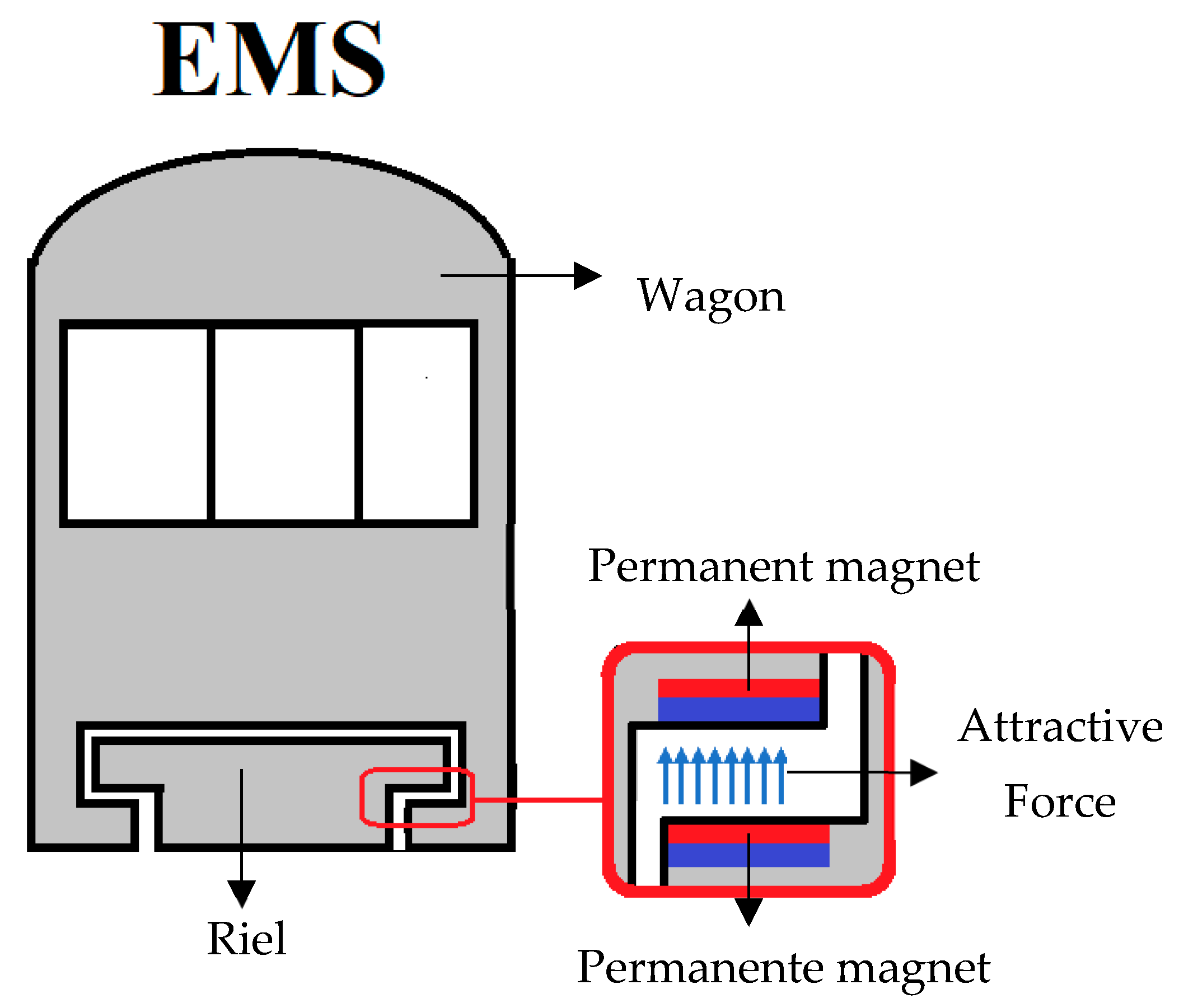
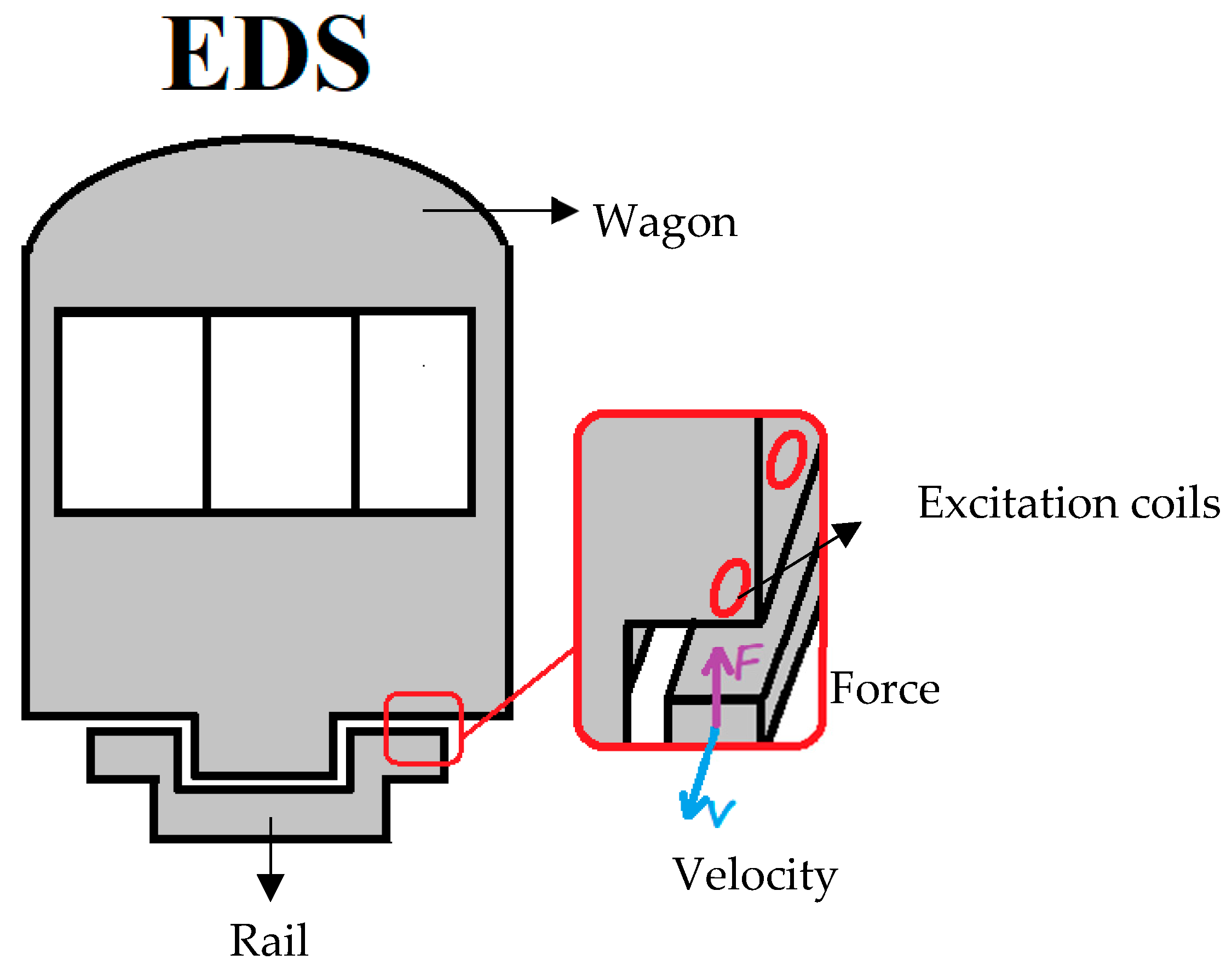
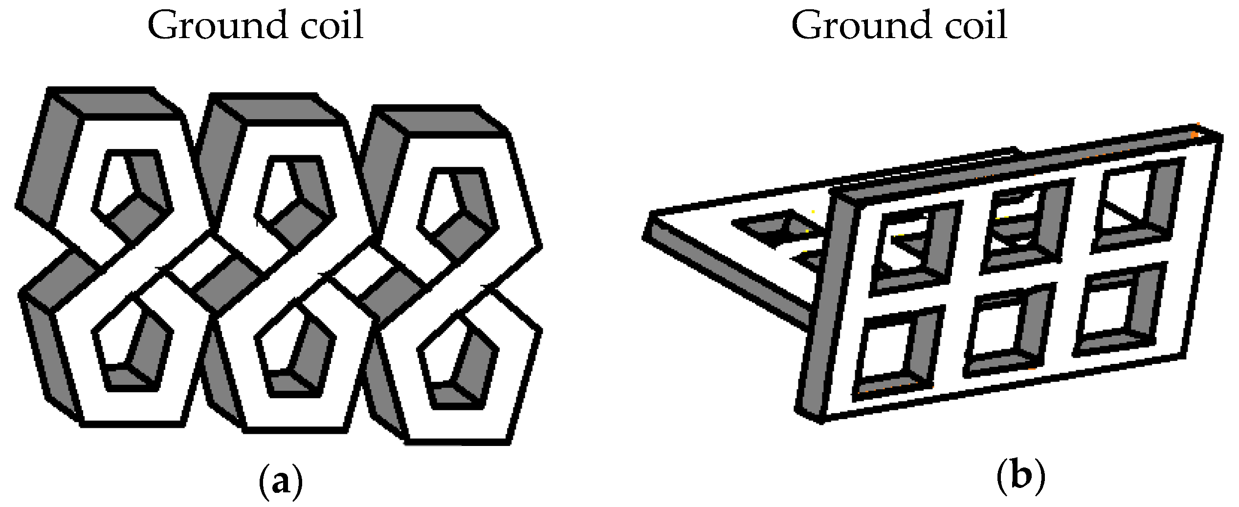
4. Maglev Applications

It has been demonstrated that there is at least one unstable axis in an electromagnetic levitation system (EMS) using static magnetic fields [67], because a charge cannot be maintained in a stable mechanical equilibrium solely by the electrostatic interaction of the charges, as is indicated by Earnshaw’s theorem. A particle must return to its previous position in the face of any disturbance to remain in equilibrium; this means that all the field lines around the particle must point towards the equilibrium point, that is, the field divergence at the equilibrium point must be negative. However, this would violate Gauss’s law, which states that the divergence of any possible electric force field is zero in free space. The normal axis is considered as the unstable axis in attractive magnetic levitation; meanwhile, the X and Y axes are unstable in repulsive magnetic levitation. There are few magnetic levitation systems that use permanent magnets due to the aforementioned axis instability. Figure 2 shows the diagram of an electromagnetic suspension (EMS) system. The EMS system is commonly composed of a series of permanent magnets with the north pole and south pole facing each other. This configuration generates an attractive force between the rails and the wagon; however, the effects of eddy currents under high-speed conditions must be considered. Therefore, it is necessary to carry out precise control of the gap of the magnets in order to reduce the instability [68]. It is possible to generate a repulsive magnetic force using EMS systems by facing the positive poles of two magnets. However, this configuration is laterally unstable due to the destabilizing forces acting on the sides. The instability in EMS systems can be avoided by considering time-varying magnetic fields. Therefore, one magnet is replaced by an air-core coil so that the repulsive force can be easily adjusted by changing the electromagnet current. This magnet–electromagnet configuration, known as electrodynamic suspension (EDS), is the basis of several magnetic levitation systems. The main application of magnetic levitation systems is high-speed trains (Maglev), which reach speeds greater than 200 km per hour.
A diagram of an EDS is presented in Figure 3. This type of Maglev takes advantage of the movement of the vehicle to induce currents that produce the repulsive and guiding forces. It is important to mention that these Maglev systems require a threshold velocity. In addition to the inherent stability, electrodynamic Maglev systems have a higher tolerance of the vertical position of the magnet [26].
In [26], the relation of the interaction between both magnetic fluxes produced by different configurations of on-board permanent magnets and ground coil is obtained. It has been compared the ladder-on-box-beam approach and the “Modified Null Flux” configuration shown in Figure 4. With the “Modified Null Flux” configuration of a set of vertical eighth-shape coils attached to the guide wall, this set generates a magnetic field for both guidance and suspension. On the other hand, the ladder-on-box-beam approach requires two sets of square coils, one vertical and one horizontal. The vertical set is used to generate the guiding magnetic field, while the horizontal network generates the suspension magnetic field. It is possible to calculate, for each geometry, the current and forces on the coils as a function, as well as the speed of the train, from the proposed relations. Studies [24,25,69] have compared the forces and currents obtained using these analytical expressions with the experimental values measured on test tracks. The results show that the threshold speed to suspend a 2364 kg wagon with a commercial coil configuration is 12 m per second, while the tests indicate that the threshold speed is 11.2 m per second. Therefore, it possible to determine the behavior of different geometric configurations of coils to be implemented in EDS systems by applying the obtained expression so that different configurations of electrodynamic suspension systems can be designed. However, there are still many challenges to be faced, especially in the development of a cooling system for superconducting coils [69]. In addition, it is planned to design and implement faster vehicles for longer distances.

5. Inductive Braking Systems

Conventional mechanical brakes are the most widely used braking mechanisms in conventional cars; however, they have several disadvantages, such as slow braking time, friction wear, and low performance at high speeds [28]. Eddy-current-based braking (ECB) systems are an alternative to conventional brakes.
Figure 5 shows the basic diagram of an ECB braking system. An ECB system is mainly composed of a rotating metal disc attached to the tire and an electromagnet. An eddy current is induced in the rotating metal disc due to the magnetic field produced by an electromagnet. The induced eddy currents generate a magnetic field, and the interaction between the field generated by the currents and the field generated by the electromagnet induces a force opposite to the disk rotation. ECB braking systems have a few parameters that influence their performance, such as the electrical conductivity of the disk, the gap between the coil and the magnet, the magnetic properties of the conductor, as well as the angular speed of the disk. These parameters must be considered in such a way as to achieve optimal braking performance in ECB systems [29].
Li et al. [29] proposed a novel ECB braking system by analyzing the influence of air gap, disk width, and disc angular velocity. The authors proposed a theoretical model and carried out a simulation in order to obtain the design parameters of the system, and the implemented simulation also allowed for the prediction of its performance. The results showed that, by implementing an ECB system with the obtained parameters, it is possible to break an object with a linear movement speed less than 20 m/s. An experimental ECB system was implemented, and the performance was congruent with the results obtained from the simulation. Putra et al. [31] modeled an axial ECB system and used a FEM simulation to find an empirical relation between the braking torque and the air gap. The modeled ECB braking system was composed of a single disc and a semi-permanent magnet. The authors found that the performance of the ECB was higher as the gap between the magnet and the disk was reduced. In addition, the authors indicated that the number of turns of the coil should be increased to improve the performance of the ECB. The results showed that the best performance was obtained when a 0.5 mm air gap and a 360-turn coil were used. However, as there are time-varying magnetic fields interacting with metallic materials, the skin effect must be considered. Cho et al. [27] used simulations to obtain an equation that related the braking force to the depth of penetration of the eddy currents. The identified relationship indicated that, in discs composed of low-conductivity metallic materials, the system achieved greater braking torque at higher speeds. Therefore, the braking performance improves as the conductivity of the coating material increases. It is important to mention that it has been proven that the braking force depends on the temperature of the ECB system [30] due to the Joule effect. However, systems are still being developed that allow a constant temperature to be maintained in order to implement robust braking systems.
ECB braking systems increase their performance at high speeds; therefore, they are frequently used in high-speed trains [70]. However, ECB systems must be used in conjunction with conventional brakes for low-speed braking. ECB systems in trains do not require a rotating disc, as eddy currents are induced in the rails to generate braking force. However, there is still a need to reduce the heating of the rails. ECB systems have also been implemented in commercial mountain trucks to prevent heating failures on long descents [71]. Braking time is reduced from 300 to 400 milliseconds by using an ECB system instead of conventional brakes [71]. However, ECB braking systems have the disadvantage of having a low torque per unit volume, which makes them, so far, difficult to implement in passenger transport cars. ECB systems are also used in damping systems [72] to prevent high-speed aircraft that have aborted takeoff from skidding off the runway [73,74].
In addition to the advantages previously mentioned, ECB systems have great potential to be used as regenerative braking systems. Regenerative braking (RGB) systems are composed of a drive motor, a hybrid ECB–mechanical braking system, a battery, and a controller. The motor transforms the kinetic energy of the vehicle’s braking into electrical energy. The recovered energy is transferred to the engine or ECB system to improve its performance while the car is moving [75]. Guneser et al. [76] obtained a mathematical model of a regenerative ECB system and carried out a simulation in MATLAB/Simulink. The results showed that the ECB system was effective in terms of reducing vehicle speed. However, the simulations did not consider aspects such as the dimensions of the vehicle, the type of terrain, or mechanical losses. Li et al. [77] presented a methodology for the design of RGB systems; then, the authors verified their design with simulations. The results show that the proposed system can generate the electrical energy necessary to satisfy the energy demand of the ECB system to generate the required braking torque. Miao et al. [75] proposed a control method for the speed of a vehicle traveling downhill using an RGB system. When the speed was high, the energy recovered by the RGB system was not enough to generate the required deceleration torque; therefore, an external power supply was required. Once the speed had been reduced, the ECB stopped drawing energy from the vehicle, as it was able to provide the energy needed to maintain a constant speed. The obtained results indicate that, in order to maintain a speed of 120 km/h on a long downhill trajectory, the RGB system only requires an external power supply for 2 s.

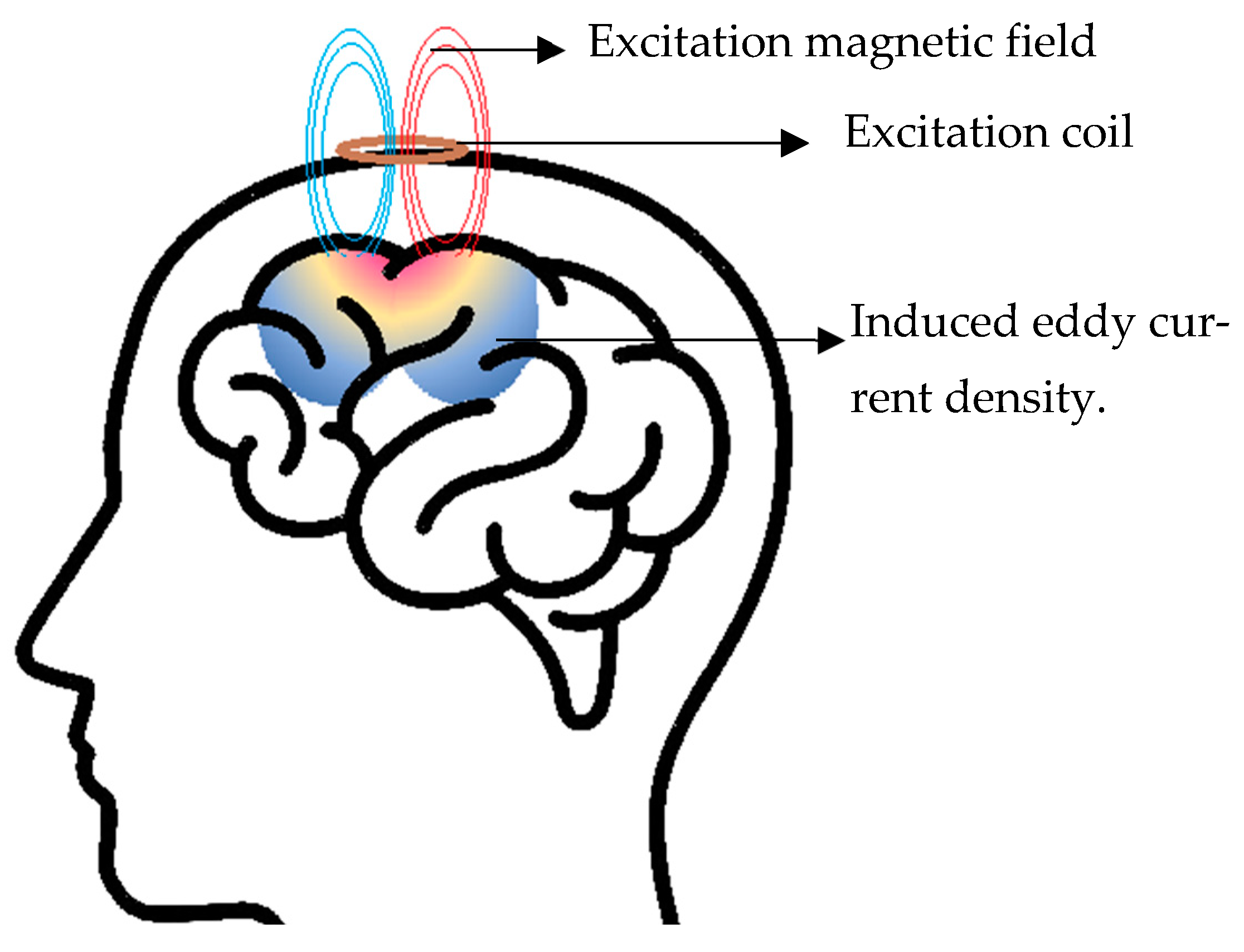
6. Medical Applications

It has been shown that eddy currents generate stimuli and localized heat in biological tissues. Therefore, eddy currents are a promising tool in medical applications involving neuromuscular stimulation. Next, some applications of eddy currents in medical therapies are explored, highlighting their potential to improve the quality of life of patients and revolutionize clinical practice.
Electroconvulsive therapy (ECT) is a treatment for mental illnesses such as depression, anxiety, etc. ECT involves the electrical stimulation of certain brain areas to treat mental illness [78]. However, ECT presents a great risk to patients because it requires invasive procedures [79]. At present, there is no consensus on the optimal stimulus intensity or the ideal current distribution within the brain. Therefore, it is crucial to develop and characterize less invasive therapies. Transcranial magnetic stimulation (TMS) is a technique that stimulate sections of the brain using eddy currents generated by pulsed magnetic fields [78]. TMS has great potential to develop therapies that are less invasive than ECT. In Figure 6, a diagram of an EMT therapy is presented. It consists of a coil located on the patient’s scalp. The coil generates a pulsed magnetic field which induces eddy currents in certain area of the brain. The eddy currents induce action potentials in neurons so that they can evoke activations in a specific region of the brain.
The distributions of eddy currents in the brain by TMS have been determined by using numerical simulations [80]. Sekino et al. [78] observed that the current distributions in the brain using TMS depend on the characteristics of the coil used. The results showed that the neurons present in the cerebellum could be activated by inducing a magnetic field of 0.56 T. Currently, TMS has the potential to be applied to the diagnosis and treatment of types of neuronal diseases, such as depression [81,82,83], stroke [84,85], multiple sclerosis [86,87,88], and limb paralysis [89,90], without the disadvantages of electrical stimulation therapies. Eddy currents not only have been used in the development of new therapies, but also complement currently available ones. This phenomenon is used, for example, to recharge implanted medical devices without having to remove them in order to increase their useful lifetimes. Sato et al. [91] modeled a wireless power transmission (WPT) method based on eddy currents to recharge a titanium-coated pacemaker. The power transmission efficiency of the proposed WTP is between 36% and 52%. Theoretical modeling and safety simulations of WTP pacemakers has been carried out [92,93,94]. The results show that WTP pacemakers are safe to be implemented in patients with cardiovascular diseases. However, simulated results still need to be verified with results in patients. In addition, it is necessary to follow up with patients through the years in order to rule out new alterations caused by stimulation with magnetic fields.
Eddy currents are used not only in the advancement of novel therapies, but also in the measurement of biomedical parameters. Eddy-current-based sensors (EC sensors) are not limited to non-destructive evaluation applications. An EC sensor consist of a coil that generates a magnetic field to induce eddy currents in a metal structure. EC sensors are low-cost and reliable, and can operate in a wide range of environmental conditions. Stubbe et al. [20] implemented a technique to estimate the cranial rhythmic impulse (CRI) using EC sensors. CRI is an important concept in osteopathic medicine that refers to patient health. The CRI measurement system consists of aluminum foil located on the left frontal bone and a coil facing the patient’s skull without being in physical contact with the aluminum foil, as shown in Figure 7. The eddy-current-based measurement system is more sensitive compared to other techniques, such as Eco-Doppler [20].
Eddy currents are also used in the development of electrical impedance tomography (EIT) systems. The EIT system allows the variations in the electrical properties of a biological material to be visualized to obtain an image of some tissues of the human body [95]. Traditional EIT systems require a considerable number of electrodes in the patient’s body to obtain a good-quality image. However, Ambia et al. [19] proposed an eddy-current-based EIT system to reduce the number of electrodes. The proposed system allows the distribution of internal resistivity and the shape of a phantom that emulates a biological tissue to be visualized. However, the data acquisition time of this system is around 40 min, so it will be required to propose new acquisition methods in order to reduce this time.

7. Electromagnetic Launching

Electromagnetic launch (EML) technologies allow an object to be accelerated to a very high speed by converting electromagnetic energy into kinetic energy in a very short time lapse. EML systems are characterized by short acceleration times and high-output kinetic energy. EML technologies are mainly implemented in military applications, especially to develop weapons systems. In the induction coil launcher, there is no physical contact between the propeller coil and the projectile, resulting in a significant reduction in friction losses [96,97]. This EML technology allows projectiles with larger caliber and greater mass to be fired [97,98,99,100]. Beyond military applications, EML systems could be used to provide fuel to space platforms in the future. However, the magnetic coupling between the stator and the rotor is weak in EML technologies. In addition, the launch efficiency obtained in current EML is low compared to other launching methods, especially chemical launching [97,99].

8. Overview and Outlook

Considerable efforts have now been devoted to applying the phenomenon of eddy currents in new technologies. These advances show great potential in areas such as transportation, medicine, industry, satellite launches, and high-speed Maglev trains. The purpose of this article is to highlight the efforts of researchers and academics in the development of technologies based on eddy currents in order to advance the proposed lines of research. The numerous developments presented aim to change the common perceptions that readers have about eddy currents, as they are often associated only with unwanted losses.
In this article, a wide variety of technologies with a great vision of the future have been presented. However, the technologies presented in this article are in either the development or improvement phases. Thus, there is a broad panorama of research in this field of technologies based on eddy currents, since they still face a series of challenges. For example, it is desired to reduce the hardware complexity of EC-NDE systems in order to reduce mechanical components and facilitate portability for on-site testing. Furthermore, the sensitivity of the EC-NDE system for small crack dimensions is expected to increase through the development of eddy-current-based probes. Great efforts have been made to implement high-precision techniques to estimate the geometric characteristics of unknown cracks in metallic structures using NDE systems. However, more robust and computationally efficient algorithms are required that allow for the accurate estimation of these characteristics. It can be seen in this article that the phenomenon of eddy currents has had a great impact on the development of high-speed Maglev trains. However, there is still ample room for improvement: for example, the development of better electromagnetic couplings between rails and wagons and the development of superconducting electromagnets that have better thermal performance. Furthermore, design methodologies of ECB systems have been presented that allow the appropriate construction characteristics that increase braking torque and speed to be selected; however, there is still a long way to go to bring these to mass commercial diffusion. Currently, studies have begun on coordinated mechanical inductive hybrid braking systems that improve the characteristics of each individual system and minimize their respective shortcomings. The aim of hybrid brakes is to reduce frictional wear, to increase the minimum braking speed, and to maintain a constant torque per unit volume over a range of speeds. On the other hand, there are a large number of medical therapies based on eddy currents beyond those discussed in this article; however, some presented results are based on electromagnetic simulations, which underlines the need to take these investigations a step further with tests in patients or real tissues to validate these results.
In short, there is ample scope for further research into eddy-current-based technologies that can offer tangible benefits to society. This article motivates the reader to think that not only can the phenomenon of eddy currents be utilized in the applications presented previously, but there are still many applications where the heating, magnetic field variations, and forces caused by eddy currents could be explored.

Author Contributions

Conceptualization: J.C.O.-G. and N.O.R.-A.; resources: J.C.O.-G., F.G.-M., V.M.J.-M., R.E.-P. and J.L.H.-A.; writing—original draft: N.O.R.-A. and J.C.O.-G.; writing—review and editing: J.C.O.-G., N.O.R.-A., F.G.-M., R.E.-P., V.M.J.-M. and J.L.H.-A.; project administration: J.C.O.-G. and R.E.-P.; funding acquisition: J.C.O.-G., F.G.-M., R.E.-P., V.M.J.-M. and J.L.H.-A. All authors have read and agreed to the published version of the manuscript.

Funding

The authors are grateful for the financial support provided by Consejo Nacional de Humanidades, Ciencias y tecnología (Conahcyt).

Data Availability Statement

No new data were created or analyzed in this study. Data sharing is not applicable to this article.

Conflicts of Interest

The authors declare no conflicts of interest.

References

  1. Foucault, L. Recueil Des Travaux Scientifiques de Léon Foucault; Bibliothèques de l’Université de Strasbourg, Ed.; Gauthier-Villars: Paris, France, 1878. [Google Scholar]
  2. Olivares, J.C.; Cañedo, J.; Moreno, P.; Driesen, J.; Escarela, R.; Palanivasagam, S. Experimental Study to Reduce the Distribution-Transformers Stray Losses Using Electromagnetic Shields. Electr. Power Syst. Res. 2002, 63, 1–7. [Google Scholar] [CrossRef]
  3. Olivares-Galvan, J.C.; Georgilakis, P.S.; Campero-Littlewood, E.; Escarela-Perez, R. Core Lamination Selection for Distribution Transformers Based on Sensitivity Analysis. Electr. Eng. 2013, 95, 33–42. [Google Scholar] [CrossRef]
  4. Olivares-Galván, J.C.; Georgilakis, P.S.; Ocon-Valdez, R. A Review of Transformer Losses. Electr. Power Compon. Syst. 2009, 37, 1046–1062. [Google Scholar] [CrossRef]
  5. Mishra, A.; Bag, S.; Pal, S. Induction Heating in Sustainable Manufacturing and Material Processing Technologies—A State of the Art Literature Review. In Encyclopedia of Renewable and Sustainable Materials; Elsevier: Amsterdam, The Netherlands, 2020; pp. 343–357. [Google Scholar]
  6. Lucia, Q.; Sarnago, H.; Acero, J.; Carretero, C.; Burdio, J.M. Induction Heating Cookers: A Path Towards Decarbonization Using Energy Saving Cookers. In Proceedings of the 2022 International Power Electronics Conference (IPEC-Himeji 2022- ECCE Asia), Himeji, Japan, 15–19 May 2022; IEEE: Piscataway, NJ, USA, 2022; pp. 1435–1439. [Google Scholar]
  7. Dietrich, A.; Nacke, B. Numerical Investigation of Effects on Blanks for Press Hardening Process during Longitudinal Flux Heating. IOP Conf. Ser. Mater. Sci. Eng. 2018, 355, 012014. [Google Scholar] [CrossRef]
  8. Fedin, M.A.; Kuvaldin, A.B.; Lepeshkin, A.R.; Kondrashov, S.S.; Fedina, S.A.; Zhmurko, I.E. An Integrated Approach to the Mathematical Description of Induction Heating Installations Using Information Technologies. In Proceedings of the 2022 VI International Conference on Information Technologies in Engineering Education (Inforino), Moscow, Russia, 12–15 April 2022; IEEE: Piscataway, NJ, USA, 2022; pp. 1–4. [Google Scholar]
  9. Desisa, D. Numerical Modeling of Induction Heating Process Control. In Proceedings of the 2022 22nd International Scientific Conference on Electric Power Engineering (EPE), Kouty nad Desnou, Czech Republic, 8–10 June 2022; IEEE: Piscataway, NJ, USA, 2022; pp. 1–6. [Google Scholar]
  10. Chacon-Troya, D.P.; Quezada, J.; Espinoza, C. Development and Implementation of a Smart Induction Stove. In Proceedings of the 2017 Brazilian Power Electronics Conference (COBEP), Juiz de Fora, Brazil, 19–22 November 2017; IEEE: Piscataway, NJ, USA, 2017; pp. 1–5. [Google Scholar]
  11. Upda, S.; Upda, L. Eddy Currente Testing—Are We at the Limit? In Proceedings of the 16th World Conference on NDT, Montreal, QC, Canada, 30 August–3 September 2004. [Google Scholar]
  12. Peng, X.; Jun, H. A New Eddy Current Sensor Composed of Three Circumferential Gradient Winding Coils. In Proceedings of the 2013 Seventh International Conference on Sensing Technology (ICST), Wellington, New Zealand, 3–5 December 2013; pp. 912–915. [Google Scholar] [CrossRef]
  13. García-Martín, J.; Gómez-Gil, J.; Vázquez-Sánchez, E. Non-Destructive Techniques Based on Eddy Current Testing. Sensors 2011, 11, 2525–2565. [Google Scholar] [CrossRef] [PubMed]
  14. Garcia-Martin, J.; Gomez-Gil, J. Comparative Evaluation of Coil and Hall Probes in Hole Detection and Thickness Measurement on Aluminum Plates Using Eddy Current Testing. Russ. J. Nondestruct. Test. 2013, 49, 482–491. [Google Scholar] [CrossRef]
  15. Yashan, A.; Becker, R. Dobmann Gerd Use of GMR-Sensors for Eddy-Current Testing. In Proceedings of the International Workshop on Electromagnetic Nondestructive Evaluation, Budapest, Hungary, 28–30 June 2000; pp. 187–193. [Google Scholar]
  16. Tawfik, N.G.; Hussein, Y.; Azab, E. Analysis of Magnetoresistive Sensors for Nondestructive Evaluation. In Proceedings of the 2018 IEEE Sensors Applications Symposium (SAS), Seoul, Republic of Korea, 12–14 March 2018; pp. 1–4. [Google Scholar] [CrossRef]
  17. Camaño-Valenzuela, J. Finite Element Methods for Problems in Bioelectromagnetism. Ph.D. Thesis, Universidad de Concepción, Concepción, Chile, 2013. (In Spanish). [Google Scholar]
  18. Wang, C.; Zhang, J.; Li, F.; Cui, Z.; Xu, C. Design of a Non-Magnetic Shielded and Integrated Electromagnetic Tomography System. Meas. Sci. Technol. 2011, 22, 104007. [Google Scholar] [CrossRef]
  19. Ahsan-Ul-Ambia; Toda, S.; Takemae, T.; Kosugi, Y.; Hongo, M. Electric Impedance Tomography Using Tetrapolar Circuit Method with Eddy Current. In Proceedings of the SICE Annual Conference 2007, Takamatsu, Japan, 17–20 September 2007; IEEE: Piscataway, NJ, USA, 2007; pp. 1921–1924. [Google Scholar]
  20. Stubbe, L.; Le Bihan, Y.; Ozout, A.-E.; Herivan, G.; Berthelot, E. An Eddy Current System for the Study of the Cranial Rhythmic Impulse. IEEE Trans. Magn. 2015, 51, 5100203. [Google Scholar] [CrossRef]
  21. Ramirez-Galindo, A.D.; Olivares-Galván, J.C.; Corona-Sánchez, M.A.; Escarela-Pérez, R.; Melgoza-Vazquez, M.; Gonzalez-Montañez, F.J. Efficient coil design for transcranial magnetic stimulation using computational tools. Ingeniería Investigación y Tec. 2024, 25, 1–12. [Google Scholar]
  22. Oleson, J.R. A Review of Magnetic Induction Methods for Hyperthermia Treatment of Cancer. IEEE Trans. Biomed. Eng. 1984, BME-31, 91–97. [Google Scholar] [CrossRef]
  23. Wang, I.-Y.A.; Busch-Vishniac, I. A New Repulsive Magnetic Levitation Approach Using Permanent Magnets and Air-Core Electromagnets. IEEE Trans. Magn. 1994, 30, 1422–1432. [Google Scholar] [CrossRef]
  24. Leung, E.; Dew, M.; Samavedam, G.; Gamble, B. A Study of Two Distinct Coil Designs for a Maglev EDS Application. IEEE Trans. Magn. 1994, 30, 2379–2382. [Google Scholar] [CrossRef]
  25. Davey, K.R. Electrodynamic Maglev Coil Design and Analysis. IEEE Trans. Magn. 1997, 33, 4227–4229. [Google Scholar] [CrossRef]
  26. Sakamoto, T.; Eastham, A.R.; Dawson, G.E. Induced Currents and Forces for the Split-Guideway Electrodynamic Levitation System. IEEE Trans. Magn. 1991, 27, 5004–5006. [Google Scholar] [CrossRef]
  27. Cho, S.; Liu, H.C.; Ahn, H.; Lee, J.; Lee, H.W. Eddy Current Brake with a Two-Layer Structure: Calculation and Characterization of Braking Performance. IEEE Trans. Magn. 2017, 53, 8110205. [Google Scholar] [CrossRef]
  28. Singh, A.K.; Ibraheem; Sharma, A.K. Parameter Identification of Eddy Current Braking System for Various Applications. In Proceedings of the 2014 Innovative Applications of Computational Intelligence on Power, Energy and Controls with their Impact on Humanity (CIPECH), Ghaziabad, India, 28–29 November 2014; IEEE: Piscataway, NJ, USA, 2014; pp. 191–195. [Google Scholar]
  29. Li, H.; Yang, M.; Hao, W. Research of Novel Eddy-Current Brake System for Moving-Magnet Type Linear Electromagnetic Launchers. In Proceedings of the 2019 Cross Strait Quad-Regional Radio Science and Wireless Technology Conference (CSQRWC), Taiyuan, China, 18–21 July 2019; IEEE: Piscataway, NJ, USA, 2019; pp. 1–3. [Google Scholar]
  30. Shin, K.H.; Park, H.I.; Cho, H.W.; Choi, J.Y. Semi-Three-Dimensional Analytical Torque Calculation and Experimental Testing of an Eddy Current Brake with Permanent Magnets. IEEE Trans. Appl. Supercond. 2018, 28, 5203205. [Google Scholar] [CrossRef]
  31. Putra, M.R.A.; Nizam, M.; Tjahjana, D.D.D.P.; Arfandi, M.; Choirunisa, I. Design Study in Single Disk Axial Eddy Current Brake. In Proceedings of the 2018 5th International Conference on Electric Vehicular Technology (ICEVT), Surakarta, Indonesia, 30–31 October 2018; IEEE: Piscataway, NJ, USA, 2018; pp. 158–160. [Google Scholar]
  32. Fan, G.; Wang, Z.; Wei, Z.; Liu, Y.; Fan, R. Negative Dielectric Permittivity and High-Frequency Diamagnetic Responses of Percolated Nickel/Rutile Cermets. Compos. Part A Appl. Sci. Manuf. 2020, 139, 106132. [Google Scholar] [CrossRef]
  33. Wolter, B.; Straß, B.; Jacob, K.; Rauhut, M.; Stephani, T.; Riemer, M.; Friedemann, M. Nondestructive Material Characterization and Component Identification in Sheet Metal Processing with Electromagnetic Methods. Sci. Rep. 2024, 14I, 6274. [Google Scholar] [CrossRef] [PubMed]
  34. Fan, G.; Song, X.; Zhang, X.; Wang, Q.; Tang, Y.; Liu, Y. Biomass-Derived Ferrous Magnetic Carbon-Based Nanocomposites from Loofah Collaterals for Excellent Electromagnetic Wave-Absorbing Materials. J. Alloys Compd. 2023, 969, 172384. [Google Scholar] [CrossRef]
  35. Cheng, C.; Liu, Y.; Ma, R.; Fan, R. Nickel/Yttrium Iron Garnet Metacomposites with Adjustable Negative Permittivity Behavior toward Electromagnetic Shielding Application. Compos. Part A Appl. Sci. Manuf. 2022, 155, 106842. [Google Scholar] [CrossRef]
  36. Qu, Y.; Wang, Z.; Xie, P.; Wang, Z.; Fan, R. Ultraweakly and Fine-Tunable Negative Permittivity of Polyaniline/Nickel Metacomposites with High-Frequency Diamagnetic Response. Compos. Sci. Technol. 2022, 217, 109092. [Google Scholar] [CrossRef]
  37. Lee, H.W.; Kim, K.C.; Lee, J. Review of Maglev Train Technologies. IEEE Trans. Magn. 2006, 42, 1917–1925. [Google Scholar]
  38. Hamia, R.; Cordier, C.; Dolabdjian, C. Eddy-Current Non-Destructive Testing System for the Determination of Crack Orientation. NDT E Int. 2014, 61, 24–28. [Google Scholar] [CrossRef]
  39. Kriezis, E.E.; Tsiboukis, T.D.; Panas, S.M.; Tegopoulos, J.A. Eddy Currents: Theory and Applications. Proc. IEEE 1992, 80, 1559–1589. [Google Scholar] [CrossRef]
  40. Ersoz, A.B.; Pekcan, O.; Teke, T. Crack Identification for Rigid Pavements Using Unmanned Aerial Vehicles. IOP Conf. Ser. Mater. Sci. Eng. 2017, 236, 012101. [Google Scholar] [CrossRef]
  41. Theodoulidis, T. Analytical Model for Tilted Coils in Eddy-Current Nondestructive Inspection. IEEE Trans. Magn. 2005, 41, 2447–2454. [Google Scholar] [CrossRef]
  42. Theodoulidis, T.P. Model of Ferrite-Cored Probes for Eddy Current Nondestructive Evaluation. J. Appl. Phys. 2003, 93, 3071–3078. [Google Scholar] [CrossRef]
  43. Faraj, M.A.; Samsuri, F.; AbdAlla, A.N.; Rifai, D.; Ali, K.; Al-Douri, Y. Hybrid GMR/IR Probe to Reduce the Effects of Lift-Off. Meas. Control. 2019, 52, 588–598. [Google Scholar] [CrossRef]
  44. Gao, R.; Wang, H.; Wang, C.; Feng, S.; Zhu, B. Characterization Methods of Subsurface Cracks in Grinding of Optical Elements. IOP Conf. Ser. Mater. Sci. Eng. 2017, 250, 012025. [Google Scholar] [CrossRef]
  45. Alatawneh, N.; Underhill, P.R.; Krause, T.W. Low Frequency Eddy Current Testing for Detection of Sub-Surface Cracks in CF-188 Stub Flange. IEEE Sens. J. 2017, 18, 1568–1575. [Google Scholar] [CrossRef]
  46. Postolache, O.; Ribeiro, A.L.; Ramos, H. A Novel Uniform Eddy Current Probe with GMR for Non Destructive Testing Applications. In Proceedings of the 2011 IEEE EUROCON—International Conference on Computer as a Tool, Lisbon, Portugal, 27–29 April 2011; pp. 1–4. [Google Scholar] [CrossRef]
  47. Gao, P.; Wang, X.; Han, D.; Zhang, Q. Eddy Current Testing for Weld Defects with Different Directions of Excitation Field of Rectangular Coil. In Proceedings of the 2018 4th International Conference on Control, Automation and Robotics (ICCAR), Auckland, New Zealand, 20–23 April 2018; pp. 486–491. [Google Scholar]
  48. Espina-Hernández, J.H.; Ramírez-Pacheco, E.; Caleyo, F.; Pérez-Benitez, J.A.; Hallen, J.M. Rapid Estimation of Artificial Near-Side Crack Dimensions in Aluminium Using a GMR-Based Eddy Current Sensor. NDT E Int. 2012, 51, 94–100. [Google Scholar] [CrossRef]
  49. Ramírez-Pacheco, E.; Espina-Hernández, J.H.; Caleyo, F.; Hallen, J.M. Defect Detection in Aluminium with an Eddy Currents Sensor. In Proceedings of the 2010 IEEE Electronics, Robotics and Automotive Mechanics Conference, CERMA 2010, Cuernavaca, Mexico, 28 September–1 October 2010; pp. 765–770. [Google Scholar] [CrossRef]
  50. Ramírez, E.; Espina, J.H.; Pérez, J.A.; Caleyo, F.; Hallen, J.M. Some Particularities of EC Crack Detection in Aluminum Using an Asymmetrical GMR-Coil Configuration. IEEE Lat. Am. Trans. 2015, 13, 1331–1339. [Google Scholar] [CrossRef]
  51. Xia, Z.; Huang, R.; Shao, Y.; Bai, X.; Yin, W. Estimation of Defect Depth on Plates by Eddy-Current Coil Array. Sens. Actuators A Phys. 2024, 369, 115114. [Google Scholar] [CrossRef]
  52. Wang, N.; Li, P.; Li, T.; Wang, Y.; He, C.; Liu, X. Quantitative Characterization of Tensile Stress in Electroplated Nickel Coatings with a Magnetic Incremental Permeability Sensor. Sens. Actuators A Phys. 2024, 368, 115082. [Google Scholar] [CrossRef]
  53. Wertz, J.; Homa, L.; Cherry, M.; O’Rourke, S.; Flournoy, C.; Blasch, E. A Novel Method for Segmentation of Titanium Microtexture Regions via Sensor Data Fusion. Mater. Charact. 2024, 210, 113770. [Google Scholar] [CrossRef]
  54. Matsunaga, W.; Mizutani, Y. Evaluation Method for Electromagnetic Induction Testing of Dielectrics Using Impedance Plane Diagrams Drawn Using Ampère-Maxwell Equation and Simple Electrical Circuit Model. J. Nondestr. Eval. 2024, 43, 30. [Google Scholar] [CrossRef]
  55. Postolache, O.; Ribeiro, A.L.; Ramos, H.G. Uniform Eddy Current Probe Based on GMR Sensor Array and Image Processing for NDT. In Proceedings of the 2012 IEEE International Instrumentation and Measurement Technology Conference Proceedings, Graz, Austria, 13–16 May 2012; pp. 458–463. [Google Scholar] [CrossRef]
  56. Pasadas, D.; Ribeiro, A.L.; Ramos, H.G.; Rocha, T. 2D Geometry Characterization of Cracks from ECT Image Analysis Using Planar Coils and GMR-Sensors. In Proceedings of the 2016 IEEE International Instrumentation and Measurement Technology Conference Proceedings, Taipei, Taiwan, 23–26 May 2016. [Google Scholar] [CrossRef]
  57. Wrzuszczak, M.; Wrzuszczak, J. Eddy Current Flaw Detection with Neural Network Applications. Measurement 2002, 38, 161–164. [Google Scholar] [CrossRef]
  58. Peng, X. Eddy Current Crack Extension Direction Evaluation Based on Neural Network. In Proceedings of the SENSORS, 2012 IEEE, Taipei, Taiwan, 28–31 October 2012; pp. 3–6. [Google Scholar]
  59. Rosado, L.; Ramos, P.M.; Janeiro, F.M.; Piedade, M. Eddy Currents Testing Defect Characterization Based on Non-Linear Regressions and Artificial Neural Networks. In Proceedings of the 2012 IEEE International Instrumentation and Measurement Technology Conference Proceedings, Graz, Austria, 13–16 May 2012; pp. 2419–2424. [Google Scholar] [CrossRef]
  60. Rosado, L.S.; Janeiro, F.M.; Ramos, P.M.; Piedade, M. Defect Characterization with Eddy Current Testing Using Nonlinear-Regression Feature Extraction and Artificial Neural Networks. IEEE Trans. Instrum. Meas. 2013, 62, 1207–1214. [Google Scholar] [CrossRef]
  61. Bernieri, A.; Ferrigno, L.; Laracca, M.; Molinara, M. Crack Shape Reconstruction in Eddy Current Testing Using Machine Learning Systems for Regression. IEEE Trans. Instrum. Meas. 2008, 57, 1958–1968. [Google Scholar] [CrossRef]
  62. Chelabi, M.; Hacib, T.; Le Bihan, Y.; Ikhlef, N.; Boughedda, H.; Mekideche, M.R. Eddy Current Characterization of Small Cracks Using Least Square Support Vector Machine. J. Phys. D Appl. Phys. 2016, 49, 155303. [Google Scholar] [CrossRef]
  63. Romero-Arismendi, N.O.; Pacheco, E.R.; Lopez, O.P.; Espina-Hernandez, J.H.; Benitez, J.A.P. Classification of Artificial Near-Side Cracks in Aluminium Plates Using a GMR-Based Eddy Current Probe. In Proceedings of the 2018 International Conference on Electronics, Communications and Computers (CONIELECOMP), Cholula, Mexico, 21–23 February 2018; IEEE: Piscataway, NJ, USA, 2018; pp. 31–36. [Google Scholar]
  64. Sun, W.; Kasa, T.; Hatsukade, Y.; Sugiuchi, T.; Nishida, H. Development of an HTS-SQUID Based Nondestructive Evaluation System for Boiler Tubes On-Site Inspection in Thermal Power Plant. IEEE Trans. Appl. Supercond. 2023, 33, 1600605. [Google Scholar] [CrossRef]
  65. Santos, D.; Machado, M.A.; Monteiro, J.; Sousa, J.P.; Proença, C.S.; Crivellaro, F.S.; Rosado, L.S.; Santos, T.G. Non-Destructive Inspection of High Temperature Piping Combining Ultrasound and Eddy Current Testing. Sensors 2023, 23, 3348. [Google Scholar] [CrossRef]
  66. Wang, S.; Gan, F.; Gou, H.; Du, Y. An Online Monitoring Method for High Temperature Environments Combining Eddy Current Testing and Electromagnetic Acoustic Transducer Techniques. IEEE Sens. J. 2024, 24, 8682–8693. [Google Scholar] [CrossRef]
  67. Carey, R. Permanent Magnets in Theory and Practice. Phys. Bull. 1978, 29, 575. [Google Scholar] [CrossRef]
  68. Yang, Q.; Yu, P.; Li, J.; Chi, Z.; Wang, L. Modeling and Control of Maglev Train Considering Eddy Current Effect. In Proceedings of the 2020 39th Chinese Control Conference (CCC), Shenyang, China, 27–29 July 2020; IEEE: Piscataway, NJ, USA, 2020; Volume 2020, pp. 5554–5558. [Google Scholar]
  69. Burkhardt, E.E.; Schwartz, J.; Nakamae, S. Analysis of Superconducting Magnet (SCM)-Ground Coil Interactions for EDS Maglev Coil Configurations. IEEE Trans. Appl. Supercond. 1993, 3, 430–433. [Google Scholar] [CrossRef]
  70. Wang, P.J.; Chiueh, S.J. Analysis of Eddy-Current Brakes for High Speed Railway. IEEE Trans. Magn. 1998, 34, 1237–1239. [Google Scholar] [CrossRef]
  71. Anwar, S.; Stevenson, R.C. Torque Characteristics Analysis for Optimal Design of a Copper-Layered Eddy Current Brake System. Int. J. Automot. Technol. 2011, 12, 497–502. [Google Scholar] [CrossRef]
  72. Amati, N.; Tonoli, A.; Canova, A.; Cavalli, F.; Padovani, M. Dynamic Behavior of Torsional Eddy-Current Dampers: Sensitivity of the Design Parameters. IEEE Trans. Magn. 2007, 43, 3266–3277. [Google Scholar] [CrossRef]
  73. Iwanciw, P. Application of a High Speed, High Power Eddy Current Coupling on a Turbine Test Stand. In Proceedings of the Seventh International Conference on Electrical Machines and Drives, Durham, UK, 11–13 September 1995; IEEE: Piscataway, NJ, USA, 1995; pp. 222–226. [Google Scholar]
  74. Praly, N.; Hillion, M.; Bonnal, C.; Laurent-Varin, J.; Petit, N. Study on the Eddy Current Damping of the Spin Dynamics of Space Debris from the Ariane Launcher Upper Stages. Acta Astronaut. 2012, 76, 145–153. [Google Scholar] [CrossRef]
  75. Miao, J. Design of Downhill Regenerative Braking Control Method for Hybrid Electric Vehicle. J. Vibroeng. 2023, 25, 745–756. [Google Scholar] [CrossRef]
  76. Guneser, M.T.; Ridha Othman, A. Enhancement of Regenerative Power Utilization for Electric Vehicle by Using Eddy Current Brake. In Proceedings of the 2021 International Aegean Conference on Electrical Machines and Power Electronics (ACEMP) and 2021 International Conference on Optimization of Electrical and Electronic Equipment (OPTIM), Brasov, Romania, 2–3 September 2021; Institute of Electrical and Electronics Engineers Inc.: Piscataway, NJ, USA, 2021; pp. 254–258. [Google Scholar]
  77. Li, W.; Tan, G.; Liu, Y.; Zhang, X.; Ye, Y.; He, X.; Pei, Y.; Yang, M.; Xiong, S. Regenerative Braking System Design for an Energy Recuperative Eddy Current Retarder. In Proceedings of the 2015 IEEE International Transportation Electrification Conference (ITEC), Chennai, India, 27–29 August 2015; IEEE: Piscataway, NJ, USA, 2015; Volume 25, pp. 1–5. [Google Scholar]
  78. Sekino, M.; Ueno, S. FEM-Based Determination of Optimum Current Distribution in Transcranial Magnetic Stimulation as an Alternative to Electroconvulsive Therapy. IEEE Trans. Magn. 2004, 40, 2167–2169. [Google Scholar] [CrossRef]
  79. Abrams, R. Electroconvulsive Therapy; Oxford University Press: New York, NY, USA, 2002; ISBN 9780195148206. [Google Scholar]
  80. Sekino, M.; Hirata, M.; Sakihara, K.; Yorifuji, S.; Ueno, S. Intensity and Localization of Eddy Currents in Transcranial Magnetic Stimulation to the Cerebellum. IEEE Trans. Magn. 2006, 42, 3575–3577. [Google Scholar] [CrossRef]
  81. Shi, R.; Wang, Z.; Yang, D.; Hu, Y.; Zhang, Z.; Lan, D.; Su, Y.; Wang, Y. Short-Term and Long-Term Efficacy of Accelerated Transcranial Magnetic Stimulation for Depression: A Systematic Review and Meta-Analysis. BMC Psychiatry 2024, 24, 109. [Google Scholar] [CrossRef] [PubMed]
  82. Goodman, M.S.; Vila-Rodriguez, F.; Barwick, M.; Burke, M.J.; Downar, J.; Hunter, J.; Kaster, T.S.; Knyahnytska, Y.; Kurdyak, P.; Maunder, R.; et al. A Randomized Sham-Controlled Trial of High-Dosage Accelerated Intermittent Theta Burst RTMS in Major Depression: Study Protocol. BMC Psychiatry 2024, 24, 28. [Google Scholar] [CrossRef] [PubMed]
  83. Gonsalves, M.A.; White, T.L.; Barredo, J.; DeMayo, M.M.; DeLuca, E.; Harris, A.D.; Carpenter, L.L. Cortical Glutamate, Glx, and Total N-Acetylaspartate: Potential Biomarkers of Repetitive Transcranial Magnetic Stimulation Treatment Response and Outcomes in Major Depression. Transl Psychiatry 2024, 14, 5. [Google Scholar] [CrossRef] [PubMed]
  84. Yoon, M.J.; Park, H.J.; Yoo, Y.J.; Oh, H.M.; Im, S.; Kim, T.W.; Lim, S.H. Electric Field Simulation and Appropriate Electrode Positioning for Optimized Transcranial Direct Current Stimulation of Stroke Patients: An in Silico Model. Sci. Rep. 2024, 14, 2850. [Google Scholar] [CrossRef] [PubMed]
  85. Lai, M.H.; Yu, X.M.; Lu, Y.; Wang, H.L.; Fu, W.; Zhou, H.X.; Li, Y.L.; Hu, J.; Xia, J.; Hu, Z.; et al. Effectiveness and Brain Mechanism of Multi-Target Transcranial Alternating Current Stimulation (TACS) on Motor Learning in Stroke Patients: Study Protocol for a Randomized Controlled Trial. Trials 2024, 25, 97. [Google Scholar] [CrossRef] [PubMed]
  86. Salazar, B.H.; Hoffman, K.A.; Lincoln, J.A.; Karmonik, C.; Rajab, H.; Helekar, S.A.; Khavari, R. Evaluating Noninvasive Brain Stimulation to Treat Overactive Bladder in Individuals with Multiple Sclerosis: A Randomized Controlled Trial Protocol. BMC Urol. 2024, 24, 20. [Google Scholar] [CrossRef] [PubMed]
  87. Yassine, I.A.; Shehata, H.; Hamdy, S.; Abdel-Naseer, M.; Hassan, T.; Sherbiny, M.; Magdy, E.; Elmazny, A.; Shalaby, N.; ElShebawy, H. Effect of High Frequency Repetitive Transcranial Magnetic Stimulation (RTMS) on the Balance and the White Matter Integrity in Patients with Relapsing-Remitting Multiple Sclerosis: A Long-Term Follow-up Study. Mult. Scler. Relat. Disord. 2024, 83, 105471. [Google Scholar] [CrossRef] [PubMed]
  88. Siddiqi, S.H.; Fox, M.D. Targeting Symptom-Specific Networks with Transcranial Magnetic Stimulation. Biol. Psychiatry 2024, 95, 502–509. [Google Scholar] [CrossRef] [PubMed]
  89. Brunner, I.; Lundquist, C.B.; Pedersen, A.R.; Spaich, E.G.; Dosen, S.; Savic, A. Brain Computer Interface Training with Motor Imagery and Functional Electrical Stimulation for Patients with Severe Upper Limb Paresis after Stroke: A Randomized Controlled Pilot Trial. J. Neuroeng. Rehabil. 2024, 21, 10. [Google Scholar] [CrossRef]
  90. Zhu, F.; Xu, X.; Jin, M.; Chen, J.; Feng, X.; Wang, J.; Yu, D.; Wang, R.; Lian, Y.; Huai, B.; et al. Priming Transcranial Direct Current Stimulation for Improving Hemiparetic Upper Limb in Patients with Subacute Stroke: Study Protocol for a Randomised Controlled Trial. BMJ Open 2024, 14, e079372. [Google Scholar] [CrossRef]
  91. Sato, T.; Sato, F.; Matsuki, H.; Sato, T. Computer Simulation of Eddy Current Loss Reduction for Rechargeable Cardiac Pacemaker. In Proceedings of the 2005 3rd IEEE/EMBS Special Topic Conference on Microtechnology in Medicine and Biology, Oahu, HI, USA, 12–15 May 2005; IEEE: Piscataway, NJ, USA, 2005; pp. 120–121. [Google Scholar]
  92. Xiao, C.; Cheng, D.; Wei, K. An LCC-C Compensated Wireless Charging System for Implantable Cardiac Pacemakers: Theory, Experiment, and Safety Evaluation. IEEE Trans. Power Electron. 2018, 33, 4894–4905. [Google Scholar] [CrossRef]
  93. Xiao, C.; Wei, K.; Cheng, D.; Liu, Y. Wireless Charging System Considering Eddy Current in Cardiac Pacemaker Shell: Theoretical Modeling, Experiments, and Safety Simulations. IEEE Trans. Ind. Electron. 2017, 64, 3978–3988. [Google Scholar] [CrossRef]
  94. Pradhan, S.; Munsi, A.; Aditya, K. Ensuring Safe and Reliable Wireless Charging of Unmanned Aerial Vehicles: The Imperative for Foreign Object Detection Methods. In Proceedings of the 2023 IEEE 3rd International Conference on Sustainable Energy and Future Electric Transportation (SEFET), Bhubaneswar, India, 9–12 August 2023; Institute of Electrical and Electronics Engineers Inc.: Piscataway, NJ, USA, 2023. [Google Scholar]
  95. Gencer, N.G.; Ider, Y.Z.; Williamson, S.J. Electrical Impedance Tomography: Induced-Current Imaging Achieved with a Multiple Coil System. IEEE Trans. Biomed. Eng. 1996, 43, 139–149. [Google Scholar] [CrossRef] [PubMed]
  96. Gebhart, T.E.; Ericson, M.N.; Meitner, S.J.; Baylor, L.R.; Gardner, W.L.; Bigelow, T.S.; Rasmussen, D.A. Design and Testing of a Prototype Eddy Current Actuated Valve for the ITER Shattered Pellet Injection System. IEEE Trans. Plasma Sci. 2022, 50, 4177–4181. [Google Scholar] [CrossRef]
  97. Dong, L.; Wu, H.; Sun, S. Research on the Influence of Projectile Width on the Efficiency of Reconnection Electromagnetic Launchers. IEEE Trans. Plasma Sci. 2022, 50, 496–501. [Google Scholar] [CrossRef]
  98. Hu, X.; Lu, J.; Zhang, Y.; Tan, S.; Li, B.; Zhang, J. Research on Delamination Failure of Insulator in Electromagnetic Rail Launcher. IEEE Trans. Plasma Sci. 2022, 50, 4987–4995. [Google Scholar] [CrossRef]
  99. Zheng, F.; Jiang, R.; Lu, M.; Qian, H.; Yue, F. Study on the Influence of Different Thickness of Armature Structure on the Emission Performance of Electromagnetic Induction Coil Launcher. J. Phys. Conf. Ser. 2022, 2247, 012025. [Google Scholar] [CrossRef]
  100. Wan, X.; Yang, S.; Li, Q.; Li, B. Time-Varying Inductance Gradient in Rails Based on Geometric Mean Distance. IEEE Trans. Plasma Sci. 2023, 51, 220–226. [Google Scholar] [CrossRef]
Figure 1. Currents induced by a magnetic field in a metallic material with a surface imperfection.
Technologies 12 00050 g001
Figure 2. Basic diagram of a Maglev based on an EMS levitation system.
Technologies 12 00050 g002
Figure 3. Basic diagram of a Maglev based on an EDS levitation system.
Technologies 12 00050 g003
Figure 4. Configurations of on-board permanent magnets and ground coil: (a) ladder-on-box-beam approach and (b) “Modified Null Flux”.
Technologies 12 00050 g004
Figure 5. Basic diagram of an ECB braking system: (a) lateral diametral view and (b) view from above.
Technologies 12 00050 g005
Figure 6. Diagram for transcranial magnetic stimulation.
Technologies 12 00050 g006
Figure 7. Diagram for CRI measurement system.
Technologies 12 00050 g007
Table 1. Hardware specifications of recently proposed EC-NDE.
ReferenceExcitation Coil Magnetic Sensor Acquire HardwareFeature EstimatedSignal Component Used
[38]Inductor composed of two orthogonal wiresGMR sensor Lock-in amplifierGeometrical features of cracksPhase components of the GMR sensor
[46]Rectangular coil GMR sensor X-Y displacing GMR sensor arrayGeometrical features of cracksGMR output voltage
[47]Rectangular coilGMR sensorXilinx XC3S400 field-programmable gate arrayGeometrical features of cracksReal and imaginary components of GMR output signal
[48,49,50]Handmade circular coilGMR sensorInstrumentation amplifierGeometrical features of cracksFiltered GMR output voltage
[51]Ferrite-core coil arrayCoil arrayFPGA Zynq-7020Geometrical features of cracksInductance variations
[33]3MA probeHall sensor LDC (inductance to digital converter)ElongationComplex impedance variations
[52]Rectangular coilAll sensorFour-channel digital oscilloscopeTensile stressFrequency component of HFEC
[53]Computational methodComputational methodComputational methodMicrotexture regionsFuzzed EC-NDE and EBSD data
Table 2. Techniques of estimation of crack’s geometrical features in the recently proposed EC-NDE.
ReferenceTechniqueUsed AlgorithmAcquire SignalEstimated Features
[46,55]Image processing Adaptive Wiener filter and background subtractionScanned GMR output signalWidth, depth, and length
[56]Image processing2-D filtering and spectral analysisScanned GMR output signalWidth, depth, and length
[57]Machine learningNeural networksReal and imaginary vector of
GMR output signal
Width and depth
[58]Machine learningNeural networksReal and imaginary vector of
GMR output signal
Width and depth
[59,60]Machine learningNeural networksReal and imaginary vector of
GMR output signal
Width and depth
[62]Machine learningLeast-squares support vector machinesOutput voltage vector of
GMR sensor
Width, depth, and angle of orientation
[63]Machine learningSupport vector machinesParameters DV and DXTwo of width, depth, and angle of orientation
Disclaimer/Publisher’s Note: The statements, opinions and data contained in all publications are solely those of the individual author(s) and contributor(s) and not of MDPI and/or the editor(s). MDPI and/or the editor(s) disclaim responsibility for any injury to people or property resulting from any ideas, methods, instructions or products referred to in the content.

