Article

Monitoring of Hip Joint Forces and Physical Activity after Total Hip Replacement by an Integrated Piezoelectric Element

1
Department of Orthopaedics, Rostock University Medical Center, 18057 Rostock, Germany
2
Institute of General Electrical Engineering, Rostock University, 18059 Rostock, Germany
3
Institute of Communications Engineering, Rostock University, 18059 Rostock, Germany
*
Authors to whom correspondence should be addressed.
Technologies 2024, 12(4), 51; https://doi.org/10.3390/technologies12040051
Submission received: 28 February 2024 / Revised: 25 March 2024 / Accepted: 4 April 2024 / Published: 9 April 2024

Abstract

:
Resultant hip joint forces can currently only be recorded in situ in a laboratory setting using instrumented total hip replacements (THRs) equipped with strain gauges. However, permanent recording is important for monitoring the structural condition of the implant, for therapeutic purposes, for self-reflection, and for research into managing the predicted increasing number of THRs worldwide. Therefore, this study aims to investigate whether a recently proposed THR with an integrated piezoelectric element represents a new possibility for the permanent recording of hip joint forces and the physical activities of the patient. Hip joint forces from nine different daily activities were obtained from the OrthoLoad database and applied to a total hip stem equipped with a piezoelectric element using a uniaxial testing machine. The forces acting on the piezoelectric element were calculated from the generated voltages. The correlation between the calculated forces on the piezoelectric element and the applied forces was investigated, and the regression equations were determined. In addition, the voltage outputs were used to predict the activity with a random forest classifier. The coefficient of determination between the applied maximum forces on the implant and the calculated maximum forces on the piezoelectric element was R2 = 0.97 (p < 0.01). The maximum forces on the THR could be determined via activity-independent determinations with a deviation of 2.49 ± 13.16% and activity-dependent calculation with 0.87 ± 7.28% deviation. The activities could be correctly predicted using the classification model with 95% accuracy. Hence, piezoelectric elements integrated into a total hip stem represent a promising sensor option for the energy-autonomous detection of joint forces and physical activities.

1. Introduction

The implantation of total hip replacements (THRs) is one of the most successful surgical interventions worldwide [1]. This is further demonstrated by the lifespan of THRs, which has improved significantly in recent years [2]. From 2009 to 2019, the number of THRs in OECD (Organization for Economic Co-operation and Development) countries increased by 22% [3]. Due to increasing life expectancy and the rising total global population, implantation numbers are predicted to continue to rise in the following years [2,3,4]. In this context, the number of follow-up interventions will also grow with the increase in primary implantation. Here, the main reason for revisions is implant loosening [4].
Instrumented implants with sensory and active functions for monitoring implant- and patient-specific parameters represent a promising approach to improve clinical outcomes in the future and thus overcome these challenges [5,6,7,8,9,10]. In addition to monitoring the integration of the implant in the bone stock [11] and electrical stimulation of bone growth to increase fixation stability [12,13,14,15], recording the loading of the total hip implant in everyday life and physical activities are critical. This information may be crucial for the structural health monitoring of the implant, therapeutic purposes, self-reflection, and research such as further optimizing implants or validating musculoskeletal multibody systems [16,17,18,19]. However, resultant hip joint forces from everyday activities have only been recorded in situ in a few subjects with instrumented THRs equipped with strain gauges [20,21]. Currently, these instrumented THRs rely on an external energy supply, which means that the recording can only occur under laboratory conditions and for a limited time. Wearable activity monitors are being more commonly used to record the daily activities of people with hip endoprostheses to assist rehabilitation [22]. However, there is a risk that the proper maintenance of the activity monitors may not be consistently upheld.
Piezoelectric elements as force sensors are used in commercial force plates to measure ground reaction forces and are also increasingly used in medicine for force measurement [23,24]. When the piezoelectric element is loaded, mechanical deformation of the element occurs, which yields a change in polarization within the piezo element. Therefore, electric voltage, i.e., mechanical energy, is converted into electrical energy [25]. The advantage of piezoelectric elements is that the self-generated energy can power other electronics for signal processing, data storage, and transmission [26]. Piezoelectric transducers are among the most commonly used mechanical energy harvesting mechanisms, as they have a higher density power output compared to others, such as electromagnetic and triboelectric transducers. They are, therefore, well suited for micro-scale applications [27,28]. A disadvantage of piezoelectric ceramics is the risk of breakage if the tensile stress is too high [29].
Piezoelectric elements for force sensing have already been successfully integrated into total knee replacements (TKRs). Almouahed et al. [30] designed a simplified TKR model of four piezoelectric elements embedded in the tibial tray to measure the total axial force and the localization of the center of pressure. Safaei et al. [31,32] further developed the TKR design and integrated six piezo elements into the ultra-high molecular weight polyethylene (UHMW-PE) bearing. They showed that it is possible to determine the forces and the location of the pressure points in the lateral and medial compartments. Almouahed et al. [30] and Safaei et al. [31,32] verified this in a laboratory setup using loads from the gait cycle.
Previously, Lange et al. [33,34] developed a THR with a self-sufficient energy supply. For this purpose, a piezoelectric element was integrated into a hip stem in such a way that the electrical output is as high as possible while at the same time ensuring mechanical safety. Finite element simulations were used to select the position of the piezoelectric element embedded in a UHMW-PE housing in the medial, lower neck area of the cemented implant, where high compressive stresses and no tensile stresses prevail. In the hip endoprosthesis, the forces do not impact the piezo element directly. Instead, they must first be transferred through the implant and the UHMW-PE housing before reaching the piezo element. The output voltage generated by the piezoelectric transducer can, therefore, not be linked directly to the forces acting on the hip joint, as is the case with the knee replacement of Almouahed et al. [30] and Safaei et al. [31,32]. Furthermore, information from only one piezo element was used.
Therefore, our present work aims to investigate whether the piezoelectric energy harvesting system integrated into the total hip stem can be used to determine the resultant hip joint forces. The gait cycle and various everyday physiological activities should be simulated for verification. Furthermore, whether the voltage outputs can be used to recognize physical activity should be examined.

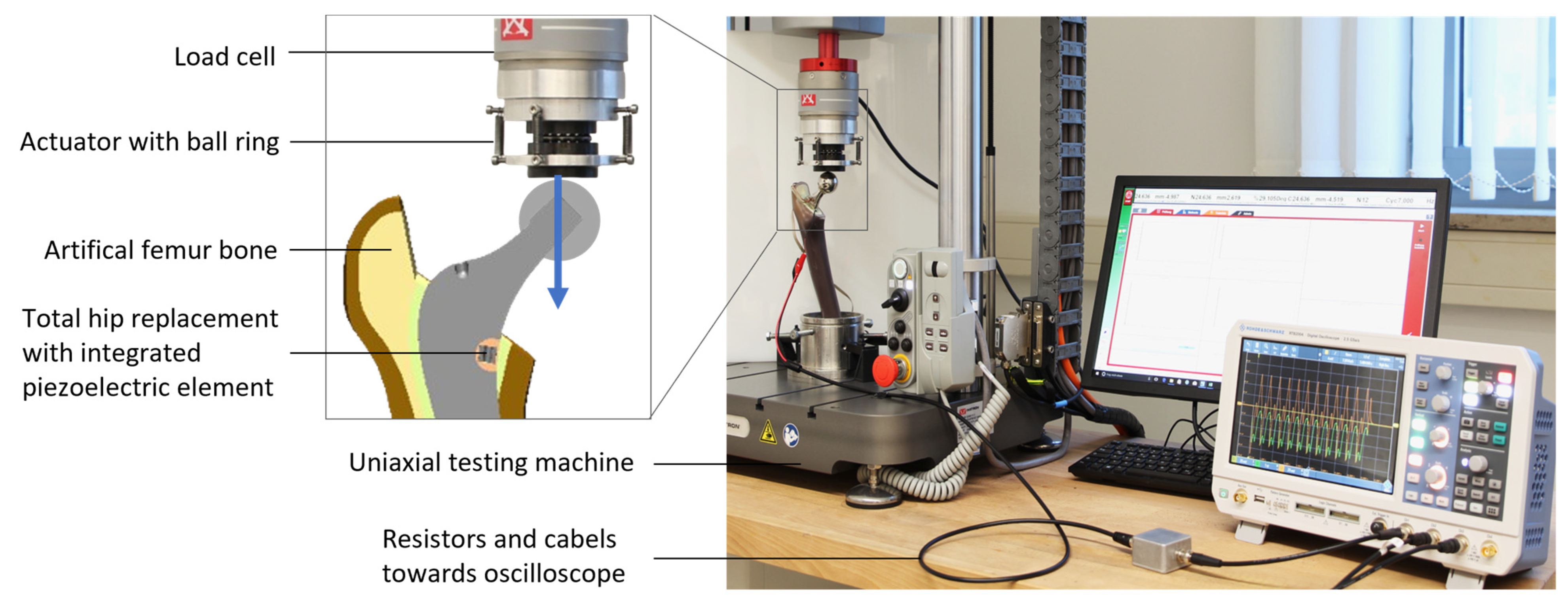
2. Materials and Methods

The experimental test rig from Lange et al. [33] was used for the measurements. The THR stem (Exeter V40, size 37.5 mm N°3, Stryker, Howmedica Osteonics Corp., Mahwah, NJ, USA) with an integrated piezoelectric element (PICMA® actuator, stacked configuration of two elements, outer diameter 5 mm, inner diameter 2.5 mm, height 5 mm, capacity 220 nF) from PI Ceramic GmbH (Lederhose, Germany) was cemented into an artificial femur bone (4th generation, large left, composite bone, solid foam core, Sawbones Europe AB, Malmö, Sweden) and fixed in a specimen holder with embedding resin (Figure 1). The femur is aligned such that the resultant hip joint force during walking points approximately axially downward.
The voltage outputs of hip joint reaction forces of 6–9 subjects from nine different activities (walking, jogging, cycling, stance, stand up, sit down, stairs up, stairs down, knee bend) were examined [21]. The hip joint contact forces used came from Bergmann et al. [21], available on the OrthoLoad database. Due to the limited amount of data, data augmentation was performed by scaling the data to a body weight of 75 kg, 70 kg, and 65 kg and varying the cycle duration by ±10% from the original duration so that a total of 657 different force profiles were applied to the total hip stem.
The force profiles were transformed from the coordinate system used by Bergmann et al. [21] to the coordinate system of the test rig. In the latter, the z-axis is aligned parallel to the force application of the uniaxial testing machine. Since the forces could only be applied uniaxially, the forces deviated from the resultant hip joint contact forces. However, the mean deviation of the maximum applied force from the maxima of the resultant forces of the different activities is minimally smaller, averaging −1.95% (±1.54%). The root mean square error (RMSE) of the total mean force profile averages 36 N (±16 N). The mean and standard deviations of the maximum force of the force profiles finally applied to the THR for each activity can be seen in Table 1.
The transformed hip joint reaction forces from 12 cycles of each activity were applied in the z-direction (blue arrow in Figure 1) to the previously described test rig of the energy-autonomous THR using an electrodynamic uniaxial testing machine (ElectroPuls E3000, Instron, Norwood, MA, USA, with a 5 kN load cell). The voltage outputs produced were simultaneously recorded across a resistor of 500 kOhm using an oscilloscope (R&S®RTB2004, Rohde & Schwarz GmbH & Co. KG., Munich, Germany) with a sampling rate between 1800 Hz (stance) and 10.3 kHz (jogging). More detailed information on the circuit diagram is described in Lange et al. [33].

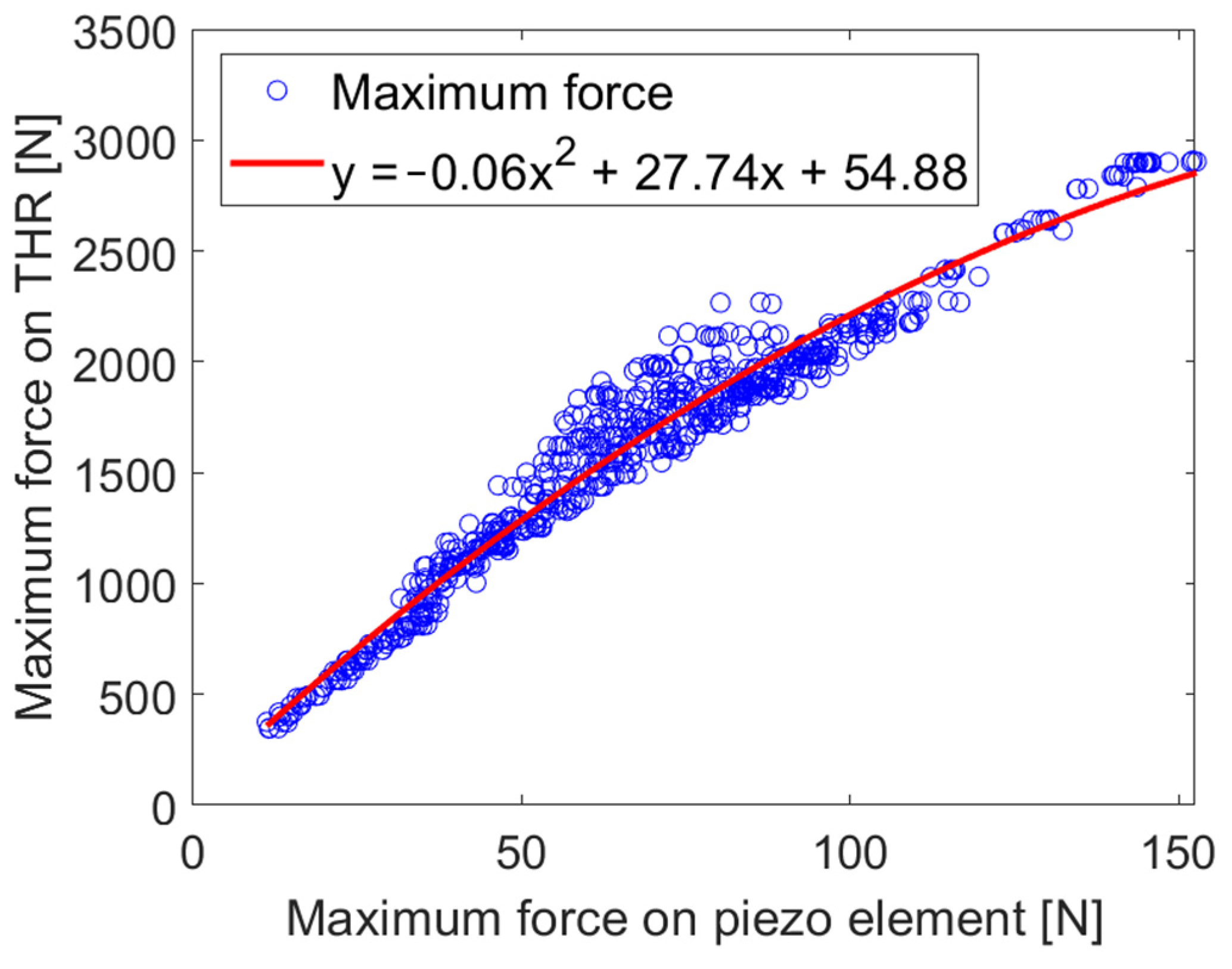
2.1. Calculation of the Maximum Hip Joint Reaction Force

Using MATLAB R2018a (MathWorks Inc., Natick, MA, USA), the voltage outputs were filtered with a 10-point moving average filter to reduce noise and down-sampled at 1000 Hz to bring all outputs to one sampling rate. Then, the total generated voltage of the piezoelectric element was calculated using the resistance between the piezoelectric element and the oscilloscope ( R v a r = 500 kOhm), the internal resistance of the oscilloscope ( R O s c = 1 MOhm), and the fixed resistance ( R p a r = 10,101 Ohm) [33]:
V P i e z t = V O s c t 1 + R v a r R O s c + R p a r R O s c   R p a r
The following equation is used to determine the uniaxial force acting on the piezo element based on the output voltage [35]:
C P e f f d V P i e z t d t + V P i e z t R s u m = d 33 e f f d F t d t
where F t in [N] is the applied force over time t in [s], R s u m is the resistance in [Ω], C P e f f in [nF] is the effective capacitance of the piezoelectric element, and d 33 e f f in [m/V] is the effective voltage constant. C P e f f and d 33 e f f are given by
C P e f f = N 33   T A h
d 33 e f f = N d 33
with the number of piezo layers N , the dielectric permittivity 33   T , the cross-sectional area of the piezo element A in [m2], and the height of the layer thickness h in [m].
The transfer function in the Laplace domain is used to calculate the force acting on the piezo element:
V s F s = d 33 s C p s + 1 R
where s is the Laplace complex frequency. R results in this case, as described by Lange et al. [33]:
R = R O s c R p a r R O s c + R p a r   + R v a r
The exact values of the corresponding piezo element can be seen in Table 2.
One cycle of each measurement was chosen, as little difference exists between the cycles within a measurement. Regressions were calculated with the hip joint reaction force maxima as dependent variables and the calculated force maxima on the piezoelectric element as independent variables. Here, regressions in dependence and a regression independent of the activities were calculated. The maximum forces on the THR were then determined using the regression equations and compared with the forces actually applied.

2.2. Detection of Physical Activity

To detect activity using voltage outputs, a multiclass classification with a leave-one-subject-out cross-validation was carried out. For this purpose, the voltage outputs of one cycle of each measurement were first brought to the same length by padding the time series with zeros in an oriented manner after the longest record, i.e., every data consisted of 13,000 time-domain samples. The data of the respective subject scaled to a weight of 75 kg was used as the test data set for this purpose. The augmented data of the other subjects was used for the training data set. This corresponded to 584 training data points and nine test data points for each subject. Since recordings of all activities were only available for six of the nine subjects, multiclass classification was only conducted for six subjects. A multiclass classification was performed using a random forest with a maximum depth of four. A total of 13,000 features were utilized at each split, and the number of trees was 100. The classification results of each subject were then added together into one confusion matrix. The percentage influence of the most important features contributing to the classification decision was averaged over the subjects studied.
The random forest is a classifier based on an ensemble of decision trees trained using a different randomly selected subset of the training data set. The results of the individual decision trees are merged to make a final prediction. In the case of physical activity detection using voltages, the average of the results of all the individual decision trees is used. Combining many weak decision trees makes the random forest a robust classifier [37]. An advantage of the random forest is that it can usually handle higher-dimensional data, as they exist in the real world, robustly by itself. Therefore, no data reduction through dimensionality reduction (e.g., by a principal component analysis) is required [38].

3. Results

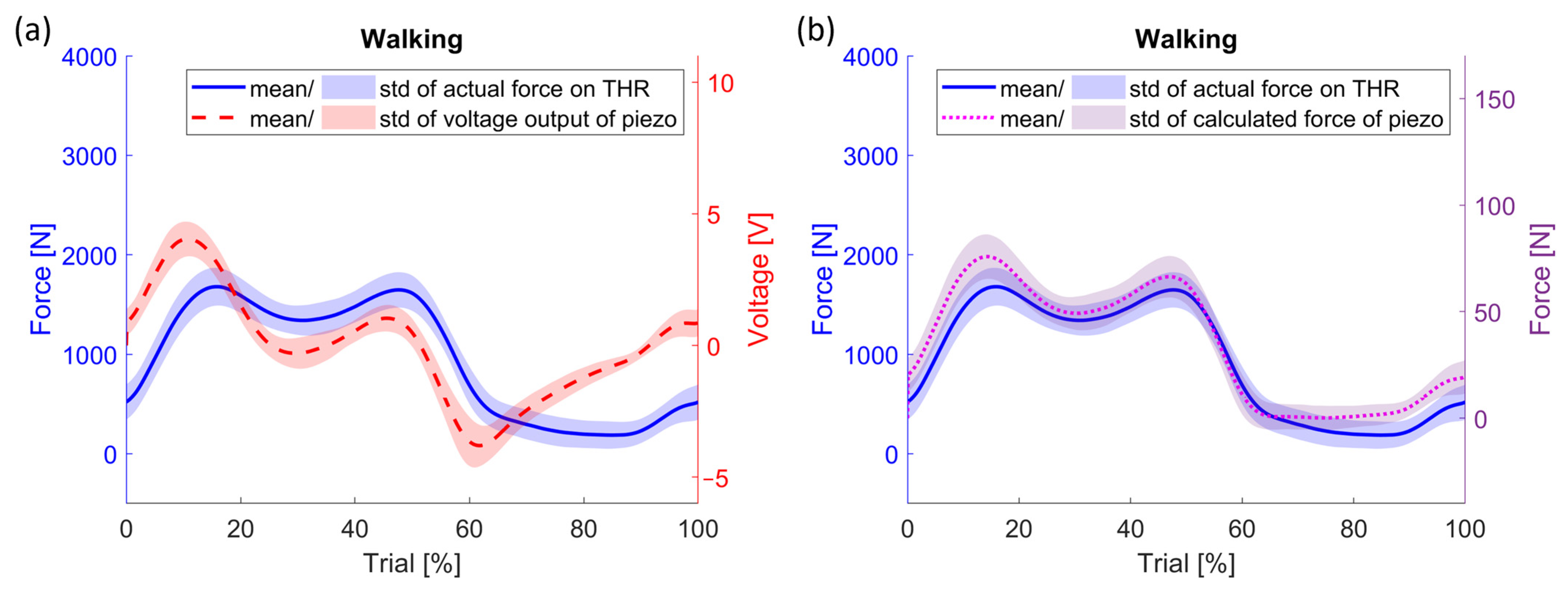
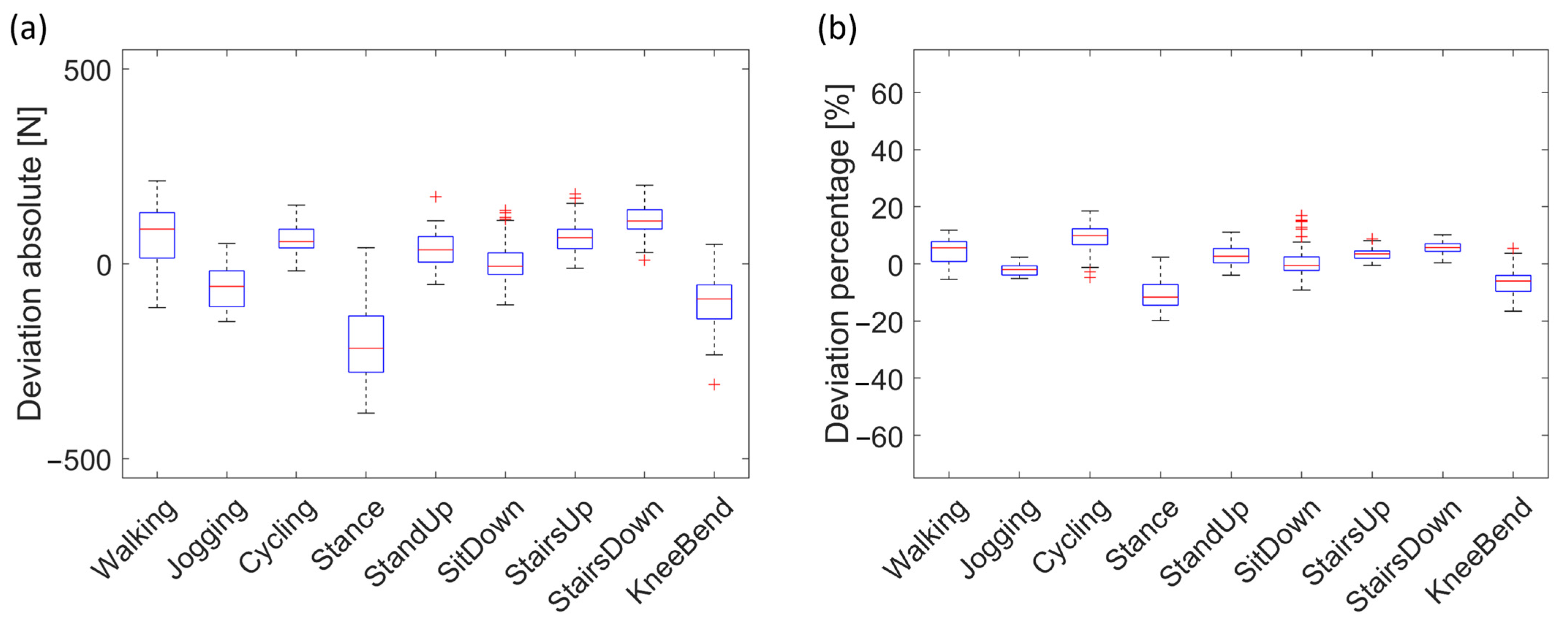
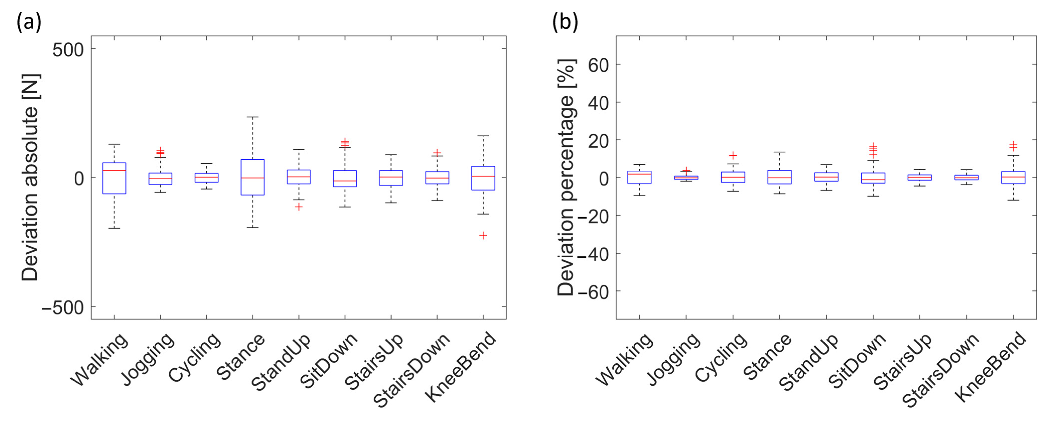
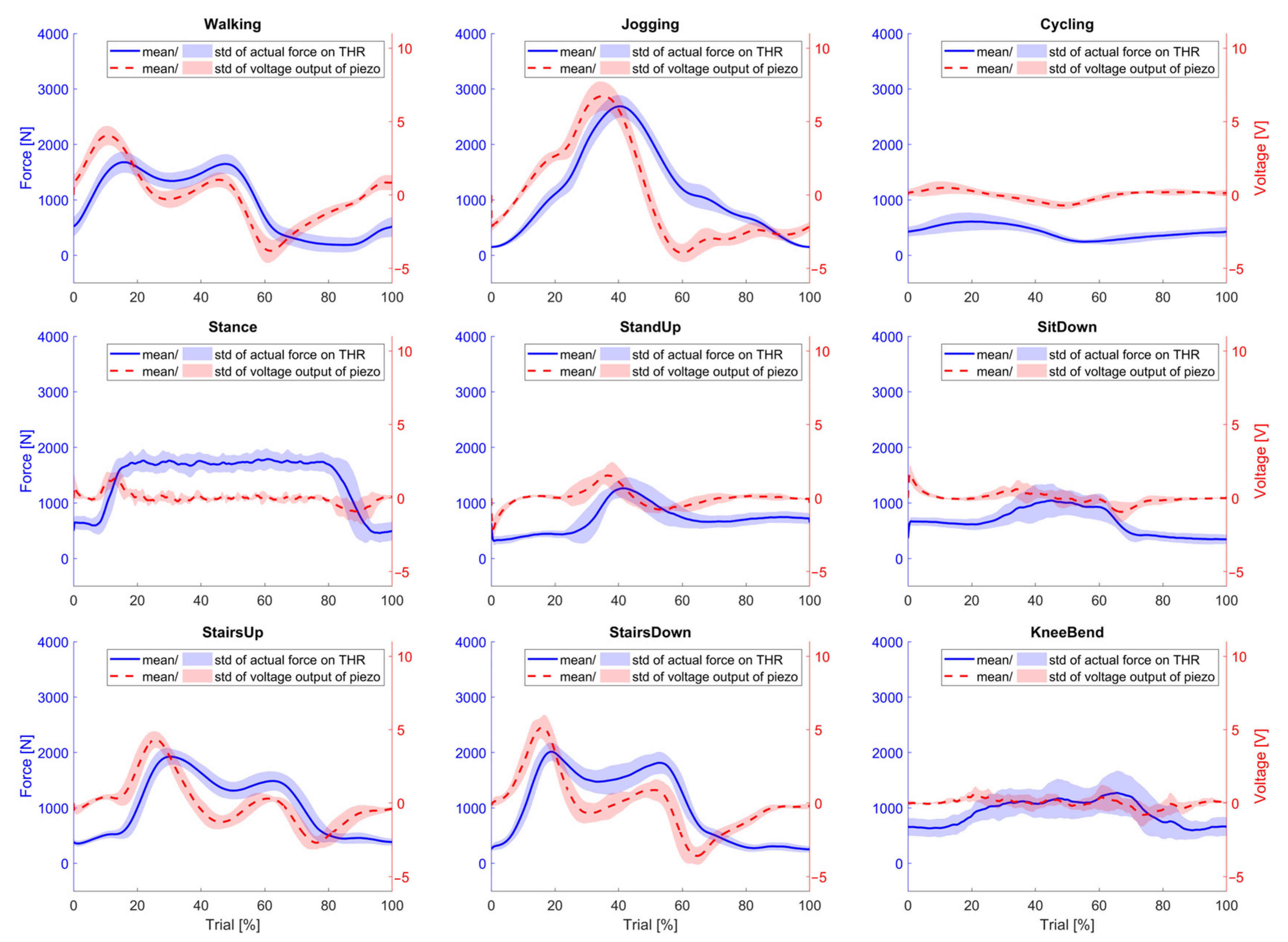
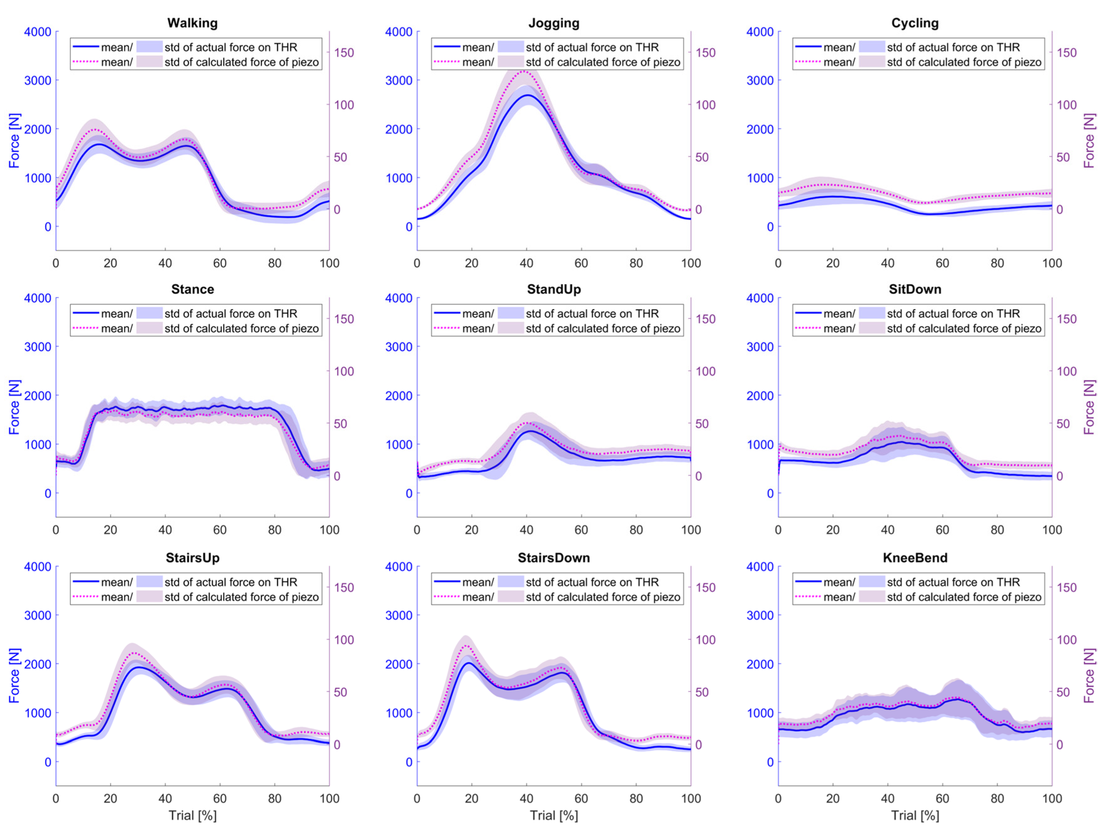
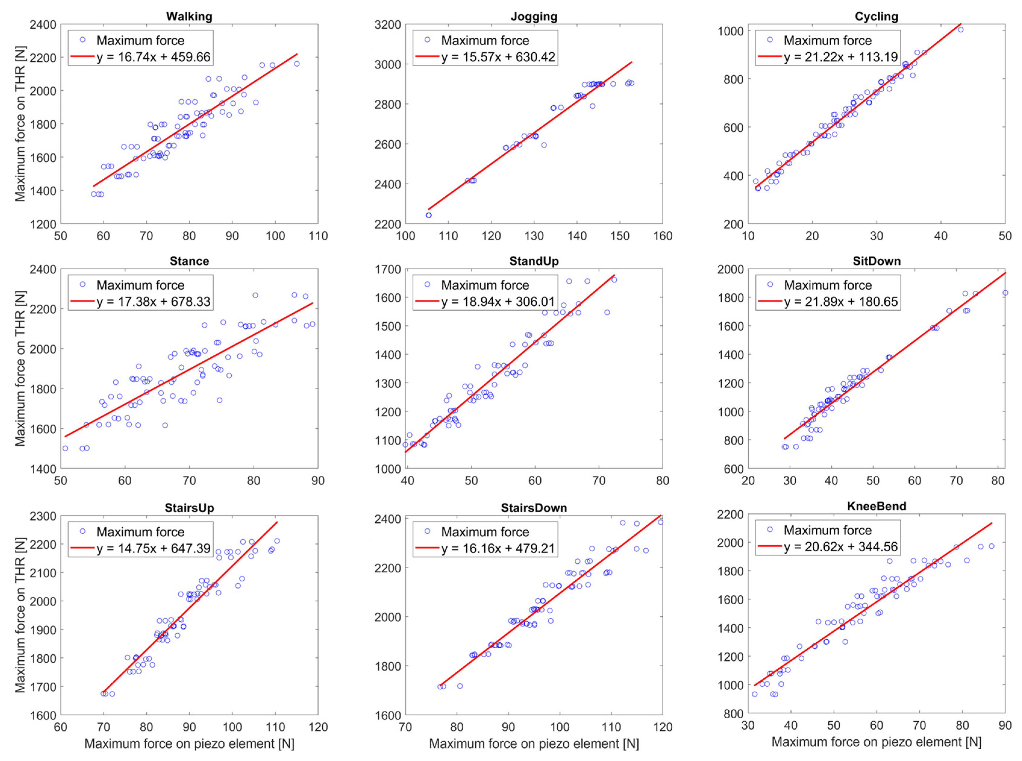
3.1. Maximum Hip Joint Reaction Forces

Figure 2 shows in blue the mean and standard deviation of the augmented force data applied to the energy-autonomous THR scaled to one cycle using the example of walking. On the left side, the generated voltage outputs are plotted, and on the right side, the forces calculated from the voltage outputs acting on the piezoelectric element are shown. The results of all activities can be found in Figure A1 and Figure A2 in Appendix A.
The curves of the calculated forces are very similar to those of the forces applied to the THR. Only slight deviations exist, and the values of the calculated forces are lower overall than those applied to the implant. The coefficient of determination between the calculated maximum forces of all activities and the maximum forces applied to the THR is R2 = 0.97 (p < 0.01), and between the whole trial is R2 = 0.97 (p < 0.01). The second-degree polynomial regression equation shown in Figure 3 shows that the slope of the forces acting on the THR decreases with increasing forces on the piezo element.
The absolute and percentage deviations of the calculated maxima from the actual maximum values applied using the second-degree polynomial regression equation are shown in Figure 4. The maxima of the activities jogging, stance, sit down, and knee bend were generally estimated to be lower, while those of the remaining activities were estimated to be higher than the actual force. The average percentage deviation is 2.49 ± 13.16%.
Furthermore, linear regressions were computed for each activity with the calculated applied maximum forces on the piezo element as the independent variables and the actual applied maximum forces on the THR as the dependent variables, as seen in Figure A3 in Appendix A. The scatter plots here show a predominantly linear relationship for all activities. The corresponding correlation coefficients provided in Table 3 also confirm a high correlation, with a mean coefficient of determination R2 = 0.95 (±0.04) (p < 0.01). Furthermore, the regression lines with regression equations are given in the corresponding figures (Figure A3, Appendix A). The axis intercepts are between 15 N and 22 N, and the slopes are between 113 N and 678 N.
Figure 5 shows the absolute and percentage deviations between the maximum forces calculated by linear regression and the actual maximum forces applied to the THR. The median here is close to zero for almost all activities, both for the absolute and percentage deviations, and lower for all activities than when all maxima are calculated using second-degree regression. Furthermore, the 25th and 75th percentiles of all activities are below ±4%; for the activities of jogging, stairs up, and stairs down, they are even below ±1.5%. The total mean and standard deviation are 0.87 ± 7.28%.

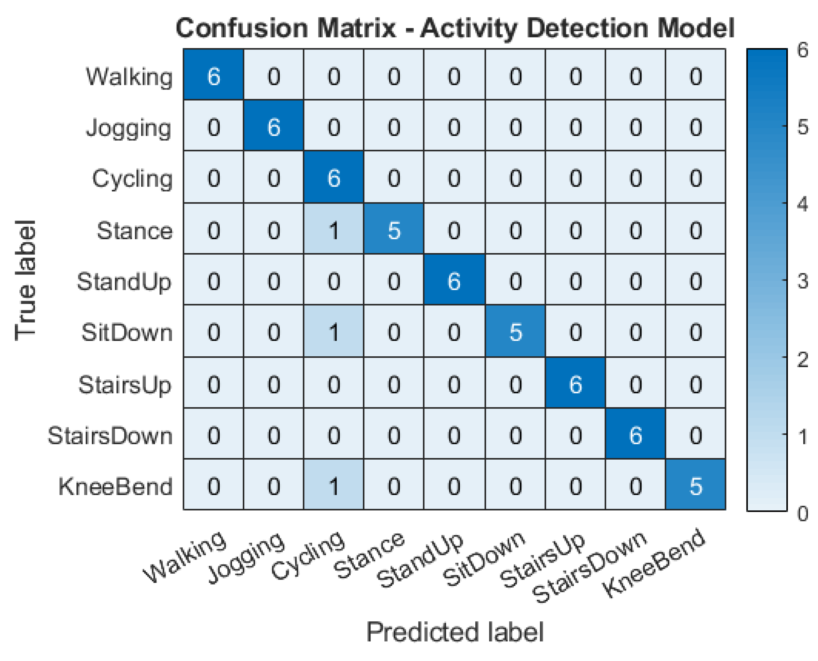
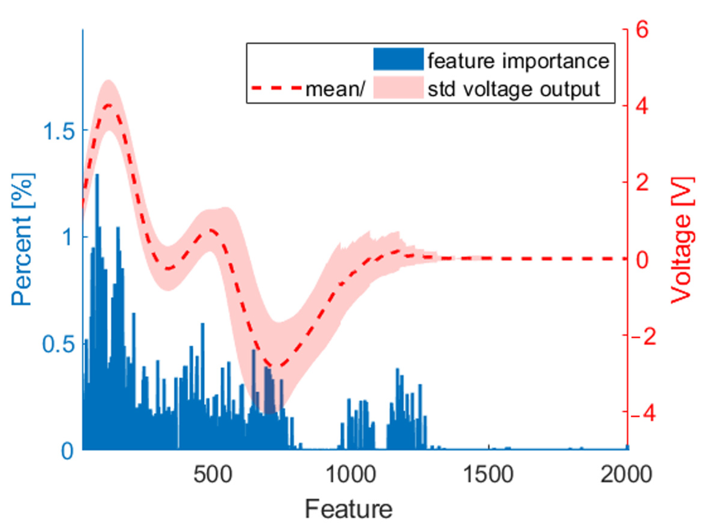
3.2. Physical Activity Recognition

Figure 6 shows the confusion matrix of the activity recognition model, in which the results of all six subjects tested are summarized. The predicted activities are listed in the columns, and the true activities are listed in the rows. The diagonal line shows the activities that were predicted correctly. The results of the confusion matrix show that almost all 45 test data points were correctly assigned to the activities. Only stance, sitting down, and knee bend were incorrectly identified as cycling once. The random forest classification, therefore, has a high overall accuracy of 95%.
The average percentage importance of the features of the investigated subjects for the activity classification decision can be seen in Figure 7. The mean and standard deviation voltage outputs for the activity walking of the whole data set are added as an example. The most important features are mainly located in the first section, i.e., the first part of the voltage outputs has the most influence on which voltage output is assigned to which activity.

4. Discussion

Our study successfully used the generated voltage output of a piezoelectric element integrated into a total hip stem to calculate the maximum resultant forces acting on the THR during different simulated physical activities. Furthermore, the voltage output enabled the detection of these activities.
A simplified test setup was used for the investigation by applying the profiles of hip joint reaction forces of different activities uniaxially to the THR, which is a limitation of this work. Although it could be shown that the deviations between the applied force and the actual resultant forces were minor, this simplified test setup does not reflect the complex musculoskeletal system. This could be solved in the future using a multi-axial joint simulator. The simplified test setup is considered sufficient for an initial test to determine whether the maximum forces acting on the THR can be calculated and activities detected using the electrical voltage outputs. A further limitation is the low experimental data set on the hip joint contact forces used for the investigation. Data augmentation was carried out to address this issue by varying the frequency and magnitude of the forces; however, this involves modified initial data, which limits the variation.
A shift of the maximum between the voltage output and actual applied force is shown for almost every activity, as observed in previous studies as well [33]. This is because not only the magnitude of the force acting on the piezoelectric element plays a role, but also the force rate in the electrical output [29]. Therefore, the formula of Hoummadi et al. [35] considers the voltage over time to calculate the force acting on the piezoelectric element.
The force profiles calculated using the voltage outputs that act axially on the piezo element exhibit a very similar curve to the force profiles applied to the THR. The minor deviations and the overall lower calculated forces can be attributed to the loss of force when transferring the forces from the implant via the UHMW-PE housing to the piezo element. Nevertheless, a very good correlation of R2 = 0.97 (<0.01) exists between the calculated forces on the piezo element and the applied forces. All calculated forces are below 150 N and thus below the blocking force of the piezo element, which is >400 N [39].
The regression between the maximum forces actually applied to the THR and the calculated maximum forces acting on the piezo element, independent of the activity, showed that increasing forces acting on the piezo element are associated with an even smaller increase in the maxima acting on the THR. The non-linear relationship could be attributed to the force transmission to the piezo element as a function of the level and rate of hip joint contact forces. For example, the unirradiated UHMW-PE housing shows a non-linear mechanical response to an applied external load. Only under smaller deformations, at a strain of less than one percent, does the material behave linearly elastic, followed by linear viscoelastic, distributed yielding, viscoplastic flow, and material stiffening with increasing deformity. In addition, higher strain rates increase the material’s stiffness [40,41,42]. According to the second-degree regression, this could lead to the force transmission to the piezo element being higher at high forces. The exact influence of the mechanical behavior of the housing on the force transmission to the piezoelectric element could be predicted using a detailed material model [41,42]. Another reason for the non-linear relationship could be uncertainties in calculating the force on the piezo element. In the conversion formula, the piezoelectric charge constant d 33 and the permittivity number 33   were considered to be constant. However, these coefficients only describe the material properties under low loads. With higher force application and higher force rate, the two coefficients show non-linear behavior [43]. Other studies also reported a non-linear behavior of the d 33 constant when applying similar forces [32,35,44]. A non-linear model such as that from Cheng et al. [45] could calculate a more accurate force applied to the piezoelectric element. Furthermore, stiffer materials could be used for housing and piezo elements to improve force transmission or minimize non-linear behavior [43].
The maximum forces acting on the THR calculated using a second-degree polynomial regression equation show deviations of 2.49 ± 13.16% of the actual maximum forces. This relatively high deviation may be due to the previously described factors influencing the level and rate of the applied hip joint forces on the transmission and the calculation of the forces on the piezo element.
The influencing factors described above can be minimized by regressions depending on the activities, as the heights and rates of hip joint contact forces are comparable within an activity. The relationship between the calculated forces on the piezo element and the forces actually applied to the THR could thus be described linearly. The activities with higher force effects and higher force rates—jogging, walking, stairs up, and stairs down—show lower slopes of the regression lines than the remaining movements—cycling, standing up, sitting down, knee bending, and stance. This reinforces the assumption about the influence of force level and rate in calculating the maximum force.
A calculation of the maximum forces using the linear, activity-dependent regression shows a clear minimization of the deviation from the actual maximum forces for all activities. The average deviation was 0.87 ± 7.28%. The remaining deviations between the forces calculated using linear activity-dependent regression and the actual forces on the THR can be attributed to the deviating heights and rates of the force effects within the activity and to measurement uncertainties in the measurement chain. The results of the deviations are comparable with those of similar studies. Hoummadi et al. [35] showed a maximum error between the calculated and actual applied force of 3.6% when applying a sinusoidal force of 50 N to 1500 N at 1 Hz to a simplified replication tibial bearing of a total knee replacement (TKR) with six integrated piezo elements. Safaei et al. found a maximum error of less than 2.5% for a simplified tibial bearing of a TKR with four piezo elements [32], an error of less than 6% for six piezo elements, and an error of less than 4.5% for a design with eight piezo elements [44]. The maximum forces were determined by adding all piezo elements’ calculated forces.
The piezo element in the energy-autonomous THR is aligned so that the maxima of the resultant forces act approximately axially on the piezo element surface to achieve the maximum possible voltage output and prevent shear forces for the safety of the piezo element [33]. In reality, the resultant force will not always point in the direction of the cylinder axis of the piezo element. In order to record all three force components, multi-axis piezo elements could be integrated in the future.
It should also be noted that the general possibility of calculating the maximum forces acting on the THR using the voltage outputs was successfully demonstrated in this work. The regression equations would have to be individually adapted later. For example, the mechanical material properties of the bone, THR, and housing influence the force transmission. The geometry and offset of the implant used are also relevant. A larger offset leads to a lower contact force parallel to the cylinder axis of the piezo element with the same applied force [33,34].
Another aim of this work was to use the converted voltage outputs for physical activity recognition. The random forest is a prominent machine learning method for detecting activities [46,47,48,49]. This work also showed that a random forest classifier can correctly predict the activities with a very high accuracy of 95%. However, it should be noted that the amount of data used was small. Although data augmentation was carried out, this data is based on the initial data. In the future, the model could be further trained by obtaining additional voltage outputs through measurements in vivo.
The activity recognition model was tested with cycles that had already been synchronized and truncated. In a further step, the voltage outputs of an entire daily routine could be used as a test data set. The analysis of the important features has shown that the first temporal section of the voltage output of one cycle is particularly important for recognizing the activity. This information could be used for data reduction later.
In order to be able to identify physical activities in everyday life even with more complex data, information from other sensors could be used, such as accelerometers integrated into smart hip implants, to capture even more characteristic gait features. Combining information from different modalities shows promising results in the recognition of the physical activity and movements of humans [47,50,51].
In future studies, an implantable platform will be used to transmit the voltage output wirelessly via Bluetooth to an extracorporeal device for further data processing, according to [52,53]. The self-generated energy of the piezo element is to be provided to support the energy supply of this implantable platform.

5. Conclusions

Our study shows that the piezo element integrated into a THR stem, which was primarily integrated for a self-sufficient energy supply, can be used to determine the mechanical loading on the implant and for activity detection. This represents a new possibility of permanently monitoring the hip joint reaction forces in everyday life in patients with THR. In this way, information can be obtained about which forces occur in situ during specific physical activity, e.g., providing data for health activities and therapeutic purposes.

Author Contributions

Conceptualization, F.G. and D.K.; methodology, F.G., S.S. and D.K.; software, F.G. and S.S.; data curation, F.G. and H.B.; investigation, F.G.; resources, R.B. and D.K.; writing—original draft preparation, F.G.; writing—review and editing, H.B., S.S., R.B. and D.K.; visualization, F.G.; supervision, R.B. and D.K.; project administration, R.B. and D.K.; funding acquisition, R.B. and D.K. All authors have read and agreed to the published version of the manuscript.

Funding

This work was supported by the Deutsche Forschungsgemeinschaft (DFG, German Research Foundation)—SFB 1270/2 [grant number: 299150580].

Institutional Review Board Statement

Not applicable.

Informed Consent Statement

Not applicable.

Data Availability Statement

The data presented in this study are available on request from the corresponding author.

Acknowledgments

We gratefully acknowledge the funding of the German Research Foundation (Deutsche For-schungsgemeinschaft, DFG) within the Collaborative Research Centre 1270/2 ELAINE.

Conflicts of Interest

The authors declare no conflicts of interest.

Appendix A

Figure A1. Mean profiles and standard deviations of the applied forces on the THR (blue) and the corresponding voltage outputs (red).
Technologies 12 00051 g0a1
Figure A2. Mean profiles and standard deviations of the applied forces on the THR (blue) and the calculated forces on the piezoelectric element (purple).
Technologies 12 00051 g0a2
Figure A3. Linear regressions between the maximum forces actually applied to the THR and the calculated maximum forces on the piezoelectric element.
Technologies 12 00051 g0a3

References

  1. Knight, S.R.; Aujla, R.; Biswas, S.P. Total Hip Arthroplasty—Over 100 years of operative history. Orthop. Rev. 2011, 3, e16. [Google Scholar] [CrossRef]
  2. The Swedish Arthroplasty Register. Annual Report 2022; The Swedish Arthroplasty Register: Gothenburg, Sweden, 2022. [Google Scholar]
  3. OECD Publishing. Health at a Glance 2021; OECD Publishing: Paris, France, 2021; ISBN 978-92-64-89762-5. [Google Scholar]
  4. Pabinger, C.; Lothaller, H.; Portner, N.; Geissler, A. Projections of hip arthroplasty in OECD countries up to 2050. Hip Int. 2018, 28, 498–506. [Google Scholar] [CrossRef]
  5. Ledet, E.H.; Liddle, B.; Kradinova, K.; Harper, S. Smart implants in orthopedic surgery, improving patient outcomes: A review. Innov. Entrep. Health 2018, 5, 41–51. [Google Scholar] [CrossRef] [PubMed]
  6. Soares Dos Santos, M.P.; Bernardo, R.M.C. Bioelectronic multifunctional bone implants: Recent trends. Bioelectron. Med. 2022, 8, 15. [Google Scholar] [CrossRef] [PubMed]
  7. Iyengar, K.P.; Kariya, A.D.; Botchu, R.; Jain, V.K.; Vaishya, R. Significant capabilities of SMART sensor technology and their applications for Industry 4.0 in trauma and orthopaedics. Sens. Int. 2022, 3, 100163. [Google Scholar] [CrossRef]
  8. Kelmers, E.; Szuba, A.; King, S.W.; Palan, J.; Freear, S.; Pandit, H.G.; van Duren, B.H. Smart Knee Implants: An Overview of Current Technologies and Future Possibilities. Indian J. Orthop. 2023, 57, 635–642. [Google Scholar] [CrossRef]
  9. Peres, I.; Rolo, P.; Soares Dos Santos, M.P. Multifunctional Smart Bone Implants: Fiction or Future?-A New Perspective. Front. Bioeng. Biotechnol. 2022, 10, 912081. [Google Scholar] [CrossRef] [PubMed]
  10. Qiblawey, Y.; Chowdhury, M.E.H.; Musharavati, F.; Zalnezhad, E.; Khandakar, A.; Islam, M.T. Instrumented Hip Implant: A Review. IEEE Sens. J. 2021, 21, 7179–7194. [Google Scholar] [CrossRef]
  11. Cachão, J.H.; Soares Dos Santos, M.P.; Bernardo, R.; Ramos, A.; Bader, R.; Ferreira, J.A.F.; Torres Marques, A.; Simões, J.A.O. Altering the Course of Technologies to Monitor Loosening States of Endoprosthetic Implants. Sensors 2019, 20, 104. [Google Scholar] [CrossRef]
  12. Schmidt, C.; Zimmermann, U.; van Rienen, U. Modeling of an optimized electrostimulative hip revision system under consideration of uncertainty in the conductivity of bone tissue. IEEE J. Biomed. Health Inform. 2015, 19, 1321–1330. [Google Scholar] [CrossRef]
  13. Bansod, Y.D.; Kebbach, M.; Kluess, D.; Bader, R.; van Rienen, U. Finite element analysis of bone remodelling with piezoelectric effects using an open-source framework. Biomech. Model. Mechanobiol. 2021, 20, 1147–1166. [Google Scholar] [CrossRef] [PubMed]
  14. Raben, H.; Kämmerer, P.W.; Bader, R.; van Rienen, U. Establishment of a Numerical Model to Design an Electro-Stimulating System for a Porcine Mandibular Critical Size Defect. Appl. Sci. 2019, 9, 2160. [Google Scholar] [CrossRef]
  15. Khare, D.; Basu, B.; Dubey, A.K. Electrical stimulation and piezoelectric biomaterials for bone tissue engineering applications. Biomaterials 2020, 258, 120280. [Google Scholar] [CrossRef]
  16. van Drongelen, S.; Holder, J.; Stief, F. Lower limb joint loading in patients with unilateral hip osteoarthritis during bipedal stance and the effect of total hip replacement. Front. Bioeng. Biotechnol. 2023, 11, 1190712. [Google Scholar] [CrossRef]
  17. Alves, S.A.; Polzehl, J.; Brisson, N.M.; Bender, A.; Agres, A.N.; Damm, P.; Duda, G.N. Ground reaction forces and external hip joint moments predict in vivo hip contact forces during gait. J. Biomech. 2022, 135, 111037. [Google Scholar] [CrossRef]
  18. Damm, P.; Brackertz, S.; Streitparth, F.; Perka, C.; Bergmann, G.; Duda, G.N.; Winkler, T. ESB Clinical Biomechanics Award 2018: Muscle atrophy-related increased joint loading after total hip arthroplasty and their postoperative change from 3 to 50 months. Clin. Biomech. 2019, 65, 105–109. [Google Scholar] [CrossRef] [PubMed]
  19. Haffer, H.; Popovic, S.; Martin, F.; Hardt, S.; Winkler, T.; Damm, P. In vivo loading on the hip joint in patients with total hip replacement performing gymnastics and aerobics exercises. Sci. Rep. 2021, 11, 13395. [Google Scholar] [CrossRef] [PubMed]
  20. Damm, P.; Graichen, F.; Rohlmann, A.; Bender, A.; Bergmann, G. Total hip joint prosthesis for in vivo measurement of forces and moments. Med. Eng. Phys. 2010, 32, 95–100. [Google Scholar] [CrossRef]
  21. Bergmann, G.; Bender, A.; Dymke, J.; Duda, G.; Damm, P. Standardized Loads Acting in Hip Implants. PLoS ONE 2016, 11, e0155612. [Google Scholar] [CrossRef]
  22. Babaei, N.; Hannani, N.; Dabanloo, N.J.; Bahadori, S. A Systematic Review of the Use of Commercial Wearable Activity Trackers for Monitoring Recovery in Individuals Undergoing Total Hip Replacement Surgery. Cyborg Bionic Syst. 2022, 2022, 9794641. [Google Scholar] [CrossRef]
  23. Bocchetta, G.; Fiori, G.; Sciuto, S.A.; Scorza, A. Performance of Smart Materials-Based Instrumentation for Force Measurements in Biomedical Applications: A Methodological Review. Actuators 2023, 12, 261. [Google Scholar] [CrossRef]
  24. Zaszczyńska, A.; Gradys, A.; Sajkiewicz, P. Progress in the Applications of Smart Piezoelectric Materials for Medical Devices. Polymers 2020, 12, 2754. [Google Scholar] [CrossRef] [PubMed]
  25. 176-1987; IEEE Standard on Piezoelectricity. IEEE/Institute of Electrical and Electronics Engineers Incorporated: Piscataway, NJ, USA, 1988; ISBN 0-7381-2411-7.
  26. Shaikh, F.K.; Zeadally, S. Energy harvesting in wireless sensor networks: A comprehensive review. Renew. Sustain. Energy Rev. 2016, 55, 1041–1054. [Google Scholar] [CrossRef]
  27. Safaei, M.; Sodano, H.A.; Anton, S.R. A review of energy harvesting using piezoelectric materials: State-of-the-art a decade later (2008–2018). Smart Mater. Struct. 2019, 28, 113001. [Google Scholar] [CrossRef]
  28. Sezer, N.; Koç, M. A comprehensive review on the state-of-the-art of piezoelectric energy harvesting. Nano Energy 2021, 80, 105567. [Google Scholar] [CrossRef]
  29. Rupitsch, S.J. Piezoelectric Sensors and Actuators; Springer: Berlin/Heidelberg, Germany, 2019; ISBN 978-3-662-57532-1. [Google Scholar]
  30. Almouahed, S.; Gouriou, M.; Hamitouche, C.; Stindel, E.; Roux, C. Design and evaluation of instrumented smart knee implant. IEEE Trans. Biomed. Eng. 2011, 58, 971–982. [Google Scholar] [CrossRef] [PubMed]
  31. Safaei, M.; Meneghini, R.M.; Anton, S.R. Compartmental force and contact location sensing in instrumented total knee replacements. Med. Eng. Phys. 2020, 83, 64–72. [Google Scholar] [CrossRef] [PubMed]
  32. Safaei, M.; Meneghini, R.M.; Anton, S.R. Force detection, center of pressure tracking, and energy harvesting from a piezoelectric knee implant. Smart Mater. Struct. 2018, 27, 114007. [Google Scholar] [CrossRef] [PubMed]
  33. Lange, H.-E.; Arbeiter, N.; Bader, R.; Kluess, D. Performance of a Piezoelectric Energy Harvesting System for an Energy-Autonomous Instrumented Total Hip Replacement: Experimental and Numerical Evaluation. Materials 2021, 14, 5151. [Google Scholar] [CrossRef]
  34. Lange, H.-E.; Hohlfeld, D.; Bader, R.; Kluess, D. A piezoelectric energy harvesting concept for an energy-autonomous instrumented total hip replacement. Smart Mater. Struct. 2020, 29, 115051. [Google Scholar] [CrossRef]
  35. Hoummadi, E.; Safaei, M.; Anton, S.R. Design, analysis, and fabrication of a piezoelectric force plate. In Health Monitoring of Structural and Biological Systems 2017; Kundu, T., Ed.; SPIE Smart Structures and Materials + Nondestructive Evaluation and Health Monitoring; SPIE: Portland, OR, USA, 2017; p. 101700W. [Google Scholar]
  36. PI Ceramic GmbH. Material Coefficients PIC255: v4.3; PI Ceramic GmbH: Lederhose, Germany, 2017. [Google Scholar]
  37. Luwe, Y.J.; Lee, C.P.; Lim, K.M. Wearable sensor-based human activity recognition with ensemble learning: A comparison study. IJECE 2023, 13, 4029. [Google Scholar] [CrossRef]
  38. Belgiu, M.; Drăguţ, L. Random forest in remote sensing: A review of applications and future directions. ISPRS J. Photogramm. Remote Sens. 2016, 114, 24–31. [Google Scholar] [CrossRef]
  39. PI Ceramic GmbH. Data Sheet Round PICMA® Chip Actuators: Miniature Multilayer Piezo Actuators with and without Inner Hole; PI Ceramic GmbH: Lederhose, Germany, 2019. [Google Scholar]
  40. Bowden, A.E.; Oneida, E.; Bergström, J. Computer Modeling and Simulation of UHMWPE. In UHMWPE Biomaterials Handbook; Elsevier: Amsterdam, The Netherlands, 2009; pp. 519–532. ISBN 9780123747211. [Google Scholar]
  41. Bergström, J.S.; Kurtz, S.M.; Rimnac, C.M.; Edidin, A.A. Constitutive modeling of ultra-high molecular weight polyethylene under large-deformation and cyclic loading conditions. Biomaterials 2002, 23, 2329–2343. [Google Scholar] [CrossRef] [PubMed]
  42. Bergström, J.S.; Rimnac, C.M.; Kurtz, S.M. Prediction of multiaxial mechanical behavior for conventional and highly crosslinked UHMWPE using a hybrid constitutive model. Biomaterials 2003, 24, 1365–1380. [Google Scholar] [CrossRef] [PubMed]
  43. Picht, G.; Bouvier, V.; Frank, S.; Koruza, J.; Felten, F.; Lindemann, G. Ferroelastic Properties of PZT: Characterization Under Compressive and Tensile Stress, Finite-Element Simulation, and Lifetime Calculation. IEEE Trans. Ultrason. Ferroelectr. Freq. Control 2018, 65, 1542–1551. [Google Scholar] [CrossRef] [PubMed]
  44. Safaei, M.; Dupre, S.; Hoummadi, E.; Anton, S.R. Design, Analysis, and Fabrication of a Piezoelectric Force Tray for Total Knee Replacements. J. Intell. Mater. Syst. Struct. 2019, 30, 3163–3175. [Google Scholar] [CrossRef] [PubMed]
  45. Cheng, L.; Liu, W.; Hou, Z.-G.; Yu, J.; Tan, M. Neural-Network-Based Nonlinear Model Predictive Control for Piezoelectric Actuators. IEEE Trans. Ind. Electron. 2015, 62, 7717–7727. [Google Scholar] [CrossRef]
  46. Taylor, W.; Shah, S.A.; Dashtipour, K.; Zahid, A.; Abbasi, Q.H.; Imran, M.A. An Intelligent Non-Invasive Real-Time Human Activity Recognition System for Next-Generation Healthcare. Sensors 2020, 20, 2653. [Google Scholar] [CrossRef] [PubMed]
  47. Qiu, S.; Zhao, H.; Jiang, N.; Wang, Z.; Liu, L.; An, Y.; Zhao, H.; Miao, X.; Liu, R.; Fortino, G. Multi-sensor information fusion based on machine learning for real applications in human activity recognition: State-of-the-art and research challenges. Inf. Fusion 2022, 80, 241–265. [Google Scholar] [CrossRef]
  48. Attal, F.; Mohammed, S.; Dedabrishvili, M.; Chamroukhi, F.; Oukhellou, L.; Amirat, Y. Physical Human Activity Recognition Using Wearable Sensors. Sensors 2015, 15, 31314–31338. [Google Scholar] [CrossRef]
  49. Narayanan, A.; Desai, F.; Stewart, T.; Duncan, S.; Mackay, L. Application of Raw Accelerometer Data and Machine-Learning Techniques to Characterize Human Movement Behavior: A Systematic Scoping Review. J. Phys. Act. Health 2020, 17, 360–383. [Google Scholar] [CrossRef] [PubMed]
  50. Yadav, S.K.; Tiwari, K.; Pandey, H.M.; Akbar, S.A. A review of multimodal human activity recognition with special emphasis on classification, applications, challenges and future directions. Knowl.-Based Syst. 2021, 223, 106970. [Google Scholar] [CrossRef]
  51. Nweke, H.F.; Teh, Y.W.; Mujtaba, G.; Al-Garadi, M.A. Data fusion and multiple classifier systems for human activity detection and health monitoring: Review and open research directions. Inf. Fusion 2019, 46, 147–170. [Google Scholar] [CrossRef]
  52. Yoo, S.; Lee, J.; Joo, H.; Sunwoo, S.-H.; Kim, S.; Kim, D.-H. Wireless Power Transfer and Telemetry for Implantable Bioelectronics. Adv. Healthc. Mater. 2021, 10, e2100614. [Google Scholar] [CrossRef]
  53. Plocksties, F.; Kober, M.; Niemann, C.; Heller, J.; Fauser, M.; Nüssel, M.; Uster, F.; Franz, D.; Zwar, M.; Lüttig, A.; et al. The software defined implantable modular platform (STELLA) for preclinical deep brain stimulation research in rodents. J. Neural Eng. 2021, 18, 056032. [Google Scholar] [CrossRef]
Figure 1. Experimental measurement setup: a uniaxial testing machine to apply the force profiles to the total hip stem, and an oscilloscope to record the output voltage.
Technologies 12 00051 g001
Figure 2. Mean value and standard deviation of the applied force and the voltage output (a) and the calculated force acting on the piezo element (b) for the example of walking.
Technologies 12 00051 g002
Figure 3. Second-degree regression between the maximum forces actually applied to the THR and the calculated maximum forces acting on the piezoelectric element, independent of activities.
Technologies 12 00051 g003
Figure 4. Box plots for (a) absolute and (b) percentage deviation of the maximum applied forces calculated using the second-degree regression equation and the actual maximum applied forces on the THR.
Technologies 12 00051 g004
Figure 5. Box plots for (a) absolute and (b) percentage deviation of the maximum applied forces calculated using the linear regression equations and the actual maximum applied forces on the THR.
Technologies 12 00051 g005
Figure 6. Confusion matrix with the true activities and the activities predicted with the physical activity detection model, summarized for the six subjects studied.
Technologies 12 00051 g006
Figure 7. Average feature importance of the activity classification model of the investigated subjects in [%]. As an example, the voltage outputs during walking are added.
Technologies 12 00051 g007
Table 1. Mean value and standard deviation of the maxima of the applied force on the total hip stem of each activity based on [21].
ActivityWalkingJoggingCyclingStanceStand
Up
Sit
Down
Stairs
Up
Stairs
Down
Knee
Bend
Maximum force on THR [N]1757
(±185)
2708
(±200)
634,48
(±159)
1882
(±182)
1314
(±160)
1151
(±259)
1960
(±145)
2049
(±160)
1503
(±288)
Table 2. Parameters and values of the piezoelectric element used [36].
Parameter [Unit]Value
h [m]0.005
N [-] 86
A [m2]1.473 × 10⁻⁵
d 33 [m/Vm]3.996 × 10−10
0   [ A s / V m ] 8.854 × 10⁻¹²
33   T / 0 [-]1751
Table 3. Coefficient of determination between the calculated maximum force on the piezo and the applied maximum force on the THR.
ActivityWalkingJoggingCyclingStanceStand
Up
Sit
Down
Stairs
Up
Stairs
Down
Knee
Bend
Coefficient of determination R20.910.980.990.870.970.980.960.970.96
Disclaimer/Publisher’s Note: The statements, opinions and data contained in all publications are solely those of the individual author(s) and contributor(s) and not of MDPI and/or the editor(s). MDPI and/or the editor(s) disclaim responsibility for any injury to people or property resulting from any ideas, methods, instructions or products referred to in the content.

