A Modified Criss-Cross-Based T-Type MLI with Reduced Power Components
Abstract
:1. Introduction
- (I).
- Renewable energy systems: MLIs are widely used in renewable energy systems such as solar photovoltaic (PV) inverters and wind turbine generators for grid integration. They help convert the DC power generated by renewable sources into grid-compatible AC power with improved efficiency and power quality [7,8].
- (II).
- Motor drives: MLIs are employed in adjustable speed motor drives for controlling the speed and torque of electric motors used in industrial and commercial applications. They provide smoother operation and higher efficiency compared to traditional two-level inverters [9]
- (III).
- Grid-tied inverters: MLIs are utilized in grid-tied inverters for feeding power from distributed energy resources (DERs) such as solar panels or batteries into the electrical grid. They enable precise control of power flow and support functions like reactive power compensation and voltage regulation [10,11].
- (IV).
- High-voltage direct current (HVDC) transmission: MLIs are used in HVDC transmission systems for converting AC power to DC power at the sending end and vice versa at the receiving end. They help improve the efficiency and stability of long-distance power transmission [12].
- (V).
2. Proposed Circuit Topology
- (I).
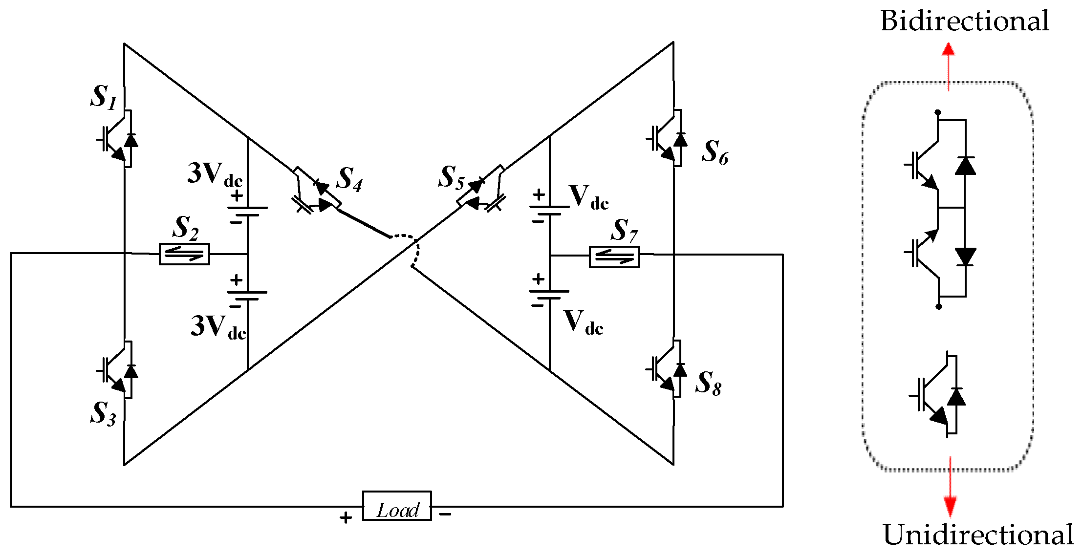
- Common emitter configuration: This configuration utilizes an insulated gate bipolar transistor in a common emitter configuration. The common emitter setup involves the emitter terminal being common between the input and output circuits. In this arrangement, the IGBT serves as the main switching element, controlling the flow of current bidirectionally, as depicted in Figure 2a.
- (II).
- Power switch with four-diode configuration: This configuration incorporates a diode bridge switch. A diode bridge consists of four diodes arranged in a bridge configuration, allowing for current to flow bidirectionally. However, this setup typically involves more diodes compared to other configurations, potentially leading to higher conduction losses, as depicted in Figure 2b.
- (III).
- Common collector configuration: This configuration employs an IGBT in a common collector setup. In a common collector arrangement, the collector terminal serves as the common connection point between the input and output circuits. Here, the IGBT controls the current flow bidirectionally while providing a different configuration compared to the common emitter setup as depicted in Figure 2c.

Modulation and Control of MLI
3. Modes of Operation
- Switches S1, S5, and S8 are activated to produce +8Vdc, as illustrated in Figure 4a, while S3, S4, and S6 are turned ON to generate −8Vdc.
- The power switches S1, S5, and S7 are turned ON to generate +7Vdc, as illustrated in Figure 3b, whereas S3, S4, and S7 are activated to generate −7Vdc.
- Switches S1, S5, and S6 are activated to achieve +6Vdc, as illustrated in Figure 4c, whereas S3, S4, and S8 are turned ON to generate −6Vdc.
- Switches S2, S5, and S8 are turned ON to achieve +5Vdc, as illustrated in Figure 4d, whereas S2, S4, and S6 are turned ON to generate −5Vdc.
- Switches S2, S5, and S7 are turned ON to achieve +4Vdc, as illustrated in Figure 4e, whereas S2, S4, and S7 are turned ON to generate −4Vdc.
- Switches S2, S5, and S6 are turned ON to achieve +3Vdc, as illustrated in Figure 4f, whereas S2, S4, and S8 are activated to generate −3Vdc.
- Switches S3, S8, and S5 are turned ON to achieve +2Vdc, as illustrated in Figure 4g, whereas S1, S4, and S6 are activated to generate −2Vdc.
- Switches S2, S5, and S7 are activated to generate +Vdc, as illustrated in Figure 4h, whereas S1, S4, and S7 are activated to produce −Vdc.
- Switches S3, S5, and S6 are activated to produce 0Vdc.
4. Comparative Study
5. Simulation and Experimental Result
6. Conclusions
Author Contributions
Funding
Informed Consent Statement
Data Availability Statement
Conflicts of Interest
References
- Bana, P.R.; Panda, K.P.; Naayagi, R.T.; Siano, P.; Panda, G. Recently developed reduced switch multilevel inverter for renewable energy integration and drives application: Topologies, comprehensive analysis and comparative evaluation. IEEE Access 2019, 7, 54888–54909. [Google Scholar] [CrossRef]
- Gupta, K.K.; Ranjan, A.; Bhatnagar, P.; Sahu, L.K.; Jain, S. Multilevel Inverter Topologies with Reduced Device Count: A Review. IEEE Trans. Power Electron. 2016, 31, 135–151. [Google Scholar] [CrossRef]
- Veenstra, M.; Rufer, A. Control of a hybrid asymmetric multilevel inverter for competitive medium-voltage industrial drives. IEEE Trans. Ind. Appl. 2005, 41, 655–664. [Google Scholar] [CrossRef]
- Chakraborty, A. Advancements in power electronics and drives in interface with growing renewable energy resources. Renew. Sustain. Energy Rev. 2011, 15, 1816–1827. [Google Scholar] [CrossRef]
- Mahato, B.; Jana, K.C.; Thakura, P.R. Constant V/f control and frequency control of isolated winding induction motor using nine-level three-phase inverter. Iran. J. Sci. Technol. Trans. Electr. Eng. 2019, 43, 123–135. [Google Scholar] [CrossRef]
- Shahin, A.; Hinaje, M.; Martin, J.-P.; Pierfederici, S.; Rael, S.; Davat, B. High voltage ratio DC-DC converter for fuel-cell applications. IEEE Trans. Ind. Electron. 2010, 57, 3944–3955. [Google Scholar] [CrossRef]
- Agrawal, R.; Jain, S. Multilevel inverter for interfacing renewable energy sources with low/medium- and high-voltage grids. IET Renew. Power Gener. 2017, 11, 1822–1831. [Google Scholar] [CrossRef]
- Yadav, D.; Singh, N.; Bhadoria, V.; Vita, V.; Fotis, G.; Tsampasis, E.G.; Maris, T.I. Analysis of the Factors Influencing the Performance of Single- and Multi-Diode PV Solar Modules. IEEE Access 2023, 11, 95507–95525. [Google Scholar] [CrossRef]
- Somasekhar, V.T.; Gopakumar, K.; Baiju, M.R.; Mohapatra, K.K.; Umanand, L. A multilevel inverter system for an induction motor with open-end windings. IEEE Trans. Ind. Electron. 2005, 52, 824–836. [Google Scholar] [CrossRef]
- Mahto, K.K.; Pal, P.K.; Das, P.; Mittal, S.; Mahato, B. A New Design of Multilevel Inverter Based on T-Type Symmetrical and Asymmetrical DC Sources. Iran. J. Sci. Technol. Trans. Electr. Eng. 2023, 47, 639–657. [Google Scholar] [CrossRef]
- Maris, T.I.; Kourtesi, S.; Ekonomou, L.; Fotis, G. Modeling of a single phase photovoltaic inverter. Sol. Energy Mater. Sol. Cells 2007, 91, 1713–1725. [Google Scholar] [CrossRef]
- Kala, P.; Arora, S. A comprehensive study of classical and hybrid multilevel inverter topologies for renewable energy applications. Renew. Sustain. Energy Rev. 2017, 76, 905–931. [Google Scholar] [CrossRef]
- Gritter, D.; Kalsi, S.S.; Henderson, N. Variable speed electric drive options for electric ships. In Proceedings of the IEEE Electric Ship Technologies Symposium, Philadelphia, PA, USA, 27 July 2005; pp. 347–354. [Google Scholar] [CrossRef]
- Bernet, S. Recent developments of high power converters for industry and traction applications. IEEE Trans. Power Electron. 2000, 15, 1102–1117. [Google Scholar] [CrossRef]
- Alishah, R.S.; Nazarpour, D.; Hosseini, S.H.; Sabahi, M. Novel topologies for symmetric, asymmetric, and cascade switched-diode multilevel converter with minimum number of power electronic components. IEEE Trans. Ind. Electron. 2014, 61, 5300–5310. [Google Scholar] [CrossRef]
- Dickerson, J.A.; Ottaway, G.H. Transformerless Power Supply with Line to Load Isolation. U.S. Patent 3,596,369, 3 August 1971. [Google Scholar]
- Meynard, T.A.; Foch, H. Multi-level conversion: High voltage choppers and voltage-source inverters. In Proceedings of the PESC Record—IEEE Annual Power Electronics Specialists Conference, Toledo, Spain, 29 June–3 July 1992; pp. 397–403. [Google Scholar] [CrossRef]
- Baker, R.H. Bridge Converter Circuit. U.S. Patent 4,270,163, 26 May 1981. [Google Scholar]
- Nabae, A.; Takahashi, I.; Agaki, H. A New Neutral-Point-Clamped PWM Inverter. IEEE Trans. Ind. Appl. 1981, 17, 518–523. [Google Scholar] [CrossRef] [PubMed]
- Mcmurray, W. Fast Response Stepped-Wave Switching Power Converter Circuit. U.S. Patent 3,581,212, 25 May 1971. [Google Scholar]
- Baker, I.R.H.; Bannister, L.H. Electric Power Converter. U.S. Patent 3,867,643, 18 February 1975. [Google Scholar]
- Vijeh, M.; Rezanejad, M.; Samadaei, E.; Bertilsson, K. A general review of multilevel inverters based on main submodules: Structural point of view. IEEE Trans. Power Electron. 2019, 34, 9479–9502. [Google Scholar] [CrossRef]
- Prabaharan, N.; Palanisamy, K. A comprehensive review on reduced switch multilevel inverter topologies, modulation techniques and applications. Renew. Sustain. Energy Rev. 2017, 76, 1248–1282. [Google Scholar] [CrossRef]
- Majumdar, S.; Mahato, B.; Jana, K.C. Analysis of most optimal multi-unit multi-level inverter having minimum components and lower standing voltage. IETE Tech. Rev. 2021, 38, 520–536. [Google Scholar] [CrossRef]
- Mahto, K.K.; Mahato, B.; Chandan, B.; Das, D.; Das, P.; Fotis, G.; Mann, M. A New Symmetrical Source-Based DC/AC Converter with Experimental Verification. Electronics 2024, 13, 1975. [Google Scholar] [CrossRef]
- Zhou, K.; Wang, D. Relationship Between Space-Vector Modulation and Three-Phase Carrier-Based PWM: A Comprehensive Analysis. IEEE Trans. Ind. Electron. 2002, 49, 186–196. [Google Scholar] [CrossRef]
- Perez, M.; Rodriguez, J.; Pontt, J.; Kouro, S. Power Distribution in Hybrid Multicell Converter with Nearest Level Modulation. In Proceedings of the 2007 IEEE International Symposium on Industrial Electronics, Vigo, Spain, 4–7 June 2007; pp. 736–741. [Google Scholar] [CrossRef]
- Leon, J.I.; Kouro, S.; Franquelo, L.G.; Rodriguez, J.; Wu, B. The Essential Role and the Continuous Evolution of Modulation Techniques for Voltage-Source Inverters in the Past, Present, and Future Power Electronics. IEEE Trans. Ind. Electron. 2016, 63, 2688–2701. [Google Scholar] [CrossRef]
- Panda, K.P.; Panda, G. Application of swarm optimization-based modified algorithm for selective harmonic elimination in reduced switch count multilevel inverter. IET Power Electron. 2018, 11, 1472–1482. [Google Scholar] [CrossRef]
- Kangarlu, M.F.; Babaei, E. Cross-switched multilevel inverter: An innovative topology. IET Power Electron. 2013, 6, 642–651. [Google Scholar] [CrossRef]
- Ajami, A.; Oskuee, M.R.; Khosroshahi, M.T.; Mokhberdoran, A. Cascade-multi-cell multilevel converter with reduced number of switches. IET Power Electron. 2014, 7, 2914–2924. [Google Scholar] [CrossRef]
- Gautam, S.P.; Kumar, L.; Gupta, S. Hybrid topology of symmetrical multilevel inverter using less number of devices. IET Power Electron. 2015, 8, 2125–2135. [Google Scholar] [CrossRef]
- Gupta, K.K.; Jain, S. Topology for multilevel inverters to attain maximum number of levels from given DC sources. IET Power Electron. 2012, 5, 435–446. [Google Scholar] [CrossRef]
- Babaei, E.; Hosseini, S.H. New cascaded multilevel inverter topology with minimum number of switches. Energy Convers. Manag. 2009, 50, 2761–2767. [Google Scholar] [CrossRef]
- Alishah, R.S.; Nazarpour, D.; Hosseini, S.H.; Sabahi, M. Reduction of Power Electronic Elements in Multilevel Converters Using a New Cascade Structure. IEEE Trans. Ind. Electron. 2015, 62, 256–269. [Google Scholar] [CrossRef]
- Ajami, A.; Oskuee, M.R.J.; Mokhberdoran, A.; Van den Bossche, A. Developed cascaded multilevel inverter topology to minimise the number of circuit devices and voltage stresses of switches. IET Power Electron. 2013, 7, 459–466. [Google Scholar] [CrossRef]



| S1 | S2 | S3 | S4 | S5 | S6 | S7 | S8 | |
|---|---|---|---|---|---|---|---|---|
| +8Vdc | √ | × | × | √ | × | × | × | √ |
| +7Vdc | √ | × | × | × | √ | × | √ | × |
| +6Vdc | √ | × | × | × | √ | √ | × | × |
| +5Vdc | × | √ | × | × | √ | × | × | √ |
| +4Vdc | × | √ | × | × | √ | × | √ | × |
| +3Vdc | × | √ | × | × | √ | √ | × | × |
| +2Vdc | × | × | √ | × | √ | × | × | √ |
| +1Vdc | × | √ | × | × | √ | × | √ | × |
| 0Vdc | × | × | √ | × | √ | √ | × | × |
| −1Vdc | √ | × | × | √ | × | × | √ | × |
| −2Vdc | √ | × | × | √ | × | √ | × | × |
| −3Vdc | × | √ | × | √ | × | × | × | √ |
| −4Vdc | × | √ | × | √ | × | × | √ | × |
| −5Vdc | × | √ | × | √ | × | √ | × | × |
| −6Vdc | × | × | √ | √ | × | × | × | √ |
| −7Vdc | × | × | √ | √ | × | × | × | × |
| −8Vdc | × | × | √ | √ | × | √ | × | × |
| Cited Papers | Total Number of Switches | Isolated DC Sources | Capacitors | Main Diodes |
|---|---|---|---|---|
| [30] | 0 | |||
| [31] | 3 | 0 | ||
| [32] | 2 | |||
| [33] | 1 | 2 | ||
| [34] | 1 | |||
| [35] | 1 | 4 | ||
| [36] | 0 | |||
| Proposed MLI | 0 |
| Cited Papers | Voltage Level | Total Number of Switches | Isolated DC Sources | Capacitors | Main Diodes |
|---|---|---|---|---|---|
| [30] | 17 | 18 | 8 | 0 | 18 |
| [31] | 17 | 24 | 8 | 0 | 24 |
| [32] | 17 | 14 | 2 | 6 | 2 |
| [33] | 17 | 36 | 1 | 8 | 32 |
| [34] | 17 | 20 | 1 | 8 | 20 |
| [35] | 17 | 11 | 1 | 8 | 4 |
| [36] | 17 | 20 | 8 | 0 | 20 |
| Proposed MLI | 17 | 8 | 4 | 0 | 10 |
| Parameters | Specification | |
|---|---|---|
| Switching parameters IGBT | CT-60AM-18F: 900 V, 60 A Von, IGBT = 1.3 V, Von, Dio= 1.5 V, RDio = 0.01 Ω, RIGBT = 0.11Ω, β = 3 | |
| Types of switching devices and their controlling elements | Driver Controller | TLP250: 10–35 V, ±1.5 A DS1103 |
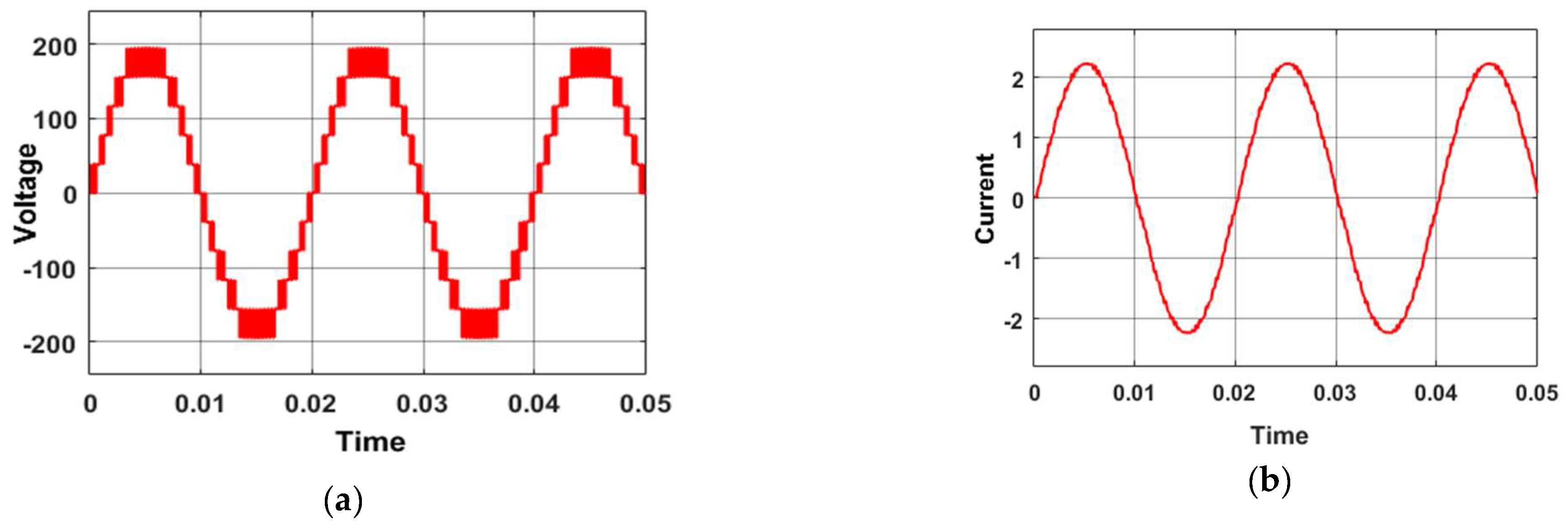
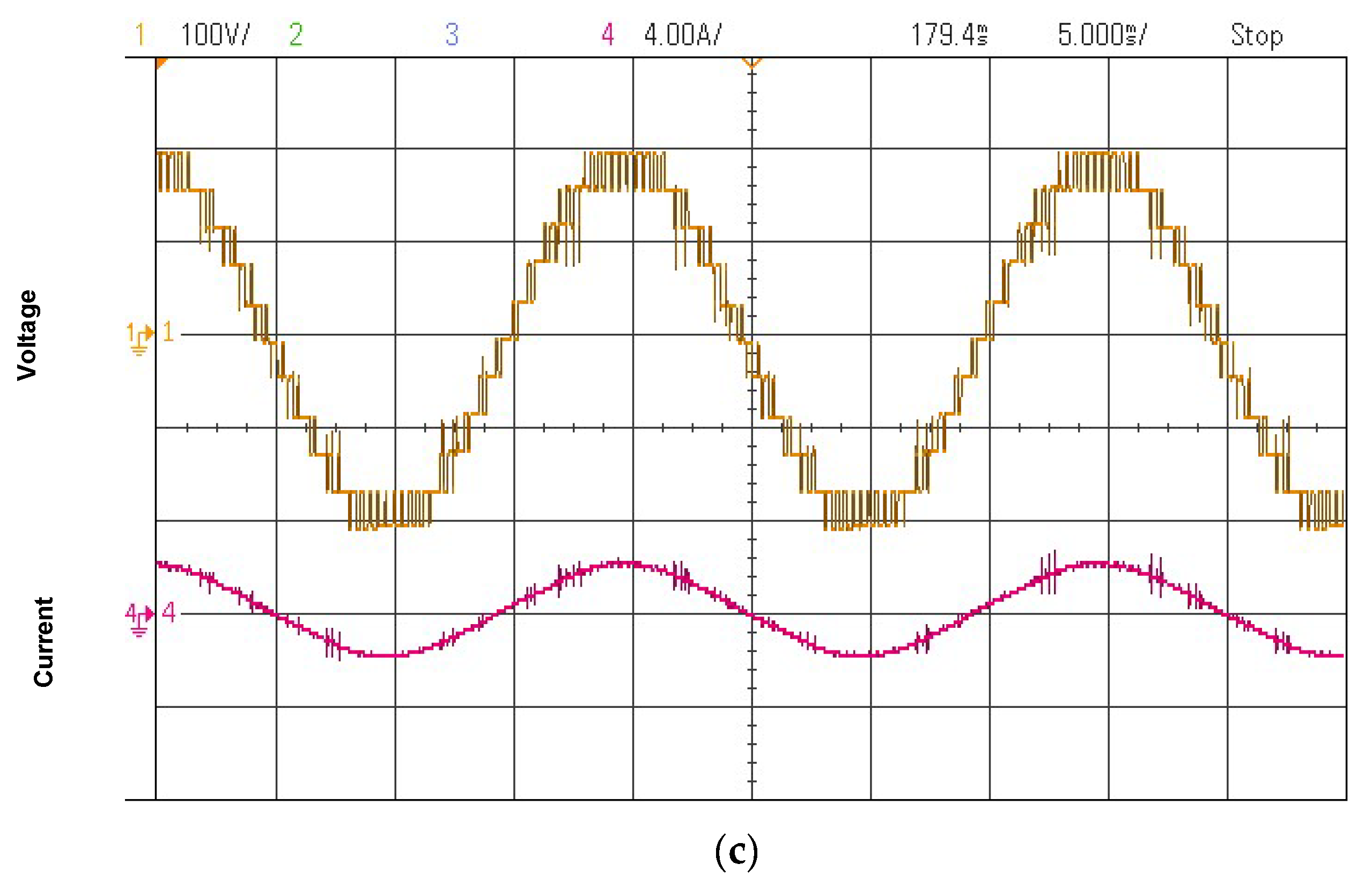
| Parameters of simulation and experiment | (V1 = V2 = 39 V, V3 = V4 = 117 V) R = 180 Ω, L = 150 mH, Vpk = 196 V, Ipk = 0.78 A, MI = 0.6 | |
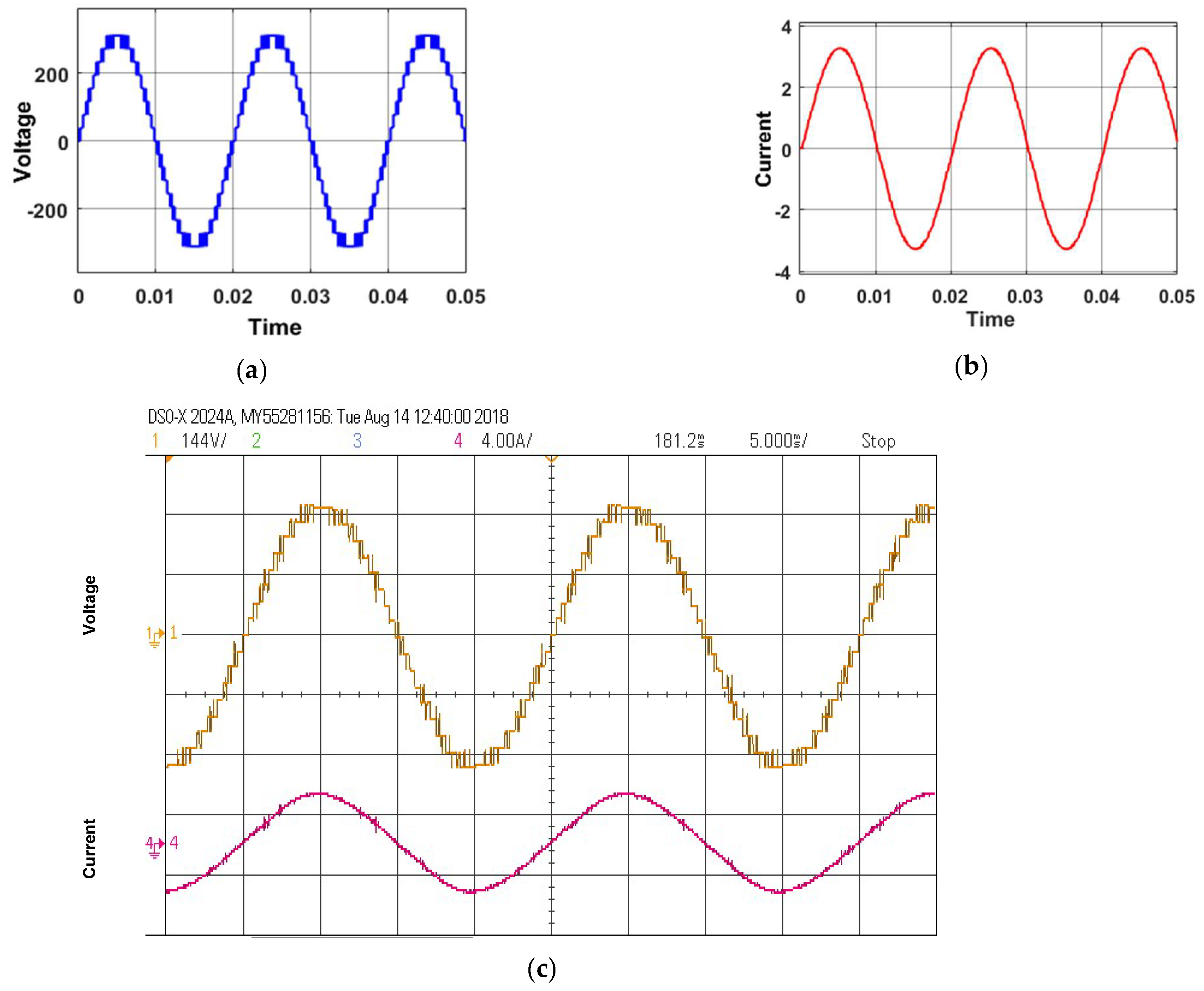
| (V1 = V2 = 39 V, V3 = V4 = 117 V) R = 180 Ω, L = 150 mH, Vpk = 320 V, Ipk= 1.17 A, MI = 1 | ||
| (V1 = V2 = 39 V, V3 = V4 = 117 V) R = 90 Ω, L = 25 mH, Vpk = 196 V, Ipk = 2.2 A, MI = 0.6 | ||
| (V1 = V2 = 39 V, V3 = V4 = 117 V) R = 90 Ω, L = 25 mH, Vpk = 320 V, Ipk = 3.2 A, MI = 1 | ||
Disclaimer/Publisher’s Note: The statements, opinions and data contained in all publications are solely those of the individual author(s) and contributor(s) and not of MDPI and/or the editor(s). MDPI and/or the editor(s) disclaim responsibility for any injury to people or property resulting from any ideas, methods, instructions or products referred to in the content. |
© 2024 by the authors. Licensee MDPI, Basel, Switzerland. This article is an open access article distributed under the terms and conditions of the Creative Commons Attribution (CC BY) license (https://creativecommons.org/licenses/by/4.0/).
Share and Cite
Mahto, K.K.; Mahato, B.; Chandan, B.; Das, D.; Das, P.; Kumari, S.; Vita, V.; Pavlatos, C.; Fotis, G. A Modified Criss-Cross-Based T-Type MLI with Reduced Power Components. Technologies 2024, 12, 90. https://doi.org/10.3390/technologies12060090
Mahto KK, Mahato B, Chandan B, Das D, Das P, Kumari S, Vita V, Pavlatos C, Fotis G. A Modified Criss-Cross-Based T-Type MLI with Reduced Power Components. Technologies. 2024; 12(6):90. https://doi.org/10.3390/technologies12060090
Chicago/Turabian StyleMahto, Kailash Kumar, Bidyut Mahato, Bikramaditya Chandan, Durbanjali Das, Priyanath Das, Swati Kumari, Vasiliki Vita, Christos Pavlatos, and Georgios Fotis. 2024. "A Modified Criss-Cross-Based T-Type MLI with Reduced Power Components" Technologies 12, no. 6: 90. https://doi.org/10.3390/technologies12060090
APA StyleMahto, K. K., Mahato, B., Chandan, B., Das, D., Das, P., Kumari, S., Vita, V., Pavlatos, C., & Fotis, G. (2024). A Modified Criss-Cross-Based T-Type MLI with Reduced Power Components. Technologies, 12(6), 90. https://doi.org/10.3390/technologies12060090


