Abstract
The timely reintegration into their daily routine of patients suffering from work-related musculoskeletal disorders is a priority in medical rehabilitation. This can be accomplished by means of certain procedures and adequate medical rehabilitation equipment. Starting from these considerations this paper proposes an original constructive solution of a rehabilitation device designed for the passive mobilization of the neck joint in the sagittal and frontal plane. The constructive solution that is put forward uses a pneumatic muscle as the actuation element, ensuring the adaptability of the equipment to the particular pain tolerance of each patient. The construction and dimensioning calculations of the equipment are presented, followed by the determination of the torsional rigidity and compliance permitted by the system. Based on the results the paper concludes with recommendations for the optimum deployment of the rehabilitation equipment.
1. Introduction
The cervical spine forms the complex neck joint and consists of the first seven vertebrae. It supports the weight of the head and enables it to carry out a wide range of movements in the three anatomical planes. Part of the complex neck joint, the atlantooccipital and atlantoaxial joints enable flexion-extension, rotation (to the left and right, respectively) and tilting (to the left and the right, respectively) of the head. Besides the vertebrae the neck joint also includes muscles, nerves, tendons and ligaments, each contributing specifically to its mobility and stabilization.
Due to its extremely complex structure the neck joint is frequently affected consequently to problems of the cervical spine and of the surrounding soft tissue and nerves. Such affections include cervical radiculopathy, cervical degenerative disk disease, cervical spondylosis, cervical spinal fracture, cervical spinal cord compression, neck pain, etc. [1]. Some of the significant causes for these disorders of the musculoskeletal system that affect the neck joint are due to the tasks performed at the workplace and to challenging conditions of the work environment. Such work-related musculoskeletal disorders or WMSDs [2,3] are caused by faulty, nonergonomic postures at work, by repetitive motions, excessive use of body force, vibrations, mechanical compression and temperature.
To date WMSDs have been and remain the most frequent work-related health problem in the European Union. As WMSDs affect all employees from all fields of activity, the consecutive costs to companies and society are high. A study conducted by the European Agency for Safety and Health at Work reveals that about 42% of workers reporting different musculoskeletal disorders suffer from problems of the neck joint and of the shoulders [4]. The Labour Force Survey conducted in Great Britain on a sample of 470,000 individuals states that the majority of workplace-related complaints concern the neck (45%), back (39%) and lower limbs (16%) [5].
As follows from these studies, it is the neck joint that is most frequently affected by WMSDs, and requires effective rehabilitation solutions. The recovery of this joint needs to cover the motor state (muscle tone), the sensorial state (proprioception) and last but not least the psycho-social and professional status of the patient. The treatment of WMSDs involves several approaches, as appropriate: restricting mobility, applying heat or cold, and stretching that facilitate circulation, ease muscle tension and reduce the need for medication and surgery [6].
Neck affections lend themselves to high success rate rehabilitation, thus enhancing patient chances of swift reintegration into everyday activity. Modern therapeutical methods have shortened recovery periods and reduced the failure rate of the treatments used in such pathologies. A key role in rapid recovery is the utilization of adequate rehabilitation equipment conceived for the neck joint. By causing repetitive controlled movements of the neck joint such equipment have a positive impact on improving muscle force and recovering lost or diminished functions. Continuous Passive Motion–CPM is one of the efficient methods that ensure the rehabilitation of the neck joint that is mobilized by external devices with mechanical, electromechanical or pneumatic actuation. The purpose of such mobilization is to avoid the building up of a fibrous tissue and implicitly to reduce joint stiffness. Some of the essential characteristics CPM-based rehabilitation equipment of the neck joint benefits from are the control of the applied forces, of the movement amplitudes, speeds, accelerations, as well as of the duration and frequency of the exercises. The possibility of modifying all these parameters between certain limits allows adjusting the rehabilitation exercises to the clinical state and the pain threshold of the patients [7].
Variable stiffness, also known as adjustable compliance is another feature required from such rehabilitation equipment. The deployment of actuation systems of this type offers the possibility of minimizing the large forces occurring in collisions (shocks), of safe interaction with the user and of storing and releasing energy into passive elastic elements. A system with adjustable compliance has the capacity of rapidly adapting to the state of the patients and their pain tolerance.
An extensive and detailed survey on the wearable assistive robotic devices used for head and neck rehabilitation is reported by Doss et al. in [8]. The paper presents the latest trends related to rehabilitation equipment, the use of various sensors, actuation devices and control techniques meant to generate an optimum set of movements of the head/neck.
At present there are several variants of neck joint rehabilitation equipment with different operational principles available on the marketplace. One of the variants is the Cervical muscles exerciser G160 provided by David Health Solutions [9]. This equipment mobilizes the neck joint in a transverse plane activating the typically neglected rotating muscles of the head. The electrical actuation of this rehabilitation system allows for testing of mobility and isometric strength in both directions of movement. Variant G140 Cervical Extension/Lateral Flexion Device mobilizes extension and lateral flexion of the cervical spine activating extensor and lateral flexor muscles [10].
Another available equipment is conceived for the recovery of patients suffering from dropped head syndrome (DHS). This manifests by weakness and pain of the neck muscles that are unable to lift or mobilize the head. This dynamic neck rehabilitation system (Car-Neck) is actuated by means of cable transmission and helps DHS patients to carry out flexion/extension motions [11].
Kim et al. propose in [12] a postural correction system designed for forward head posture (FHP) patients. FHP is typical for longtime computer and smartphone users. The equipment consists of flexibility sensors, a rigid chin support and is actuated by an artificial pneumatic muscle. It is a passive rehabilitation system that while enabling the patient to hold their head in a vertical position does not, however, restore the dynamic movements of the head/neck [12].
Yue et al. propose in [13] a parallel manipulator based cervical exoskeleton developed for mimicking head/neck motions. The system can generate flexion/extension of the neck within a ±15° range, and of ±20° for lateral bending, respectively.
BTE Technologies put forward a complex rehabilitation equipment of the neck joint that generates movements in the frontal, sagittal and transverse plane. Called Multi-Cervical Unit (MCU) this equipment is electrically actuated and destined for patients suffering from neck pain, whiplash-associated disorders (WAD), and general cervical spine disorders. All characteristics of the joint movements are matched against reference values and stored in the computer, thus ensuring a good traceability of each patient’s evolution [14].
Another manufacturer of neck joint rehabilitation equipment if DBC of Finland. The Multi-Purpose Low-Friction Unit (MLU), Cervical Extension (CE), and Cervical 3-Dimensional Rotation (C3R) are pieces of equipment that enable bidimensional elliptic movements in the sagittal plane or coupled movements of posterior sliding and rotation by the transverse axis [15].
The neck joint rehabilitation devices presented above can be used by patients either at home or in specialist clinics supervised by a physical therapist. They are actuated manually, mechanically, pneumatically, or in most cases electrically. At present pneumatic actuation is less deployed, although using compressed air ensures the compliant behavior of the device, adaptable to the patient’s complaint. Worth mentioning though is a wrist-inspired magneto-pneumatic hybrid-driven soft actuator with bidirectional torsion capabilities based on the Kresling origami unit, studied in [16]. The proposed solution can be adapted and used also in medical rehabilitation devices of the neck joint.
The overview of neck joint rehabilitation equipment available on the marketplace has not led to identifying a complex neck joint rehabilitation device that is actuated pneumatically and allows movements along several directions. Against the background offered by this finding this paper presents a novel solution of a neck joint rehabilitation system that generates recovery movements in the sagittal and frontal planes.
The paper is structured in six sections. The introductory part is followed by a Section 2 studying the biomechanics of the neck joint in the frontal and sagittal anatomic planes. This study yields the input data required for designing the rehabilitation equipment. The Section 3 presents the selected constructive solution and the working principle of the rehabilitation equipment. The operational stages of the equipment and the generation of movements in the two planes are presented. The Section 4 of the paper concerns the dimensioning of the rehabilitation equipment, presents the performance of the utilized pneumatic muscle and the calculation of the torques required for the rotation of the neck joint. Further presented is the calculation of torsional rigidity and compliance, two essential properties for medical rehabilitation equipment. The Section 5 includes the discussion of the results and recommendations for the operation of the rehabilitation equipment. The last section of the paper presents the main conclusions of the conducted study.
2. Biomechanics of the Neck Joint in the Sagittal and Frontal Planes
The cervical spine forms the neck skeleton and includes two regions: i. the suboccipital cervical spine consisting of the first two cervical vertebrae: C1–atlas and C2–axis, and ii. the inferior cervical spine from C3 to C7 vertebrae with the same characteristics.
The atlantoaxial joint allows the head to rotate by an angular amplitude of ±30°. Rotations of greater amplitudes, up to ±80° are achieved with the participation of the joints of the subjacent vertebrae.
The atlantooccipital joint allows flexion/extension and the lateral tilting of the head, but does not allow rotations. The flexion amplitude of the head allowed by the atlantooccipital joint is of about 20°, while the extension amplitude is of 30°. An amplitude of flexion/extension up to ±60° is possible only with the participation of the subjacent vertebrae.
The lateral tilting of the head is limited to only ±15° in the atlantooccipital joint, but is increased to ±45° also by the participation of the subjacent vertebrae.
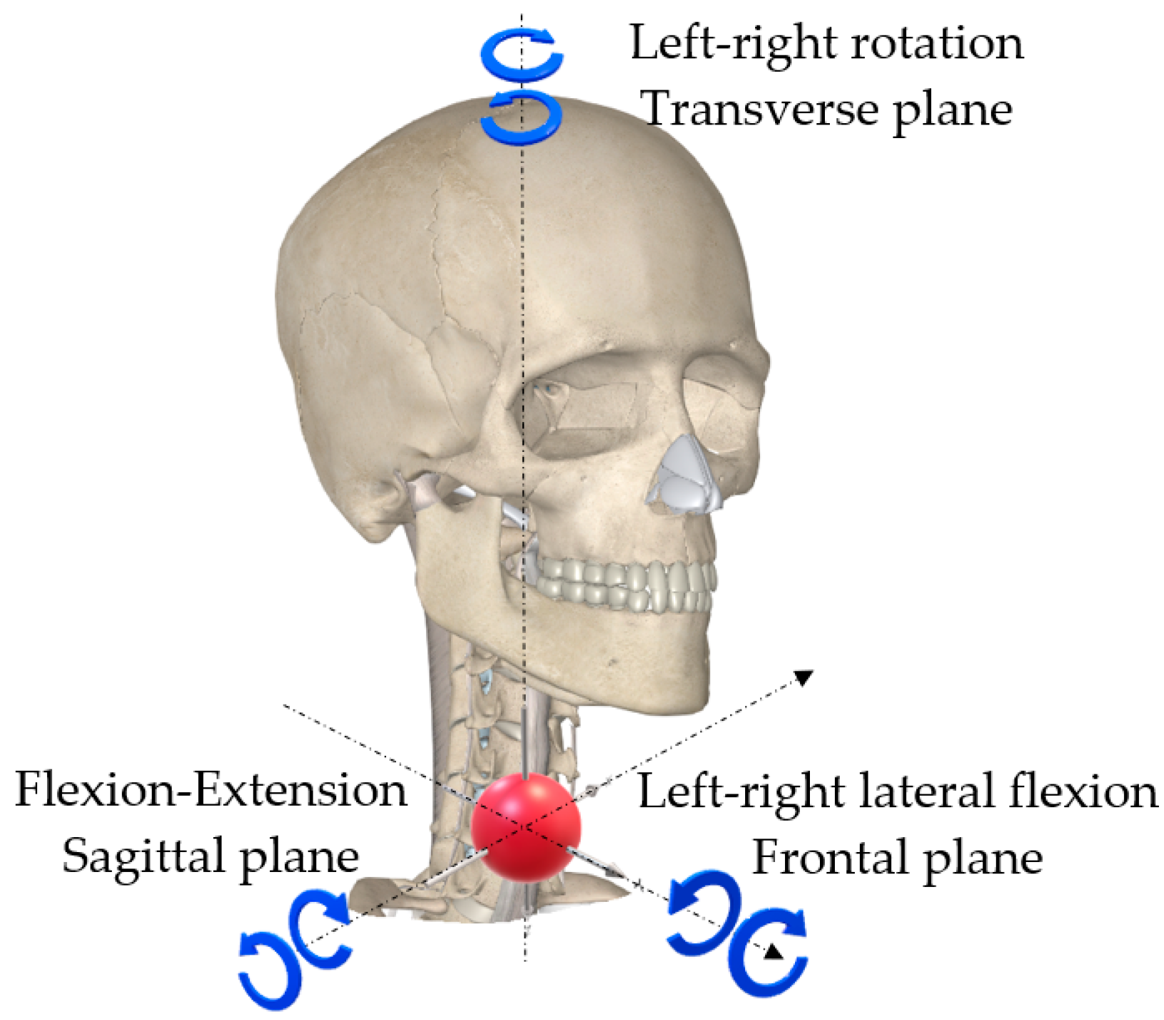
The movements of the neck joint in the three anatomic planes: frontal, sagittal and transverse are shown in Figure 1, while in Table 1 the angular amplitudes of these movements are centralized:

Figure 1.
Movements of the neck joint.

Table 1.
Movements of the neck joint and their limits.
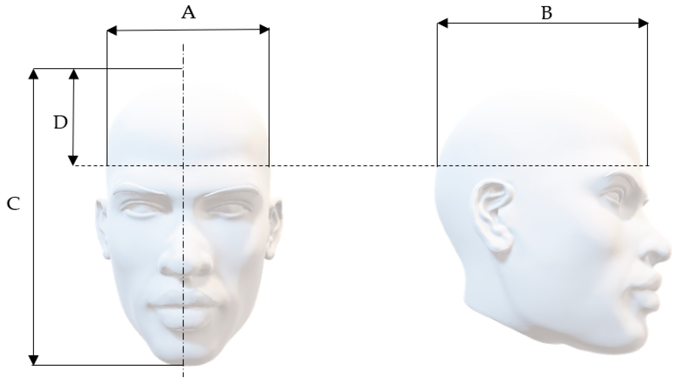
This paper aims to present a solution for a piece of rehabilitation equipment of the neck joint in the sagittal and frontal planes, and consequently only the movements in these planes will be analyzed. The design of the neck joint rehabilitation equipment in the sagittal and frontal planes is based on the anthropometric parameters (indices) of the human head. In the case of this joint of interest are the mass, cranial perimeter, the dimensions of the head in the three anatomic planes, etc. Statistically determined, the mass of the adult human head is of approximately 5 kg [17]. Regarding the average circumference of the human head, a study conducted in the United States estimated it to 57 cm in males and 55 cm in females [18]. In paper [19] Newcastle University reports a study that yields an average head circumference of 57.2 cm in males and 55.2 cm in females. Other data concerning the average dimensions of the human head are summarized in Table 2 and Figure 2 [20].
Table 2.
Anthropometric indices of the human head and neck.

Figure 2.
Anthropometric measurements of the human head.
Determining the forces and torques developed by the neck joint is of the essence for dimensioning the proposed rehabilitation equipment. The torques generated by the rotation in the sagittal and frontal planes of the neck joint are of about 12 N∙m and 20 N∙m, respectively [21,22,23]. The torques vary over the range of rotation angles of the joint. The previously specified values are the maximum ones to be ennsured by the equipment.
3. Operational Principle of the Rehabilitation Equipment for the Sagittal and Frontal Plane Movements of the Neck Joint
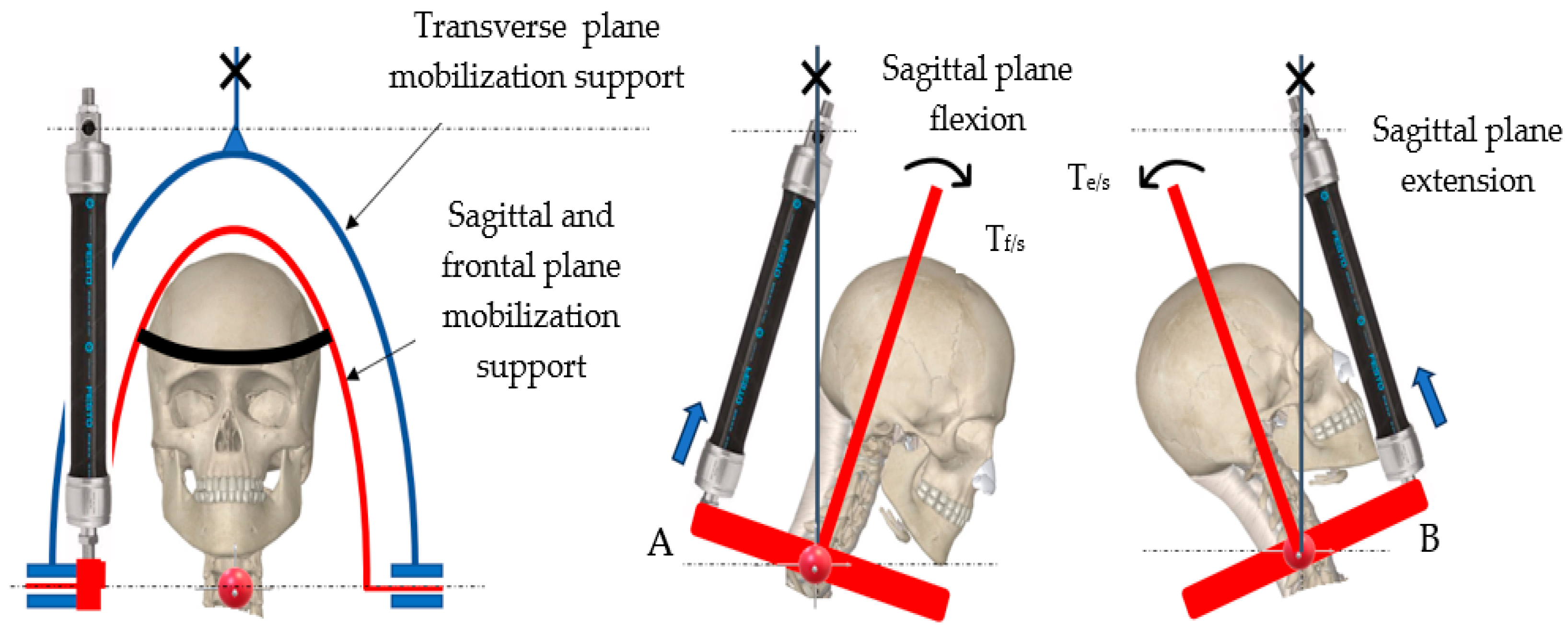
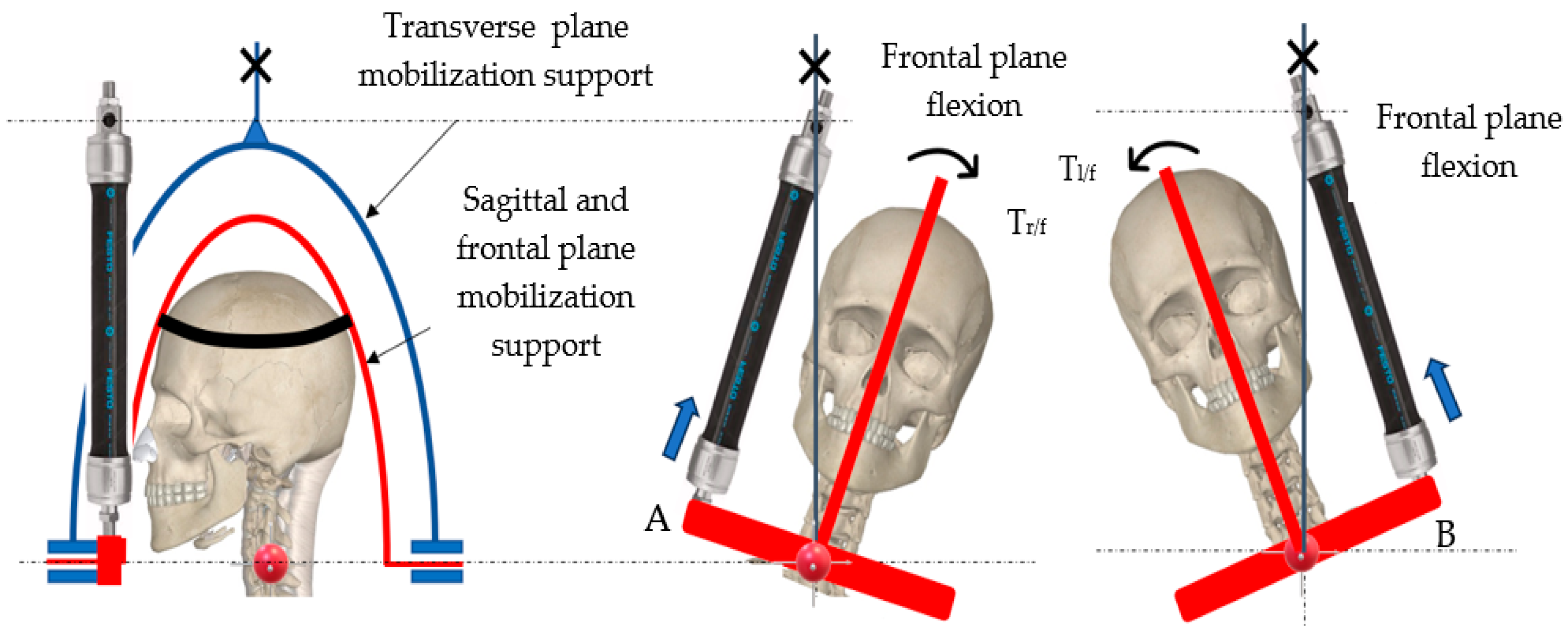
The proposed kinematic diagram for performing the movements in the two anatomic planes is shown in Figure 3 and Figure 4.

Figure 3.
Generating flexion/extension in the sagittal plane.

Figure 4.
Generating lateral right/left flexion in the frontal plane.
The rotation axis in the two studied anatomical planes is positioned at the interface of vertebrae C4 and C5 [21,22,23].
The movements of the neck joint are carried out exclusively by the interior mobilization support of the rehabilitation equipment (marked red in the figures above). This support is rotated by means of a single pneumatic muscle of DMSP-20-300N-RM-CR type (manufactured by Festo, Esslingen, Germany), whose dimensions are: interior diameter = 20 mm; length of the active part = 300 mm. The axial contraction of this muscle when charged at a pressure of 6 bar is of ΔLmax = 60 mm (20% of its initial length).
The ends of the horizontal lever of the mobilization support in the sagittal and frontal planes are denoted by A and B. Regardless of the plane of movement, the free end of the pneumatic muscle is connected to one of the ends of the support. End A is used in the case of flexion in the sagittal plane or of lateral right flexion in the frontal plane, while end B is used for extension in the sagittal plane or lateral left flexion in the frontal plane.
The limits of the respective movements that have to be reached in the two planes are shown in Table 1, namely:
- In the sagittal plane: flexion: 50°; extension: 60°.
- In the frontal plane: lateral left/right flexion: ±45°.
4. Dimensioning the Movement Generation System in the Sagittal and Frontal Planes
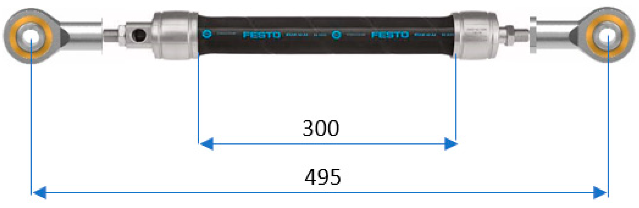
The rotation by an angle ω in one or the other direction in the two anatomic planes takes place when the pneumatic muscle is charged with air at different pressures. The variation of the feed pressure in the muscle causes modification of its length as well as of the developed forces. The connections of the pneumatic muscle to the mobilization support in the (fixed) transverse plane on one hand and to the mobilization support in the (mobile) sagittal and frontal plane, respectively is achieved by means of two spherical joints. Figure 5 shows the assembly of the muscle and the two joints:

Figure 5.
Pneumatic muscle–spherical joints assembly.
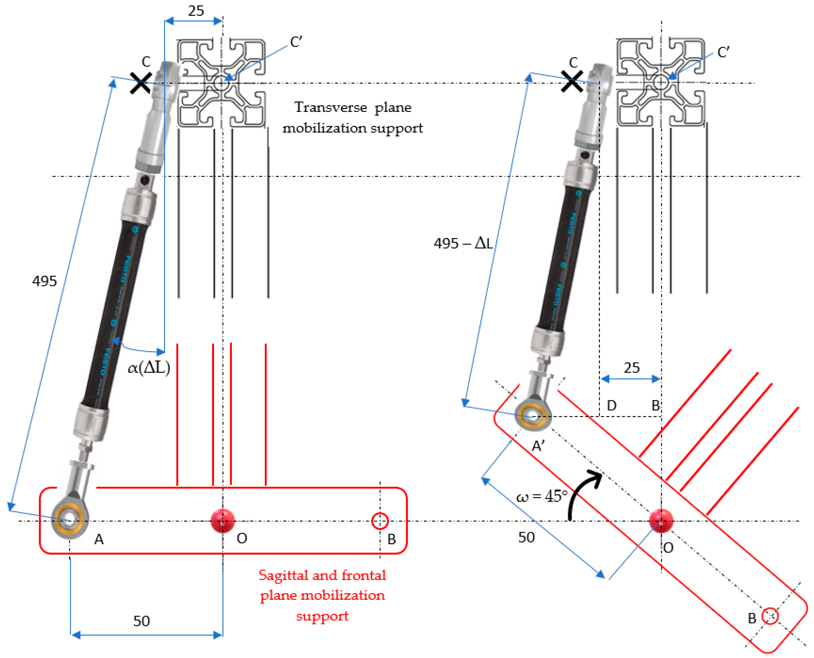
The rotation principle of the mobilization support in the sagittal and frontal planes is shown in Figure 6:

Figure 6.
Rotation principle of the mobilization support in the sagittal and frontal planes.
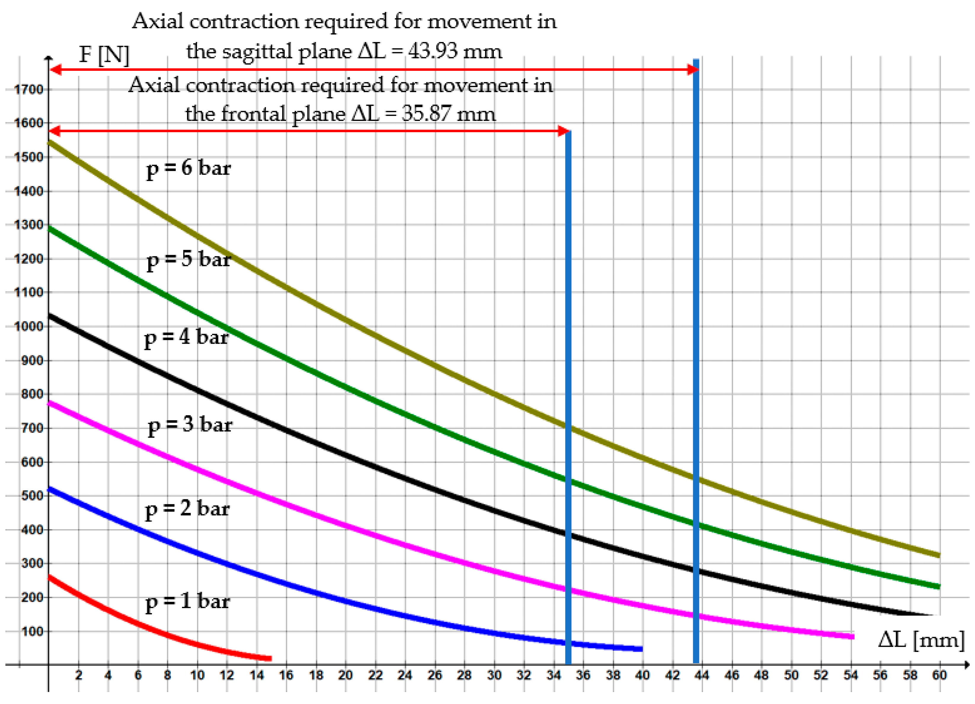
The maximum forces that can be developed by the selected pneumatic muscle are obtained by means of MuscleSim v. 2.0.1.5 program, and the variation diagram of such forces versus compressed air pressure and axial contraction is shown in Figure 7:
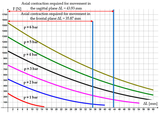
Figure 7.
Variation of the force developed by the pneumatic muscle DMSP-20-300N-RM-CR.
Upon carrying out some elementary geometrical calculations it follows that in order to rotate by an angle of ω = 45° necessary for movement in the frontal plane, the axial contraction of the pneumatic muscle has to be: ΔL = 495 − 459.13 = 35.87 mm. This axial contraction of the pneumatic muscle can be reached by feeding it with compressed air at pressures between 2 and 6 bar. In Figure 7 the operational range is defined within that rotations of the mobilization support up to 45° are possible. Similarly, for movement in the sagittal plane by a maximum angle of ω = 60°, there results ΔL = 43.93 mm. Figure 7 shows the range of working pressures (3 … 6 bar) at that this angle can be obtained.
The necessary torque for rotation in both planes (sagittal and frontal) is calculated with Equation (1):
where F(ΔL) is the force developed by the pneumatic muscle as a function of its axial contraction, and a is the lever length that rotates the mobilization support. The mounting angle of the pneumatic muscle, α(ΔL), also depends on the axial contraction. As the angle α(ΔL) varies only slightly during operation and has small values (1.3 … 2.9°) it can be neglected. Thus, the previous equation becomes:
For the pneumatic muscle DMSP-20-300N-RM-CR fed at p = 6 bar, the dependency of the force on the axial contraction is obtained by Graph v.4.4.2 application, namely:
Upon replacing Equation (3) in (2) and considering a = 0.05 m it follows that:
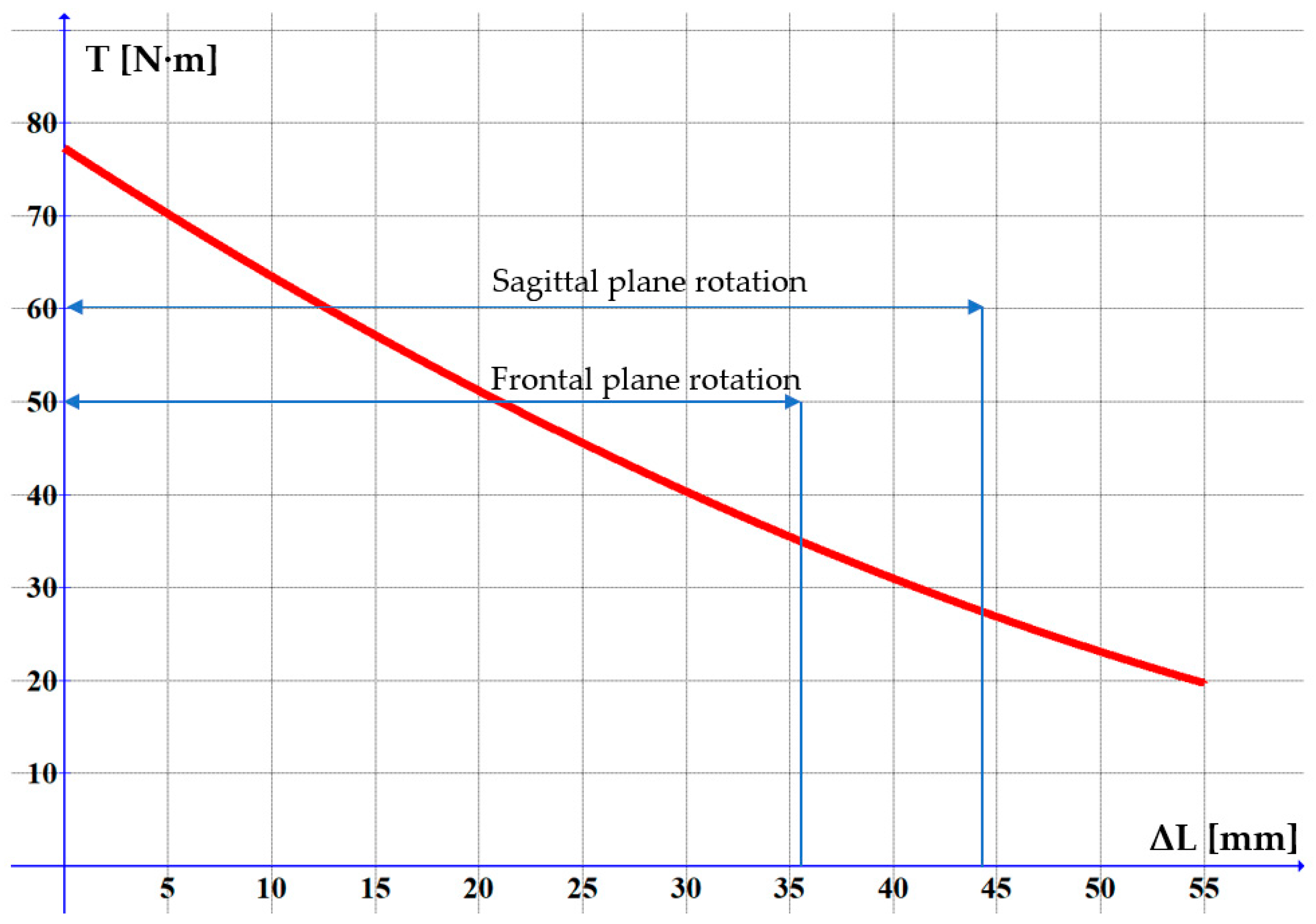
The graph of this equation is presented in Figure 8. Figure 9 shows the variation of the torque versus the rotation angle of the neck joint:

Figure 8.
Variation of the torque versus the axial contraction of the pneumatic muscle.

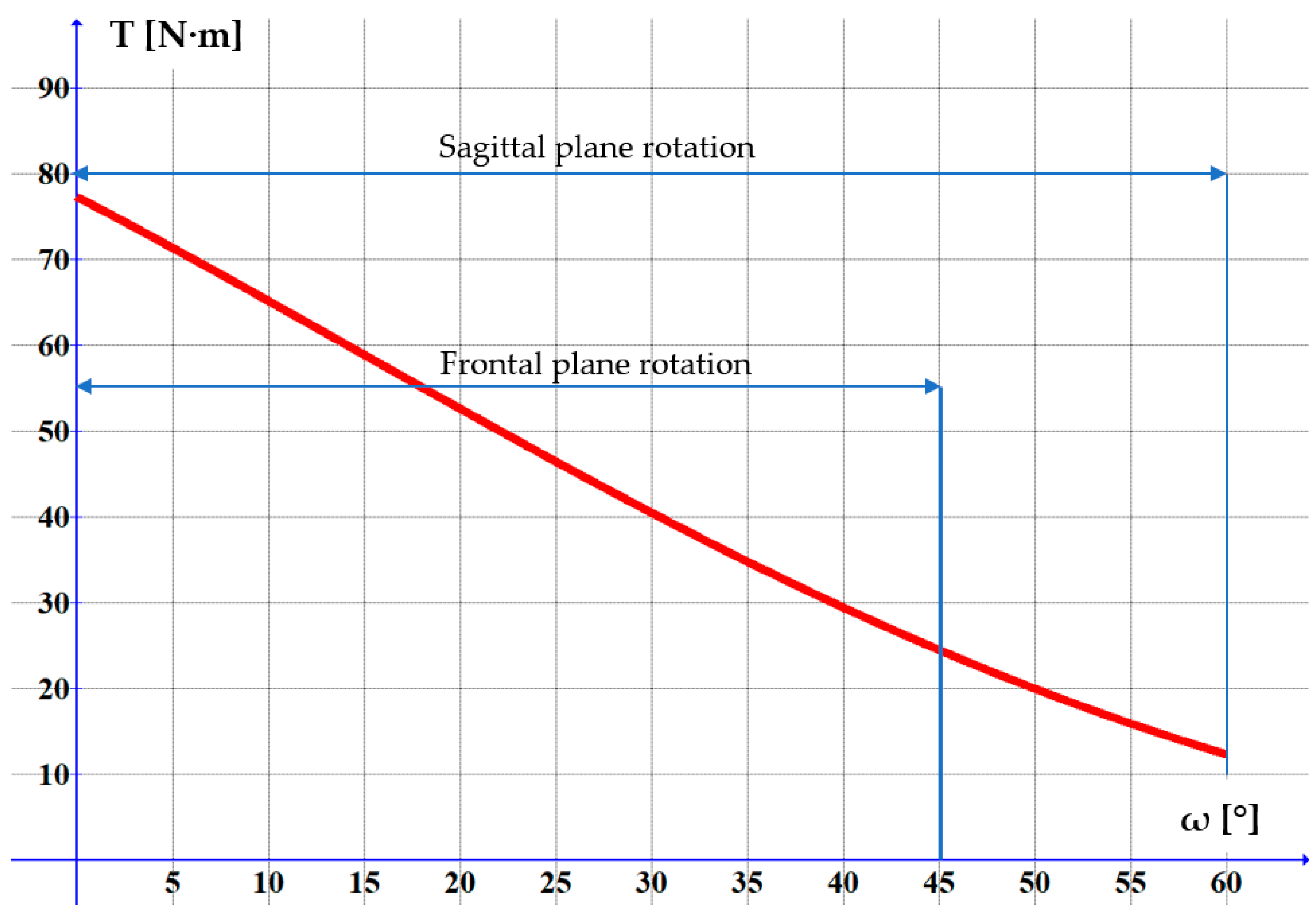
Figure 9.
Variation of the torque versus the rotation angle of the neck joint in the sagittal/frontal plane.
By means of the Graph application Equation (5) is obtained:
At 6 bar feed pressure the maximum force developed by the muscle is of 703.1 N (from the MuscleSim application provided by de Festo). In this case the torque developed for the movement in the frontal plane is of 24.52 N∙m > 20 N∙m, and of 12.35 N∙m > 12 N∙m for the movement in the sagittal plane.
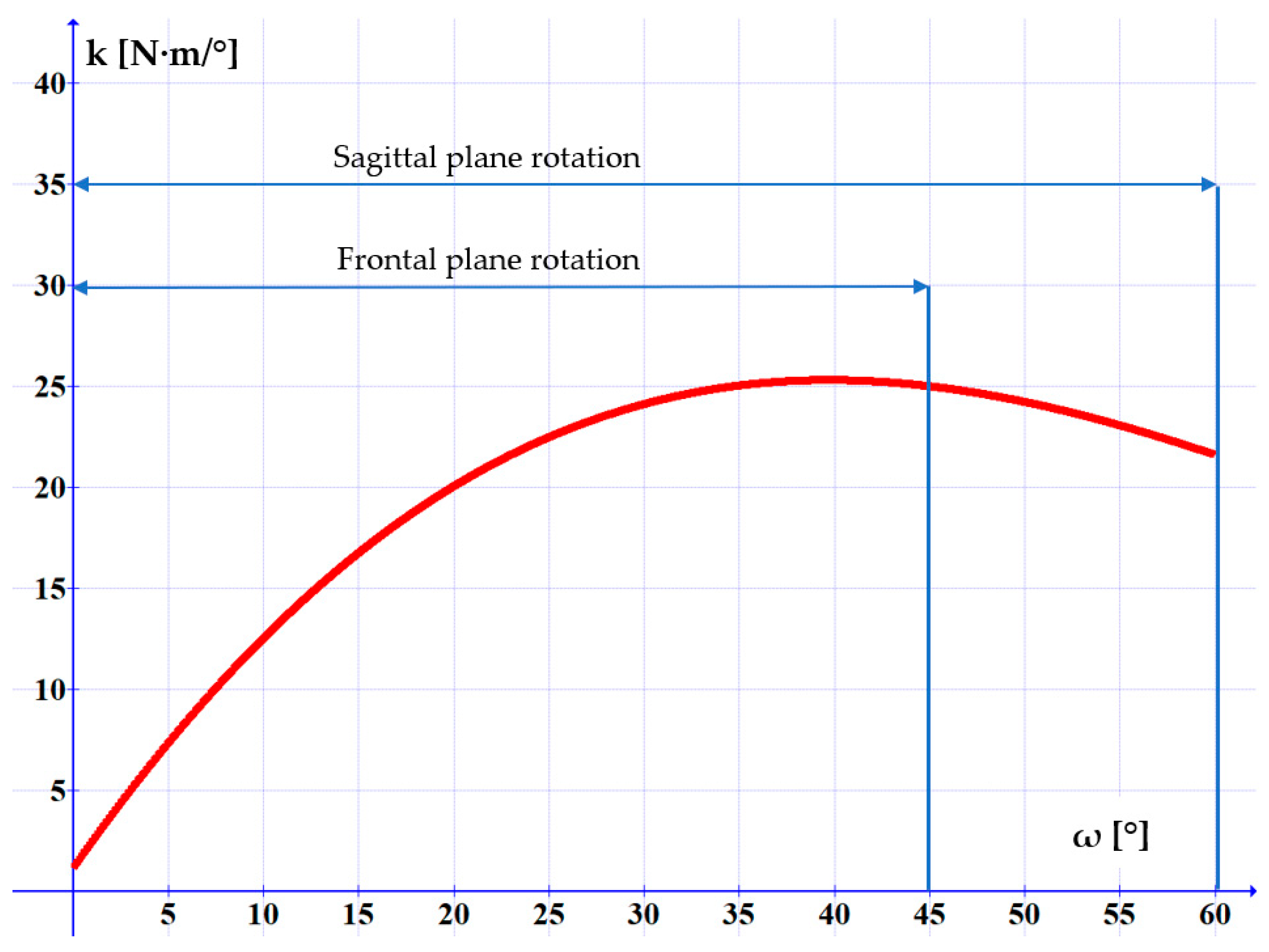
The torsional rigidity of this joint is calculated by Equation (6) and Figure 10 shows its dependency on angle ω.

Figure 10.
Variation of the torsional rigidity versus the rotation angle of the neck joint.
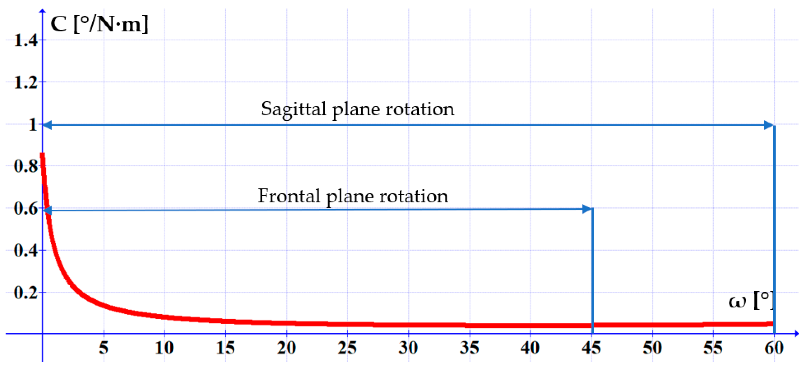
The torsional compliance is calculated by Equation (7), and was graphically represented in Figure 11:

Figure 11.
Variation of the torsional compliance versus the rotation angle of the neck joint.
It can be noticed, that as the rotation angle increases, the system’s compliance diminishes, initially at a high rate, then tending asymptotically towards minimum values as the angle exceeds 10°.
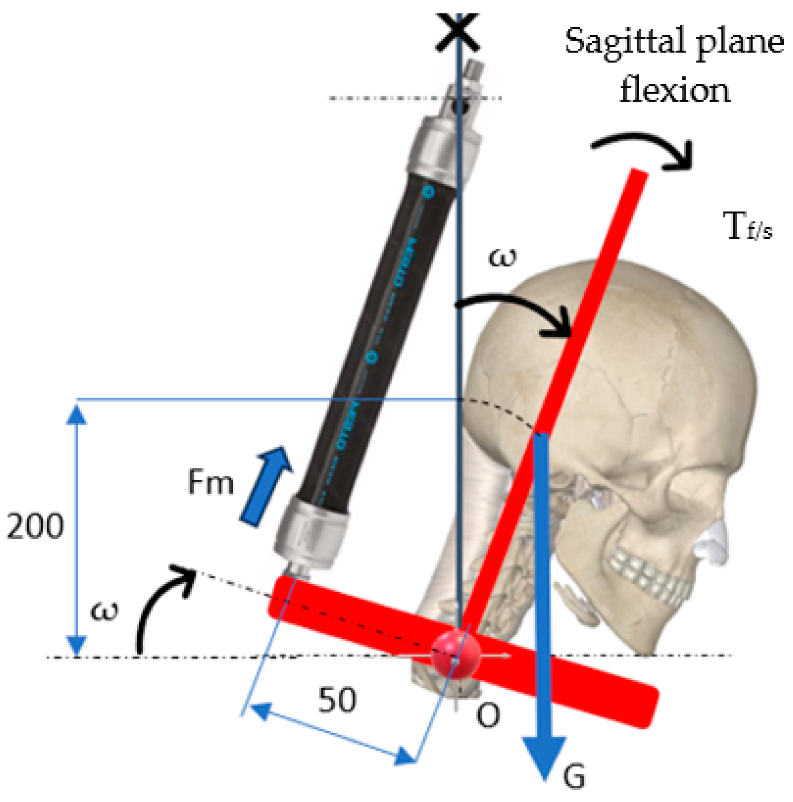
The study of rotation movements in the sagittal and/or frontal plane the so-called “gravitational test” has to be carried out that considers the influence of the weight of the moving masses. Figure 12 shows the schematic used for calculations. The weight of the mobile assembly is the sum of the weights of the head and the mobilization support [G = (5 + 1.46)·9.81 = 63.37 N]. These data are used to write the equilibrium equation of the torques developed by the pneumatic muscle on one hand and by the weight of the equipment’s mobile elements on the other.

Figure 12.
The effect of the moving weights on the rotating module (system).
Upon replacing G = 63.37 N in the above equation there follows:
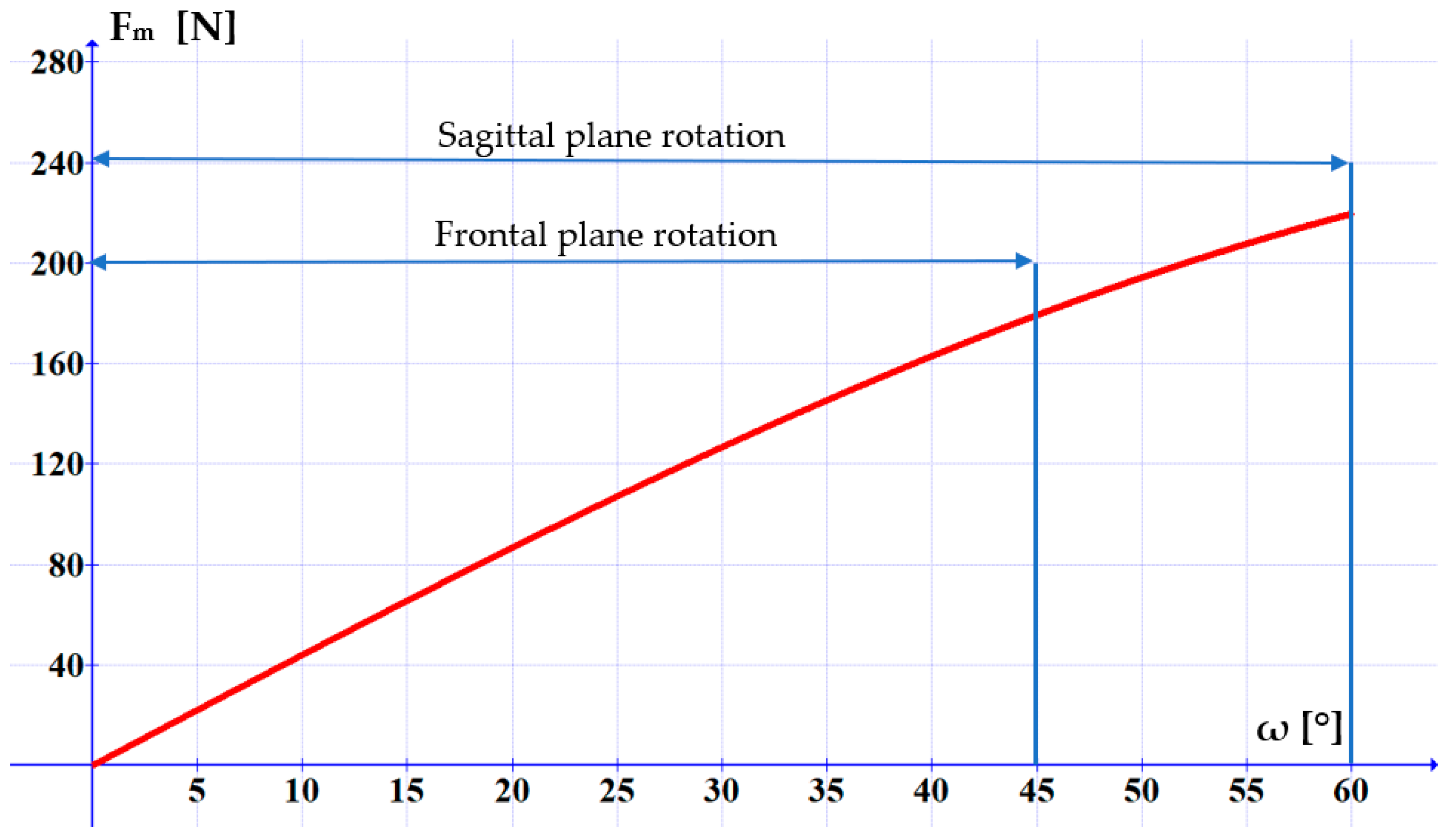
Figure 13 presents the variation of the force generated by the pneumatic muscle versus the rotation angle of the mobile assembly.

Figure 13.
Variation of the force to be generated by the pneumatic muscle in order to rotate the mobile assembly of the equipment.
It can be noticed that the maximum force that has to be developed by the pneumatic muscle in the frontal plane movement is of 180 N. This force is necessary for tilting the head at an angle of ω = 45°. For a tilt of ω = 60° the necessary force is of 220 N. In Figure 7 it can be observed that the selected pneumatic muscle meets this requirement at a compressed air pressure of 4…6 bar.
5. Discussion
The rehabilitation equipment for the sagittal and frontal plane movements of the neck joint has to meet two operational requirements simultaneously: high positioning precision and advanced adaptability to the patient’s pain tolerance. This latter requirement entails an adjustable compliance of the actuation system. Concerning these aspects the graphs of the torsional rigidity and compliance lead to two important conclusions:
- the precise achieving of certain rotation angles and firmly maintaining these requires a high rigidity of the rehabilitation equipment. Figure 10 highlights that the torsional rigidity increases with the rotation angle and that the most rigid behavior manifests in the range of ω = 25…60°;
- the high adaptability of the rehabilitation equipment to the patient’s state requires the intervention of adjustable compliance, as follows from Figure 11. The noticeable positive aspect of this constructive solution is its high compliance in the debut phase of the rehabilitation exercise, which is exactly when the patient’s fear of pain and the stiffness of the joint have to be overcome.
The two requirements outlined above are contradictory, thus complicating the possibility of meeting them simultaneously. For this reason, a compromise is called for: at the beginning of the rehabilitation exercising a high compliance has to be prioritized, while subsequently more important is to achieve and maintain precise positioning angles.
In terms of the equipment’s safety, the structure of the proposed equipment allows applying the optimum rehabilitation motions to the affected segment of the human body. Regarding the risks patients could be exposed to during testing, such are negligible to a degree of non-existent, given the reduced values of the motion speed and of the actuation forces.
6. Conclusions
This paper has presented a novel solution of rehabilitation equipment for the sagittal and frontal plane movements of the neck joint actuated by a pneumatic muscle. The deployment for actuation purposes of pneumatic muscles that benefit from an inherently compliant behavior ensures the adaptability of the rehabilitation equipment to the concrete circumstances of patient pain tolerance.
The proposed rehabilitation equipment enables rotation movements in the frontal and sagittal plane within the angular limits of the healthy human body, ensuring precise rotation angles and a compliant behavior.
The constructive solution and the operational principle have been described and the torque variation versus the axial contraction of the pneumatic muscle and the rotation angle of the neck joint in the two anatomic planes was calculated. The torsional rigidity and compliance have been determined, and based on the obtained results recommendations have been formulated regarding the optimum deployment of the rehabilitation equipment.
The paper has presented the results of the theoretical study concerning the conception of the pneumatically actuated rehabilitation equipment. The performance characteristics presented in the paper are related to the limits of the movements, the forces and torques, as well as to the torsional compliance, and were obtained only theoretically. At present the prototype of the neck joint rehabilitation system is under construction. Lab tests will be performed on the final prototype, and upon refining the constructive solution, testing will be conducted on human subjects. For this reason, at this time we cannot report experimental results.
Author Contributions
Conceptualization, S.M. and T.D.; methodology, T.D.; validation, A.D.; writing—original draft preparation, S.M. and A.D.; writing—review and editing, S.M., A.D. and T.D.; supervision, T.D. All authors have read and agreed to the published version of the manuscript.
Funding
This research received no external funding.
Institutional Review Board Statement
Not applicable.
Informed Consent Statement
Not applicable.
Data Availability Statement
Data are contained within the article.
Conflicts of Interest
The authors declare no conflicts of interest.
References
- Cervical Spine. Available online: https://my.clevelandclinic.org/health/articles/22278-cervical-spine (accessed on 7 December 2024).
- Nunes, I.L.; Bush, P.M. Work-Related Musculoskeletal Disorders Assessment and Prevention. Available online: https://www.intechopen.com/chapters/35811 (accessed on 7 December 2024).
- Simoneau, S.; St-Vincent, M.; Chicoine, D. Work-Related Musculoskeletal Disorders. A Better Understanding for More Effective Prevention; Institut de Recherche Robert Sauvé en Santé et en Sécurité: Quebec, QC, Canada, 1996. [Google Scholar]
- de Kok, J.; Vroonhof, P.; Snijders, J.; Roullis, G.; Clarke (Panteia), M.; Peereboom, K.; van Dorst, P.; Isusi, I. Work-Related Musculoskeletal Disorders: Prevalence, Costs and Demographics in the EU; European Risk Observatory Report; European Agency for Safety and Health at Work: Luxembourg, 2019. [Google Scholar]
- Pratama, A.D.; Farelin, A.D.; Karnadipa, T.; Pahlawi, R.; Noviana, M.; Abdullah, F. The Application of Telerehabilitation for Pain Reduction and Improving Quality of Life in Workers with Work-Related Musculoskeletal Disorders: Systematic Review. Proceedings 2022, 83, 45. [Google Scholar] [CrossRef]
- Work-Related Musculoskeletal Disorders (WMSDs). Available online: https://www.ccohs.ca/oshanswers/diseases/rmirsi.html (accessed on 7 December 2024).
- Deaconescu, T.; Deaconescu, A. Pneumatic Muscle Actuated Equipment for Continuous Passive Motion. AIP Conf. Proc. 2009, 1174, 311–321. [Google Scholar]
- Doss, A.S.A.; Lingampally, P.K.; Nguyen, G.M.T.; Schilberg, D. A comprehensive review of wearable assistive robotic devices used for head and neck rehabilitation. Results Eng. 2023, 19, 101306. [Google Scholar] [CrossRef]
- David Health Solutions. Cervical Muscles Exerciser G160. Available online: https://www.medicalexpo.com/prod/david-health-solutions/product-92425-836086.html (accessed on 8 December 2024).
- David Health Solutions. G140 Cervical Extension/Lateral Flexion Device. Available online: https://davidhealth.com/global-content/cervical-extension/ (accessed on 8 December 2024).
- Shoaib, M.; Lai, C.Y.; Bab-Hadiashar, A. A Novel Design of Cable-Driven Neck Rehabilitation Robot (CarNeck). In Proceedings of the IEEE/ASME International Conference on Advanced Intelligent Mechatronics (AIM), Hong Kong, China, 8–12 July 2019; pp. 819–825. [Google Scholar] [CrossRef]
- Kim, H.; Park, H.; Lee, W.; Kim, J.; Park, Y.L. Design of wearable orthopedic devices for treating forward head postures using pneumatic artificial muscles and flex sensors. In Proceedings of the 14th International Conference on Ubiquitous Robots and Ambient Intelligence (URAI 2017), Jeju, Republic of Korea, 28 June–1 July 2017. [Google Scholar]
- Yue, D.A.I.; Ping, S.; Hongyu, Z.; Sujiao, L.; Fanfu, F. Design and kinematics analysis of powered cervical exoskeleton based on human biomechanics. J. Univ. Shanghai Sci. Technol. 2022, 44, 18–26. [Google Scholar]
- Multi-Cervical Unit (MCU). Available online: https://www.btetechnologies.com/products/functional-rehabilitation/multi-cervical-unit/ (accessed on 29 July 2024).
- DBC Active Treatment Devices. Available online: https://www.dbc.fi/additional-device-information (accessed on 29 July 2024).
- Xu, Y.; Ju, K.; Zhang, C. A Wrist-Inspired Magneto-Pneumatic Hybrid-Driven Soft Actuator with Bidirectional Torsion. Cyborg Bionic Syst. 2024, 5, 0111. [Google Scholar] [CrossRef] [PubMed]
- Human Head. Wikipedia. Available online: https://en.wikipedia.org/wiki/Human_head (accessed on 8 December 2024).
- Ching, R.P.; (Applied Biomechanics Laboratory, University of Washington, Washington, DC, USA). Technical Brief—Relationship Between Head Mass and Circumference in Human Adults. 20 July 2007.
- Bushby, K.M.; Cole, T.; Matthews, J.N.; Goodship, J.A. Centiles for adult head circumference. Arch. Dis. Child. 1992, 67, 1286–1287. [Google Scholar] [CrossRef] [PubMed]
- Mareş, S.; Deaconescu, A.; Deaconescu, T. Pneumatically Actuated Torsion Motor for the Transverse Rehabilitation of the Neck Joint. Actuators 2024, 13, 363. [Google Scholar] [CrossRef]
- Berg, H.E.; Berggren, G.; Tesch, P.A. Dynamic neck strength training effect on pain and function. Arch. Phys. Med. Rehabil. 1994, 75, 661–665. [Google Scholar] [CrossRef] [PubMed]
- Choi, H.; Vanderby, R. Comparison of biomechanical human neck models: Muscle forces and spinal loads at C4–C5 level. J. Appl. Biomech. 1999, 15, 120–138. [Google Scholar] [CrossRef]
- Vasavada, A.N.; Li, S.; Delp, S.L. Three-dimensional isometric strength of neck muscles in humans. Spine 2001, 26, 1904–1909. [Google Scholar] [CrossRef] [PubMed]
Disclaimer/Publisher’s Note: The statements, opinions and data contained in all publications are solely those of the individual author(s) and contributor(s) and not of MDPI and/or the editor(s). MDPI and/or the editor(s) disclaim responsibility for any injury to people or property resulting from any ideas, methods, instructions or products referred to in the content. |
© 2025 by the authors. Licensee MDPI, Basel, Switzerland. This article is an open access article distributed under the terms and conditions of the Creative Commons Attribution (CC BY) license (https://creativecommons.org/licenses/by/4.0/).