Article

Implementation of ANN Controller Based UPQC Integrated with Microgrid

1
Department of Electrical Engineering, Sukkur IBA University, Sukkur 65200, Pakistan
2
Department of Electrical Engineering, College of Engineering, Prince Sattam Bin Abdulaziz University, Al-Kharj 16273, Saudi Arabia
3
Department of Electrical Power and Machines Engineering, Faculty of Engineering, Helwan University, Helwan 11795, Egypt
4
Electrical Engineering Department, Faculty of Engineering, Aswan University, Aswan 81542, Egypt
5
The Villum Center for Research on Microgrids (CROM), AAU Energy, Aalborg University, 9220 Aalborg East, Denmark
*
Author to whom correspondence should be addressed.
Mathematics 2022, 10(12), 1989; https://doi.org/10.3390/math10121989
Submission received: 13 April 2022 / Revised: 15 May 2022 / Accepted: 6 June 2022 / Published: 9 June 2022
(This article belongs to the Section Mathematics and Computer Science)

Abstract

:
This study discusses how to increase power quality by integrating a unified power quality conditioner (UPQC) with a grid-connected microgrid for clean and efficient power generation. An Artificial Neural Network (ANN) controller for a voltage source converter-based UPQC is proposed to minimize the system’s cost and complexity by eliminating mathematical operations such as a-b-c to d-q-0 translation and the need for costly controllers such as DSPs and FPGAs. In this study, nonlinear unbalanced loads and harmonic supply voltage are used to assess the performance of PV-battery-UPQC using an ANN-based controller. Problems with voltage, such as sag and swell, are also considered. This work uses an ANN control system trained with the Levenberg-Marquardt backpropagation technique to provide effective reference signals and maintain the required dc-link capacitor voltage. In MATLAB/Simulink software, simulations of PV-battery-UPQC employing SRF-based control and ANN-control approaches are performed. The findings revealed that the proposed approach performed better, as presented in this paper. Furthermore, the influence of synchronous reference frame (SRF) and ANN controller-based UPQC on supply currents and the dc-link capacitor voltage response is studied. To demonstrate the superiority of the suggested controller, a comparison of percent THD in load voltage and supply current utilizing SRF-based control and ANN control methods is shown.

1. Introduction

It is not easy to maintain power quality measures by incorporating and using vast electronic technologies such as electronic controllers, switches, computer power supplies, adjustable speed drives, etc. [1,2]. These devices have an impact on sinusoidal voltage and current magnitude at different load conditions leading to the reduction in efficiency of power networks and equipment connected to the system [3]. Passive power filters, active power filters, and flexible AC transmission system (FACTS) controllers are often used to get rid of power quality events. Passive power filters were designed to mitigate the issues related to these electronic devices. However, these result in system bulkiness and resonance, indicating the need for an alternative solution. Therefore, active power filters were introduced to resolve problems without creating resonance and increment in the size of the system. Nevertheless, these are more expensive as compared to passive power filters. Active power conditioners (APC), active voltage conditioners (AVC), dynamic voltage restorers (DVR), and distribution static synchronous compensators (DSTAT-COM) are among the FACTS controllers used to improve power quality owing to disturbances such as voltage sag/swell, non-linearity, and harmonics [4,5]. According to current research, a unified power quality conditioner (UPQC) is a low-cost custom power device (CPD) linked at the point of common coupling (PCC) that protects power supply units and consumers from power quality changes [6]. A unified power quality conditioner (UPQC) is a power-conditioning device used to prevent undesired power quality events such as voltage sag/swell, non-linearity, and harmonics on both the grid and consumer sides. It has a common dc interface that connects series and shunts active power filters. Harmonics of load side current are eliminated using shunt APFs. Series APFs, on the other hand, compensate for voltage sags, swells, and flickers in source voltage. Reference [7] provides a clear and detailed overview of UPQC. The performance of UPQC is determined by the control algorithm used to generate current and voltage reference signals, which are then used by inverters to carry out critical control operations [5]. Control algorithms such as instantaneous active-reactive (IAR) power theory, synchronous reference frame (SRF) theory, unit vector template (UVT) generation, fast Fourier transform (FFT), discrete wavelet transform (DWT), and exponential composition algorithm (ECA) are used to generate reference signals in UPQC [5]. The performance of UPQC is determined by the precision and speed with which reference signals are created [3]. Reference [8] incorporates an IAR power theory for providing current and voltage reference signals for inverters. At cut-off frequencies, the approach clamps down on the offset value of dc to zero. Reference [9] developed the Synchronous reference frame theory for the creation of reference signals, which uses (HPF) or (LPF) to remove the dc signal. However, this strategy has a detrimental influence on controller dynamics, as well as a constraint on cut-off frequencies. In reference [10], a unit vector templet approach was used to generate reference signals. However, UVT needs a complicated phase-locked loop (PLL) that acts as a frequency sequencer. In reference [11], a control technique based on FFT was used to eliminate the undesired events that occurred in load current and source voltage. However, this approach is only accurate in steady-state. Reference [12] employs a DWT-based technique that uses least squares to remove frequency, phase angle, and basic component amplitude. The exponential composition algorithm (ECA) is tested using digital circuits in reference [13]. The method is simple to implement, reduces THD levels to IEEE standards, and employs a simple mathematical model.
In recent years, much effort has been put into developing intelligent and unconventional control strategies that can expand and shrink standard control systems. Many novel control approaches have been created, providing answers to various challenging control problems in the manufacturing and industrial sectors. These unique controllers are not like their conventional counterparts in any way. They can learn, remember, and make decisions. An ANNMPC-based UPQC has been proposed in [14] to eliminate harmonics caused in the distribution network in order to improve power quality. Representation of the system is executed by MATLAB/SIMULINK platform, and the results have been presented. The design of an intelligent artificial neuro fuzzy-based UPQC controller has been proposed in [15] to improve power quality. Artificial intelligence (AI) techniques, especially NNs, have a notable impact on power-electronics applications. To boost the dynamic performance of UPQC, an ANN based admittance estimation strategy (ANN-ADES) has been presented in [16]. The model has been implemented using MATLAB and an FPGA board for compensating the voltage sag/swell, unbalanced load conditions, and harmonic eliminations. Nevertheless, the strategy is applicable where load periodicity is not constant. A Multi-level diode clamped converter (DCC) ANN-based UPQC has been evaluated with distorted supply voltage and unbalanced non-linear loads in [17,18] to eliminate the mathematical model and complex controllers. An ANN-based controller for current control of shunt APF has been presented in [3] to replace the PI controller over the ANN controller to encounter voltage related issues.
Furthermore, multi-objective systems have recently been the focus of research. There is a demand for renewable energy systems that can increase power quality while also operating when the grid is unavailable. Solar PV is one of the most important contributions to renewable energy generation since it is inexpensive and environmentally safe. In reference [1], a three-phase PV-UPQC was investigated under different irradiation and voltage sag/swell conditions. An automated transition of solar PV-battery integrated UPQC between standalone and grid-connected operation modes has been represented and examined [19]. Reference [20] describes an enhanced step-up converter with a created real-time fuzzy-based MPPT controller for PV-based residential applications, although it has a complicated design. For tracking purposes, the P&O Technique is employed as it is simple and accurate for extracting maximum power from the PV array [21].
The neural network-based controller provides a quick dynamic response while maintaining converter system stability over a wide operating range. It is considered the latest tool for control circuit design for power quality improvement. Significant studies on control circuit design for UPQCs have been conducted in recent years with the goal of creating robust control algorithms and fast response methods to provide switching control signals [3]. The PV system using ANN-based UPQC has been used in [22] to maintain smooth operation during low voltage ride through (LVRT) and improve power quality. The time-frequency analysis method based on ANN with SWT has been presented in [5] to identify, detect, and control power quality issues in a distribution system integrated with a micro grid. An ANFIS based adaptive control method has been presented in [6] to mitigate power quality distortion by integrating a grid-connected micro-grid using UPQC devices. For addressing symmetrical/unsymmetrical source, balanced and unbalanced load, ANFIS based PV-integrated UPQC has been presented in [15]. In PQ and Synchronous reference frame theory (SRF) based control, the transformations a-b-c to a-b-0, a-b-c to d-q-0, and their inverse transformations are utilized, respectively. The usage of DSPs and FPGAs is recommended to create sophisticated controllers with huge memory. On the other hand, these controllers are faster at performing mathematical calculations. However, they raise the entire system’s cost and complexity because they are complicated.
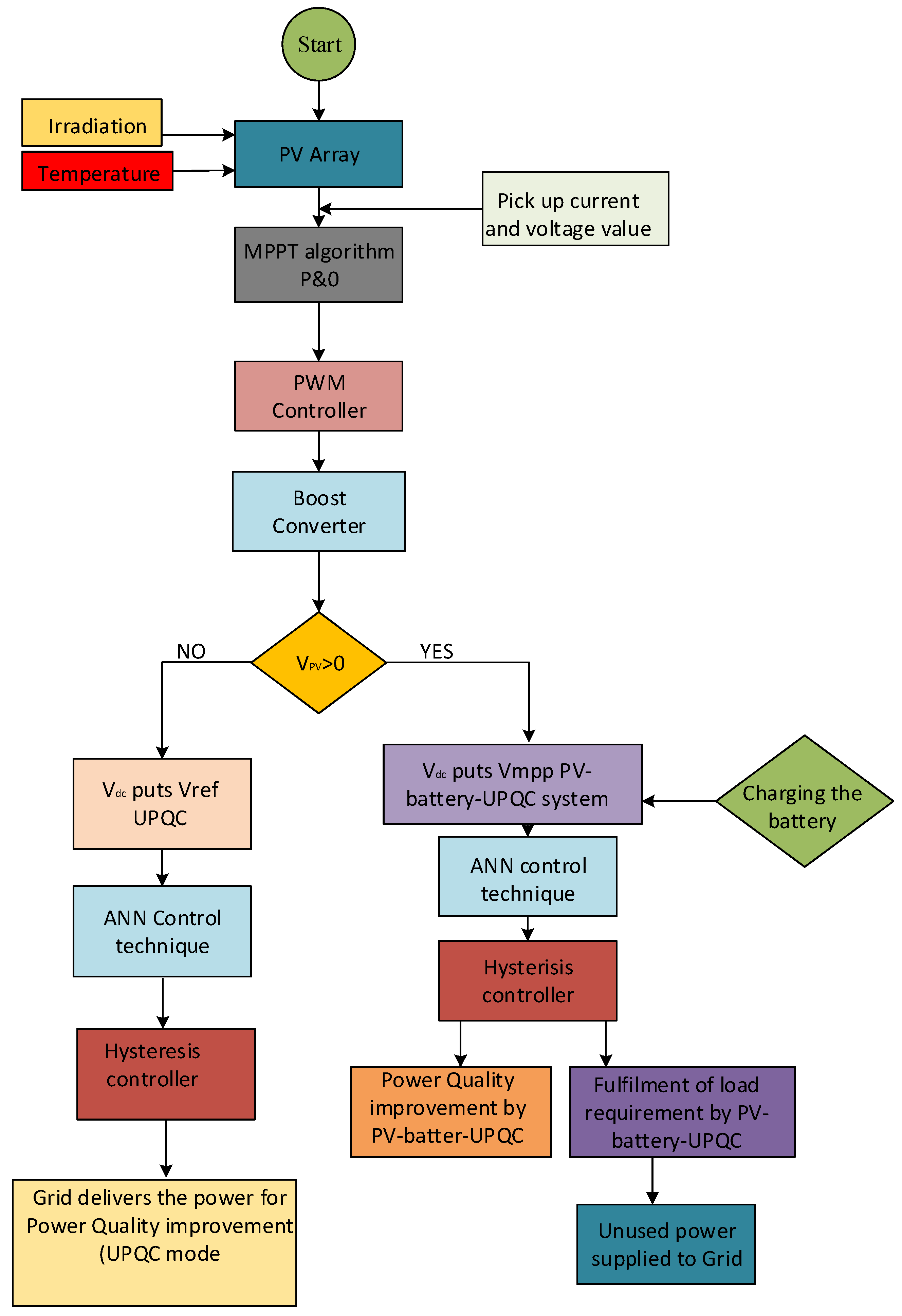
A quick and intelligent ANN-based control system for PV-battery based UPQC to regulate voltage sag, swell, and harmonics of grid-connected micro grid is suggested in this work. An ANN-based controller minimizes a system’s complexity and expense. Because it eliminates the mathematical process, it may be implemented with a basic microcontroller, lowering the system’s cost and complexity. This suggested approach compensates for fluctuations in the system’s supply voltage and loads current at the same time. The system discussed here has been created in the MATLAB Simulink environment. The system is divided into three stages. The first stage employs a DC-DC boost converter to implement the P&O algorithm for MPPT. The second stage employs the SRF technique for shunt active power filter and series active power filter, and the third stage employs the ANN technique for shunt active power filter and series active power filter. The key contributions of this paper are:
  • The combined control of a PV-Battery-UPQC based ANN control system.
  • Simultaneously voltage and current quality improvement using the proposed intelligent controller.
  • Comparison between synchronous reference frame (SRF) and Artificial neural network (ANN) based controller.
  • Designing and implementing an intelligent and cost-effective control technique for achieving better results for power quality improvement.
The paper is structured as follows: the configuration of the system integrated with UPQC & control methods of compared techniques are presented in Section 2, the designing parameters of the system are discussed in Section 3, and Section 4 illustrates the comprehensive discussions and the simulation results and, finally, conclusion and proposals for future work are included in Section 5.

2. Configuration of System Integrated with UPQC

The circuit diagram of the proposed grid tied-PV-battery-UPQC system is shown in Figure 1. A MPPT P&O algorithm is used for maximum power extraction from PV using a boost converter connected with three-phase voltage source inverters (VSI) at the point of PCC (point of common coupling). The VSI has six IGBT acting as switching devices between utility and DC-link. The performance of the system is optimized using an AINN-based control algorithm. Figure 2 represents the flowchart for the functioning of the grid-tied-PV-battery-UPQC system.

2.1. Maximum Power Point Tracking MPPT

As shown in Figure 3, the V-I characteristics of a PV array are non-linear and interact with solar radiation and temperature conditions. As a result, it must be monitored at full power. Therefore, the MPPT approach is used in conjunction with a DC-DC converter to extract the maximum power efficiency from the PV array. For DC-DC converter topologies, converters like boost, buck, and buck-boost are employed, but the boost converter is the most important since it stops the reverse current flow into the PV Array [8]. PV array characteristics like Voc and Isc are determined by external factors such as irradiance and temperature, and the output is measured in terms of duty cycle, which corresponds to the maximum power point utilized to drive the boost converter. The PWM module creates a signal that controls the IGBT switch’s duty cycle. The system’s inputs are open-circuit voltage and PV short circuit current, and the output is the duty cycle that gives reference voltage from PV.
In the above graph, varying parameters are shown where current is directly proportional to irradiation and voltage partially depends upon temperature conditions. Here 100 kW PV is taken for model simulations.

2.2. Control Algorithm of UPQC

2.2.1. Control Algorithm of UPQC Based on SRF

There are various control techniques used to generate reference signals for current and voltage. The SRF technique is used for providing a fast transient response [9].

Control Technique of Shunt Compensator

The active fundamental component of load current is extracted by the shunt compensator for load current compensation. To accomplish this, the shunt compensator is operated using the SRF technique. The synchronous basic d-q-0 frame is a time-domain approach derived from three-phase systems’ space vector transformations. While this strategy is appropriate for active filtering, this is because it obtains the non-sinusoidal current fundamental, which may be used to calculate the compensatory current [1,2]. Figure 4 depicts the shunt compensator’s control method, in which load currents are translated to the d-q-0 domain using frequency and phase data obtained from a PLL (phase-locked loop). The PCC voltage is the input of PLL. The d-component is filtered to achieve a filtered DC component which is counted as a fundamental component in terms of the synchronous reference frame. A low pass filter is used to extract the fundamental component of load current Ifl. The park’s-Clark’s transformation takes place for the transformation of fundamental signal extraction in SRF which is given as:
[ i d i q i 0 ] = 2 3 ( cos θ cos ( θ 2 π 3 ) cos ( θ + 2 π 3 ) sin θ sin ( θ 2 π 3 ) sin ( θ + 2 π 3 ) 1 2 1 2 1 2 ) ( i L a i L b i L c )
Furthermore, the PV array current is given as follows:
I p v g = 2 P p v 3 V s
Here PPV is power of PV array and vs. is the PCC voltage in term of magnitude for extracting the current for shunt comparator control algorithm. Hence the reference current in d-axis is as follows:
i d * = i l o a d + i d c + i b i P V
Id* is transformed into abc reference frame currents and these are compared with sensed signals in the hysteresis controller for generating the gating pulses for the switching of the IGBTs of the shunt compensator.
Figure 4 shows the control technique of the shunt active power filter based upon the SRF synchronous reference frame (SRF). By running the solar PV array at its maximum power point, the shunt compensator pulls the maximum power from it. The reference voltage for the DC-link of PV-UPQC is generated using the maximum power point tracking (MPPT) method, and the voltage is kept constant using the PI controller.

Control Technique of Series Compensator

For the purpose of mitigating voltage harmonics, sag and swell, the compensator injects phase voltages to mitigate the voltage issues. In Figure 5, the PCC fundamental component and reference load voltages are taken out from PLL by using phase and frequency data. The PCC and load voltage are converted to d-q-0 reference frame domain. Both are compared with each other, peak load reference voltages are compared with d-axis, and q axis component is put as zero. The difference between load voltage and PCC voltages gives the reference voltages for generating pulses through the PWM controller to switch on and off the IGBTs of the series compensator.
Figure 5 shows the control technique of the series active power filter based upon a SRF synchronous reference frame. It represents the control technique of series active power filter of SRF. The main objective of series APF is to mitigate the voltage harmonics, voltage unbalance, sag and swell caused by sudden heavy loads and tripping.

2.3. Control Algorithm of UPQC Based on ANN

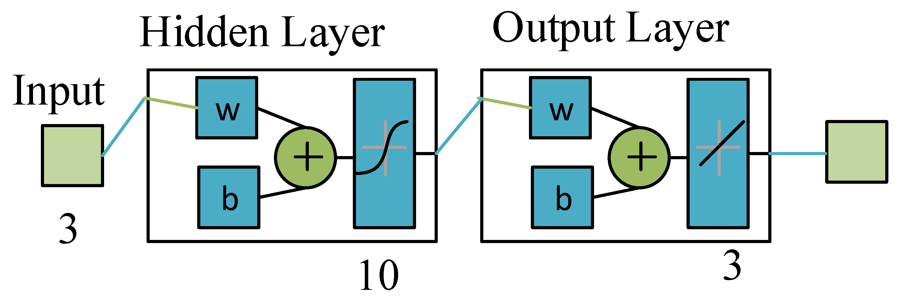
The best part of the proposed algorithm is that there is no need for mathematical modeling, and there is a self-computing tool for training the ANN controller. The model can be trained on the basis of input-output data of the system. The basic model of ANN structure is shown in Figure 6. The valuable feature of the ANN controller is the ability to learn, adapt, calculate the mean square error and predict the uncertainties required to reduce the error between input and output. Additionally, the ANN controller uses the same method for training the shunt, as well as the series compensator. For UPQC compensation the response of the controller needs to be rapid and accurate. In the ANN controller, the detection of a disturbed signal is fast and accurate, and processing of the reference signal is also high. The SRF controller is complex and less satisfactory under non-linear load disturbances, whereas the ANN based controller gives a fast dynamic response over a large operating range [17,18].
All the inputs to ANN are given to the input layer where they are stored in and processed to the hidden layer where multiplication is performed between weights of input and bias that is given to the hidden layer. After performing certain calculations, the results are processed to the output layer. The data in ANN is processed in parallel so it is fast as compared to other systems [17]. Different types of learning rules and architectures are within ANN for generation of reference current and voltages. For this paper, feed forward error back propagation is chosen as suitable for power electronic applications. In this architecture, if the output is not desired then it diagnosis the mean square error and send the weights to the back and front until the desired output is not achieved and error is not eliminated.
  • For creating and training the ANN model, the built-in command in MATLAB environment (nftool) is used, and its working is explained in Figure 7. Moreover the performance analyzed by looking at its mean square error and regression curve analysis.
  • The network automatically sets by default based on the number of samples, 70% of samples for training, 15% for validation and 15% for testing.
  • The size of the system can be selected according to the hidden layer selected for training the network. The number of neurons can be changed if the system does not perform well after training.
  • The training will be continued until the generalization stops improving and the number of iterations has completed its desired epochs. It can be stopped by evaluating the mean square error; if it is small enough, then the user can stop it.
  • After successful training the Simulink model can be created.

2.3.1. Balancing of DC-Link

For capacitor voltage balancing, real voltage is evaluated with reference voltage (700 V) and its equivalent error is considered as the input data and the estimated output (i.e., loss component of current (Idc) from ANN is taken as the target data to the network). For capacitor voltage balancing, reference voltage (700 V) is compared with actual voltage (Vdc) and its corresponding error is considered as the input data and the estimated output (i.e., loss component of current (Idc from ANN) is given as the target data to the network. There are 10 hidden layers and the network is trained using the Levenberg Marquardt backpropagation algorithm, which is quick and decreases mean square error by automatically adjusting input weights to remove MSE (mean square error). The ANN model for capacitor voltage balancing using MATLAB/Simulink is illustrated in Figure 8.

2.3.2. Shunt Controller Based on ANN

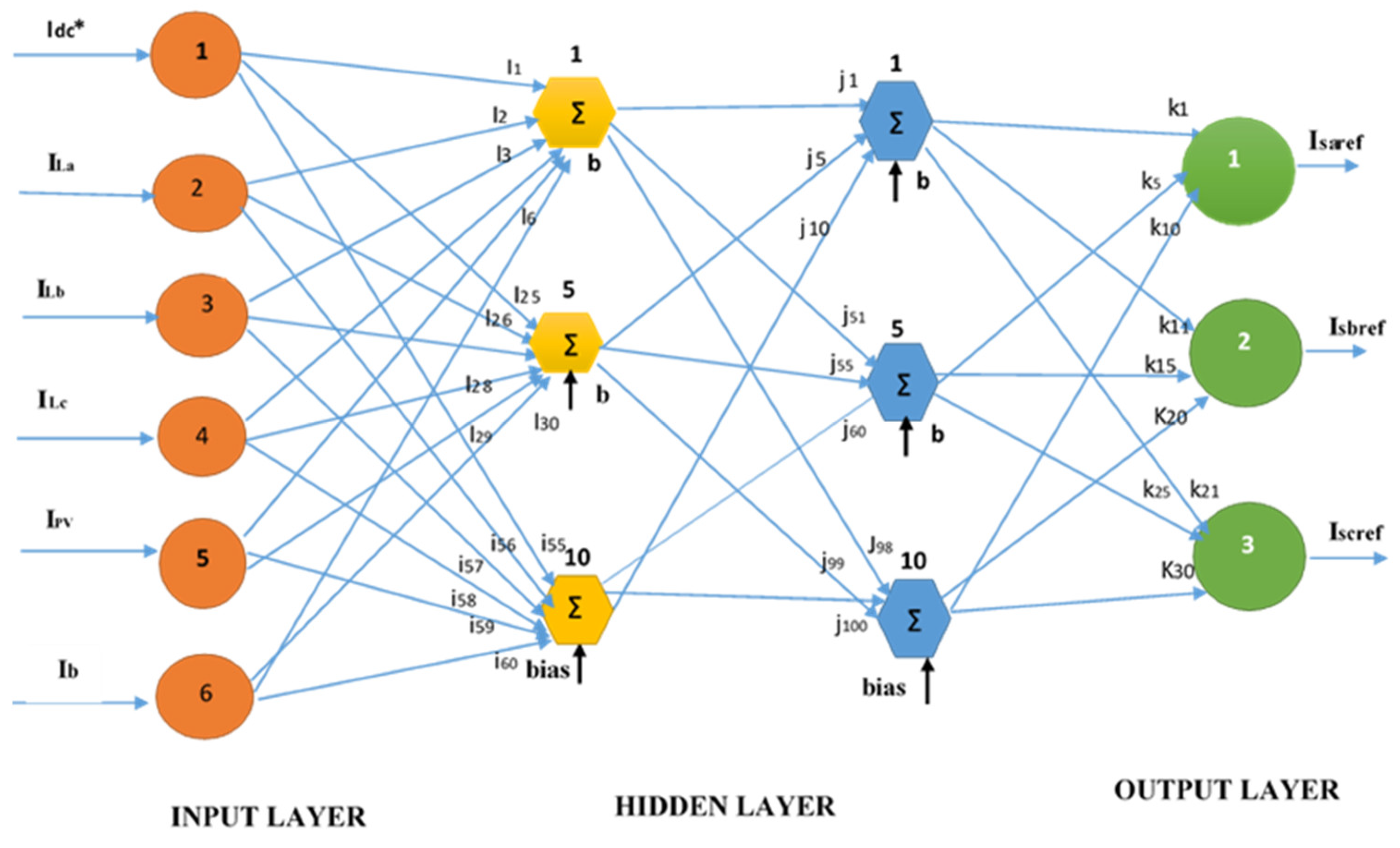
For generation of reference signals, load currents (ILa, ILb, ILc), Idc, IPV, and Ib have been taken as input signals and estimated currents are taken as output data for training the ANN shunt model by choosing the hidden layers. The Levenberg Marquard training algorithm has been selected for speed and least mean square error. Hence the reference current signals are generated which are compared with actual currents and passed through the hysteresis controller for the generating of pulses to switch on and off the IGBTs. The MATLAB simulated ANN model of the shunt compensator is illustrated in Figure 9. It is shown that the model has six inputs with 10 units of hidden layer, and three outputs are produced from the model.
The PV-battery-UPQC system is modelled in Figure 10 to represent the simulation structure of input and output data for the generation of reference signals in order to compensate the network. For this purpose, load current, dc loss current, PV current and battery current are sent to the processor for processing of the corresponding reference signals. The block diagram is represented in Figure 10.
There are multiple elements interconnected to form ANN as shown in Figure 11. The structure is similar to the human brain, performing together to create the reference signals with the selected number of neurons and weights of inputs [18]. There are six neurons taken as input, with 10 neurons in the hidden layers and three neurons of output layer. The architecture is not fixed, depending upon the problem to be solved. The number of input neurons is independent and the output neurons are dependent. Each neuron is connected to by links that carry information about weight from each input, then sums up to create a new weight value and passes this to the non-linear function. The most prominent feed-forward back-propagation architecture is used to map the input-output of ANN. The input signal generates through the network in a forward direction, from the layer of inputs to the hidden layers and then to the output neurons. In this paper, the network was simulated with six variables (load currents, PV current, battery current and loss current) as input and three variables (reference currents) as output. In the hidden layers, 10 neurons/units are chosen. The input variables (a = 1, …, 6), training hidden units (i = 1, …, 10, j = 1, …, 10) and output units are used as reference neurons. The product of the input values and weights of the connections between the input and hidden units are added. The overall input weight, A, is presented as
A i = a = 1 6 I i W i j
Wij is the weight between input and hidden layer, and Ai generates the activation level of hidden layer Hj. The hidden layer activity level is represented as:
H j = 1 1 + e a j
To predict the output value, the activity level of the hidden layer is multiplied by the weights of the output.
Y i = j = 1 3 H j W i j
Equation (6) represents the predicted value of output generated from the network. Thus, it is compared with the observed output and predicted output to calculate the mean square error.
R M S E = 1 N [ O Y ]
Here N represents the sample size. Each unit weight is set by using a back-propagation learning function to reduce the mismatch between the observed and predicted outputs until the least RMSE is achieved.

2.3.3. Series Controller Based on ANN

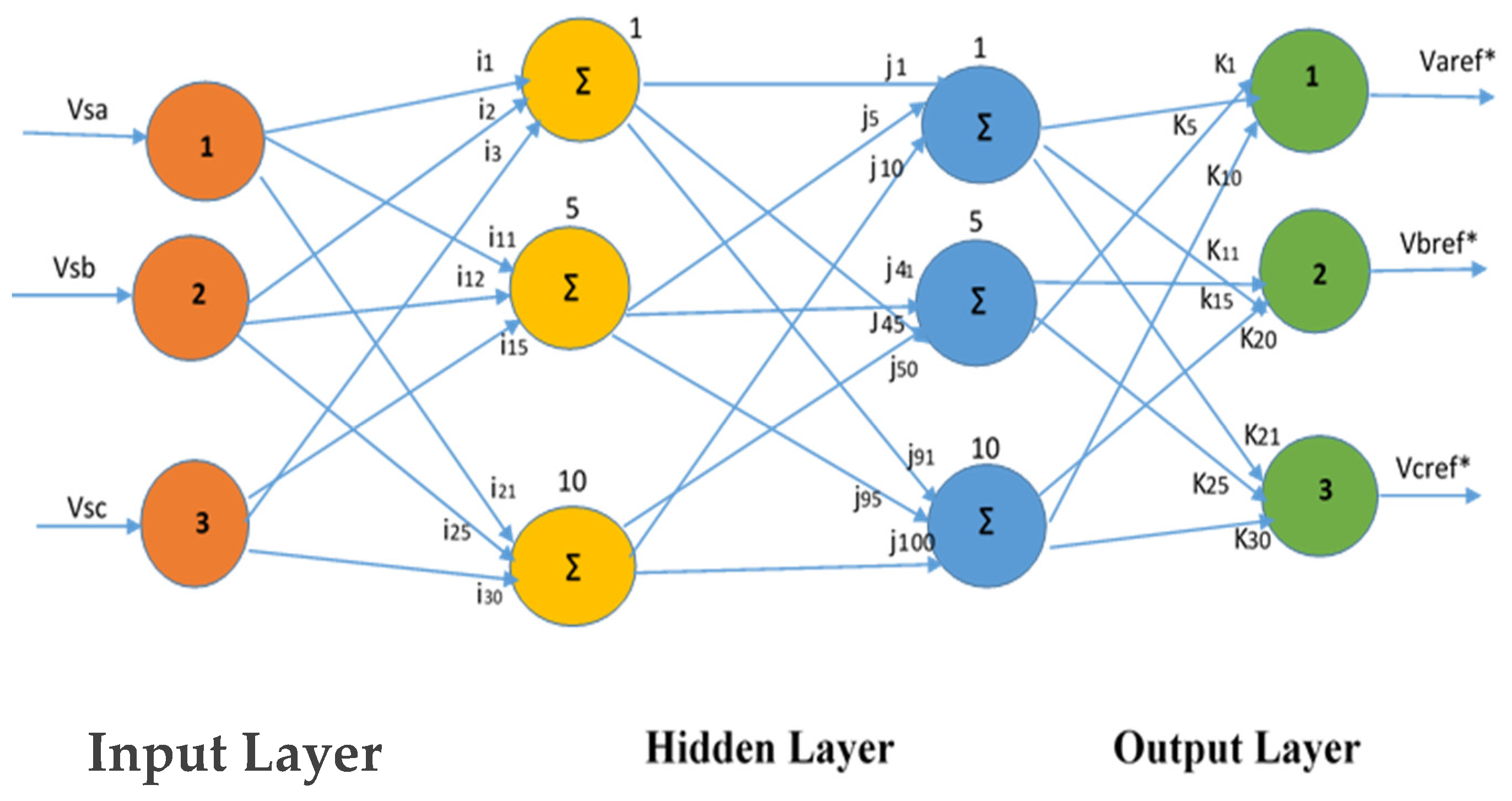
The series compensator is the part of the UPQC which is used for mitigation of voltage related problems such as, voltage flickers, sag/swell and harmonics in voltages [17]. In this compensator, reference voltages are generated for injection of voltages to the network. To produce voltage reference signals by the ANN control scheme, supply voltages (VSa, VSb and VSc) are taken as input data and the estimated reference currents are taken as targeted data. The number of hidden layers is 10 and a Levenberg-Marquardt backpropagation algorithm s used to train the ANN network, then these reference signals are compared with distorted supply and passed to the PWM controller for operation of the IGBTS. The MATLAB ANN model of series compensator is illustrated in Figure 12 and it is seen that the model has three inputs with 10 units of hidden layer, and three outputs are produced from the model.
The PV-battery-ANNIS system series is modelled in Figure 13 to represent the simulation structure of input and output data for reference voltage signals generation to compensate for the voltages. For this purpose, distorted supply voltages are given to the processor for processing of the corresponding reference signal voltages. The block diagram is represented in Figure 13.
There are three neurons taken as input with 10 neurons in the hidden layers and three neurons in the output layer as shown in Figure 14. In the series compensator, the network is simulated with three variables (supply voltages) as input and three variables (reference currents) as output. In the hidden layers, 10 neurons/units are chosen for fast response, with input variables (a = 1, 2, 3), training hidden units (i = 1, …10, j = 1, …10) and output units as (k = 1, 2, 3). The product of the input values and weights of the connections between the input and hidden units are added. The overall process is as discussed for the shunt compensator.

3. Designing and Configuration of System

For designing the power quality controller, some parameters need to be selected and are represented in Table 1.
The structure of the PV-Battery-UPQC system is shown in Figure 15. The system is designed as a three phase system. The PV-Battery-UPQC consists of a shunt active power filter and a series active power filter connected back-to-back with a common DC-bus. The system is designed such that the shunt APF is connected with the load side and the series APF is connected with the source side, whereas the PV and battery are connected directly to UPQC with DC-link. The series APF is operated in voltage controlling mode for mitigation of voltage related problems such as sag/swell and shunt. APF is operated in current control mode for the mitigation of current related problems such as harmonics and unbalancing. The shunt and series are connected to the grid by interfacing inductors. The series injected transformer is connected for injecting of the compensated voltage required for the mitigation voltage problem in the grid. A non-linear load is used which consists of a bridge rectifier.

3.1. Design of PV & Battery

For best performance of the system, proper sizing of the PV array, dc-voltage level and dc-link capacitor is selected carefully. The sizing of the shunt compensator is carried out so it can take output from the PV array, apart from compensation for the reactive power and harmonics to the load current. As the PV array is directly connected to the dc-link capacitor, the PV array is designed with the help of a MPPT algorithm, as it delivers the same voltage as the dc-link voltage. In normal conditions, the PV array delivers active power to the load and feeds power to the grid.

3.1.1. dc-Link Voltage Magnitude

Vdc depends upon the modulation depth used and the system’s per phase voltage. The system dc-link voltage must be double the per phase peak voltage of the system, and computed as:
V d c = 2 2 V L L 3 m
Here modulation depth is m which is taken as 1 and VLL is line voltage of grid. For line voltage the dc voltage is calculated as 660 V, which is approximately 700 Vdc,5. This is the same as the PV array delivers for the voltage after MPPT algorithm at standard temperature condition.

3.1.2. Selection of Cdc

This is designed on requirement of the power, as well as voltage of dc-bus. The energy equation of the dc capacitor is given as below:
C d c = 3 k δ V p h I p s h t 0.5 × ( V D C 2 2 V D C 1 2 )
Here k is dynamic energy change, δ is overloading factor, Vdc2 is average voltage of dc us, Vdc1 = 670 as found from Equation (1), the smallest required value of dc-bus voltage, Vph is per phase voltage, t is the required time for obtaining steady value after disturbance, Ipsh is per-phase current of shunt compensator, and k is variation of energy in dynamics. The smallest required dc-bus voltage = 670 V, Vdc2 = 700 V, k = 10%, Vph = 300 V, Ish = 34 A, t = 30, δ = 1.5 so the value of Cdc is as follows:
C d c = 3 × 0.1 × 1.5 × 300 × 34 × 0.03 0.5 × ( 700 2 670 2 )
C d c = 6.6 m f

3.1.3. Shunt Compensator Interfacing Inductor

This is based on ripple current, dc-link voltage and switching frequency. It is expressed as:
L s = 3 × m × V D C 2 12 × k × f s × I r p p
L s = 3 × 1 × 700 12 × 1.5 × 10,000 × 6.9 = 1   mH
Here m = modulation depth, k = overloading factor, fs = switching frequency, Ir,pp = ripple current of inductor, which is 20% rms phase current.

3.1.4. Injection Transformer

As the requirement of system is designing sag/swell conditions at a specific value which is considered as 0.3 p-u for the system, if the dc-bus generates 700 voltages it will lead to approximately 80 V reduction in voltage magnitude when sag occurs; however, in case of swell the magnitude will increase with the addition of 80 V in total magnitude. When the average dc-bus voltage gives 700 V, it will go to the lower or upper modulation index. In case of operation of series compensator, voltage harmonics must be eliminated and modulation index must be kept at unity. For this purpose, the series transformer is added with a certain turn ratio:
T s e = 3 × V S I × I S C = 3 × 72 × 42 = 10   kVA
Here VSI is sag condition voltage and Isc is current during swell, which is 42 A. Therefore series injection transformer VA rating is selected as 10 KVA.

4. Results and Discussions

The performance of both compared techniques is discussed and the parameters of PV are taken as standard condition of temperature and irradiation (1000 W/m2, 25 °C). The system is judged on the basis of balanced and unbalanced non-linear conditions. The results are presented below and THD is also shown.

4.1. At Load Unbalanced Conditions

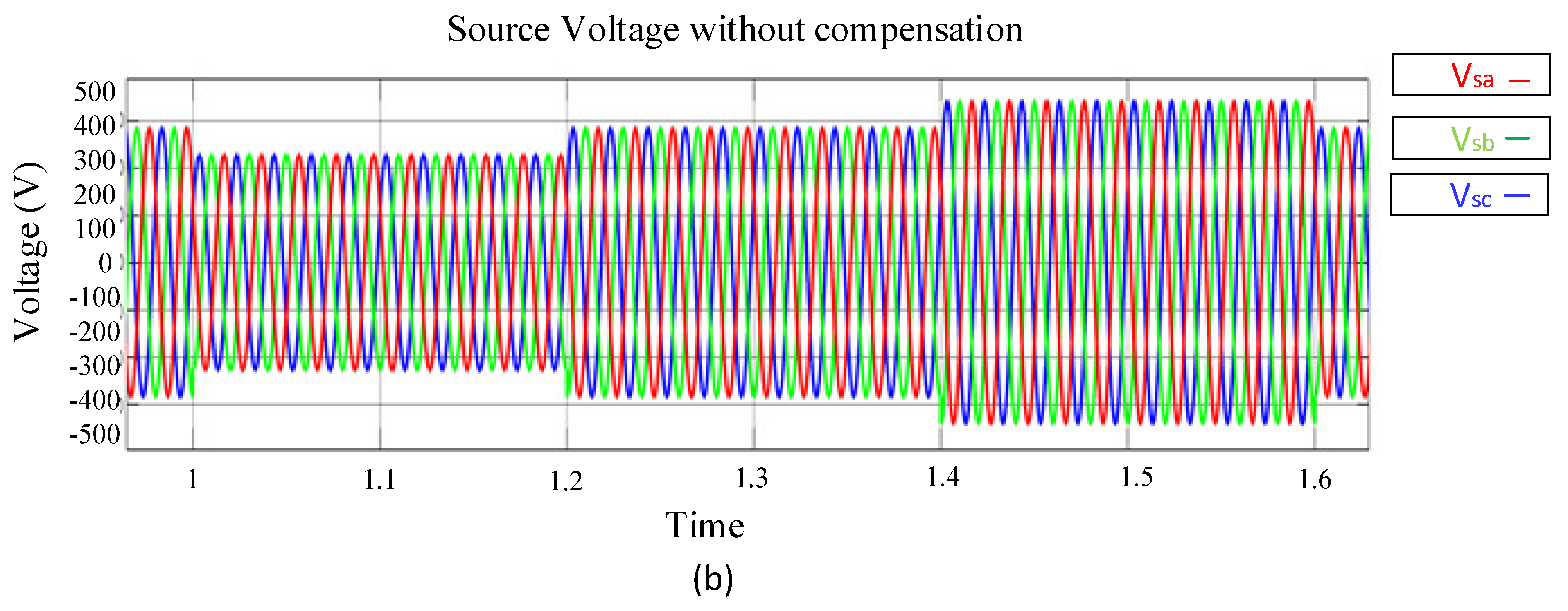
The parameters of the system fluctuate when operating with non-linear loads. These non-linear loads draw currents in the form of abrupt short pulses, as shown in Figure 16a, from t = 0.45 to t = 0.5 and 0.7 to 0.75, etc. The current waveforms are distorted by these pulses, which create harmonics that can result in influencing the load connected to it and the equipment of the distribution system. Moreover, there is a phase unbalancing depicted in Figure 16a which is due to a mismatch of supply voltage that can result in damage to costly equipment. In addition to this, Figure 16b shows the supply voltage scenario of voltage sag and swell. The voltage sag is defined as a 10% or more fall in RMS voltage value below typical or recommended usage. Voltage swell, on the other hand, is defined as an increase in RMS voltage of 10% or more over typical or recommended usage. In Figure 16b, both voltage sag and swell have occurred up to a 30% reduction and increment in voltage level, which needs to be compensated for by the UPQC device. The swell and sag in supply voltages can be noticed in Figure 16b.

4.2. At Unbalanced Mitigation

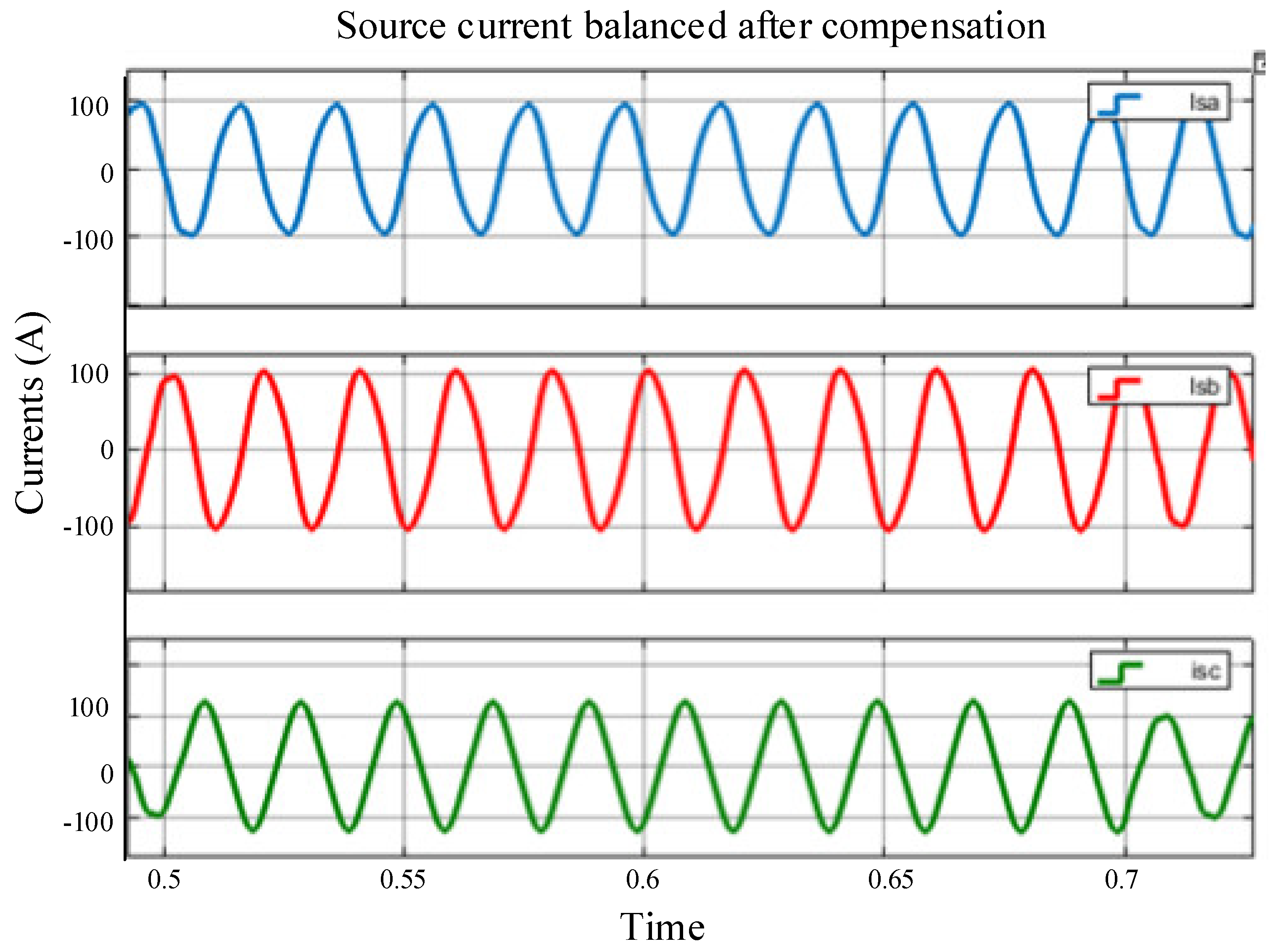
It can be noticed in Figure 16a that phase C has become zero from t = 0.5 s to t = 0.7 s due to a mismatch in supply voltage. This causes an abnormality in overall system operation. In order to mitigate the phase unbalancing and achieve smoother operation, the UPQC compensation has been implemented based on SRF and ANN control techniques. In Figure 17, the result has been depicted using both techniques, which shows that phase C has become sinusoidal. Both SRF and ANN techniques mitigate the phase unbalancing successfully, but the SRF controller is slower as compared to ANN. Figure 17 is depicted to represent the mitigation after UPQC compensation.

4.3. At Sag Condition

The performance of the PV-battery based UPQC with the proposed ANN control technique is tested with a distorted voltage supply of 30% of voltage sag. The sag duration period, from t = 1 s to t = 1.2 s, is depicted in Figure 18a. The supply voltages decrease from 415 V to 280 V. In Figure 18b, it is noticed that the ANN converter efficiently decreases for the voltage sag required and sustains the sinusoidal voltage waveform required for continuous and smoother power supply. All this occurs with the help of a UPQC based ANN device. Here it is to be noticed from Figure 18d that the proposed UPQC technique effectively mitigates the harmonics; it shows the smoother and sinusoidal results for source current and load voltage.

4.4. At Swell Condition

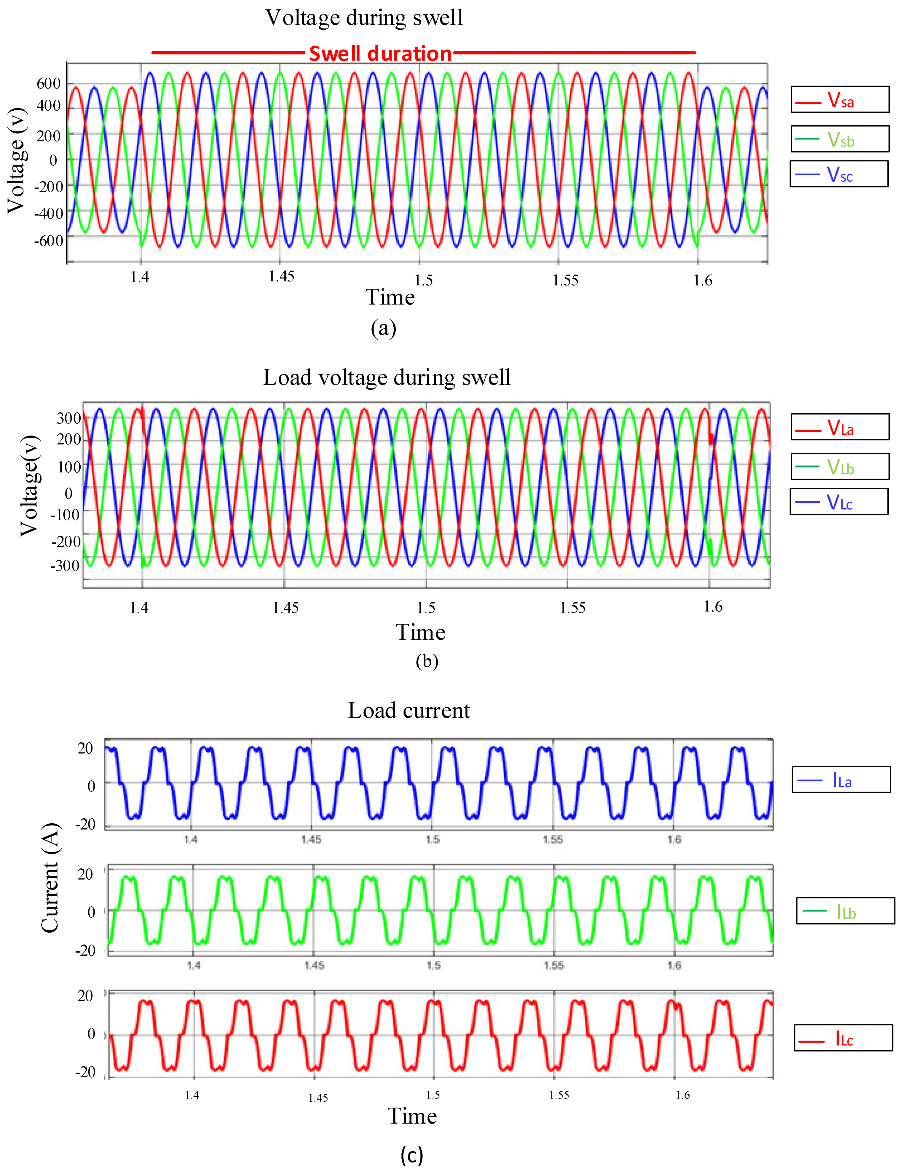
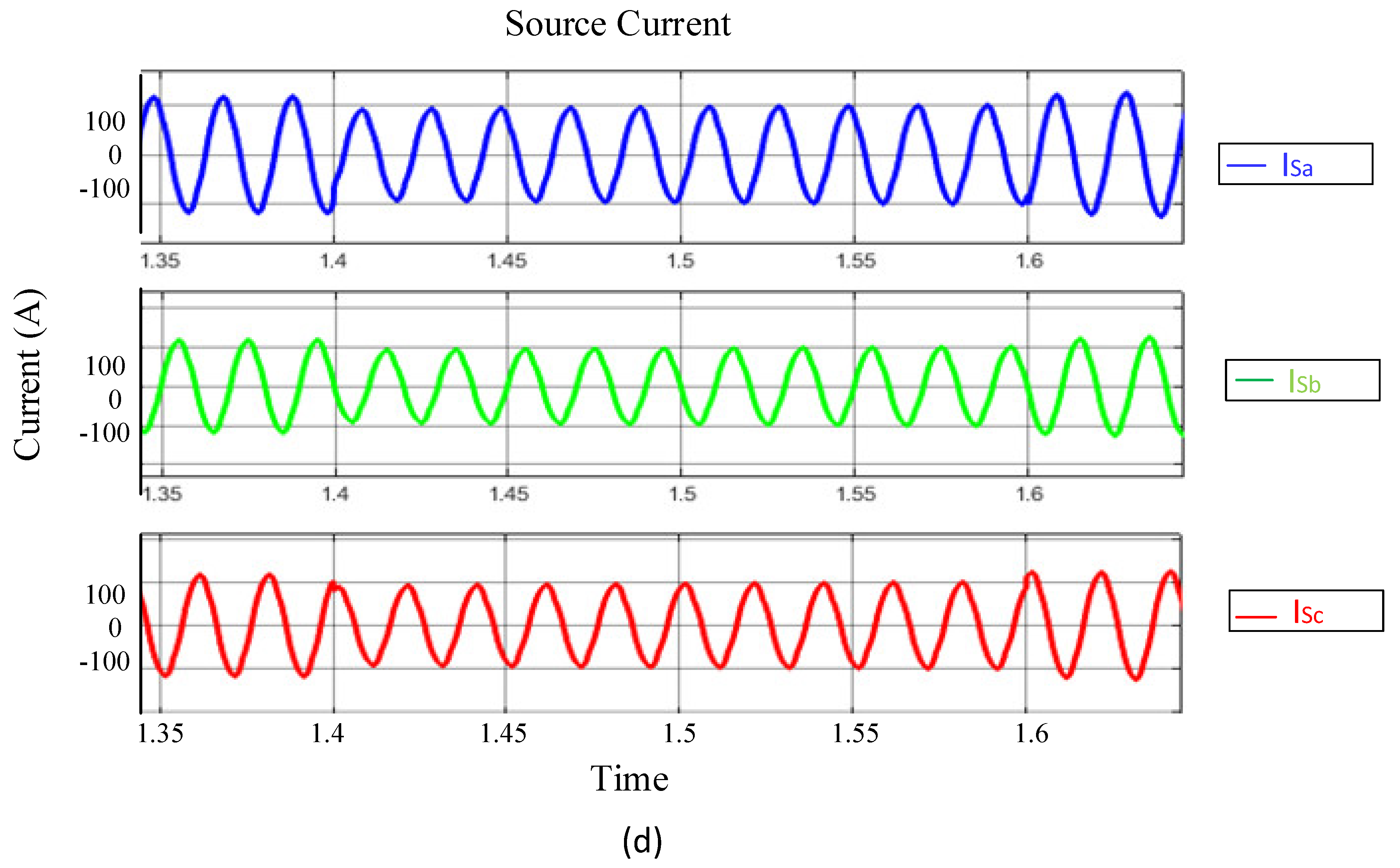
In this case, the performance of the PV-battery-UPQC with proposed ANN control technique is analyzed with a distorted voltage supply and with 30% of voltage swell. The swell duration period, from t = 1.4 s to t = 1.6 s, is depicted in Figure 19a. The supply voltage increase from 415 V to 615 V. In this case, the series converter occupies and avoids the risen voltage with the help of the dc-link capacitor. In Figure 19b, it is noticed that ANN-based UPQC efficiently compensates for the amplified voltage swell required for compensation and sustains the sinusoidal voltage waveform. This scenario causes the shunt converter to decrease the number of currents drawn from the line that is used for reactive power compensation in the supply. This is noted in Figure 19d.

4.5. Injected Voltage of Series Converter

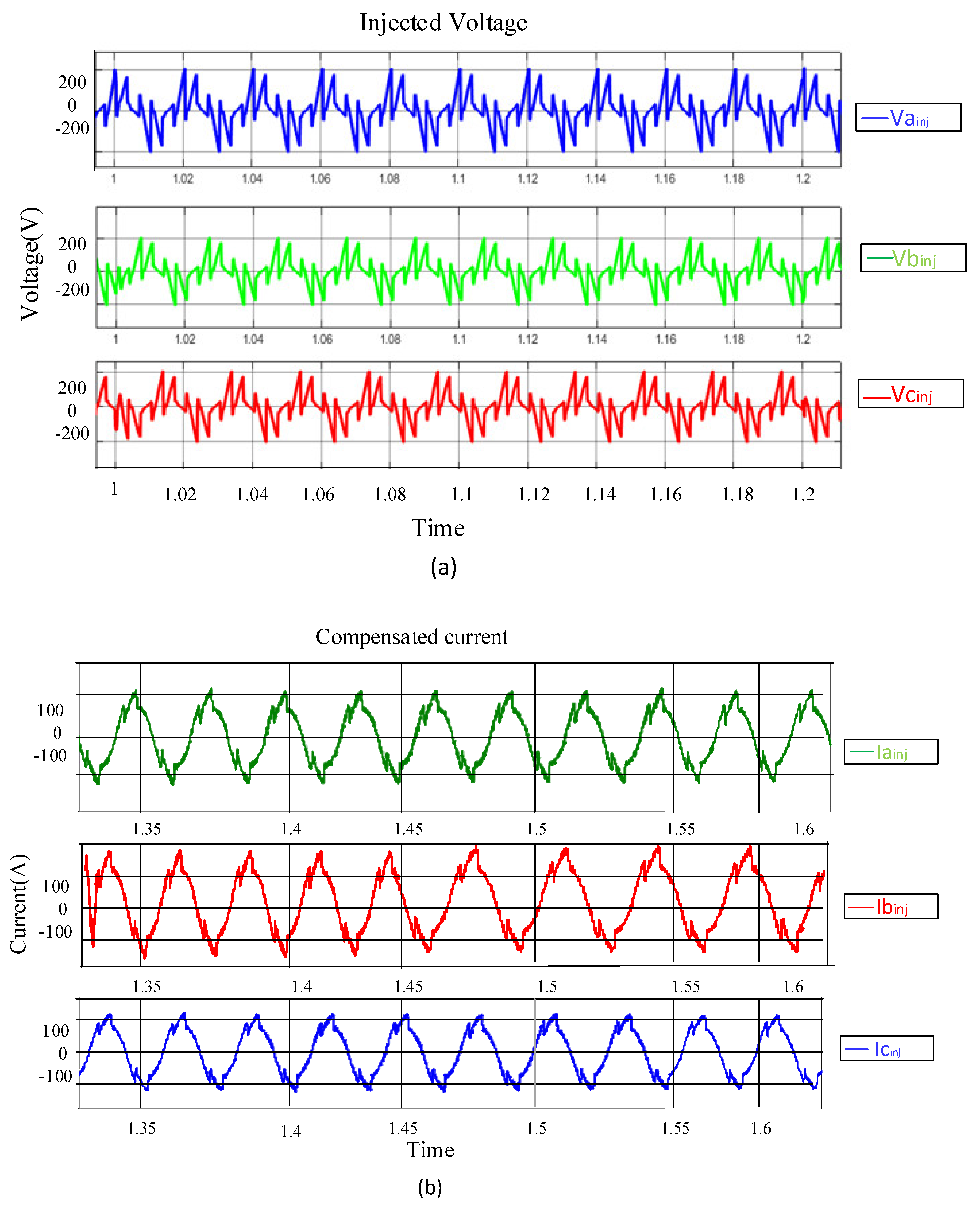
It is noticed that the ANN based series converter gives or takes the voltage from the line during the sag and swell condition occurred in supply voltage to maintain the load voltage sinusoidal, along with mitigating the harmonics of the load side. It is also noted from Figure 20a that the magnitude feed by the series converter is dependent upon the magnitude of distorted voltage from the component of its fundamental. The voltage injected by the series converter during the sag is shown in Figure 20a.

4.6. Injected Current of Shunt Converter

The ANN based shunt converter supplies the current in a phase opposite to the harmonics present in load currents produced by unbalanced and non-linear loads; therefore, supply currents must be compensated. It is noted that the magnitude of current fed by the shunt converter is dependent upon the magnitude of distorted current from the component of its fundamental. The shunt converter fed the reactive currents for supply current compensation, illustrated in Figure 20b.

4.7. Voltage Balancing of Capacitor

Maintaining the constant dc-link is the most important aspect of UPQC. ANN and SRF control techniques are investigated and compared in this paper for balancing of the dc-link voltage along with the generation of reference current and voltage signals. Comparison between the ANN and SRF dc-link voltage has been shown prominently in Figure 21. Dc-link voltage-based SRF controller is shown in Figure 21a. It is noticed that there is a high overshoot, approx. t = 1.15 volts to achieve its steady-state, and a very high amount of fluctuation and variations are present in the response of the SRF based controller. On the other hand, an ANN controller has a faster rise time. It gains its final output in just t = 0.09 s with a lower delay time, no overshoot, and no visible fluctuation. In ANN, capacitor voltage reaches its steady-state faster than compared SRF. In the SRF technique, it is also noticed that during the sag and swell compensation, the magnitude of dc-link voltage varies with a high number of variations. From this, it is clear that the proposed ANN controller works efficiently.

4.8. Total Harmonic Distortion

In Table 2, THD is represented based on SRF and ANN controller techniques. It is noticed that in both techniques, the THD level has decreased and been brought down. The ANN controller has efficiently reduced the high amount of THD in comparison to SRF in both current and voltage parameters. Moreover, the dynamic comparison of both control techniques is presented in Table 3.
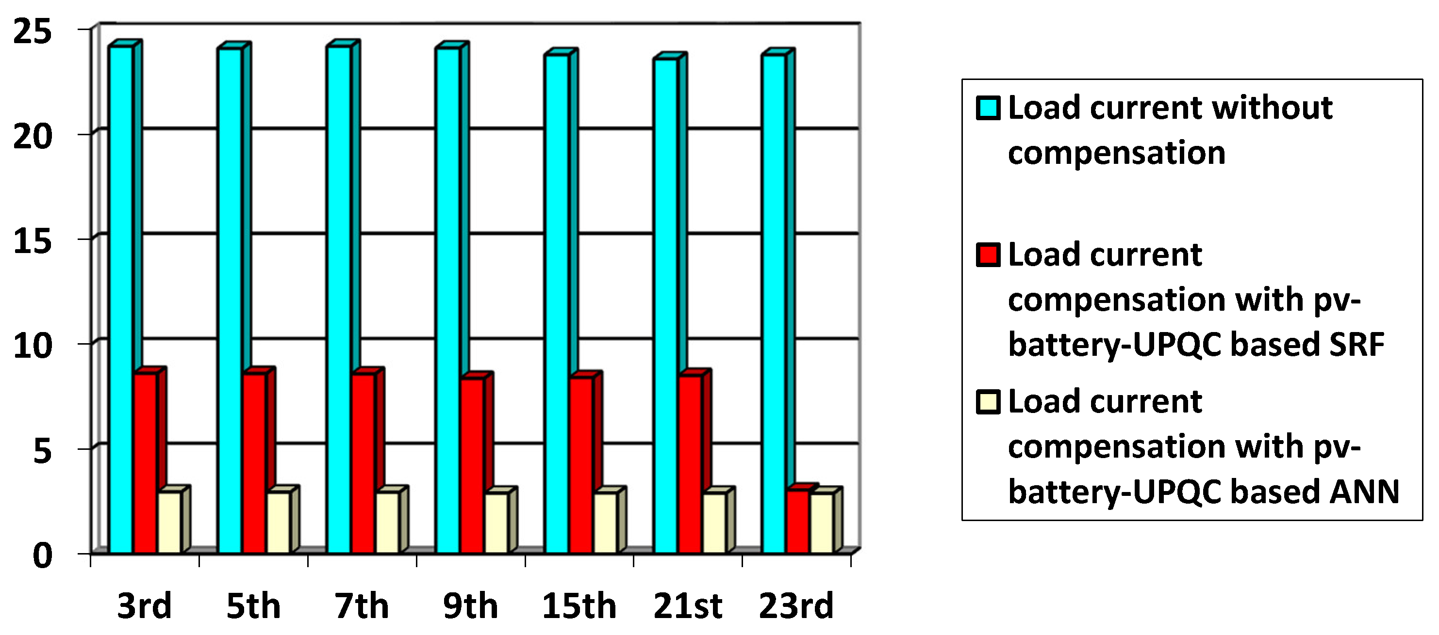
The ANN and SRF controllers in the PV-battery-UPQC system have reduced the percentage of THD value of the load current. The percentage of THD achieved in SRF for 3rd, 5th, and 7th order harmonics is 8.64%, 8.64%, and 8.48%, respectively, whereas the percentage achieved in ANN for 3rd, 5th and 7th order harmonics is 2.64%, 2.64%, and 2.48% respectively, which are under the limit as per IEEE-519 standards. The PV-battery-UPQC system was also investigated for higher-order harmonics on 15th, 21st, and 23rd. The values are depicted in Figure 22. As the percentage of THD decreases, the load current waveform is more sinusoidal, and the power quality is improved. The ANN controller performed effectively well in reducing the THD value of the load current when compared with a conventional SRF controller as the average harmonic reduction for the above-specified harmonics has been increased by a 24.1%. The performance improvement is evident in Figure 22.
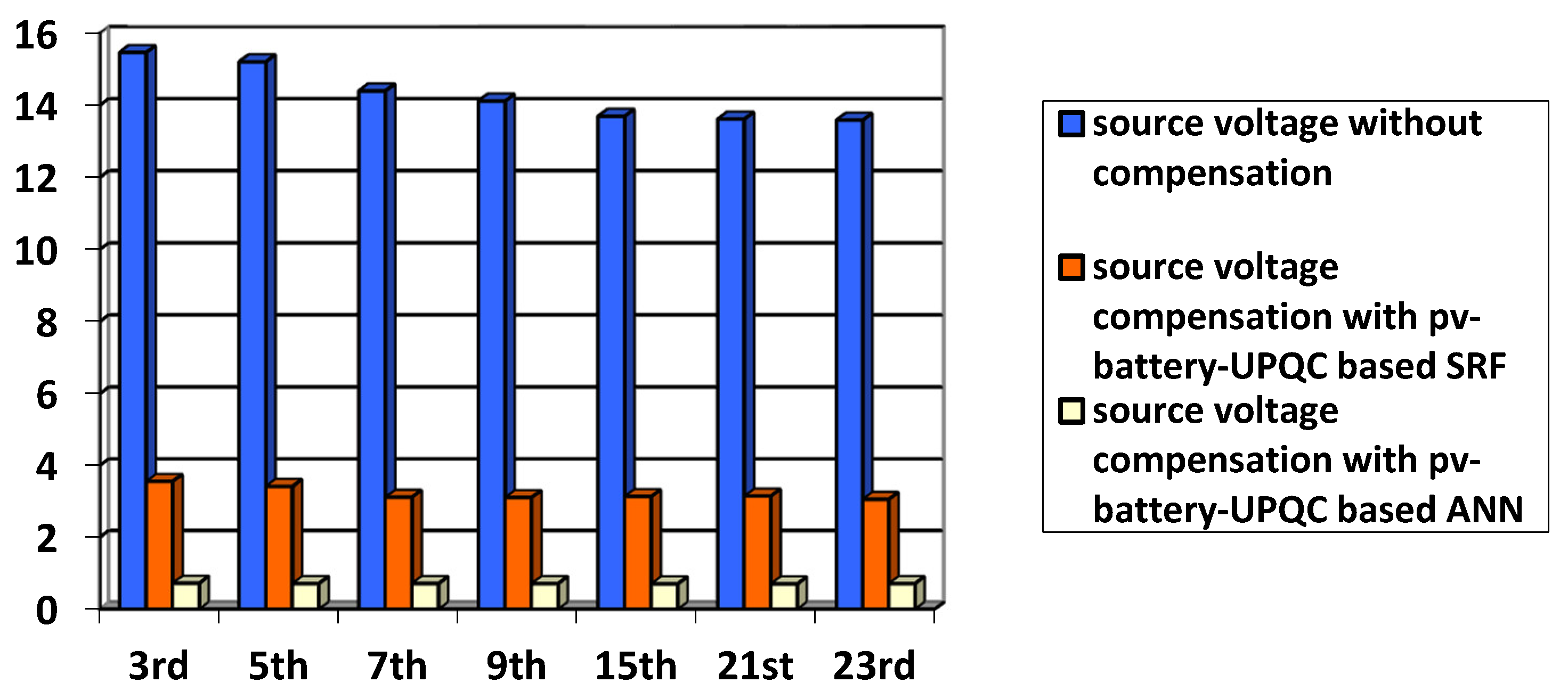
The proposed ANN over SRF controller in the PV-battery-UPQC system has also reduced the percentage of THD value of source voltage. The percentage of THD achieved in SRF for 3rd, 5th and 7th order harmonics are 3.54%, 3.64%, and 3.48%, respectively, whereas the percentage achieved in ANN for 3rd, 5th, and 7th order harmonics is 0.72%, 0.71%, and 0.71%, respectively, which are under the limit as per IEEE-519 standards. The PV-battery-UPQC system was also investigated for higher-order harmonics on the 15th, 21st, and 23rd. The values are depicted in Figure 23. As the percentage of THD decreases, power quality is improved. The ANN controller also performed effectively well in reducing the THD value of the source voltage when compared with a conventional SRF controller.

5. Conclusions

The performance of the proposed PV-battery-UPQC based ANN controller is tested with distorted supply voltage, non-linear, unbalanced loads, and penetration of renewable energy system. It is noted that the PV-battery-based UPQC with ANN successfully compensates for harmonics in load voltage and source currents and successfully mitigates voltage sag and swell. With the incorporation of the advanced control of the ANN technique, the response of the capacitor is faster, and it compensates for the current unbalancing and harmonic mitigation accurately. It is also noticed from the results that the proposed technique has also decreased THD levels much more effectively as compared to a SRF based control scheme. The proposed ANN technique has also eliminated the mathematical operations. So, the DSPs and FPGAs are not required for the implementation of the control scheme, which decreases the cost as well as the complexity of the system. The proposed control scheme requires a low-size memory to be implemented in the microcontroller. Besides this, PV-battery integrated UPQC improves the power quality and supplies power to the grid and load connected when needed. It has been proved that ANN has better results than SRF. The performance of this system is simulated in MATLAB/Simulink. The ANN control scheme provides better control, eliminates current harmonics, decreases the voltage fluctuation, reduces the %THD level according to IEEE standards, and improves the power quality. The improvement in all these parameters found the ANN controller superior as compared to SRF. From the results, it has been shown that the proposed controller has an awesome steady-state and transient response in dynamic conditions. Moreover, the high cost of the conventional scheme has also been eliminated by using this intelligent approach. This system can be further tested and implemented in a real-time prototype.

Author Contributions

Data curation, H.M.; Formal analysis, M.F.E.; Methodology, H.M.M.; Resources, J.B.S.; Software, F.A. and R.H.; Supervision, S.K.; Writing—review & editing, J.M.G. All authors have read and agreed to the published version of the manuscript.

Funding

This research received no external funding.

Institutional Review Board Statement

Not applicable.

Informed Consent Statement

Not applicable.

Data Availability Statement

Not applicable.

Conflicts of Interest

The authors declare no conflict of interest.

Nomenclature

APFActive power filter
ANFISAdaptive neuro fuzzy inference
MGMicro grid system
MGUUtility connected micro grid system
PQPower Quality
ANNArtificial neural network
ANNMPCArtificial Neural Model predictive control
PCCPoint of common coupling
UPQCUnified power quality conditioner
VSIVoltage source inverter
SRFSynch nous reference frame
THDTotal harmonic distortion
MPPTMaximum power point tracking
HPFHigh pass filter
LPFLow Pass Filter
MAFMoving average filter
VocOpen circuit voltage
ISCShort circuit current
VSabcSupply Voltages
IPVgPV Current
PVPhotovoltaic Array
PPVPhotovoltaic Power
IbBattery Current
IdcDc Current
PWMPulse Width Modulation
VDCDc link Voltage
VrefReference Voltage
PIProportional Integral
LVRTLow voltage ride through
SWTsynch squeezing wavelet transform
FACTSFlexible AC transmission system
CPDCustom power device
DVRDistorted Voltage Regulator
APCActive Power Conditioner
AVCActive Voltage Conditioner
PLLPhase Locked Loop
DSTATCOMDistribution Static Synch nous Compensator
IARInstantaneous Active-Reactive
FFTFast Fourier Transform
UVTUnit Vector Template
DWTDiscreet Wavelet Transform
ECAExponential Composition Algorithm

References

  1. Devassy, S.; Singh, B. Design and Performance Analysis of Three-Phase Solar PV Integrated UPQC. IEEE Trans. Ind. Appl. 2018, 54, 73–81. [Google Scholar] [CrossRef]
  2. Devi, S.C.; Chandrakala, S.; Shah, P.; Devassy, S.; Singh, B. Solar PV array integrated UPQC for power quality improvement based on modified GI. In Proceedings of the 2020 IEEE 9th Power India International Conference (PIICON), Sonepat, India, 28 February–1 March 2020; pp. 1–6. [Google Scholar]
  3. Kinhal, V.G.; Agarwal, P.; Gupta, H.O.; Member, S. Performance Investigation of Neural-Network-Based Unified Power-Quality Conditioner. IEEE Trans. Power Deliv. 2011, 26, 431–437. [Google Scholar] [CrossRef]
  4. Kaushal, J.; Basak, P. Power quality control based on voltage sag/swell, unbalancing, frequency, THD and power factor using artificial neural network in PV integrated AC microgrid. Sustain. Energy Grids Netw. 2020, 23, 100365. [Google Scholar] [CrossRef]
  5. Gupta, N.; Seethalekshmi, K. Artificial neural network and synchrosqueezing wavelet transform based control of power quality events in distributed system integrated with distributed generation sources. Int. Trans. Electr. Energy Syst. 2021, 31, e12824. [Google Scholar] [CrossRef]
  6. Kumar, A.S.; Rajasekar, S.; Raj, P.A.-D.-V. Power Quality Profile Enhancement of Utility Connected Microgrid System Using ANFIS-UPQC. Procedia Technol. 2015, 21, 112–119. [Google Scholar] [CrossRef] [Green Version]
  7. Khadkikar, V. Enhancing electric power quality using UPQC: A comprehensive overview. IEEE Trans. Power Electron. 2012, 27, 2284–2297. [Google Scholar] [CrossRef]
  8. Han, B.; Bae, B.; Kim, H.; Baek, S. Combined operation of unified power-quality conditioner with distributed generation. IEEE Trans. Power Deliv. 2006, 21, 330–338. [Google Scholar] [CrossRef]
  9. Kesler, M.; Ozdemir, E. Synchronous-reference-frame-based control method for UPQC under unbalanced and distorted load conditions. IEEE Trans. Ind. Electron. 2011, 58, 3967–3975. [Google Scholar] [CrossRef]
  10. Lu, Y.; Xiao, G.; Wang, X.; Blaabjerg, F.; Lu, D. Control strategy for single-phase transformerless three-leg unified power quality conditioner based on space vector modulation. IEEE Trans. Power Electron. 2016, 31, 2840–2849. [Google Scholar] [CrossRef]
  11. Shukla, S.; Mishra, S.; Singh, B.; Kumar, S. Implementation of empirical mode decomposition based algorithm for shunt active filter. IEEE Trans. Ind. Appl. 2017, 53, 2392–2400. [Google Scholar] [CrossRef]
  12. Rahmani, B.; Li, W.; Liu, G. A wavelet-based unified power quality conditioner to eliminate wind turbine non-ideality consequences on grid-connected photovoltaic systems. Energies 2016, 9, 390. [Google Scholar] [CrossRef] [Green Version]
  13. Sindhu, S.; Sindhu, M.R.; Nambiar, T.N.P. An Exponential Composition Algorithm Based UPQC for Power Quality Enhancement. Procedia Technol. 2015, 21, 415–422. [Google Scholar] [CrossRef] [Green Version]
  14. Rao, R.V.D.R.; Pragaspathy, S. Enhancement of electric power quality using UPQC with adaptive neural network model predictive control. In Proceedings of the 2022 International Conference on Electronics and Renewable Systems (ICEARS), Tuticorin, India, 16–18 March 2022; pp. 233–238. [Google Scholar]
  15. Dheeban, S.S.; Selvan, N.B.M. ANFIS-based Power Quality Improvement by Photovoltaic Integrated UPQC at Distribution System. IETE J. Res. 2021, 1–19. [Google Scholar] [CrossRef]
  16. Aryanezhad, M.; Ostadaghaee, E. Robustness of unified power quality conditioner by neural network based on admittance estimation. Appl. Soft Comput. 2021, 107, 107420. [Google Scholar] [CrossRef]
  17. Vinnakoti, S.; Kota, V.R. Implementation of artificial neural network based controller for a five-level converter based UPQC. Alex. Eng. J. 2018, 57, 1475–1488. [Google Scholar] [CrossRef]
  18. Vinnakoti, S.; Kota, V.R. ANN based control scheme for a three-level converter based unified power quality conditioner. J. Electr. Syst. Inf. Technol. 2018, 5, 526–541. [Google Scholar] [CrossRef]
  19. Devassy, S.; Singh, B. Performance Analysis of Solar PV Array and Battery Integrated Unified Power Quality Conditioner for Microgrid Systems. IEEE Trans. Ind. Electron. 2021, 68, 4027–4035. [Google Scholar] [CrossRef]
  20. Kumar, R.; Bansal, H.O. Real-time implementation of adaptive PV-integrated SAPF to enhance power quality. Int. Trans. Electr. Energy Syst. 2019, 29, e12004. [Google Scholar] [CrossRef]
  21. Selmi, T.; Abdul-niby, M. P&O MPPT Implementation Using MATLAB/Simulink. In Proceedings of the 2014 Ninth International Conference on Ecological Vehicles and Renewable Energies (EVER), Monte-Carlo, Monaco, 25–27 March 2014; pp. 1–4. [Google Scholar]
  22. Kumar, A.; Mishra, V.M.; Ranjan, R. Low voltage ride through capability and power quality improvement in grid connected PV system using ANN tuned UPQC. In Proceedings of the 2021 IEEE 4th International Conference on Computing, Power and Communication Technologies (GUCON), Kuala Lumpur, Malaysia, 24–26 September 2021; pp. 1–6. [Google Scholar]
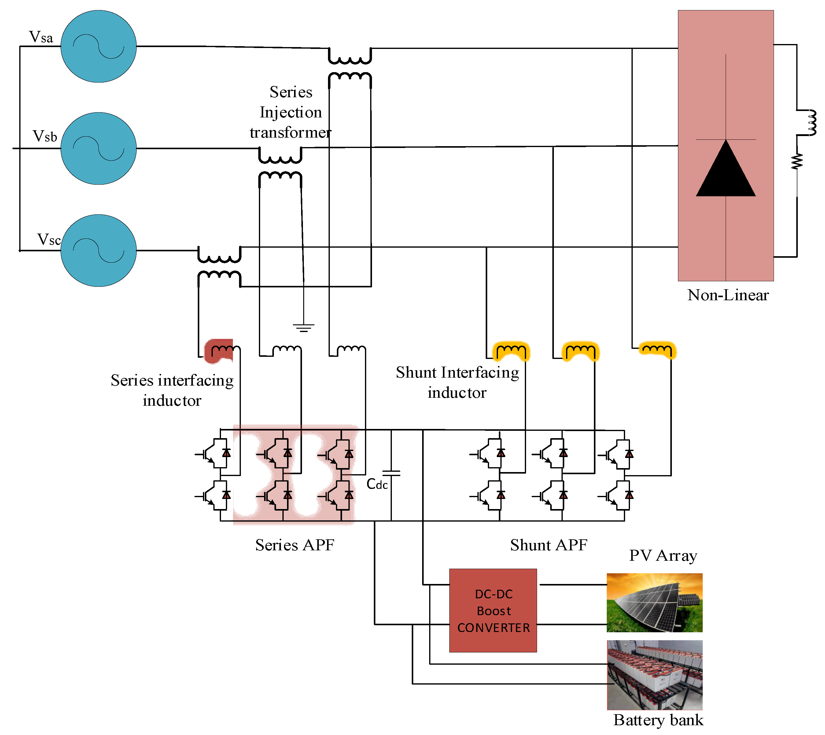
Figure 1. Block diagram of a system.
Mathematics 10 01989 g001
Figure 2. Maximum Power Point tracking algorithm.
Mathematics 10 01989 g002
Figure 3. PV array current and voltage with different conditions of irradiation.
Mathematics 10 01989 g003
Figure 4. Conventional control strategy of PV-battery-shunt active power filter.
Mathematics 10 01989 g004
Figure 5. Conventional control strategy of series active power filter.
Mathematics 10 01989 g005
Figure 6. ANN structure.
Mathematics 10 01989 g006
Figure 7. ANN training Algorithm.
Mathematics 10 01989 g007
Figure 8. Capacitor Balancing ANN Structure.
Mathematics 10 01989 g008
Figure 9. Shunt ANN Model.
Mathematics 10 01989 g009
Figure 10. Block diagram of Shunt ANN model.
Mathematics 10 01989 g010
Figure 11. Shunt ANN model development.
Mathematics 10 01989 g011
Figure 12. Series neural network.
Mathematics 10 01989 g012
Figure 13. Block diagram of Series ANN model.
Mathematics 10 01989 g013
Figure 14. Architecture of ANN series.
Mathematics 10 01989 g014
Figure 15. MATLAB Simulink Diagram.
Mathematics 10 01989 g015
Figure 16. (a) Load current before compensation, (b) source voltage without compensation.
Mathematics 10 01989 g016aMathematics 10 01989 g016b
Figure 17. Load unbalanced mitigation after UPQC compensation.
Mathematics 10 01989 g017
Figure 18. (a) supply voltages, (b) load voltages, (c) load currents, (d) source currents after UPQC compensation.
Mathematics 10 01989 g018aMathematics 10 01989 g018b
Figure 19. (a) Supply voltages (b) load voltages (c) load currents, before UPQC compensation (d) source currents, after UPQC compensation.
Mathematics 10 01989 g019aMathematics 10 01989 g019b
Figure 20. (a) Injected voltage (b) Compensated current.
Mathematics 10 01989 g020
Figure 21. (a) SRF based DC link capacitor voltage, (b) ANN based DC link Capacitor voltage.
Mathematics 10 01989 g021
Figure 22. THD values of source and load current before and after compensation of PV-battery-UPQC based on SRF and ANN control techniques.
Mathematics 10 01989 g022
Figure 23. THD values of source and load voltage before and after compensation of PV-battery-UPQC based on SRF and ANN control techniques.
Mathematics 10 01989 g023
Table 1. Designing parameters of PV-Battery-UPQC-system.
ParameterValue
SourceFrequency
Peak to peak voltage
50 Hz
415 Vrms
LoadThree phase unbalanced
Non-Linear load
PLa = 3 KW, QLA = 9 kVAR
PLb = 4 kW, QLB = 10 kVAR
PLc = 4 kW, QLC = 10 kVAR
P = 14 kW, QL = 1 kVAR
Series injection transformer 10 KVA
Shunt interfacing inductor 15 mH
Series interfacing inductor 5 mH
DC-link Capacitor 6.6 mF
Table 2. Comparison between conventional UPQC using SRF based control and ANN controller.
Parameters Fundamental Component% THD
BeforeAfterBeforeAfter
SRF Source voltageB342.934214.273.56
R342.8340.115.53.56
G341.7340.115.43.6
SRF Supply currentsB16.95106.624.28.64
R17.22107.324.18.64
G15.46109.424.18.1
ANN source voltageB342.9339.114.270.72
R342.833815.50.71
G341.7339.115.40.71
ANN supply currentsB16.9599.7523.762.97
R17.22101.122.42.96
G15.48102.222.82.97
Table 3. Comparison between SRF based controller and ANN based controller.
FeaturesUPQC (Based on SRF Controller)UPQC (Based on ANN Controller)
%THD3.560.70
ComplexityHighLow
Process of ControllingslowerFast
Dynamic responseLow levelHigh Level
AccuracyLow levelHigh Level
Publisher’s Note: MDPI stays neutral with regard to jurisdictional claims in published maps and institutional affiliations.