Abstract
Pavement in outdoor settings is an unstructured environment with sharp corners, varying widths, and pedestrian activity that poses navigation challenges while cleaning for autonomous systems. In this work, an approach towards navigating without collision in constrained pavement spaces using the optimal instantaneous center of rotation (ICR) is demonstrated using an in-house developed omnidirectional reconfigurable robot named Panthera. The Panthera reconfigurable design results in varying footprints, supported by passive linear joints along the robot width, with locomotion and steering action using four wheels independent steering drive (4WISD). The robot kinematics and perception sensors system are discussed. Further, the ICR selection is carried out using multi-objective optimization, considering functions for steering, varying width, distance, and clearance to avoid a collision. The framework is incorporated in a local navigation planner and demonstrated experimentally in real pavement settings. The results with optimal selection of ICR in two dimensional space within the robot footprint successfully perform smooth navigation in the constraint space. It is experimentally highlighted with four different scenarios, i.e., constraint conditions encountered by a robot during navigation. Moreover, the formulation of optimal selection of ICR while avoiding collision is generic and can be used for other mobile robot architectures.
Keywords:
self-reconfigurable robot; multi-objective optimization; instantaneous center of rotation (ICR); local obstacle avoidance; sensors feedback control; autonomous pavement sweeping system MSC:
65K10
1. Introduction
Pavement cleaning and maintenance is a repetitive task around the year and is essential for public health and safety. These requirements continue to drive research and development of the autonomous cleaning robot. The goal of environment navigation using mobile robots is to prevent collision with structures and obstacles [1,2,3]. Pavement sweeping using autonomous mobile robots in an unstructured environment presents hurdles in the form of sharp turns and obstacles that need to be avoided. Most commercial robots deployed for pavement cleaning and maintenance tasks are not omnidirectional and follow steering such as in cars. This architecture has larger turning radii and cannot move sideways, which is an essential feature for moving in a constrained space with varying widths and sharp turns like in pavement. The typical design of an omnidirectional robot with the ability to reconfigure named Panthera is presented in this work. The ability to maneuver in constrained spaces is aided by its enhanced instantaneous center of rotation (ICR) space supported with the reconfiguration for navigation in the local path planner presented.
The demand for robots to perform pavement cleaning and maintenance tasks increase to keep the environment clean and pedestrian-friendly. Pavement cleaning is a repetitive task and, at the same time, labor-intensive. To meet increasing pavement cleaning needs, multiple fixed shaped robots such as MN-E800W [4], QS3008 [5], and CN 201 [6] have been developed. These robots are limited by their fixed morphologies and the minimum turning radius for the maneuver. The optimal trajectory identification with the car-like vehicles is studied in detail [7,8] with the autonomous parking demonstrated in [9] which requires multiple maneuvers for parking. The ICR of these robots is constrained to the position of the back wheels. In constraint spaces, as shown in Figure 1c, it might get stuck or perform multiple complex movements to navigate and avoid obstacles.
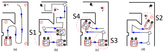
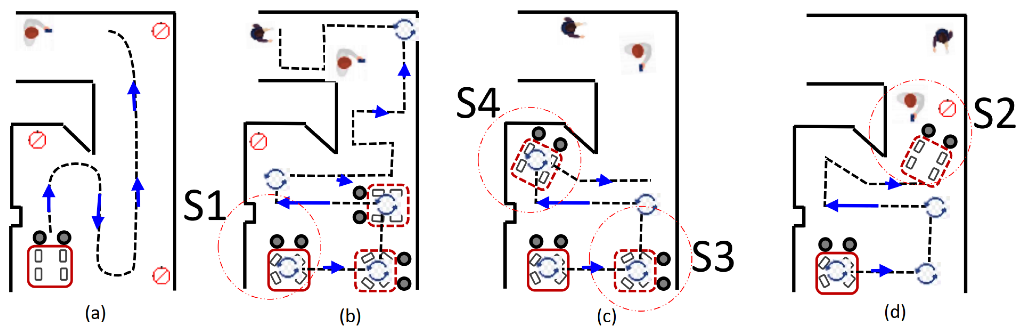
Figure 1.
Scenarios for the navigation during pavement sweeping task using cleaning and maintenance vehicles with (a) turning radius, (b) Omnidirectional feature using independent steering action on pavement settings, (c) Constraints at sharp corners by the ICR selection, and (d) obstacle near the turning routine of the robot. S1, S2, S3, and S4 are the scenarios mentioned in Section 1.
The scope for the application of reconfigurable robots in the domain of cleaning and maintenance in an unstructured environment is huge. The advantages of the reconfigurable robotic architecture include evolvability, multifunctionality, and survivability, along with its autonomy, which is detailed in [10]. The shape-changing robot for the floor cleaning task named hTetro is reported in [11] along with the energy calculation during the reconfiguration in [12], genetic algorithm-based complete path planning in [13], and reinforcement learning-based and bio-inspired neural network completed path planning in [14,15], evolutionary based path planing [16]. The other tiling-based reconfigurable platforms were proposed such as hexagon-based hTrihex [17], rhombus-based hTetran [18], polyiamond based hTetrakis [19] to overcome the coverage difficulties of the complex workspace shapes. The reconfigurable platform called Mantis [20] with the ability to change between panels to clear the glass façade vertical structure of the building has also demonstrated the flexibility of reconfigurable mechanism. The constraints of 4 wheels independent steering with the flexibility of freedoms between robot shapes are addressed in [21]. The challenges during navigation of these reconfigurable robots under the disturbance by monitoring the instantaneous center of rotation (ICR) are presented in [22]. The experiments in [22] showed the path tracking results for a single shape out of seven forms of hTetro under external disturbance. In the present work, the ICR coupled with the shape-changing ability of the Panthera robot across its width enhances the feasible space of ICR selection. This is exploited for selecting the optimal ICR while avoiding obstacles using sensory feedback during the navigation of the Panthera on the pavement settings.
The reconfigurable architecture for the pavement sweeping task was highlighted in [23,24], where the robot has differential wheels for the steering action. The design principles for the self-reconfigurable architecture for the modified design of the pavement sweeping robot using four wheel independent steering and drive (4WISD) [25,26,27,28] are detailed in [29,30]. Here, the authors highlighted the transformation principles used to design the sub-systems of the Panthera robot presented in this work. For brevity, the design of the Panthera is also discussed in the present work. Panthera consists of the mechanism supporting the reconfiguration to change its width, allowing the robot to move through narrow pavements when required, and enhanced area coverage during the cleaning operations. Moreover, it has a 4WISD model where the ICR during the locomotion can be selected anywhere in a two-dimensional (2D) space except the singularity occurring near the axis of steering units. Appropriate selection of ICR is challenging with complex local and global path planning.
Most research has been performed on fixed shape robots with fixed kinematic models based on Ackerman steering [31,32,33] and differential drive kinematics model [34,35,36,37]. Other examples of robots using ICR as part of their control and maneuvering using ICR are four independent steering drive and skid steering mobile robots [38,39,40]. However, their kinematic models for local planners do not incorporate ICR information to perform rotation within the robot footprint by checking the obstacle in the local path planner. In autonomous mobile robots, local planners are built to look for locomotion based on the obstacles around the robot.
In pavement sweeping mobile robots, the objective of the robot is to clean a large area and tends to move in a zig-zag pattern Figure 1b in order to increase area coverage. In a zig-zag global planner [41,42], waypoints are given to the robot for path following. It also has to follow the orientation of the waypoint. The reconstruction of the outdoor pavement environment for navigation purposes is reported in [43]. A survey of the approaches for sensing systems of environmental perception technologies for the driver-less vehicle is reviewed in [44]. The path control of the four Omni wheels mobile platform are studied in [45,46]. In the pavement environment, there are many obstacles, and some of these obstacles might inhibit the robot’s ability to perform rotation to achieve the desired heading angle of the waypoint in the global path planner. There are studies [47,48,49] focused on local planners that enable robots to avoid obstacles moving from waypoint to waypoint. Therefore, there is scope to study the planners that account for robot rotation in the constraint spaces by avoiding collisions.
The area coverage task using the global planner is prevalent in cleaning and maintenance robots. The modified A-star algorithm for the shape-shifting robot similar to hTetro was reported in [50]. Further, the incorporation of reinforcement learning-based techniques, including reconfiguration and locomotion planning, was studied in [14]. The optimization scheme for the efficient area coverage with the zig-zag motion is shown in [17]. However, the robot’s footprint was not accounted for during the reconfiguration task as the shape of these robots was small. Several schemes for the wall-following behavior of the robots are discussed in literature [51,52,53]. Wall following using sonar-based feedback control was demonstrated in [54]. These approaches focus on maintaining the constant distance from the side surface, whereas the fixed shape of the robot with the sharp turns and constraint spaces can result in the robot with situation S4 shown in Figure 1c.
In this work, the varying footprint ranging from 0.9 to 1.3 m in width is accounted for the optimal selection of ICR in order to avoid the obstacle and select the appropriate steering angle to avoid the collision. It enables Panthera to avoid pedestrians while moving, but it fails to consider the waypoint heading angle required by the global planner. When Panthera reaches a waypoint from the global planner, it needs to perform static rotation in order to perform zig-zag motion for cleaning operations. However, as there are many obstacles in the real-world environment, whenever Panthera rotation is blocked, it gets stuck and is unable to continue its cleaning operations. Panthera needs a rotation algorithm to enable it to navigate out of such scenarios.
There is little or no work reported on a local planner for anti-collision static rotation on a reconfigurable robot considering its varying footprint using the 4WISD model under the local planner. Without a proper local planner, a simple rotation of its axis can be potentially dangerous. If an obstacle in the form of construction around the pavement or pedestrian stands beside Panthera while performing static rotation about its axis, it will result in a collision. Taking into consideration the above description, the following objectives of the present paper:
- Kinematics modeling for the reconfiguring pavement cleaning and maintenance robot.
- Considering the region within the robot footprint for the selection of instantaneous center of rotation (ICR) in order to avoid collision in constrained spaces.
- Optimal selection of ICR for the static rotation to get the heading angle of the robot where there is no collision with the obstacles in the form of constrained spaces environment or standing pedestrians.
- Experimental demonstration of implemented ICR selection approach for reconfigurable robot performing rotation to navigate through tight spaces namely in four scenarios, (S1) Rotation while avoiding structural obstacles, (S2) Rotation while avoiding pedestrians, (S3) Rotation on a wide pavement, and (S4) No rotation possible, are shown in Figure 1.
The paper is structured into the following sections. Section 2 gives a brief description of the reconfigurable design of the robot for the pavement sweeping task referred to as Panthera. Section 3 describes the kinematics of Panthera, highlighting the modes of locomotion using ICR. Optimal selection of ICR from the feasible space within the robot footprint using multi-objective optimization approach, namely the Gradient Descent method in Section 4. The experimental results and discussion are detailed in Section 5. Section 6 concludes the paper with the scope of future works.
2. Robot Architecture
This section briefly highlights the layout of the self-reconfigurable robot Panthera in this work. The design of Panthera is categorized into the mechanical design, steering units, electrical system and sensors, reconfiguration design, and system design.
2.1. Mechanical Design
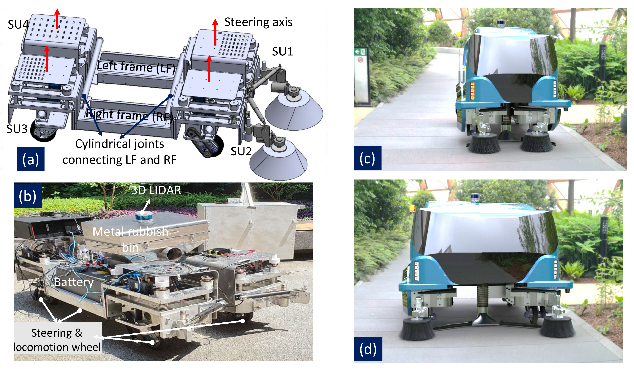
Panthera body consists of two parts, the left frame and the right frame, and joining the two side beams is a cylindrical joint, as seen in Figure 2a, which allows the reconfiguration of the robot width. The cylindrical joint allows the robot body to slide for the expand or compress action and is actuated by the steering units. Based on the steering unit’s direction of motion, it makes the cylindrical joint slide inwards for compression, outwards for expansion, or static, where the reconfiguration state of the robot remains the same. Two SIKO WV36M Wire Encoders are used to get the reconfiguration state of Panthera’s width.
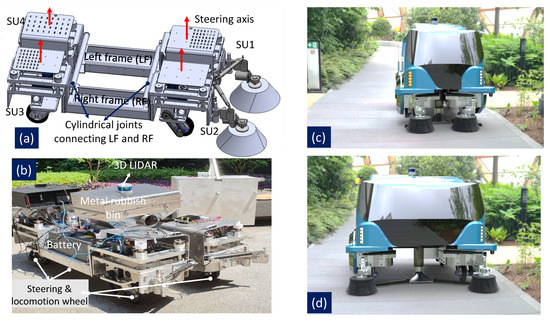
Figure 2.
Design or reconfigurable robot Panthera (a) Chassis, steering units (SU), and cylindrical joints connecting the left frame (LF) to the right frame (RF), (b) Skeleton of the robot on pavement, (c) Fully compressed state of the robot with width 0.9 m, and (d) Fully expanded state of the robot with width 1.3 m.
The cover of Panthera is in two parts, one attached to the left side frame while the other is attached to the right side frame as seen in Figure 2a. Panthera also has a cleaning unit system that consists of a vacuum motor, a rubbish bin, and two sweeping brushes. The rubbish bin is connected to a vacuum inlet which is controlled by a linear actuator. The linear actuator moves the vacuum inlet up and down depending on the type of litter it needs to vacuum. In addition, there are two linear actuators for the sweeping brushes to move them in and out to change the range of the sweeping brushes. Overall, Panthera has a total of ten motors where four motors are used to perform independent steering of the steering units, four motors are used to perform translation of the wheels, and two motors are used for turning the sweeping brushes. Panthera has a four steering unit design, each containing an independent steering and independent translation motors.
2.2. Steering Unit Design
Panthera has four independent steering units, , , and , which are controlled using an Oriental Motor BLV200. Each individual steering unit has a SIKO WV58MR absolute encoder for accurate steering angle feedback. The steering motor uses the angular feedback from the encoder to perform a Proportional Integral and Differential (PID) control. The omnidirectional movement is governed by each steering unit which can rotate in both clockwise and anti-clockwise directions while the translation motors help the robot move in the desired direction. Similarly, this enables Panthera to perform zero turning radius rotation and rotate about a given ICR. For Panthera to perform such complex movements, the steering units and translation motors have to work synchronously to prevent wheels from slipping or sliding, as accounted in the robot kinematics in Section 3.
2.3. Electrical System and Sensors
Panthera is powered by two 24 V 206 Ah batteries. The two power supplies are decoupled with one battery powering locomotion and steering actuators while the other battery powers the suction and sweeping brush actuators. The locomotion system and the cleaning unit are designed to have two separate batteries as the cleaning unit is expected to use more power than the locomotion system. Therefore, when the battery that supports the cleaning unit system is low with charge, there is remaining power for Panthera to perform locomotion back to its charging station.
The battery that powers the locomotion system also powers all the essential sensors for Panthera’s autonomy. These sensors include XSens MTI 680 IMU/GNSS, Velodyne, and Ouster LiDARs, UCC4000 Pepperl and Fuchs ultrasonic sensors, SIKO WV58MR absolute encoder, WV36M wire encoder, and ZED camera. All these sensors are used to perceive the surroundings, localization, vision detection, and control feedback.
2.4. System Design
The Robot Operating System (ROS) is used for data transmission and processing of the information of the sensor. ROS Melodic is running on the onboard computer, which has the following specifications of 8 CPU Cores, 16 GB RAM, and RTX1060 GPU. All the linear actuators and the two sweeping brushes are controlled via RoboClaw, connected to the onboard computer. All sensors are connected directly to the onboard computer via USB or Ethernet ports. All data from the sensors are published as ROS Topics while the data processing is computed in the ROS Nodes. Multiple ROS Nodes are running in parallel for different functions such as localization, cost map generation, and optimization of ICR. ROS allows Panthera to process data parallelly so that it can dynamically adapt to the requirements of the surroundings, such as in the case of an optimized steering angle for its independent steering units for safe maneuvering.
3. Robot Kinematics
This section discusses the kinematics of Panthera. The rotation kinematics can be used to position ICR in the two dimensional space within and outside the robot footprint space except for the steering axis location of the wheels.
3.1. Kinematic Model
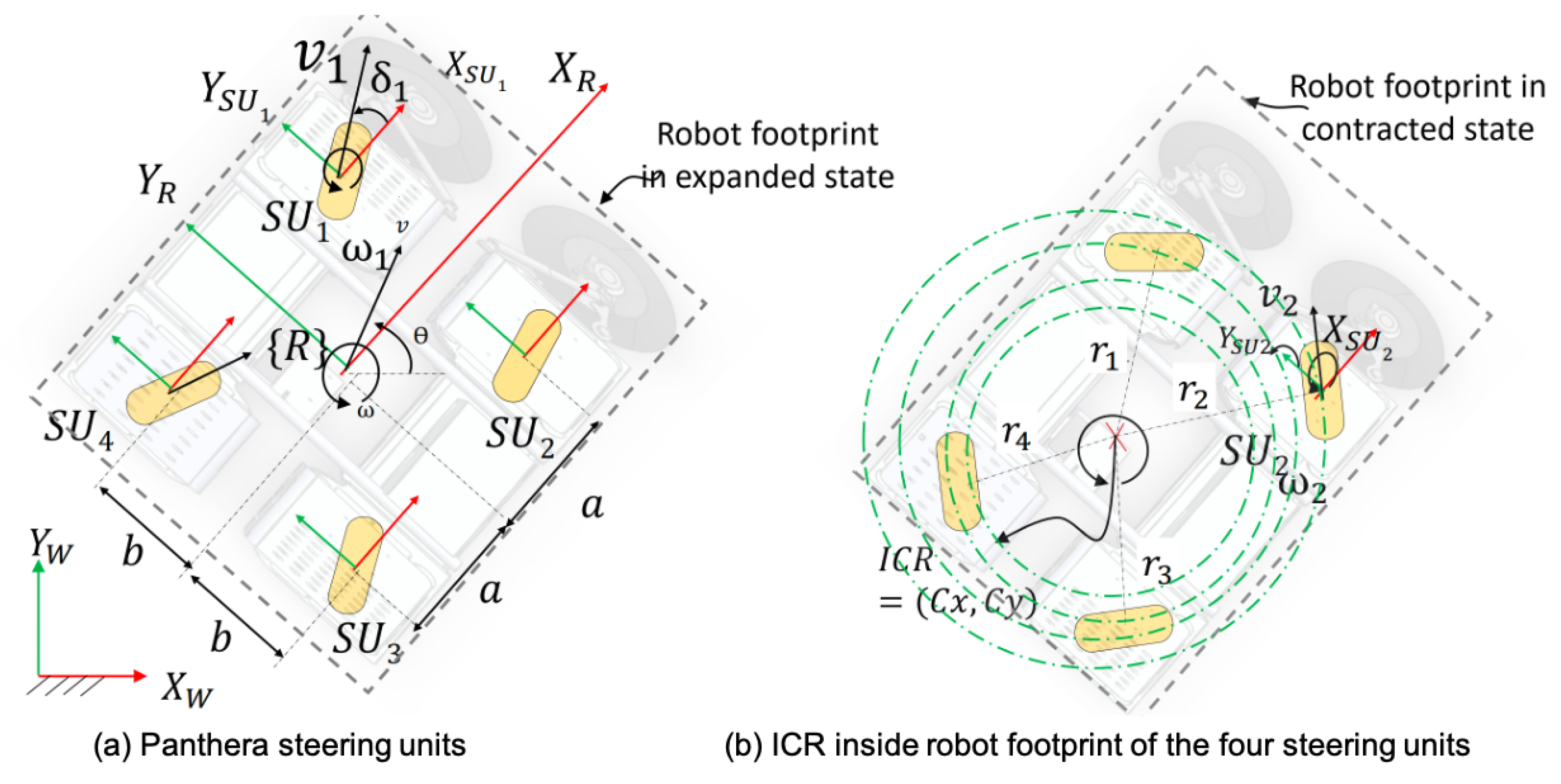
The four steering units (SU) as , , and are shown in seen in Figure 3a where its location from the robot frame R are defined as ; ; ; . Here the parameter of width, i.e., b is variable since the robot can reconfigure and takes the value from 0.35 to 0.65 m. The distance from the midpoint to the steering unit, a, is fixed at 0.45 m. The four wheel independent steering and locomotion are governed by the following Equation (1):
where C and S, are sine and cosine functions, is defined as the velocity vector as in the world coordinate and where is the index of steering unit, and .
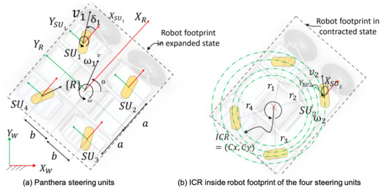
Figure 3.
Panthera steering units and ICR.
For interested readers, Panthera’s dynamics modeling can be found in Appendix A.
3.2. Instantaneous Center of Rotation
The instantaneous center of rotation (ICR) is the point at which steering units rotate about. The ICR of each respective steering unit is , where is the radius of rotation curve from the ICR to axis of the steering unit in the robot frame . In terms of the robot coordinate frame, ICR for the respective steering unit is as follows Equation (2):
It can also be represented in the world coordinate frame [55] as follows Equation (3):
where is the rotation matrix about the Z-axis. In the robot coordinate frame, depending on the coordinate of the ICR of the respective steering units, it is able to achieve different modes of locomotion as discussed below:
- Mode 1: When all or robot performs a straight line movement. When or , it moves along the robot y-axis. When or , it moves along the robot x-axis.
- Mode 2: When all , robot performs a static rotation about the geometric center of the robot.
- Mode 3: When all or , where and are real constants, robot performs a circular motion where the ICR is perpendicular or parallel to the robot orientation.
- Mode 4: When all , where and are real constants, the robot performs a circular motion where the ICR can be anywhere in space except the position of its wheels.
Mode 1, 2, and 3 are subsets of Mode 4. In this work, constrained Mode 4 is interested where the ICR is within the robot’s footprint for local planning. Other locomotion models, such as four wheel differential drive, skid drive, and Ackerman models, cannot perform Mode 4 locomotion. Mode 4 locomotion is advantageous as it enables Panthera to perform a static rotation where the ICR is not at the center of the robot, as seen in Figure 3b. The circular lines are the circular path that each steering unit follows in Mode 4 locomotion.
In the next section, the optimization of the ICR using the constrained Mode 4 locomotion leveraging the reconfigurable abilities to enable Panthera to navigate through tight spaces is described.
4. Multi-Objective Optimization for ICR Selection in Local Planner
The proposed ICR optimization approach consists of deriving the optimal ICR based on the constraints of Panthera’s footprint and environment and the objective function. The constraints of Panthera’s footprint and environment are incorporated into the approach to quickly identify the feasible ICR space where Panthera can perform rotation using the constrained Mode 4 locomotion. Feasible ICR space is a space that includes possible ICR, which is deemed safe for the robot to perform the constrained Mode 4 locomotion, taking into account factors such as obstacles, rotation target angles, and safety buffer. Based on the set of feasible ICR space, a multi-objective function is used to evaluate the optimal ICR.
The flow chart in Figure 4 consists of two main steps, including the identification of a feasible ICR space and the optimization of ICR based on a multi-objective function. The input to the proposed algorithm is , which is the difference between the current heading angle of the robot and the global planner waypoint target heading angle. In the first step of our proposed algorithm, a feasible search space for ICR is identified by adjusting the discrete reconfigurable state (width of the robot footprint size inside the grid workspace). Then, after defining the multi-objective function for steering angle, clearance, and distance, the 2D coordinate of optimal ICR within the found candidate region is derived. The following two sub-sections describe the two steps of our proposed approach in detail.
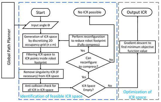
Figure 4.
Flowchart for proposed ICR optimization.
4.1. Identification of Feasible ICR Space
Besides reducing the searching area, identifying feasible ICR space is also to ensure that when the robot performs the locomotion about the ICR, it is safe and is anti-collision. The identification of feasible ICR is determined through the constraints of the robot and its environment perception from sensor feedback. In the Panthera, the objective of the robot is to perform cleaning while navigating through tight spaces that other fixed shape robots are incapable of implementing. To navigate out of tight spaces, it has to rotate in a fine manner by an input angle, . If the space is too tight for its reconfiguration state, it might need to reconfigure and reduce its width, b. Furthermore, it has to avoid obstacles based on the local cost map and the robot’s footprint. Therefore, it is concluded that the feasible ICR space is determined by its input angle, , and its reconfiguration state, b, and the local cost map.
4.1.1. Local Cost Map and Robot Footprint
The local cost map is built based on Panthera’s perception sensors. Panthera uses three dimensional LIDAR to determine obstacles in its surroundings. Velodyne VLP 16 is used to build a grid-based cost map, as seen in Figure 5, where the grid size and resolution can be predefined. Smaller grid size and lower resolution is recommended to reduce computational complexity.
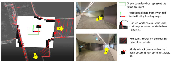
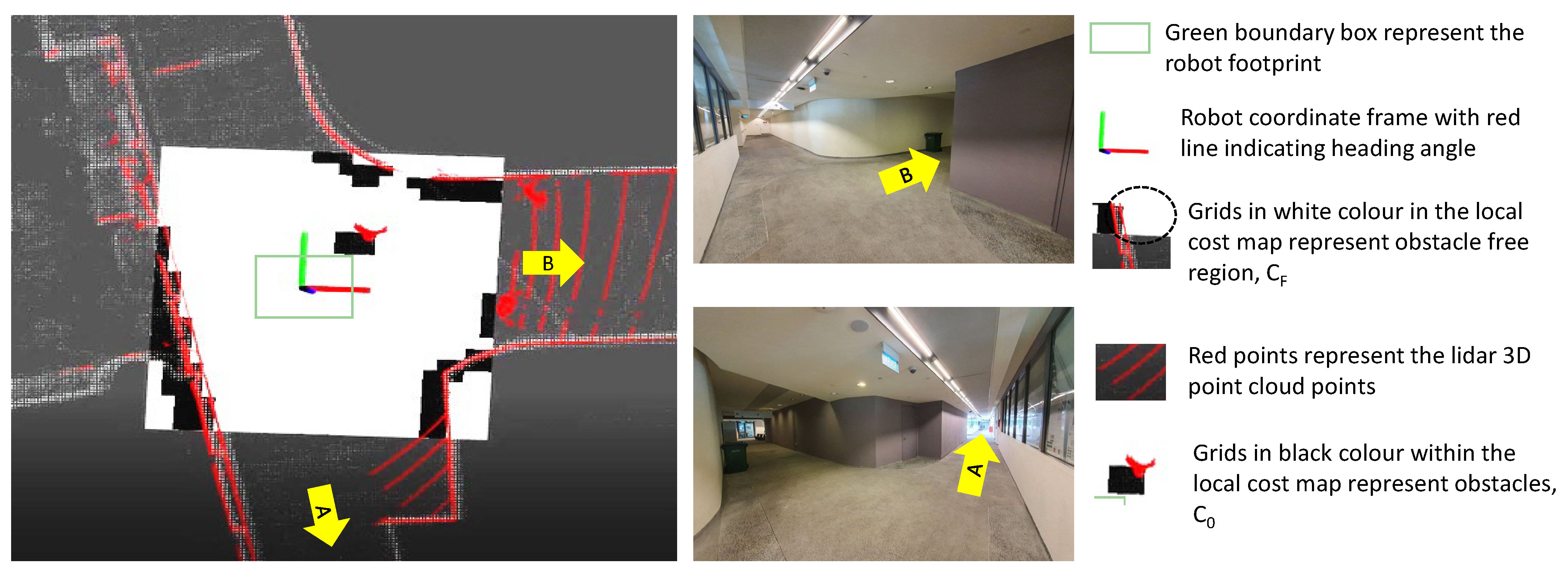
Figure 5.
Local Cost Map (the black-colored points map with the obstacle boundary).
In Figure 5, the black region of the cost map is the obstacle, while the white part is the obstacle-free area. A and B are the regions of corridors The red-colored dotted points represent the point cloud from LIDAR, the green boundary box represents the robot footprint, and the red axis line arrow represents the robot’s heading angle. Surrounding the local cost map is the global 2D cost map. In the local cost map, cost map size and resolution can be tuned. The robot is always in the middle of the local cost map. The robot ICR space is a mathematical space for all discrete values of ICR that Panthera has based on the grid base cost map. It consists of different kinds of regions: the feasible moving region , where there are no obstacles, and non-feasible moving region, , which represents obstacles where
In Equation (4), it is assumed that the ICR space can be discretized into a grid of squares. Based on the feasible region of locomotion, initialization of the ICR space by using the discrete points within the grid base cost map and the robot footprint. After which, grids with ICR points or or or are excluded as that is where singularity of the kinematics model occurs.
4.1.2. Panthera Reconfiguration State and Robot Footprint
Panthera has the ability to reconfigure in its width, and as a result, the footprint of the robot varies. Panthera has a wire encoder, SIKO WV36M SG21 Wire Encoder, to get the state of reconfiguration width, b. Based on the sensor feedback, the respective robot footprint is used as part of the robot constraint. The initialized ICR space is constrained by the footprint of the robot, as seen in the Equation (5):
where , , and represents the minimum and maximum dimensions of the robot footprint in the x and y robot coordinate based on the robot reconfiguration state, b. As seen in Figure 5, the green-colored rectangular box represents the robot footprint. Therefore, the obstacle region of the cost map should not intersect the robot footprint. Otherwise, it is considered a collision.
4.1.3. ICR Trajectory Collision Check
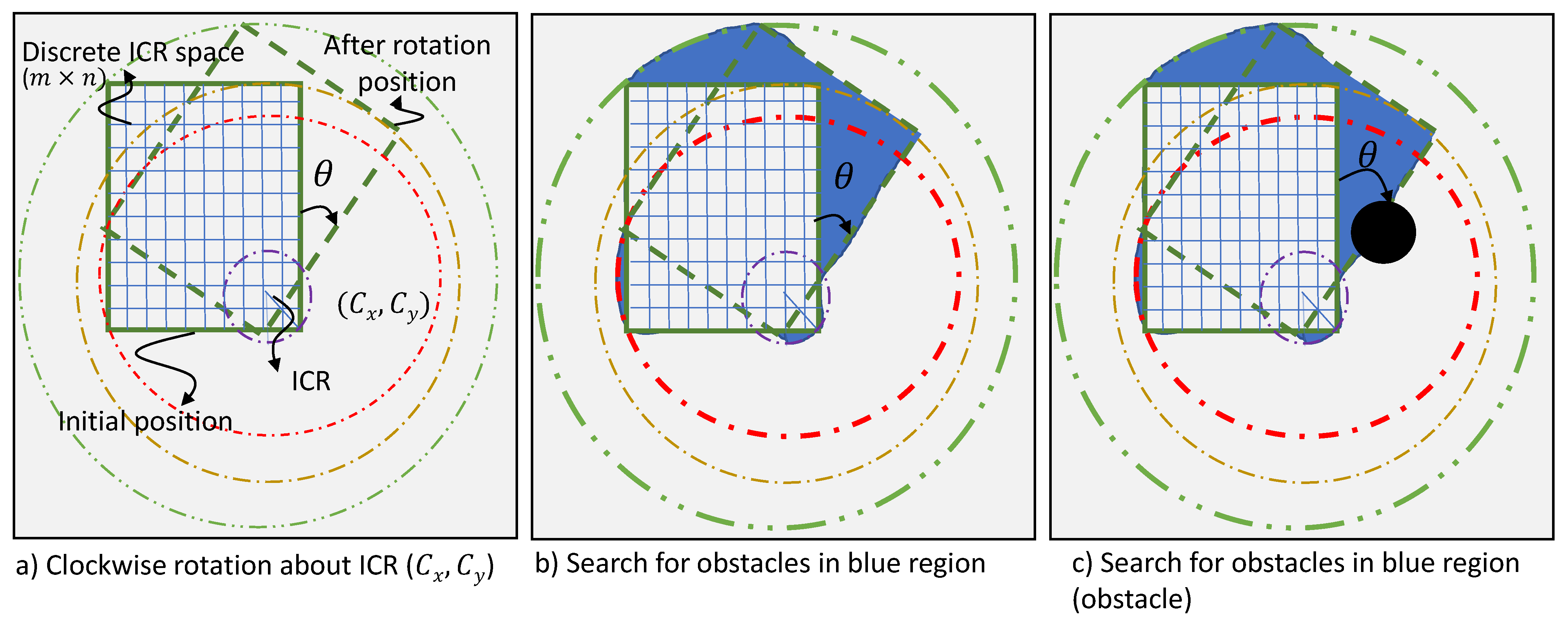
As shown in Panthera’s rotation kinematics, Panthera is capable of performing rotation about an ICR with 4 modes of locomotion. To optimize Panthera’s rotation in a tight environment, there is a need to further reduce the ICR space into a feasible space where the rotation of the robot footprint does not encounter any obstacles. To perform a rotation, the ICR have coordinates where , where and are real values. Furthermore, based on the input angle, , it may or may not collide with surrounding obstacles. After initializing the ICR space and the robot reconfiguration state, b, the algorithm reduces the ICR space by performing checks when the robot footprint is rotated about the ICR by the change in robot heading angle, , as seen in Figure 6a. The blue grids represent the discrete ICR space that is used to perform the trajectory collision check. For a clockwise rotation about the ICR, the robot has to check the cost map in the blue region as seen in Figure 6b by searching all the cells within the blue region for obstacles. If it encounters an obstacle, such as in Figure 6c, the discrete ICR value is removed from the ICR Space. Rotation about ICR trajectory collision check removes all ICR where there is the possibility of collisions. This leaves an ICR Space where there is no possibility of collision.
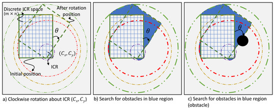
Figure 6.
Search for feasible ICR within the robot footprint and collision check.
If there is no possible ICR for the rotation to occur without collision, the ICR space is an empty set. Subsequently, it checks for its current reconfiguration state, b, and if it is not fully compressed, the algorithm iterates with a smaller reconfiguration state, b, where the robot footprint is smaller. If the algorithm still gives an empty set for the smallest reconfiguration state, the algorithm stops as there is no possible ICR for a safe static rotation. If the ICR space is not empty after the anti-collision check, it is passed to an optimizer described in the following sub-section.
It is noted that Panthera is able to change its reconfiguration state, b, and has multiple modes of reconfiguration, which is not optimized in this paper. In our proposed algorithm, it is assumed that Panthera reconfigures to the center to the smallest reconfiguration state if it needs to perform reconfiguration during the identification of ICR space.
4.2. Minimising Objective Function Using Gradient Descent
After determining the ICR space where there are no collisions at a discrete reconfiguration state, b, the optimal ICR is selected based on the minimization of a multi-objective function. The multi-objective function incorporates the steering angle of the steering units and the clearance from obstacles, and ICR’s distance from the robot’s geometric center, as seen in the Equation (6):
where the objective function, , is the combination of weighted steering angle function, , clearance function, and distance function, . , and are weights corresponding to the steering angle function, , clearance function, and distance function, , respectively. More details of the objective functions are described in the next few sub-sections. The robot feedbacks its current steering unit heading angle, position, cost map, and the multi-objective function trade-off between minimizing the change of steering unit heading angle and the clearance space that the robot has after rotation. Although it is possible to evaluate the multi-objective function using the ICR space to find the global minimum, it is not feasible for a high-resolution grid-based cost map where the number of discrete ICR points increases quadratically with the resolution of the map. Therefore, gradient descent is used to evaluate the optimal objective function.
4.2.1. Steering Angle Function
The steering angle function goal is to reduce the summation of the change of steering angle for each steering unit. As the robot is deployed, reducing unnecessary rotation reduces wear and tear of wheels and steering motors.
The SIKO WV58MR absolute encoder gives the current steering angle for the steering units. The steering angle function is defined in the Equation (9).
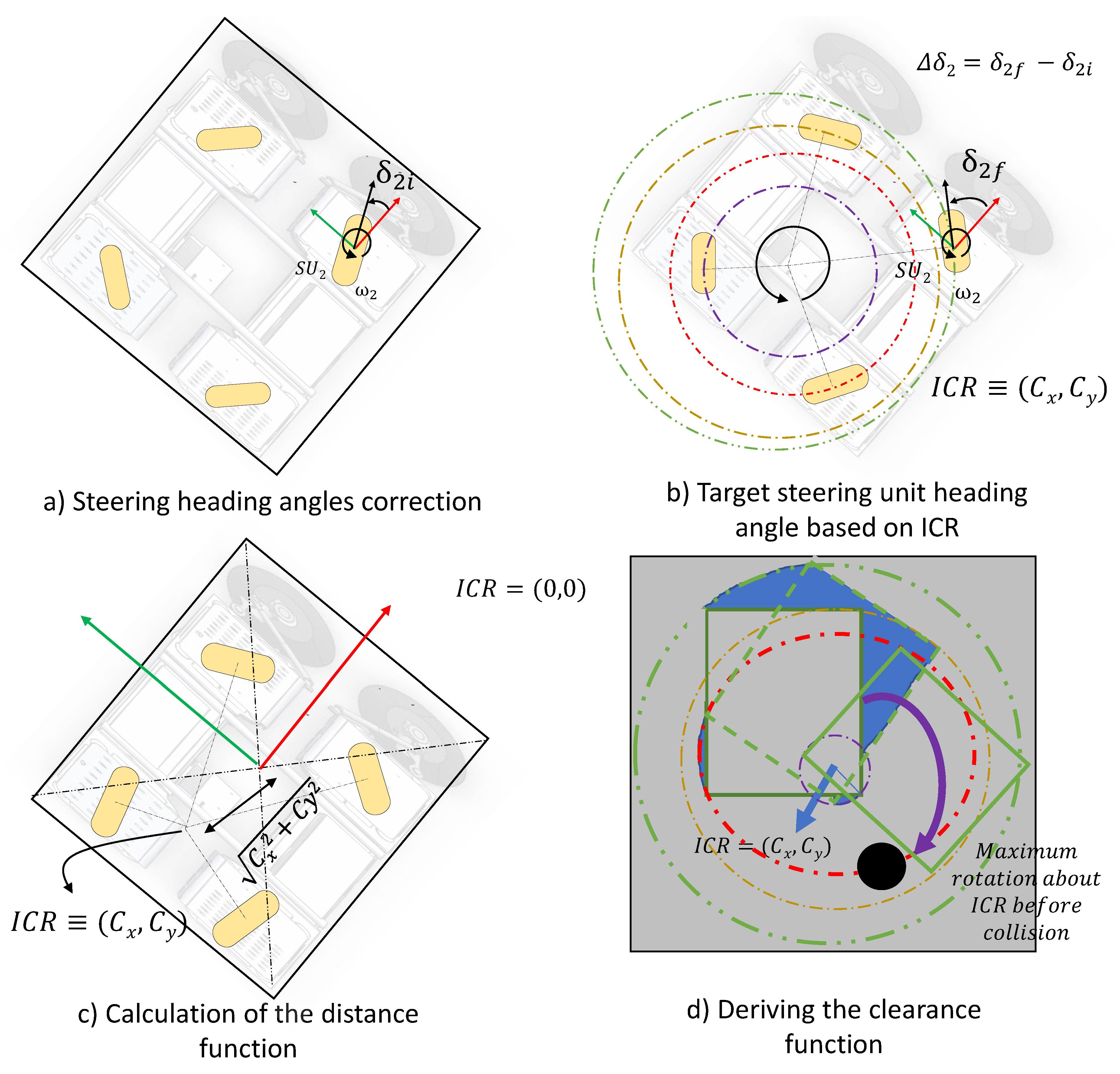
where is the difference between the current steering angle and targeted steering angle based on the ICR as seen in Figure 7a,b. This function minimizes unnecessary rotation of steering units and reduces the power required to make a safe rotation.
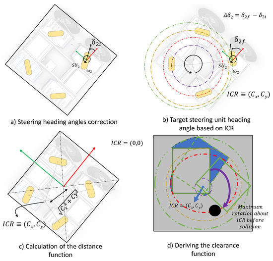
Figure 7.
Visualisation of the objective functions.
4.2.2. Clearance Function
The clearance function, represents the maximum rotation about the ICR before the robot encounters the surrounding obstacles as seen in Figure 7d. The Equation (8) works similarly to the searching of ICR space for collision check to ensure the obstacle avoiding while rotating, as seen earlier in Figure 5.
where:
where s is the step size of the clearance checked in degrees and is the anti-collision check for an increment of f degrees of rotation about ICR. After which, it is converted to radians.
If there are no obstacles in the direction of rotation, the value of the function is set to 2. This function acts as a safety for the robot and the surroundings. Since the constraints in rotation resolution of robot locomotion and to reduce the computational cost, Panthera performs the clearance function where it checks with anti-collision rotation of an increment step size in degree, s, of 5 degrees as the example in the experimental section.
4.2.3. Distance Function
The distance function, represents distance between the ICR and the geometric center of the robot as seen in Figure 7c. The function is the magnitude of the vector between the ICR and the geometric center of the robot, as seen in the Equation (9):
This is to push the ICR closer to the center of the robot so that it does not deviate too far from its position during the rotation. This also ensures more safety as the robot’s position after rotation is closer to its initial position and prevents the robot from swinging too far from its initial position.
The weights of the steering angle function, clearance function, and distance function can be tuned to give more importance to the function. For example, if the distance function is more important, set the value and . In application, a fixed set of weights are pre-tuned for operation.
In the next section, the experimental results of our proposed algorithm are discussed.
5. Experimental Results and Discussion
The performance and results of the proposed algorithm are evaluated through implementation on Panthera in real-world applications. Four experiments were conducted to demonstrate the performance of the optimal ICR with Panthera reconfigurable mechanism and result in scenarios as shown in Figure 1. In all the experiments, Panthera starts from a stationary position with the direction of the steering units parallel to the robot’s body. It is assumed that all obstacles are static, including a pedestrian. For the robot to perform a rotation about the ICR, the steering units turn to the target angle based on the optimal ICR before the translation motor starts to perform the static rotation. To ensure that the robot performs the rotation about the ICR smoothly, a Proportional Integral and Derivative (PID) controller [56] is used to ensure that there is little error between the input linear velocities and the actual linear velocity of Panthera as a huge error can cause a jerk to the robot, potentially damaging it. The experiment is performed by the onboard computer described in Section 2.4.
5.1. Experiments
Robotic operating system (ROS) master sets up the connection between multiple computational ROS nodes. A Velodyne VLP 16 lidar is used to generate the local cost map and publish/cost_map topic. The local cost map generated has a grid size of 100 by 100 with a resolution of 0.05 m per grid. The inflation in the cost map is set low as Panthera needs to be close to walls to perform cleaning. It also has stable control with quality sensors to feedback on its position accurately. Based on the cost map and Equation (4), the grid is defined as the ICR space C. The identification of feasible ICR space ROS node subscribes to the /cost_map topic where it removes discrete ICR points outside of the robot footprint, singularity ICR points, and ICR points where collisions are detected. If an empty ICR space is detected, it repeats the identification of feasible ICR space with the smallest reconfiguration state to check if there are possible ICR in their smallest state. If a non-empty ICR space is derived, it performs a reconfiguration to the center of the robot. The identification of feasible ICR node publishes an array of ICR via the topic/ICR_space topic. The optimization node subscribes from the/ICR_space topic. It performs optimization based on predefined weights of the multi-objective function in Equation (6) using the gradient descent method. The optimization node publishes the ICR to the locomotion node for Panthera to perform rotation. A high-level ROS architecture implemented in Panthera can be seen in Figure 8. In all experiments, to reduce computational cost in its implementation, the clearance function checks in a resolution of 5 degrees of rotation clearance per iteration.
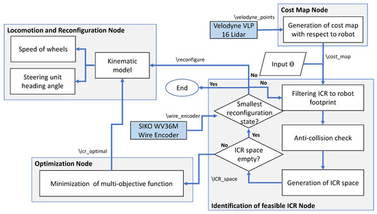
Figure 8.
ROS nodes and topics developed for self-reconfigurable robot Panthera.
In the following subsections, the results of the 4 experiments similar to scenarios found in Figure 1 are shown and demonstrated. The supporting video for the experiment can be found in the footnote. (https://drive.google.com/file/d/18psIKtHy4O6UB-6nPwIadKaYpZirZNp5/view?usp=sharing, accessed on 2 August 2022) or see Supplementary Materials.
5.1.1. Scenario 1: Rotation While Avoiding Structural Obstacles
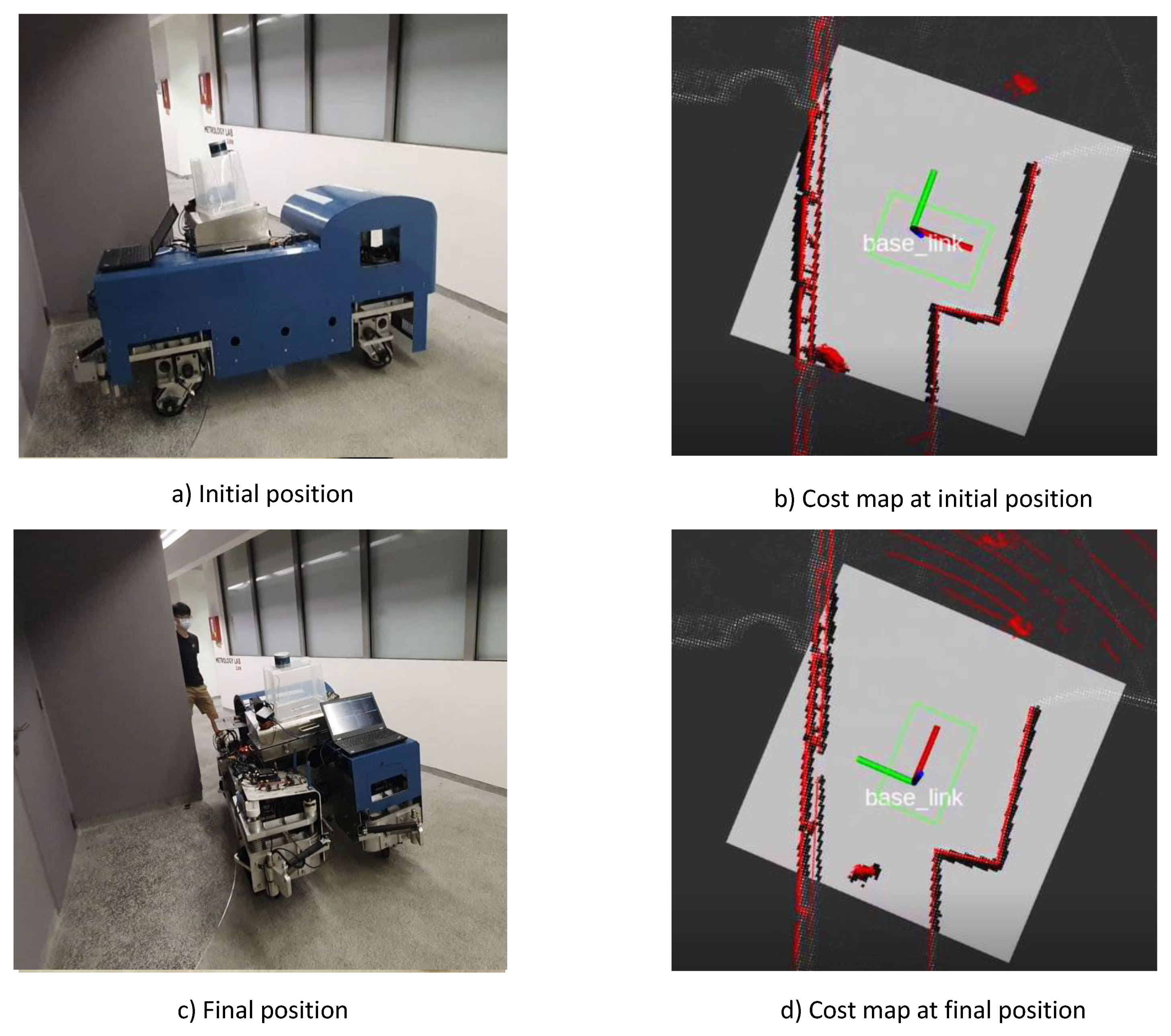
This experiment aims to demonstrate Panthera’s collision-free rotation performance when it is near two adjacent walls. Figure 9a shows the experiment setup and initial position of the experiment. Panthera is in the fully compressed state and is facing a wall with an adjacent wall to its right, as reflected in the local cost map seen in Figure 9b. The experiments follow a similar representation as found in Figure 5. If Panthera performs an anti-clockwise rotation about its geometrical center, Panthera’s back will hit the wall after a 90 degrees rotation.

Figure 9.
Rotation near a wall depicting Scenario S2 (Figure 1).
A weight of , and is used in this experiment. In this experiment, Panthera is commanded to turn 90 degrees anti-clockwise using our proposed algorithm for collision check and ICR optimization. Panthera performs 90 degrees anti-clockwise rotation about the optimal ICR smoothly without hitting the adjacent wall to its right, as seen in Figure 9c,d.
5.1.2. Scenario 2: Rotation while Avoiding Pedestrians
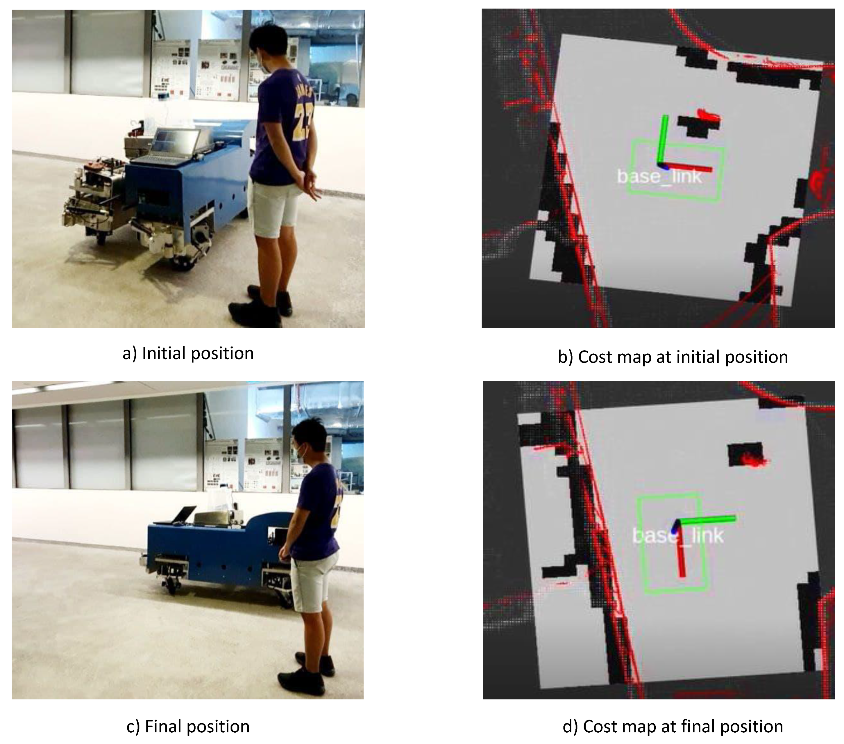
This experiment aims to demonstrate Panthera’s collision-free rotation performance when it is near a pedestrian. Figure 10 shows the experimental setup and initial position of the experiment. Panthera is in the fully compressed state and is along a walkway with a pedestrian on its left, as reflected in the local cost map seen in Figure 10b. If Panthera performs a clockwise rotation about its geometrical center, it will hit the pedestrian after a 90 degrees rotation.
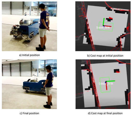
Figure 10.
Rotation awhile avoiding pedestrians depicting Scenario S2 (Figure 1).
A weight of , and is used in this experiment. In this experiment, Panthera is commanded to turn 90 degrees clockwise using our proposed algorithm for collision check and ICR optimization. Panthera performs a 90 degrees clockwise rotation about the optimal ICR smoothly without hitting the pedestrian on the left as seen in Figure 10c,d.
5.1.3. Scenario 3: Rotation on a Wide Pavement
This experiment aims to demonstrate Panthera’s collision-free rotation performance when in a wide path. Figure 11 shows the experimental setup and initial position of the experiment. Panthera is along a wide walkway as reflected in the local cost map seen in Figure 11b.
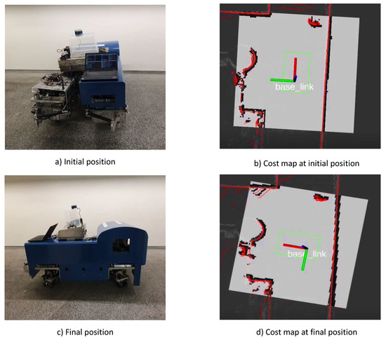
Figure 11.
Rotation in a wide pavement depicting Scenario S3 (Figure 1).
A weight of , and is used in this experiment. In this experiment, Panthera is commanded to turn 90 degrees anti-clockwise using our proposed algorithm for collision check and ICR optimization. Panthera performs a 90 degrees clockwise rotation about the optimal ICR smoothly without any collision as seen in Figure 11c,d.
5.1.4. Scenario 4: No Rotation Possible
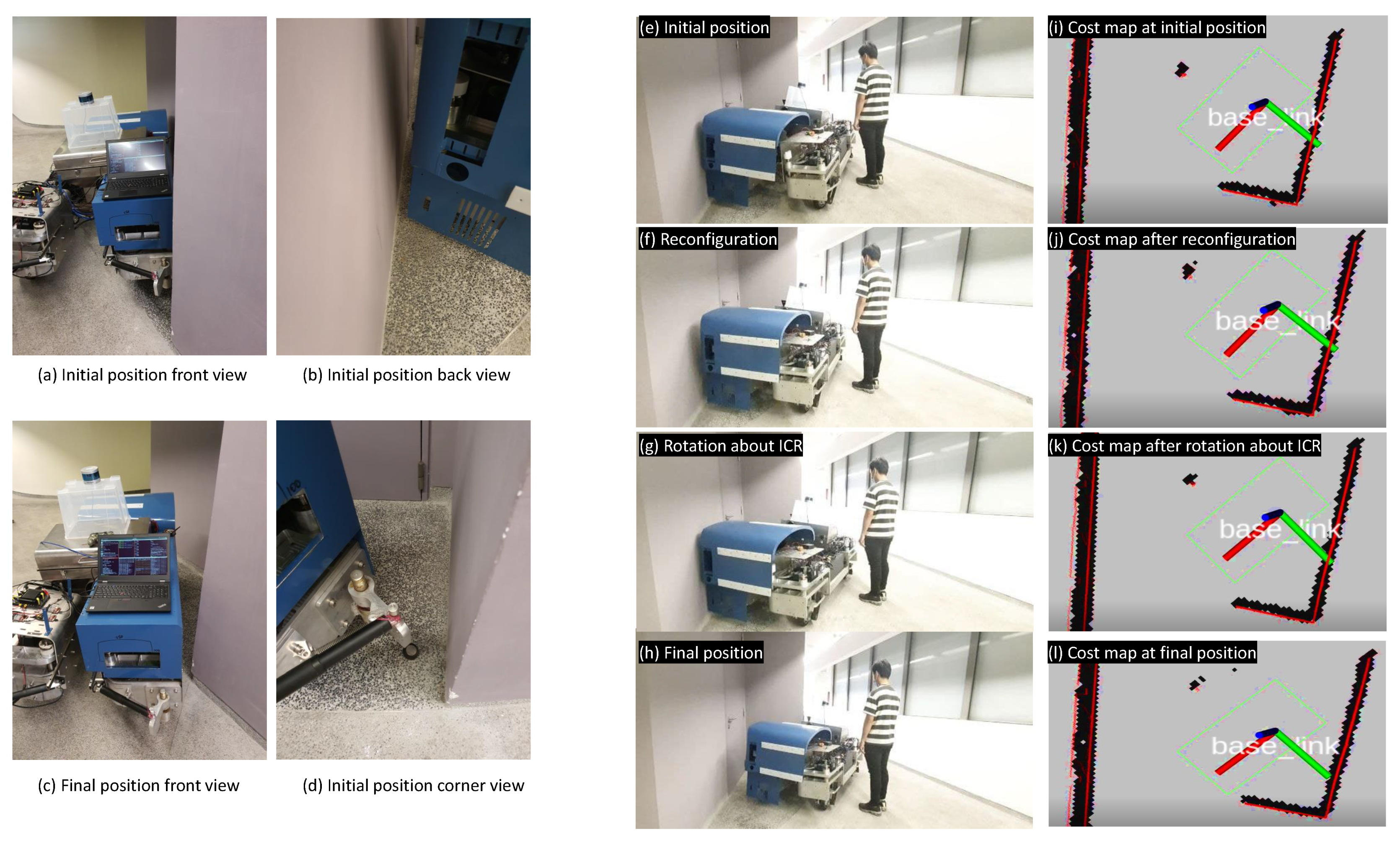
Unable to conduct the rotation is an issue for a fixed shape robot when it is completely surrounded by static and dynamic obstacles. However, using the 4WISD mechanism incorporated with reconfiguration ability while selecting the flexibility ICR within the robot footprint, Panthera is able to navigate out of the “impossible” scenario. Figure 12a,b,d,e shows the experimental set up and its initial position of the experiment to demonstrate the infeasible rotation condition for other fixed shape robots even with the 4WISD kinematics model. Panthera is set in the fully expanded state and is close to two adjacent walls and a pedestrian, making any static rotation impossible at its current reconfiguration state. Figure 12i shows the zoom-in cost map at the start of the experiment. The cost map is zoomed in for better visualization of the robot’s footprint and movements.
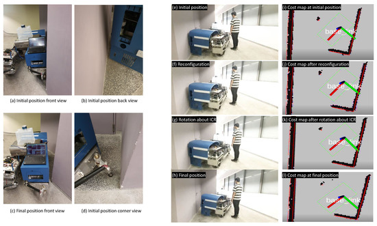
Figure 12.
No rotation possible with fixed form robots depicting Scenario S4 (Figure 1).
A weight of , and is used in this experiment. Panthera is commanded to rotate 10 degrees clockwise using our proposed algorithm and then move straight to navigate out of the situation. In the first iteration of the identification of the ICR space algorithm, it finds no possible ICR. It checks its reconfiguration state, b. As Panthera is in the fully expanded state, it performs a static reconfiguration to its center to its fully compressed state, which reduces the robot’s footprint as seen in Figure 12f,j. It repeats the identification of feasible ICR space algorithm and optimizes the ICR based on the multi-objective function. Panthera performs static rotation based on the optimized ICR in Figure 12g,k by 10 degrees. After completing the static rotation, it moves straight to navigate out of the tight situation, which is impossible for fixed shape robots as seen in Figure 12h,l.
In this experiment, Panthera is made to reconfigure in width and subsequently a static rotation smoothly without any collision, which would not have been possible for a fixed shape pavement sweeper. It is noted that Panthera has the ability to perform different gaits of reconfiguration [56] where it can compress to the left, compress to the right or any position between the two ends of Panthera. This ability gives Panthera flexibility in reducing its footprint, allowing rotation about an ICR to conduct smoothly. To simplify the optimization, the reconfiguration gait is selected for any position between the two ends of Panthera.
5.2. Discussion
Table 1 shows the values of the objective function with different weights for the experiments above. Experiments 1, 2, 3, and 4 represent the experiment for scenarios 1, 2, 3, and 4, respectively. The objective function is minimized such that the lower the value, the more optimal. Based on Equation (6), the optimal objective functions , , , and h are calculated using variations of weight factors , , and as shown in the third column. These weights are important as it affects how the robot behaves and tuning of weights directly affects how the robot behaves. For example, in Panthera’s autonomy implementation, more weight is given to to ensure that it remains close to the global planner target waypoint during rotation. For a holistic comparison, each optimal ICR objective function value is listed in Table 1. In a multi-objective function, increasing the weights of the desired objective function reduces the weightage of the remaining objective function. For example, for best clearance function optimization, = = 0. It is observed that in experiments 1 and 2, rotation about its geometric center results in a collision with an obstacle. Correspondingly, even with the best distance function where = = 0, is not 0. On the other hand, when Panthera is in a wide open path or when reconfiguration to compress occurs, the best distance function = 0.

Table 1.
Multi-objective functions with suitable weights.
In Table 2, the time cost for the identification of feasible ICR space (Step 1), gradient descent optimization, and a brute force search method to find optimal ICR based on the multi-objective function in a scenario similar to experiment 3 with input angle 10 degrees and is tabulated against the resolution of the local cost map which represents a 10 m by 10 m space in the real world. A weight of , and is used. The time cost for identifying ICR space is 0.31 s and 109.4 s for the 0.05 m and 0.01 m resolution cost map, respectively. For the 0.05 m resolution local cost map, the optimization of the objective function was 1.3 s, and the search method was similar at 7.52 s. However, due to the much higher total number of ICR points found in the higher resolution cost map of 0.01 m, the gradient descent method takes about 1.9 s and outperforms the speed of the search method at 2417.1 s. For a higher resolution, the computational cost for the optimization goes up, and a gradient descent method offers much better computational speed as compared to a brute force minimization algorithm such as the search method. Although a higher resolution cost map potentially offers better ICR optimization, lower-cost map resolution is recommended as the optimized ICR is anti-collision in nature. Any solution, even a non-optimal solution, within the feasible ICR space is anti-collision in nature due to the design of the anti-collision check. It is noted that as the resolution is about 5 times different, the expected number of feasible ICR is also about 25 times bigger in the higher resolution cost map. However, this is not the case for the time cost for the identification of feasible ICR space, gradient descent method, and search method.
Table 2.
Time for computation during optimization using gradient-descent (GD) and brute force search (BFS) method.
During our ICR experiments, it is noted that our proposed algorithm require additional constraints based on Panthera’s motor limitations where . In order to compensate for the translation motor speed range, a higher distance function weight is used so that all its translation motors experience a smaller range of speed. Furthermore, normalization of objective functions was considered but not implemented because tuning of weights still needs to be performed for different robots and environments. However, if required, one way to perform normalization is to normalize and against 2 and against the maximum distance ICR can have based on robot footprint. This is due to the nature of the respective objective functions, which depend on rotation and distance, respectively.
It is also important to note that the implementation of the proposed algorithm requires robust robot control. In Panthera, a PID controller is used to ensure low error between control inputs and actual control measurements. If the control implemented is not stable, build of up errors can lead to dragging of wheels, rubbing of wheels, and even motor failure [29].
6. Conclusions and Future Work
This paper presented a 4WISD reconfigurable robot which performs navigation through tight and confined spaces using rotation about its instantaneous center of rotation (ICR). The ICR is selected optimally within the robot footprint. We implemented the proposed framework in the self-reconfigurable robot named Panthera as a case study. The kinematics for rotation about an ICR, identification of feasible ICR space, and the optimization of the ICR through gradient descent is described. Changing the weights on the gradient descent function helps to tailor the steering unit function, clearance function, and distance function. Moreover, the paper also demonstrated the advantages of how a reconfigurable robot is able to adjust attentively its footprint and perform static rotation in comparison with fixed form robots in unable navigation scenarios. Our future works focus on optimizing reconfiguration gait to maximize area coverage while performing static rotation about its ICR in different reconfigurable platforms. Other future works include analyzing the optimization methods using other types of modern optimization based on the multi-objective function so as to improve the computational cost required to achieve the optimal result. Optimal ICR for robots with more independent steering and driving is also potential future research.
Supplementary Materials
The following supporting information can be downloaded at: https://www.mdpi.com/article/10.3390/math10173169/s1.
Author Contributions
Conceptualization, A.V.L.; data curation, L.Y., A.V.L., K.L. and K.E.; formal analysis, L.Y., A.A.H. and M.T.; methodology, K.E.; project administration, R.E.M.; resources, B.R. and R.E.M.; software, L.Y., J.C.C.H., K.L. and M.V.B.; visualization, P.V.D.; writing—original draft, L.Y., M.V.B. and P.V.D.; writing—review and editing, A.V.L., A.A.H., B.R., R.E.M. and M.T. All authors have read and agreed to the published version of the manuscript.
Funding
This research is supported by the National Robotics Programme under its Robotics Enabling Capabilities and Technologies (Funding Agency Project No. 192 25 00051), National Robotics Programme under its Robot Domain Specific (Funding Agency Project No. W1922d0110) and administered by the Agency for Science, Technology and Research.
Institutional Review Board Statement
Not applicable.
Informed Consent Statement
Not applicable.
Data Availability Statement
Not applicable.
Conflicts of Interest
The authors declare that there is no conflict of interest.
Appendix A. Panthera Dynamics Model
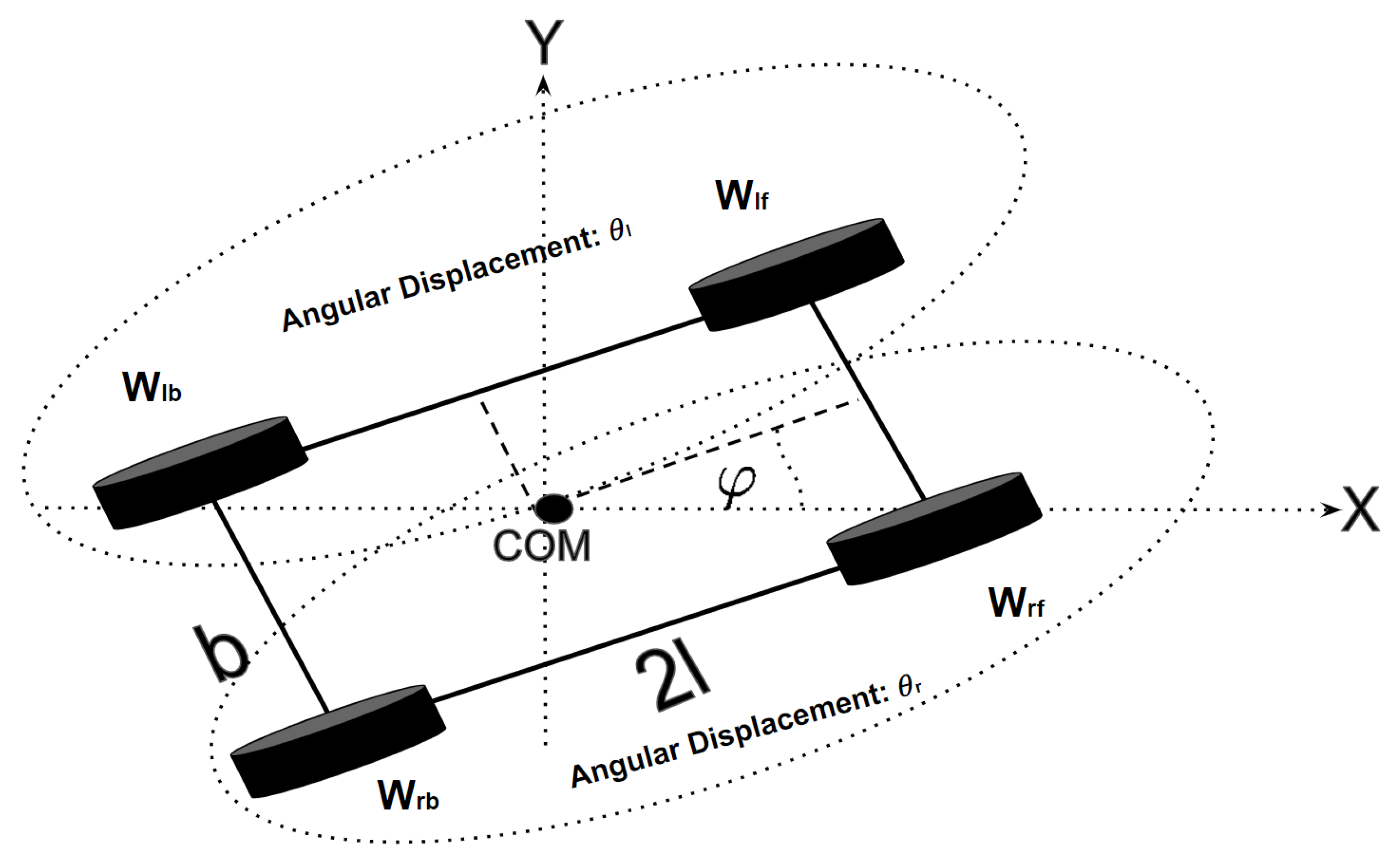
Dynamics of Panthera [57] is described by the following equations:
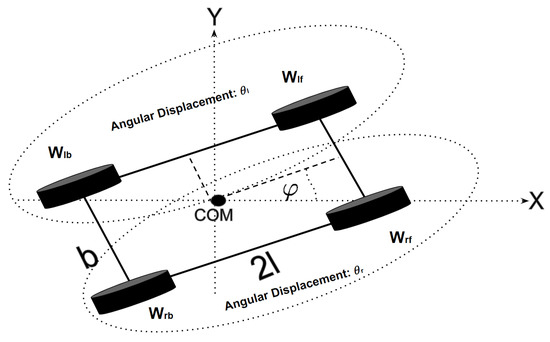
Figure A1.
Schematic of the base of PANTHERA.
Figure A1.
Schematic of the base of PANTHERA.
References
- Hargadine, C.S. Mobile Robot Navigation and Obstacle Avoidance in Unstructured Outdoor Environments; Technical Report; Naval Postgraduate School: Monterey, CA, USA, 2017. [Google Scholar]
- Pandey, A.; Pandey, S.; Parhi, D. Mobile robot navigation and obstacle avoidance techniques: A review. Int. Rob. Auto. J. 2017, 2, 00022. [Google Scholar] [CrossRef]
- Borenstein, J.; Koren, Y. Real-time obstacle avoidance for fast mobile robots. IEEE Trans. Syst. Man. Cybern. 1989, 19, 1179–1187. [Google Scholar] [CrossRef]
- Mingnuo. Mingnuo Clean. 2021. Available online: http://www.mingnuoclean.com/index.html (accessed on 30 August 2022).
- HuaXinTech. Ride on Auto Sweeper Machine Vacuum. 2021. Available online: https://www.yangziindustry.com/Products/ (accessed on 19 May 2022).
- Johnston. Johnston Sweepers. 2021. Available online: https://www.buchermunicipal.com/int/johnston-sweepers-0 (accessed on 30 August 2022).
- Widyotriatmo, A.; Hong, B.; Hong, K.S. Predictive navigation of an autonomous vehicle with nonholonomic and minimum turning radius constraints. J. Mech. Sci. Technol. 2009, 23, 381–388. [Google Scholar] [CrossRef]
- Antonelli, D.; Nesi, L.; Pepe, G.; Carcaterra, A. A novel approach in Optimal trajectory identification for Autonomous driving in racetrack. In Proceedings of the 2019 18th European Control Conference (ECC), Naples, Italy, 25–28 June 2019; pp. 3267–3272. [Google Scholar]
- Pérez-Morales, D.; Kermorgant, O.; Domínguez-Quijada, S.; Martinet, P. Multi-Sensor-Based Predictive Control for Autonomous Parking in Presence of Pedestrians. In Proceedings of the 2020 16th International Conference on Control, Automation, Robotics and Vision (ICARCV), Shenzhen, China, 13–15 December 2020; pp. 406–413. [Google Scholar]
- Tan, N.; Hayat, A.A.; Elara, M.R.; Wood, K.L. A framework for taxonomy and evaluation of self-reconfigurable robotic systems. IEEE Access 2020, 8, 13969–13986. [Google Scholar] [CrossRef]
- Prabakaran, V.; Elara, M.R.; Pathmakumar, T.; Nansai, S. Floor cleaning robot with reconfigurable mechanism. Autom. Constr. 2018, 91, 155–165. [Google Scholar] [CrossRef]
- Hayat, A.A.; Karthikeyan, P.; Vega-Heredia, M.; Elara, M.R. Modeling and assessing of self-reconfigurable cleaning robot hTetro based on energy consumption. Energies 2019, 12, 4112. [Google Scholar] [CrossRef]
- Cheng, K.P.; Mohan, R.E.; Nhan, N.H.K.; Le, A.V. Multi-objective genetic algorithm-based autonomous path planning for hinged-tetro reconfigurable tiling robot. IEEE Access 2020, 8, 121267–121284. [Google Scholar] [CrossRef]
- Lakshmanan, A.K.; Mohan, R.E.; Ramalingam, B.; Le, A.V.; Veerajagadeshwar, P.; Tiwari, K.; Ilyas, M. Complete coverage path planning using reinforcement learning for tetromino based cleaning and maintenance robot. Autom. Constr. 2020, 112, 103078. [Google Scholar] [CrossRef]
- Muthugala, M.V.J.; Samarakoon, S.B.P.; Elara, M.R. Toward energy-efficient online Complete Coverage Path Planning of a ship hull maintenance robot based on Glasius Bio-inspired Neural Network. Expert Syst. Appl. 2021, 187, 115940. [Google Scholar] [CrossRef]
- Le, A.V.; Veerajagadheswar, P.; Kyaw, P.T.; Muthugala, M.V.J.; Elara, M.R.; Kuma, M.; Nhan, N.H.K. Towards optimal hydro-blasting in reconfigurable climbing system for corroded ship hull cleaning and maintenance. Expert Syst. Appl. 2021, 170, 114519. [Google Scholar] [CrossRef]
- Le, A.V.; Parween, R.; Elara Mohan, R.; Nhan, N.H.K.; Enjikalayil Abdulkader, R. Optimization complete area coverage by reconfigurable hTrihex tiling robot. Sensors 2020, 20, 3170. [Google Scholar] [CrossRef]
- Le, A.V.; Veerajagadheswar, P.; Thiha Kyaw, P.; Elara, M.R.; Nhan, N.H.K. Coverage Path Planning Using Reinforcement Learning-Based TSP for hTetran—A Polyabolo-Inspired Self-Reconfigurable Tiling Robot. Sensors 2021, 21, 2577. [Google Scholar] [CrossRef]
- Le, A.V.; Nhan, N.H.K.; Mohan, R.E. Evolutionary Algorithm-Based Complete Coverage Path Planning for Tetriamond Tiling Robots. Sensors 2020, 20, 445. [Google Scholar] [CrossRef]
- Vega-Heredia, M.; Mohan, R.E.; Wen, T.Y.; Siti’Aisyah, J.; Vengadesh, A.; Ghanta, S.; Vinu, S. Design and modelling of a modular window cleaning robot. Autom. Constr. 2019, 103, 268–278. [Google Scholar] [CrossRef]
- Tun, T.T.; Huang, L.; Mohan, R.E.; Matthew, S.G.H. Four-wheel steering and driving mechanism for a reconfigurable floor cleaning robot. Autom. Constr. 2019, 106, 102796. [Google Scholar] [CrossRef]
- Shi, Y.; Elara, M.R.; Le, A.V.; Prabakaran, V.; Wood, K.L. Path tracking control of self-reconfigurable robot hTetro with four differential drive units. IEEE Robot. Autom. Lett. 2020, 5, 3998–4005. [Google Scholar] [CrossRef]
- Hayat, A.A.; Parween, R.; Elara, M.R.; Parsuraman, K.; Kandasamy, P.S. Panthera: Design of a Reconfigurable Pavement Sweeping Robot. In Proceedings of the International Conference on Robotics and Automation (ICRA), Montreal, QC, Canada, 20–24 May 2019; pp. 7346–7352. [Google Scholar]
- Yi, L.; Gómez, B.F.; Ramalingam, B.; Rayguru, M.M.; Elara, M.R.; Hayat, A.A. Self-reconfigurable robot vision pipeline for safer adaptation to varying pavements width and surface conditions. Sci. Rep. 2022, 12, 14557. [Google Scholar] [CrossRef]
- Yim, S. Comparison among active front, front independent, 4-wheel and 4-wheel independent steering systems for vehicle stability control. Electronics 2020, 9, 798. [Google Scholar] [CrossRef]
- Qiu, H.; Liang, S.; Qi, Z.; Qin, H. A novel design of an in-situ steering for a 4-wheel independent steering in a 4-in-wheel-motor Drive Electric Vehicle. In Proceedings of the 2012 19th International Conference on Mechatronics and Machine Vision in Practice (M2VIP), Auckland, New Zealand, 28–30 November 2012; pp. 42–45. [Google Scholar]
- Hang, P.; Chen, X. Towards Autonomous Driving: Review and Perspectives on Configuration and Control of Four-Wheel Independent Drive/Steering Electric Vehicles. Actuators 2021, 10, 184. [Google Scholar] [CrossRef]
- Nah, J.; Yim, S. Vehicle stability control with four-wheel independent braking, drive and steering on in-wheel motor-driven electric vehicles. Electronics 2020, 9, 1934. [Google Scholar] [CrossRef]
- Hayat, A.A.; Yi, L.; Kalimuthu, M.; Elara, M.; Wood, K.L. Reconfigurable robotic system design with application to cleaning and maintenance. J. Mech. Des. 2022, 144, 063305. [Google Scholar] [CrossRef]
- Manimuthu, M.; Hayat, A.A.; Elara, M.R.; Wood, K. Transformation design Principles as enablers for designing Reconfigurable Robots. In Proceedings of the International Design Engineering Technical Conferences and Computers and Information in Engineering Conference, Virtual, 17 August 2021; pp. 1–12. [Google Scholar]
- Ottaviano, E.; Rea, P. Design and operation of a 2-DOF leg–wheel hybrid robot. Robotica 2013, 31, 1319–1325. [Google Scholar] [CrossRef]
- Ma, F.; Shi, J.; Yang, Y.; Li, J.; Dai, K. ACK-MSCKF: Tightly-Coupled Ackermann Multi-State Constraint Kalman Filter for Autonomous Vehicle Localization. Sensors 2019, 19, 4816. [Google Scholar] [CrossRef]
- Din, Z.M.U.; Razzaq, W.; Arif, U.; Ahmad, W.; Muhammad, W. Real time Ackerman steering angle control for self-driving car autonomous navigation. In Proceedings of the 2019 4th International Conference on Emerging Trends in Engineering, Sciences and Technology (ICEEST), Karachi, Pakistan, 10–11 December 2019; pp. 1–4. [Google Scholar]
- Shojaei, K.; Shahri, A.M.; Tarakameh, A.; Tabibian, B. Adaptive trajectory tracking control of a differential drive wheeled mobile robot. Robotica 2011, 29, 391–402. [Google Scholar] [CrossRef]
- Shih, C.L.; Lin, L.C. Trajectory Planning and Tracking Control of a Differential-Drive Mobile Robot in a Picture Drawing Application. Robotics 2017, 6, 17. [Google Scholar] [CrossRef]
- Malu, S.K.; Majumdar, J. Kinematics, localization and control of differential drive mobile robot. Glob. J. Res. Eng. 2014, 14, 1–9. [Google Scholar]
- Salem, F.A. Dynamic and kinematic models and control for differential drive mobile robots. Int. J. Curr. Eng. Technol. 2013, 3, 253–263. [Google Scholar]
- Jun, J.Y.; Hua, M.D.; Benamar, F. A trajectory tracking control design for a skid-steering mobile robot by adapting its desired instantaneous center of rotation. In Proceedings of the 53rd IEEE Conference on Decision and Control, Los Angeles, CA, USA, 15–17 December 2014; pp. 4554–4559. [Google Scholar]
- Xu, H.; Xue, K.; Wang, P.; Marie, B.S.; Wei, R.; Jin, B. Maneuver Control and Kinematical Energy Analysis of a Robot Based on Instantaneous Center of Rotation. In Proceedings of the 2006 1ST IEEE International Conference on E-Learning in Industrial Electronics, Hammamet, Tunisia, 18–20 December 2006; pp. 101–106. [Google Scholar]
- Xu, H.; da Wang, W.; Sidibe, M.B. Maneuver Algorithm for Mobile Robot with Four Steered Propulsive Wheels. In Proceedings of the 6th WSEAS International Conference on Signal Processing, Robotics and Automation, Corfu Island, Greece, 16–19 February 2007; pp. 151–157. [Google Scholar]
- Galceran, E.; Carreras, M. A survey on coverage path planning for robotics. Robot. Auton. Syst. 2013, 61, 1258–1276. [Google Scholar] [CrossRef]
- Choset, H.; Pignon, P. Coverage Path Planning: The Boustrophedon Cellular Decomposition. In Field and Service Robotics; Zelinsky, A., Ed.; Springer: London, UK, 1998; pp. 203–209. [Google Scholar]
- Yan, J.; Diakité, A.A.; Zlatanova, S.; Aleksandrov, M. Finding outdoor boundaries for 3D space-based navigation. Trans. GIS 2020, 24, 371–389. [Google Scholar] [CrossRef]
- Chen, Q.; Xie, Y.; Guo, S.; Bai, J.; Shu, Q. Sensing system of environmental perception technologies for driverless vehicle: A review of state of the art and challenges. Sens. Actuators Phys. 2021, 319, 112566. [Google Scholar] [CrossRef]
- Dai, P.; Taghia, J.; Lam, S.; Katupitiya, J. Integration of Sliding Mode Based Steering Control and PSO Based Drive Force Control for a 4WS4WD Vehicle; Springer: Berlin/Heidelberg, Germany, 2018; Volume 42, pp. 1573–7527. [Google Scholar]
- Huang, S.J.; Shiao, Y.W. 2D path control of four omni wheels mobile platform with compass and gyroscope sensors. Sens. Actuators A Phys. 2015, 234, 302–310. [Google Scholar] [CrossRef]
- Fox, D.; Burgard, W.; Thrun, S. The dynamic window approach to collision avoidance. IEEE Robot. Autom. Mag. 1997, 4, 23–33. [Google Scholar] [CrossRef] [Green Version]
- Limpert, N.; Schiffer, S.; Ferrein, A. A local planner for Ackermann-driven vehicles in ROS SBPL. In Proceedings of the 2015 Pattern Recognition Association of South Africa and Robotics and Mechatronics International Conference (PRASA-RobMech), Port Elizabeth, South Africa, 26–27 November 2015; pp. 172–177. [Google Scholar]
- Missura, M.; Bennewitz, M. Predictive collision avoidance for the dynamic window approach. In Proceedings of the 2019 International Conference on Robotics and Automation (ICRA), Montreal, QC, Canada, 20–24 May 2019; pp. 8620–8626. [Google Scholar]
- Le, A.V.; Prabakaran, V.; Sivanantham, V.; Mohan, R.E. Modified a-star algorithm for efficient coverage path planning in tetris inspired self-reconfigurable robot with integrated laser sensor. Sensors 2018, 18, 2585. [Google Scholar] [CrossRef]
- Khan, A.R.; Khan, A.T.; Salik, M.; Bakhsh, S. An Optimally Configured HP-GRU Model Using Hyperband for the Control of Wall Following Robot. Int. J. Robot. Control Syst. 2021, 1, 66–74. [Google Scholar] [CrossRef]
- Madi, S.; Baba-Ali, R. Classification techniques for wall-following robot navigation: A comparative study. In Proceedings of the International Conference on Advanced Intelligent Systems and Informatics, Cairo, Egypt, 1–3 September 2018; pp. 98–107. [Google Scholar]
- Suwoyo, H.; Tian, Y.; Deng, C.; Adriansyah, A. Improving a wall-following robot performance with a PID-genetic algorithm controller. In Proceedings of the 2018 5th International Conference on Electrical Engineering, Computer Science and Informatics (EECSI), Malang, Indonesia, 16–18 October 2018; pp. 314–318. [Google Scholar]
- Carelli, R.; Freire, E.O. Corridor navigation and wall-following stable control for sonar-based mobile robots. Robot. Auton. Syst. 2003, 45, 235–247. [Google Scholar] [CrossRef]
- Siegwart, R.; Nourbakhsh, I.R.; Scaramuzza, D. Introduction to Autonomous Mobile Robots; MIT Press: Cambridge, MA, USA, 2011. [Google Scholar]
- Yi, L.; Le, A.V.; Ramalingam, B.; Hayat, A.A.; Elara, M.R.; Minh, T.H.Q.; Gómez, B.F.; Wen, L.K. Locomotion with Pedestrian Aware from Perception Sensor by Pavement Sweeping Reconfigurable Robot. Sensors 2021, 21, 1745. [Google Scholar] [CrossRef]
- Rayguru, M.M.; Mohan, R.E.; Parween, R.; Yi, L.; Le, A.V.; Roy, S. An Output Feedback Based Robust Saturated Controller Design for Pavement Sweeping Self-Reconfigurable Robot. IEEE/ASME Trans. Mechatronics 2021, 26, 1236–1247. [Google Scholar] [CrossRef]
- Roy, S.; Nandy, S.; Ray, R.; Shome, S.N. Robust path tracking control of nonholonomic wheeled mobile robot: Experimental validation. Int. J. Control. Autom. Syst. 2015, 13, 897–905. [Google Scholar] [CrossRef]


Publisher’s Note: MDPI stays neutral with regard to jurisdictional claims in published maps and institutional affiliations. |
© 2022 by the authors. Licensee MDPI, Basel, Switzerland. This article is an open access article distributed under the terms and conditions of the Creative Commons Attribution (CC BY) license (https://creativecommons.org/licenses/by/4.0/).