1. Introduction
Mobile communication is an ongoing trend in information exchange and distribution. Mobile traffic grows exponentially. Overall, IP traffic is expected to grow to 396 EB per month by 2022 [
1]. Numerous technologies have been introduced to support higher data rates for a given spectrum along with the evolution of mobile communication. Nowadays, the data rate can be up to 1G bps for 4G (Long-Term Evolution—Advanced, LTE-A) networks [
2]. There has been a significant improvement in spectrum efficiency. However, faced with ever-increasing traffic demand, we keep pursuing new measures for even better spectrum efficiency. In addition to new modulation technology, new paradigms, such as Dense Small Cell Network and Device-to-Device (D2D) Communication, offer promising solutions to the challenge.
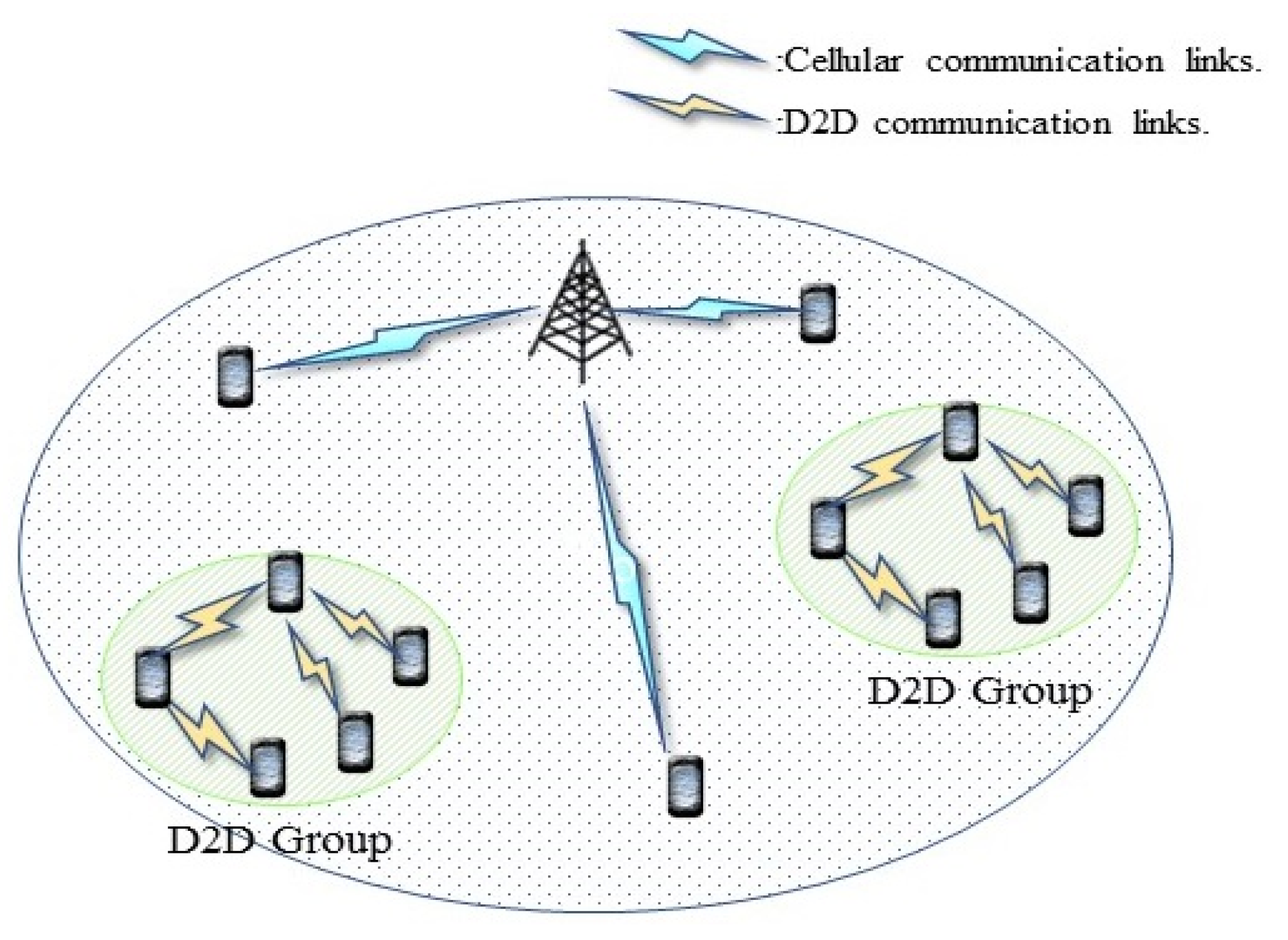
Figure 1 gives an intended environment for the D2D communication mode addressed in 3GPP’s Release 12 [
2]. Users in proximity form a communication group. It is not uncommon for communication group members to share a common interest in particular digital content [
3]. If a group member already possesses a particular content, other members can download the content from the possessing member rather than from the Internet via a base station. The D2D communication mode is designed for direct communications with nearby User Equipment (UE) without the intervention of base stations. It implies a higher data rate, a better spectrum efficiency, and a lower base station loading.
The idea of D2D communication brings about 3GPP ushering in Proximity Service (ProSe). There are different approaches to the implementation of D2D communication, including Wi-Fi Direct, Bluetooth, and LTE Direct. We focus on D2D communication with LTE Direct in this paper.
Figure 2 illustrates the difference between regular cellular communication and LTE D2D communication. With LTE D2D, UEs can communicate with each other directly. The base station is only responsible for the coordination. LTE D2D has great potential for many reasons, including lower base station loading, lower power consumption, improved resource utilization, reduced delay, and improved QoS (Quality of Service) support [
4].
There are essential issues in LTE D2D, such as device discovery, mode selection, resource allocation, and group communication. Device discovery is the process of finding matched devices. There are two different device discovery approaches, distributed and centralized approaches [
5]. UEs initiate the former, and the latter is controlled by the Mobility Management Entity (MME), the Packet Data Network Gateway (PDN-GW), and the base station. LTE has two different operation modes, namely cellular mode and D2D mode. The D2D mode is further classified into the dedicated mode and reuse mode. These two modes differ in the way resource blocks are allocated. Cellular UEs and D2D UEs in reused mode share the same resource blocks. On the other hand, in dedicated mode, UEs use resource blocks exclusively assigned to them. Which mode should be in use leads to the resource allocation problem, which is a tradeoff between resource utilization and interference.
Intra-group communication (group communication for short) is the primary scenario in this study. As shown in
Figure 1, nearby UEs can form a group and are capable of group communication with each other. A UE in a group can access content possessed by other group members via group communication. Genuinely, group communication can improve the overall efficiency of the entire network environment [
6]. There may exist a group leader in each group. A group leader will be in charge of the group resources’ bookkeeping and coordination with the base station [
7]. The presence of group leaders further reduces the loading of base stations. The hop-count in data transmission also affects the efficiency of group communication. Several alternative paths may exist from a source UE to a destination UE. A single-hop, long-distance transmission link may experience low bandwidth due to a low Signal-to-Noise Ratio (SNR). On the other hand, multi-hop, short-distance transmission links may suffer from longer delays [
8]. Therefore, finding the best route between UEs in a group is a critical issue that deserves further investigation.
This study contributes to the group routing problem, that is, finding the best path from a source UE to a destination UE with consideration of both lowering the delay and raising the throughput. More specifically, in this study
A utility function of D2D paths is defined considering both delay and throughput.
Finding the best path is formally formulated as an NP-hard problem.
A Bidirectional and InCremental A-star (BICA*) algorithm incorporating the concept of bidirectional search and lifelong planning is developed to tackle the NP-hard search problem.
A series of simulations are conducted to verify the feasibility and effectiveness of the proposed approach.
The rest of this paper is organized as follows. Previous works on D2D communication and related technology are briefly reviewed in
Section 2. We define the network model and formulate the route planning as an NP-hard optimization problem in
Section 3. Then, our Bidirectional and InCremental A-star algorithm (BICA*) for group communication is presented in
Section 4 with an in-depth explanation and discussion. A series of simulations validating our approach’s feasibility and effectiveness is presented in
Section 5. Finally, some conclusions are drawn in
Section 6.
2. Related Works and Technology
Numerous works have been devoted to D2D communications from different perspectives. Adnan and Zukarnain [
9] address issues, solutions, and challenges in D2D communication in 5G environments. Gismalla et al. [
10] provide a comprehensive survey on D2D communication, featuring basic concepts, target applications, potential challenges, and future directions. Among other issues, routing in D2D networks has received considerable attention due to its important role in system performance. In [
11], Shaikh and Wismüller present an excellent review of recent advances in D2D routing technology. They classify use cases into three classes: multi-hop D2D routing, multi-hop D2I/I2D routing, and ad hoc routing. Focusing on multi-hop D2D routing, our work differs from others in that we formulate the overall route planning problem as an NP-hard optimization problem and approach the real-time routing problem using an integrated bidirectional and lifelong-planning A* algorithm. Our approach furnishes valuable insight into the D2D routing problem and develops a method from a new perspective by incorporating classical wisdom.
Studies [
12,
13,
14] show that group communication has become a common form of mobile networking. Mobile users in proximity form a communication group partaking in the same interest in some digital content. Once a user has downloaded a particular content, the other users can download the content from the user via D2D group communication without the need for cellular communication. These observations imply that an efficient D2D group communication scheme, as the focus of this study, is essential for future mobile networking.
A number of works contributed to D2D group communication. An early work [
15] analyzes the performance difference between multi-hop and single-hop transmission. However, the path selection problem was not properly addressed. In [
16], message forwarding is completed by broadcasting. By doing so, the number of control messages can be significantly reduced. However, it can also introduce a broadcast storm problem. Our approach adopts a unicast scheme. We define the cost for individual transmission links and then find a path with the least cost. In [
17], a UE with less interference is selected as the relay UE. The approach may not have the optimal outcome, since the systemic relationship among the sender, relay, and receiver is not accounted for. The study in [
18] takes into consideration the location of UEs. The coverage of a base station is partitioned into five regions. The region close to the base station is excluded from the selection due to severe interference. Their approach prefers a relay located in the same region a sender resides in. Both [
17,
18] had achieved their objectives. Nevertheless, both schemes did not consider that a single-hop relay may fail to fulfill the forwarding need, so a multiple-hop relay is required to complete the forwarding. A multi-hop relay path is needed to accomplish the transmission task. Finding a relaying path (a route) with less cost for D2D group communication is the core issue of D2D communication [
19,
20,
21].
To facilitate multi-hop D2D communications in 5G networks, a framework for virtual mesh networking is created in [
19]. Base stations gather terminal link and topology data before creating a virtual mesh network among the terminals in accordance. The virtual mesh routing method, which also considers terminal mobility and connection failure, then chooses the routing path for end-to-end communications. In order to provide D2D content sharing with multi-hop communication capabilities, Zhang et al. [
20] suggest a game theoretic strategy. The routing and price graphs are produced by modeling a Nash bargaining game with a subset of players, where a novel incentive mechanism is used to encourage cooperation. Ahmed modifies the standard DSR (Dynamic Source Routing) protocol in [
21] to allow for quick routing decisions. The suggested protocol saves the control messages of devices during the route-finding process by having a minimal overhead compared to the standard DSR in terms of the number of control messages in the D2D communication. This study regards the D2D routing problem as the shortest (with the least delay and the maximal throughput) path problem and tackles it with a Bidirectional, InCremental A* algorithm for responsiveness.
Social awareness is another discussion-provoking issue. Certain incentives are presumed such that an individual UE will be willing to forward packets to others at the cost of increased power consumption. Ometov et al. [
22] have an in-depth discussion on this matter. This study assumes a social incentives framework. That is, UEs in the same group have a strong social bond and are willing to help each other. Typical examples include field trips to schools, social engagement events of organizations, and so forth.
There are two well-known routing algorithms for network routing: namely, the link-state algorithm and the distance-vector algorithm [
23]. With link-state routing, every router exchanges its link status information with all other routers in the autonomous system. The Dijkstra algorithm is then employed to find out the shortest paths. In distance-vector routing, each router exchanges link status information with its direct neighbors. The topology information will gradually be propagated to all routers in an autonomous system. This study adopts an approach enlightened by link-state routing. As we shall see in the later discussion, the route planning for D2D group communication can be formulated as an NP-hard problem. Instead of utilizing the Dijkstra algorithm directly, we render the algorithm in the routing plan by comprising two modified A* algorithms, namely Bidirectional Search A* algorithm (BSA*) [
24] and Lifelong Planning A* algorithm (LPA*) [
25].
The A* algorithm incorporates the idea of the Best-First Search and Dijkstra algorithm. During the search, the A* search expands an intermediate node,
, with a minimal cost, as follows:
where
is the actual cost from the start node to node
;
is a heuristically estimated cost from node
to the goal node. The A* algorithm was pioneered by Peter Hart, Nils Nilsson, and Bertram Raphael in 1968 [
26], which ensures an optimal path if
is less or equal to the real cost from node n to the goal node. After that, a long list of variants with different appeals had been proposed, including Beam Search A* [
27], Iterative Deeping A* [
28], Dynamic Weighting A* [
29], and Jump Point Search A* [
30].
Among all variants, Bidirectional Search A* (BSA*) and Lifelong Planning A* (LPA*) draw our attention to their potential in our framework. As its name implied, BSA* constructs search trees from both the start and the goal nodes in opposite directions. The search terminates when the search trees intersect in reverse directions. It is evident that BSA* is capable of speeding up the search process. LPA* is an incremental version of the A* algorithm, which would adapt to changes in the search tree without recalculating the entire search tree. Upon the detection of topological change, it merely updates the from the previous search without reconstructing the entire search tree. This feature endows LPA* with the ability to quick reaction in response to topological change.
A review of these works leads to the architectural design of our routing scheme for D2D group communication. The path selection problem can be formulated as an optimization problem with delay and throughput as its cost function. The optimization problem is then resolved by an advanced BICA* algorithm consolidating the concept of bidirectional search and lifelong planning.
3. Problem Formulation
Figure 3 shows a typical scenario for the mobile networking environment we intend. There is a macro-cell base station and a number of UE groups. Each UE device is equipped with a storage device. UEs in the same group share the same interest in digital content and are willing to share them with group members. Each group has a group header that keeps track of the availability of digital content in the group. UE can consult the header for the availability of a particular content whenever needed.
There are four possible situations when a UE requests a particular content, as follows:
No one in the group possesses the content.
The content is possessed by another member of the same group, and delivery of the content via D2D group communication is within the delay constraint.
Another group member possesses the content. However, delivery of the content via D2D group communication exceeds the delay constraint.
The content is possessed by another group member. However, neither delivery of the content via D2D group communication nor cellular communication can meet the delay constraint.
For situations 1 and 3, the content will be downloaded from the core network via cellular communication. For situations 2 and 4, our approach will play its role and determine the best route for the D2D group communication.
We assume that within one macro-cell base station, there are
groups,
contents, and
UEs, where
and
To evaluate the preference of a path, we define a utility function considering both throughput and delay. The utility for the path with which UE
downloads content
from UE
is defined as follows:
where
and
are the utility values from the normalization of delay and throughput, respectively;
and
are weighting coefficients for delay and throughput, respectively;
and
. We prefer a path with less delay, therefore, there is a
1 factor for
in Equation (2).
Delay and throughput are different measurement benchmarks. Normalization is required for the utility function to be meaningful. T-score, as follows, is used in our normalization:
The utilities for delay and throughput can then be defined as follows:
where
and
are the delay and the throughput of the path with which UE
downloads content
from UE
;
and
are the mean delay and mean throughput;
and
are the standard deviations of delay and throughput.
We are interested in the route planning for D2D group communication in the environment, that is, the maximization of the overall utility of the entire environment. This problem can be formulated as a constrained optimization problem:
s.t.
where
is the delay constraint for content
;
are indicator functions.
is 1 if the Signal to Interference plus Noise Ratio (SINR) of the path from UE
to UE
meets the minimal requirement of content
, and it is 0 otherwise.
is 1 if UE
downloads content
from UE
with a satisfied SINR ratio (
, and it is 0 otherwise.
Equations (7) and (8) indicate that content will pass through UE and UE at least once. Equation (9) is to ensure that the SINR of the path from UE to UE meets the minimal requirement of content . Equation (10) implies the conservation of flow. UE is an intermediate node on the path between UE and UE . Any content entering UE will be forwarded toward its destination. Equation (11) shows that the time UE takes in downloading content from UE must meet the delay constraint of content .
The routing problem for group communication defined in Equation (6) is an NP-hard problem. It is equivalent to the Open Vehicle Routing Problem (OVRP), which had been proved to be an NP-hard problem. OVRP originated from the Vehicle Routing Problem (VRP) introduced by G. B. Dantzig and J. H. Ramser in 1959 [
31]. The difference for OVRP is that vehicles need not return to the service center after delivery. In a VRP, there are several customers, each having merchandise needs. A distribution center serves customers with a vehicle fleet. The object is to plan the routes for vehicles with minimal total cost. An OVRP can be formulated as follows:
s.t.
where
and
are indices for customers;
is the index for vehicles;
is the cost it takes for vehicle
to travel from customer
to customer
.
and
are indicator functions.
is 1 if vehicle
takes the path from customer
to customer
, and it is 0 otherwise.
is 1 if vehicle
can pass through customer
and customer
, and it is 0 otherwise.
is the capacity of vehicle
.
is the weight of customer
’s merchandise on vehicle
.
Equations (17) and (18) indicate that vehicle will pass through customer and customer at least once. Equation (19) is to ensure that the vehicle serving customer and customer must be valid. Equation (20) implies the conservation of flow. Equation (7.521) says the total weight of all merchandises on vehicular cannot exceed the capacity of vehicle .
The maximization problem in Equation (6) can be easily transformed into a minimization problem by multiplying the right side with (
1).
Content in Equation (6) is corresponding to vehicle in Equation (16). Equations (9) and (19) can be viewed as the counterpart of each other in these two problems. The delay constraint in Equation (6) is equivalent to the capacity constraint in Equation (19). That is, the two problems are equivalent, and our problem also belongs to the class of NP-hard problems.
4. D2D Group Communication Scheme with Bidirectional and InCremental A-Star (BICA*) Routing
A path can be established if the SINR threshold constraint is satisfied. For a multi-hop path, the overall data rate is determined by the hop with the worst SINR. For example, we consider a two-hop path:
where
is the SINR from UE
to UE
;
is the SINR from UE
to relay
;
is the SINR from relay
to UE
;
and
are transmission powers of UE
and relay r;
is the path loss from UE
to relay
;
is the path loss from relay r to UE
;
and
are interference powers experienced by UE
and relay
;
is the noise.
should be larger than the SINR threshold,
.
The
in Equation (4) consists of three parts: propagation delay, transmission delay, and processing delay. The
can be a UE or a base station. We consider first that the case
is a UE.
The propagation delay
can be evaluated according to:
where
is the length of an individual hop on the path from UE
to UE
;
is the speed of the radio wave.
should be small than
, which is the maximal transmission range for D2D communication.
can then be evaluated according to:
where
is the packet size;
is the number of transmissions;
is the bandwidth.
The processing delay,
, depends on the computing power of a node. According to [
32], the typical measurement of
is around 1 ms, and it can be neglected in most applications.
We now consider the case UE
downloading content
from the base station. The reasoning and derivation are similar to the previous case.
where
is the distance between UE
and the base station;
is the SINR from UE
i to the base station.
As for the evaluation of throughput,
, in Equation (5), we follow the Shannon capacity equation, as shown in Equation (16):
4.1. Control Flow of D2D Group Communication
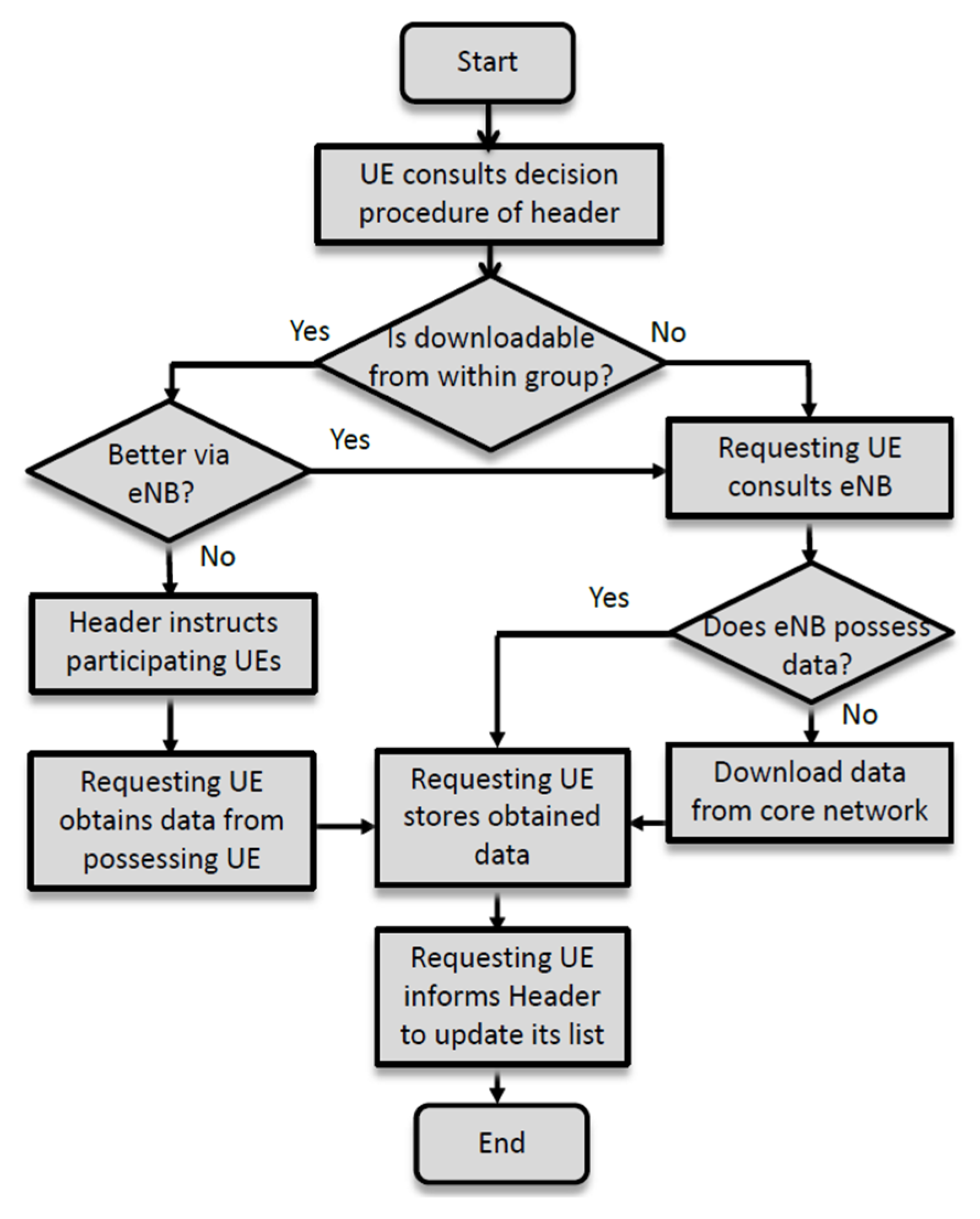
When a UE requests a particular content, the proposed D2D group communication scheme will be invoked to find the best path to the content with maximal utility. The control flow for the proposed routing scheme for D2D group communication is given in
Figure 4.
A member UE consults its group header for the availability of certain content. The header will execute a decision procedure, which will be discussed in the next subsection, to decide whether the content should be downloaded from the possessing UE or the core network. If it is preferred to download the content from the possessing UE, the header will inform the requesting UE, relay UEs, and possess UE to conduct the content delivery. After the completion of the delivery, the requesting UE may retain the content in its storage and report to the group header. A signaling diagram for such a D2D intra-group communication is given in
Figure 5. On the other hand, if no one in the group possesses the content or downloading the content via D2D intra-group communication fails to meet the delay constraint, the group header will instruct the requesting UE to download the content from the eNB if the eNB holds onto the requested content or the core network if the eNB cannot provide the content. The signaling of downloading data from the eNB is straightforward and omitted here. The signaling diagram is given in
Figure 6 [
33] for downloading content from the core network.
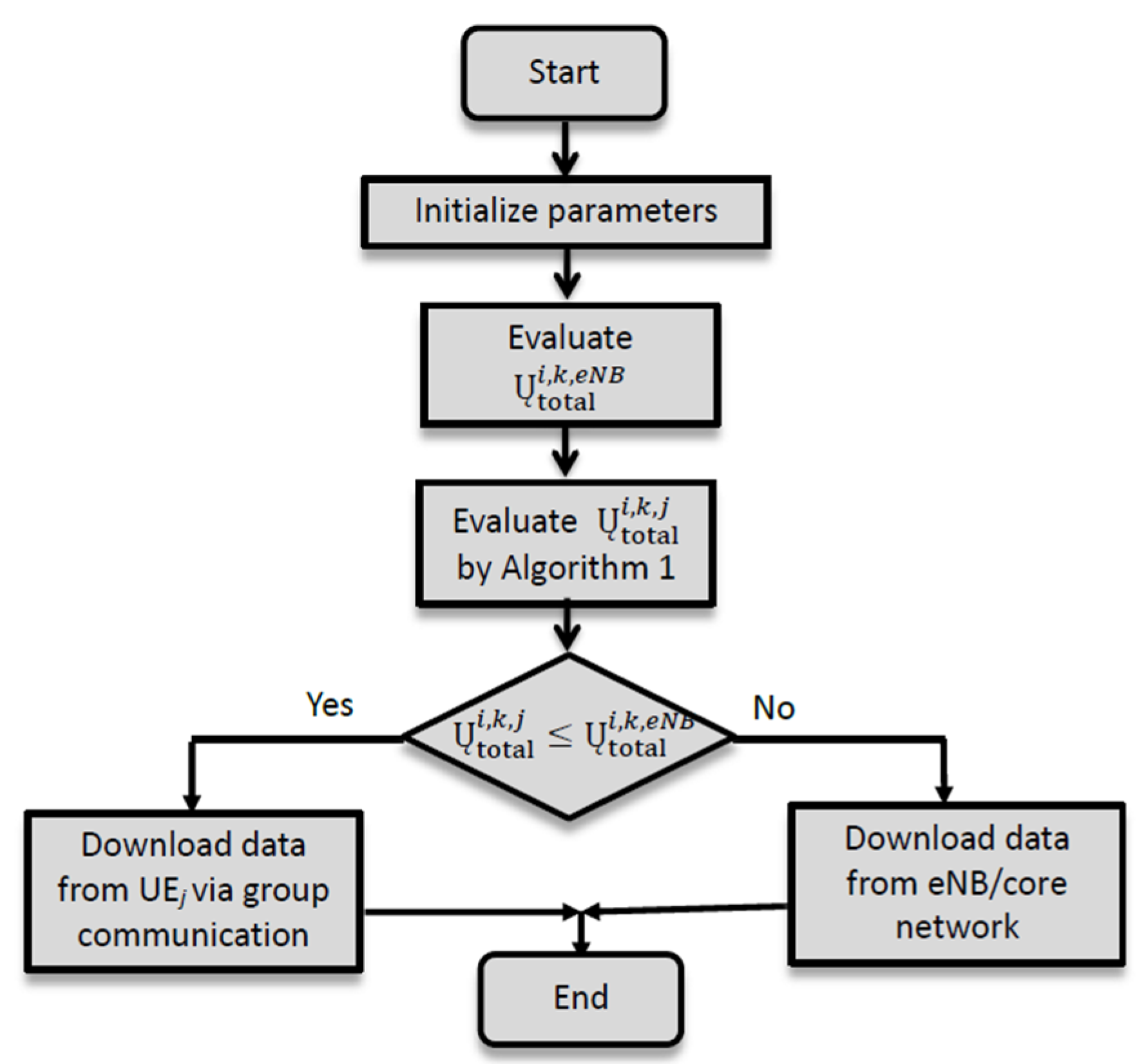
Upon receiving a request for content
from UE
, the group header has to decide whether the content should be downloaded from the base station or from possessing UE
. The group header answers this question by the evaluation and comparison of
and
, and it follows the decision procedure in
Figure 7. The evaluation of
is straightforward, while the evaluation of
is much more involved. The path selection algorithm, discussed in the next subsection, will be invoked for the evaluation of
. The path selection algorithm is designed to determine the best path connecting UE
and UE
with maximal utility. The group header will instruct involved parties to download content
from the base station if
, and download content
from UE
otherwise.
4.2. Path Selection Algorithm
The path selection algorithm discussed in this subsection is the core component of the proposed scheme. It answers the question of whether content sharing via D2D group communication is preferred over downloading content from the core network. It constructs a path connecting UE and UE with the maximal utility and reports the obtained utility value to the group header for its decision making.
The topology of a UE group can be represented by an undirected graph with UEs as nodes and links as edges. Search algorithms, such as the Dijkstra algorithm, can then be employed to find the shortest path between two given nodes. However, an exhaustive examination of all nodes could be time-consuming. Therefore, we adopt a Bidirectional, inCremental A* (BICA*) algorithm in our routing scheme, as shown in Algorithm 1. Radio links would be, in most situations, symmetric, so it is feasible for the bidirectional A* algorithm to construct the search trees from both sides, with which the search speed can be doubled. The lifelong-planning A* algorithm is an incremental version of the A* algorithm. This feature makes it well-suited for dealing with topology change, which is quite often in mobile networking. It repeatedly finds the shortest paths from a given start node to a destination node, while the edge costs of a graph change or vertices are added or deleted. Its first search is the same as that of a standard A* that breaks ties in favor of nodes with smaller -values. However, subsequent searches are potentially faster because they reuse those parts of the previous search tree that are not changed. The symbols used in Algorithm 1 are defined as follows:
: Set of all nodes.
: The utility from node to node .
: The actual utility from the start node to node
. It can be evaluated according to
: The actual utility from the start node to node
is evaluated according to the right-hand side rule [
25]. It differs from
in the timing of evaluation. In the algorithm,
will be reevaluated and compared with previous
. A mismatch is an indication of topological change. It can be evaluated according to
: The estimated utility from node to the goal node. We use the real distance from node to the goal node multiplied by .
is the key values at node . It is used to decide which node in the priority queue should be expanded first. The comparison is made in lexicographical order. That is, we compare first. If two nodes have the same , we then compare . The philosophy behind the lexicographical order comparison is that when two nodes in the queue have the same value, we prefer the node with a higher , which is supposed to be a more reliable estimation of the remaining route.
: Priority queue of nodes sorted according to their ’s.
In the Bidirectional, InCremental A* path selection algorithm, BICA*, in Algorithm 1, variables are initialized in Lines 1 to 8. Inputs Start and Goal are the start node and the goal node, respectively. Set
consists of all nodes. Since high utility is preferred, these variables are initialized to
. The first half of the condition expression in Line 10 is to check out if the termination condition is met. The second half is to examine the consistency of the
value and
value to determine if there is any topology change. Lines 11 and 12 expand the priority queues for forward and reverse searches, respectively. Line 13 checks if both forward and reverse searches reach the same node. If they do, it means that a path with maximal utility has been found. Lines 16 to 26 implement forward search. Whenever there is any topology change, Function 1, Node Information Update Function, is invoked to update the node’s
value. Those successors of the updated node should be removed from the priority queue. Their key values will be updated by Function 2, Key Evaluation Function, and then placed back in the priority queue. Line 22 initializes
values, and Function 1 is then called to assess
values by Lines 23–25. Lines 27 to 37 implement the reverse search.
| Algorithm 1. Bidirectional, InCremental
A* Path Selection Algorithm (BICA*).
|
| | Input:, , |
| 1: | Initialize ; |
| 2: | for each node do |
| 3: | ; ;; |
| 4: | end |
| 5: | ; |
| 6: | ; |
| 7: | Insert into the priority queue |
| 8: | Insert into the priority queue |
| 9: | while true do |
| 10: | while |
| | do |
| 11: | Pop the top node of the queue |
| 12: | Pop the top node of the queue |
| 13: | if then |
| 14: | break//Rendezvous from opposite directions |
| 15: | end |
| 16: | if then |
| 17: |
|
| 18: | for all node which is a successor of do |
| 19: | Update information of node by NodeInformationUpdate() |
| 20: | end |
| 21: | else |
| 22: |
|
| 23: | for each node which is a successor of and itself do |
| 24: | Update information of node by NodeInformationUpdate() |
| 25: | end |
| 26: | end |
| 27: | if then |
| 28: |
|
| 29: | for each node which is a successor of do |
| 30: | Update information of node by NodeInformationUpdate() |
| 31: | end |
| 32: | else |
| 33: |
|
| 34: | for each node which is a successor of and itself do |
| 35: | Update information of node by NodeInformationUpdate() |
| 36: | end |
| 37: | end |
| 38: | end |
| 39: | while some edge’s cost has changed do |
| 40: | Update the cost of changed nodes |
| 41: | Update information of changed nodes by NodeInformationUpdate() |
| 42: | end |
| 43: | end |
| Function 1. NodeInformationUpdate Function.
|
| | Input: |
| 1: | if is in search from to then |
| 2: | if then |
| 3: |
|
| 4: |
end |
| 5: | if then |
| 6: | Remove from |
| 7: |
end |
| 8: | if then |
| 9: | Evaluate by KeyEvaluation() |
| 10: | Insert into the priority queue |
| 11: |
end |
| 12: | else |
| 13: | if then |
| 14: |
|
| 15: |
end |
| 16: | if then |
| 17: | Remove from |
| 18: |
end |
| 19: | if then |
| 20: | Evaluate by KeyEvaluation() |
| 21: | Insert into the priority queue |
| 22: |
end |
| 23: | end |
| Function 2. KeyEvaluation Function.
|
| | Input: |
| 1: | if is in search from to then |
| 2: | Evaluate of the path from to node by (2) |
| 3: | Estimated value from to |
| 4: |
|
| 5: | else |
| 6: | Evaluate of the path from to node by (2) |
| 7: | Estimated value from to |
| 8: |
|
| 9: | end |
| 10: | return |
It is worthwhile to point out that during the process of path construction, and values will be the same if there is no topology change. On the other hand, the value will be updated by Line 3 of Function 1 and leads to different and values. A node with inconsistent and values will be placed into the priority queue. Function 1 calls Function 2 for the evaluation and updating of .
Here, we have two examples to illustrate the concepts of BICA*. For the sake of clarity, we assume smaller key values are preferred.
Figure 8 is an example of the bidirectional search of BICA*.
Figure 8a shows the commencing of the search. On the right of
Figure 8a, the search begins at the upper right corner and ends at the lower-left corner. On the left of
Figure 8a, the search begins at the lower-left corner and ends at the upper-right corner.
Figure 8b shows the result of the first expansion. The upper right corner has two direct neighbors with key values [6:1] and [5:1]. The search procedure compares
first and then
to decide which node should be expanded. Therefore, it expands downward, as shown in
Figure 8c. Similarly, the lower-left corner expands upright. As the bidirectional search proceeds to the state in
Figure 8d, on the right, two nodes are having the same
value [6:3] and [6:1]. Since the
values are the same, we expand the node with smaller
values. So, the node with the key value [6:1] is expanded in
Figure 8e. After five expansions, searches from both directions converge at the circled node in
Figure 8f and accomplish the bidirectional search.
Figure 9 shows how BICA* helps to deal with topological change. For the sake of clarity, we consider a unidirectional search from the upper right to the lower left.
Figure 9a is an established path according to the BICA* algorithm. If the gray node failed for some reason, the inconsistency between
and
values is an indication of link rupture. Nodes after the failed node will be marked as unreachable, as indicated in
Figure 9c and then
Figure 9d. With BICA*, the search needs not be restarted from scratch. Instead, the search can be resumed from the state as shown in
Figure 9e, backtracking to states where the search can be carried on. The time it takes for path repair can be significantly reduced.
5. Performance Evaluation
A series of simulations are conducted to validate the feasibility and effectiveness of the proposed approach. Simulations are conducted using Matlab with the environmental and parameter settings listed in
Table 1. We compare the proposed scheme with existing approaches from various perspectives, including delay, throughput, executing time, and satisfaction ratio.
Figure 10 shows the scenario of our simulation. There is one macro cell and four UE groups. The radius of the macro cell is 500 m. Groups are randomly distributed within the coverage of the macro cell. Group members are randomly generated to be within the radius of the group center. Members of a group prefer the same content type. A member UE moves randomly within the range of a group. Group mobility is also considered in the simulation. We adopt the Reference Point Group Mobility (RPGM) model [
34]. For instance, if a group has a moving vector
, a member UE of the group has a randomly generated moving vector
, and the net moving vector for the UE will be
.
We consider three different content types in our study. They are text, music, and video. Each type has 200 instances in the simulation with a QCI (QoS Class Identifier) value and delay budget specified in
Table 2. The size of each content instance is within specified minimal and maximal values. The distribution of contents follows Zipf’s Law [
37], that is, the frequency of the
-th frequent content is one-tenth of the frequency of the most frequent content. During the simulation, for every 10 ms, a UE issues a content request. A UE would not request contents it already possessed. The request reaches the header first. The header will take care of the request according to the procedures and algorithms discussed in previous sections.
For comparative study, we also implement Greedy, Two-Stage Relay Selection (TSRS) [
18], and a standard A* algorithm in our simulation. In a Greedy scheme, a node always picks up, from its neighbors, the node nearest to the target as its relay. TSRS finds a relay in between, and with equal distance to, the sender and receiver. If this relay cannot receive correctly, the approach will consider another relay between the sender and the first relay. If this relay fails again, it will consider another relay between the first relay and the receiver. The procedure repeats until a path is established.
We compare the performance of four approaches based on a number of performance metrics, including throughput, delay time, average hop-count, and satisfaction rate. We also examine the effects of different factors, such as the number of UEs, speed of movement, longest D2D link, and group size.
Figure 11 presents the throughput for different numbers of UEs when the UEs remain stationary. A* and our approach, which take into account the channel conditions, outperform Greedy and TSRS, which consider only geographic information. The interference is less severe when there are only a small number of UEs. Therefore, there is less performance difference among different approaches. As the number of UEs increases, the performance difference is displayed.
Figure 12 shows the throughput for different group sizes. There are 40 UEs in each group. There is a greater chance for path rupture for a larger group radius and, therefore, more immense group expanse. The A* algorithm needs to recalculate a new path from scratch, resulting in a comparative degradation in throughput. Our approach has a 12% improvement over A*. With bidirectional search, the proposed approach is more capable of finding a path within the delay budget. For Greedy and TSRS, a larger group size implies a longer distance between UEs. The received power and the throughput decrease accordingly.
Figure 13 depicts the throughput for different maximal D2D link lengths. There are 40 UEs in a group. The group radius is 100 m. For all approaches, as the length of the maximal D2D link increases, the received signal strength and therefore the throughput lessen accordingly. When the link length is short, there is more chance for link rupture. The A* algorithm needs to recalculate the entire search tree, and it might exceed the delay budget.
We now turn our attention to another vital performance index—delay.
Figure 14 shows that the average delay increases as the number of UEs increases. The proposed approach considers channel conditions by including the delay factor in its definition of utility. As a result, there is a lower increase in the delay as the number of UEs increases.
Figure 15 shows the results of delay when UEs are on the move. Greedy and TSRS cannot react quickly enough and therefore have more chances of picking up inferior paths. On the other hand, A* and the proposed approach can adapt themselves better to the topological change. There is a slight performance difference between A* and the proposed approach. The A* algorithm recalculates a new path in response to topological change. However, as the moving speed increases, A* may fail to catch up with the changes. On the other hand, the BICA* search endows the proposed approach with the rapid reaction capability to topological changes, as expected.
Figure 16 shows the relationship between the average hop count and the number of UEs. It can be seen that A* and the proposed approach tend to have paths with a higher hop count. The path selection is biased by the utility function. Although there may be many hops, all hops are of high throughput and low delay, resulting in configuring paths of good QoS.
Figure 17 and
Figure 18 show the utility values of delay and throughput when UEs are on the move. For all approaches, delay and throughput degrade as the moving speed increases. A* and our proposed approach have superior performance to Greedy and TSRS since channel conditions are considered. The proposed approach has performance improvement over A* because of its BICA* algorithm.
The satisfaction rate is defined as the ratio of packets successfully delivered within its delay budget.
Figure 19 shows the satisfaction rates of different content types. It is evident that video has the lowest satisfaction rate compared to the other two content types due to its low delay budget. Nevertheless, the proposed approach can still achieve a satisfaction rate of 98%.
Figure 20 gives the satisfaction rate of the video when UEs are on the move. It is more demanding as the moving speed increases. However, our approach can still maintain a satisfaction rate as high as 90%.
The time it takes in path planning is presented in
Figure 21. We can see that the superior performance of our approach and A* comes with a higher computational cost. The simulation is conducted on a personal computer with Intel Xeon E3-1230 V2 and 8 GB RAM. Greedy is the simplest one with the least computational cost. The TSRS comes next. There is a clear tradeoff between path quality and computational cost. The A* has the highest computational cost. It is discernible that the BICA* adopted in the proposed approach can effectively lower the calculation time. We can conclude that in comparison with A*, the proposed approach can achieve better performance with less computational cost.
Figure 22 demonstrates the execution time of A* and the proposed approach when UEs remain stationary and when UEs are on the move. The movement of UEs results in a significant topological change. A* needs to recalculate the path, which leads to a considerable increase in computational cost. Due to the incremental nature of BICA*, the proposed approach can respond to topological change more quickly. Consequently, its computational cost is far less than that of A*.
We now consider the effect of both moving speed and group size at the same time. We can see from
Figure 23 that the increase in delay is limited if group size increases while UEs remain stationary. On the other hand, the increase in delay is more portentous if the group size is the same while UEs are moving faster. Nevertheless, even when the group’s radius is as large as 125 m and moving at a speed of 6 km/hr, the proposed approach can still maintain a delay below 98 ms, which is less than the requirements of most contents.
For group mobility, we use the RPGM model in our simulation. For all approaches, as the group moving speed increases, the delay increases accordingly. The results, as shown in
Figure 24, resemble the results for UE mobility. The proposed approach outperforms all others and achieves a delay as low as 88 ms when the group speed reaches 9 km/hr.
Figure 25 shows the change in satisfaction rate for the different group moving speeds. As expected, the satisfaction rate decreases as the group moving speed increases. In all cases, the proposed approach performs better than others.
6. Conclusions
Communication technology keeps evolving, from legend wired networks to today’s wireless mobile networking. D2D group communication has received considerable attention for its potential for better resource utilization, less interference, facilitating group communication, and so on. Individuals sharing the same interest in digital content form a group and move as one. Members of a group can share digital content via D2D group communication. Previous routing schemes for D2D group communication consider only geographic information without taking into account the channel conditions. Such an approach may result in a longer delay or even delivery failure.
This study counts for channel conditions and defines a utility function considering both delay and throughput. A refined BICA* algorithm incorporating the concepts of bidirectional search and lifelong planning is developed for path selection. The proposed path selection algorithm can effectively reduce the search time and quickly react to topological change. Compared with Greedy, TSRS, and standard A*, the proposed scheme surpasses in all aspects, including delay and throughput, with an acceptable computational cost.
The performance improvement of the proposed scheme is attributed to the design of the BICA*. The D2D routing problem is regarded as a problem of finding the least-cost path from the source UE to the destination UE. The cost is defined according to the design objectives, namely the least delay and the maximal throughput. The incorporation of bidirectional search and lifelong planning endows the proposed scheme with less computational time and timely reaction in response to topological change. For static environments, BICA* and A* have similar performance in throughput and delay. Both possess performance improvements over TSRS and Greedy, up to 23% and 46.5%, respectively. BICA* outperforms A* in cases of dynamic environments. The advantage of BICA* over A* becomes eminent as the moving speed of UEs increases due to its bidirectional and lifetime-planning natures. As the speed of UEs increased, the average and the satisfaction ratio decreased accordingly for all approaches. However, the proposed BICA* maintains the best performance, disregarding the moving speed.


