Article

Stability Analysis on the Moon’s Rotation in a Perturbed Binary Asteroid

1
School of Aeronautic Science and Engineering, Beihang University, D411 New Main Building, Beijing 100191, China
2
School of Aerospace Engineering, Tsinghua University, Mengminwei Science & Technology Building, Beijing 100084, China
*
Author to whom correspondence should be addressed.
Mathematics 2022, 10(20), 3757; https://doi.org/10.3390/math10203757
Submission received: 26 August 2022 / Revised: 1 October 2022 / Accepted: 5 October 2022 / Published: 12 October 2022
(This article belongs to the Special Issue Mathematical Problems in Aerospace)

Abstract

:
Numerical calculation provides essential tools for deep space exploration, which are indispensable to mission design and planetary research. In a specific case of binary asteroid defense such as the DART mission, an accurate understanding of the possible dynamical responses and the system’s stability and engineers’ prerequisite. In this paper, we discuss the numeric techniques for tracking the year-long motion of the secondary after being perturbed, based upon which its rotational stability is analyzed. For long-term simulations, we compared the performances of several integrating schemes in the scenario of a post-impact full two-body system, including low- and high-order Runge–Kutta methods, and a symplectic integrator that combines the finite element method with a symplectic integral format. For rotational stability analysis of the secondary, we focus on the rotation of the secondary around its long-axis. We calculated a linearised error propagation matrix and found that, in the case of tidal locking of the secondary to the primary, the rotation is stable; as the perturbation amplitude of the spin angular velocity of the secondary increases, the rotation will lose stability and will be prone to being unstable in the long-axis direction of the secondary. Furthermore, we investigated the one-year-long influences of the non-spherical perturbations of the primary and the secondary.

1. Introduction

The dynamics of binary asteroid systems is a hot topic in the field of astronomy, and the ongoing NASA’s Double Asteroid Redirection Test (DART) mission has sparked profound and heated discussions on this topic. NASA’s DART mission launched on 24 November 2021, with plans to impact the secondary (Dimorphos) of binary asteroid system 65,803 Didymos on 26 September 2022, using a 563 kg impactor at 6.14 km/s [1,2,3,4,5,6,7]. Four years later, ESA’s Hera mission will arrive at the Didymos system to observe the results of the impact [7]. This mission will obtain important information, including the surface as well as the internal properties of the binary asteroid system, which will have a significant impact on our understanding of the history of the solar system [2].
For the prediction of the dynamic state of the Didymos system after the impact, the mission team has organized related research [7]. In [8], it was determined that Dimorphos is prone to unstable rotation in its long-axis direction after DART’s impact, which would introduce significant uncertainty in the evolution of the rotational state of the secondary [9]. The unstable rotation poses challenges for understanding the state of motion of the binary system at the time of HERA’s arrival, especially over a years-long period of time. In this paper, we investigate the year-long rotational stability of the secondary through mathematical and non-linear theoretical methods.
The description of the gravitational field between two rigid bodies is the foundation for the study of binary asteroid dynamics. There are some well-established methods, such as [10,11,12], for describing the rigid body using the polyhedral method, and [13] for describing rigid body using agglomerates of grains of multiple spherical particles, etc. Reference [14] proposed a finite element method (FEM) for computing the gravitational interactions between two arbitrarily shaped rigid bodies that has no restrictions on the shape and internal mass distribution of the asteroid. This method differs from the polyhedral approach, which divides two polyhedra into a series of elongated tetrahedra, each connecting the centre of the rigid body to the triangular face of the polyhedron. The finite element method divides the polyhedra into smaller tetrahedral meshes, so that the internal structure of the two rigid bodies can be reconstructed by defining the density of each tetrahedron. Therefore, we chose the finite element method to describe the gravitational field between two asteroids. For calculating the dynamical states of binary asteroids, numerical simulation schemes are indispensable tools. Especially when considering the long-term evolution, many commonly used schemes may encounter the problem of numerical error accumulation.
There have been many studies on numerical algorithms for the long-term simulation of a Hamiltonian system [15,16,17,18]. For the orbital problem of celestial bodies, Kosmas [19,20,21,22,23] has proposed some numerical simulation methods that are excellent for the long-term simulation of two-body and N-body problems. In terms of the motion of rigid bodies, many studies have investigated the Sintegrator [24,25,26,27,28]. The symplectic algorithm is a difference method which preserves the Hamiltonian system based on the basic principle of Hamiltonian mechanics. It makes the discretized difference equations keep the symplectic structure of the original system and has long time stability. Applying the finite element method and the symplectic integrator, we study the stability of the rotational motion of the secondary, which has not been studied much. [8] used fast Lyapunov indicators to investigate the rotation stability of the secondary, and found that the secondary is prone to become unstable near the resonance locations. Ref. [29] analyzed the rotation of the secondary around its long axis through a large set of short numerical simulations and referred to it as “barrel instability”.
The paper is organized as follows. In Section 2, we compare the conservation of total mechanical energy, total momentum, and total angular momentum in several numerical integrators for the full two-body problem, in order to find the suitable numerical simulation scheme for our work. Based on the numerical simulation scheme presented, we propose an error propagation matrix to study the stability of the motion of the secondary rotating from its long axis, and we evaluate the effect of the non-spherical gravitational perturbation term of the primary and the shape of the secondary on its stability, which we discuss in Section 3. Our conclusions are given in Section 4. Our simulations were performed on a large-scale computing cluster using CUDA and OpenMP parallelism techniques.

2. Comparison of Numerical Schemes for Long Assessment

We used numerical methods to simulate the motion of the binary asteroid. Therefore, before analyzing the stability of the tumbling motion, it is necessary to discuss whether the results of the numerical simulation scheme are reasonable. This section discusses numerical simulation schemes for the full two-body problem. Three coordinate systems were adopted: The world coordinate system T , the primary body-fixed frame P , and the secondary body-fixed frame S . Assuming two rigid bodies P and S, the full two-body problem is a conservative system with three conserved quantities, which are the total mechanical energy (represented by T.M.E), the total momentum (represented by T.M), and the total moment of momentum (represented by T.M.O.M). The former is a scalar, while the latter two are vectors, which can be calculated as follows:
E = 1 2 m P v P T v P + 1 2 m S v S T v S + 1 2 ω P T J P ω P + 1 2 ω S T J S ω S + U P S , p = m P v p + m S v S , π = r P × m P v P + r S × m S v S + J P ω P + J S ω S ,
where E is the T.M.E., p is the T.M., π is the T.M.O.M., m P is the total mass of P, r P = [ r P x , r P y , r P z ] T is the position of P, v P = [ v P x , v P y , v P z ] T is the velocity of P, ω P = [ ω P x , ω P y , ω P z ] T is the angular velocity of P, J P = diag ( J P x , J P y , J P z ) is the moment of inertia matrix of P, replacing the angle labels with S corresponds to the body S, and U P S is the gravitational potential between P and S.
The critical evaluation criterion of the numerical schemes is that the cumulative error of the above three conserved quantities can be kept within an acceptable range. For short-term simulations, the Runge–Kutta integrator is widely used, due to its mature development and ease of use. Meanwhile, for long-term simulations, the Runge–Kutta integrator may not perform well, in terms of the cumulative error of the above conserved quantities. In this section, we perform a decade-long simulation of the Didymos system and compare the performance of three integrators. The binary asteroid shape model constructed by [30] was adopted to describe the primary (Didymos), while the shape model constructed by [2] was adopted to describe the secondary (Dimorphos). We chose the classic fourth-order Runge–Kutta integrator (represented by RK4) and a high-order Runge–Kutta integrator (represented by RK78) as the first two integrators. The task of these two integrators is to solve the differential equations of the system numerically. For the full two-body problem, the dynamical equations of the system are:
r ˙ P = v P , v ˙ P = F P m P , λ ˙ P = 1 2 λ P ω P , π ˙ P = π P × ω P + T P ,
where λ P is the attitude quaternions of the body P; ⋄ is the Grassmann product operator ([31]), which defines multiplication between a quaternion and a vector; π P = J P ω P is the angular momentum of P; replacing the angle labels with S corresponds to the rigid body S. It should be noted that the unity of quaternions can not naturally preserve, therefore, the quaternions need to be renormalized at each time step. In Equation (2), F P is the gravitational force of the rigid body P from S, and T P is the torque of gravitation from S to P, calculated by the finite method proposed by [14]:
F P = G α = 1 N P β = 1 N S w α w β σ ρ P α σ ρ S β r S β r P α | r S β r A α | 3 , T P = G α = 1 N P β = 1 N S w α w β σ ρ P α σ ρ S β ρ P α × r P α r S β | r P α r S β | 3 , T S = G α = 1 N P β = 1 N S w α w β σ ρ P α σ ρ S β ρ S β × r P α r S β | r P α r S β | 3 ,
where the parameters are explained as follows:
N P The number of the nodes of the rigid body P r P α The position of the node α in body P in the world coordinate system T ρ P α The position of node α in body P in the body - fixed frame P w P α The nodal weights of node α in body P σ ρ P α The density at node α in body P
Replacing the angle labels with S and β corresponds to body S and the node in body S, while F P and F S are equal in modulus and opposite in direction.
Combining the symplectic integration scheme proposed by [24] and the finite method to calculate the full two-body problem, we used a symplectic integrator (represented by SI) as the third tested integrator. Some of its parameters are detailed as follows:
q P position of body P Q P orientation matrix of body P p P momentum of body P π P angular momentum of body P
Replacing the angle labels with S corresponds to body S. The states q P t , q S t , Q P t , Q S t , p P t , p S t , π P t , and π S t of the two rigid bodies are at time t, the step size of the integrator is taken as Δ t and the states q P t + Δ t , q S t + Δ t , Q P t + Δ t , Q S t + Δ t , p P t + Δ t , p S t + Δ t , π P t + Δ t , and π S t + Δ t of the two rigid bodies are obtained after integration. The specific calculation process used in one integration step is given below.
First, calculate the gravitational attraction forces F P t on P and F S t and S, as well as the torques T P t on P and T P t on S, using the finite method (Equation (3)). Then, perform the following calculations for the momentum and angular momentum of each of the two rigid bodies (here, only the formula of the body P is given, replace the angle labels with S for that of the body S):
p P t + 1 2 Δ t = p P t + 1 2 Δ t F P t π P t + 1 2 Δ t = π P t + 1 2 Δ t T P t .
Q P can be written as:
Q P T = s P 1 , s P 2 , s P 3 .
Second, the angular momentum and rotation matrices of the rigid body are then transformed five times in the order R P 1 , R P 2 , R P 3 , R P 2 , R P 1 respectively, with the first transformation given below:
π P t + 1 2 Δ t = R P 1 π P t + 1 2 Δ t , s P j t = R P 1 s P j t , ( j = 1 , 2 , 3 ) ,
where
R P 1 = 1 0 0 0 cos π P x J P x Δ t sin π P x J P x Δ t 0 sin π P x J P x Δ t cos π P x J P x Δ t , R P 2 = cos π P y J P y Δ t 0 sin π P y J P y Δ t 0 1 0 sin π P y J P y Δ t 0 cos π P y J P y Δ t , R P 3 = cos π P z J P z Δ t sin π P z J P z Δ t 0 sin π P z J P z Δ t cos π P z J P z Δ t 0 0 0 1 .
Third, update the positions of the two bodies:
q P t + Δ t = q P t + Δ t p P t + 1 2 Δ t m P .
Fourth, according to the positions q P t + Δ t , q S t + Δ t and attitudes Q P t + Δ t , Q S t + Δ t of the two rigid bodies at moment t + Δ t , calculate F P t + Δ t , F S t + Δ t , T P t + Δ t , and T S t + Δ t using Equation (3). Then, update the momentum and angular momentum, as follows:
p P t + Δ t = p P t + 1 2 Δ t + 1 2 Δ t F P t + Δ t π P t + Δ t = π P t + 1 2 Δ t + 1 2 Δ t T P t + Δ t .
Note that the forces and torques calculated here can be used in the next time step, such that they only need to be calculated once per time step.
Regarding the selection of step size for the integrator, our principle was to ensure the same computational cost for the three integrators. In this simulation, the most computationally expensive step was the calculation of the full two-body gravitational potential, for which we used the GPU parallelization method proposed by [32] to accelerate the calculation. For RK4, the gravitational potential needs to be calculated four times per time step; for RK78, it needs to be calculated 12 times; and, for SI, it needs to be calculated once. Therefore, we set the step size of RK4 to be 4 s, RK78 to be 12 s, and SI to be 1 s. In terms of setting system parameters, in order to ensure generality, we arbitrarily set the rotation states of the two asteroids (not a tidal locking state, the angular velocity had components in all three directions), in order to test the performance of all integrators in a relatively terrible simulation environment.
We performed simulations of the binary asteroid Didymos system over 10 years, using the step settings mentioned above, with a calculation time of 14 days for all three integrators. Figure 1, Figure 2 and Figure 3 show the simulation results of the relative errors (represented by RelErr) for the three conserved quantities of the three integrators over 10 years. The first part of each figure represents the relative error T.M.E. varying with time, the second represents the modulus of T.M., the third represents the modulus of T.M.O.M. and the fourth to sixth parts represent the relative error change of T.M.O.M. in the three directions of X, Y, and Z (represented by T.M.O.M.X, T.M.O.M.Y, and T.M.O.M.Z, respectively).
By analyzing the relative error curves of the conserved quantities of the three integrators, we find that the performance of the different integrators varies considerably. In terms of the T.M.E, the two Runge–Kutta integrators performed better than the symplectic integrator. The relative error of RK4 and RK78 was on the order of 10 13 , and RK78 performed slightly better than RK4. That of SI was on the order of 10 9 , and partial magnification shows the change of a chord curve with no significant change in amplitude with time. Regarding the T.M., the relative error of RK4 and SI was on the order of 10 12 , while that of RK78 was on the order of 10 13 , thus showing better performance. As the three components of T.M. had no more obvious characteristics, we do not show them in the figure, but only give the variation of the modulus. For the T.M.O.M., an obvious difference between three integrators was that the relative errors of the components of T.M.O.M. with the Runge–Kutta methods were monotonically varying, which was not the case for SI. SI also performed better in terms of the order of magnitude of relative error for the T.M.O.M. Considering the possible reason for the choice of step size, we reduced the step size to 0.1 s for both RK4 and RK78, and the results show that the relative errors of components of angular momentum still show monotonic variations. Monotonically variation in the relative error can lead to the accumulation of errors, reducing the accuracy of the integrator under long simulation periods. As the integration time increases, the truncation error introduced by the RK method accumulates, resulting in a constant decrease in the relative error accuracy of the conserved quantities. The relative errors in the conserved quantities of the SI show a long-term stable trend. Therefore, SI only has a truncation error, not a cumulative error, in the case of long integration time is required, SI relies on its stability and has some potential and advantages in terms of numerical solution accuracy. Therefore, a higher-order RK integrator can be used if the relative error of mechanical energy is to be minimized, while the symplectic integrator can be used if the conservativeness of the conserved quantities of the system is pursued. Considering the above, we use the symplectic integrator for further simulations.

3. Stability of the Excited Spin State of the Secondary

Using the SI integrator mentioned in Section 2, we investigated the stability of motion of the secondary rotating around its long axis. Observation showed that the secondary (Dimorphos) of the Didymos system is in a state of tidal locking to the primary (Didymos); that is, the rotational angular velocity of the secondary is equal to the orbital angular velocity around the primary. The impact of DART on the secondary is expected to change this state. The study of [8] showed that the secondary is prone to unstable spins in its long axis. In this section, we study this phenomenon using a linearised error propagation matrix.

3.1. Definition of the Linearised Error Propagation Matrix M ( t )

We also determined the unstable tumbling rotation of the secondary in the long-axis direction in a simplified model. In this section, we use a mass point–seven mass points model, in which the primary is simplified to a single mass point whose mass is equal to the total mass of the primary, while the secondary is simplified to seven mass points whose positions are at the centre of mass of the secondary and the endpoints of the three axes of the ellipsoid, each mass being 1/7 of the total mass of the secondary (Figure 4). For the parameters of the binary system, please refer to [33]. We used the 1-2-3 Euler angle to describe the attitude of the secondary, as shown in Figure 4. We denote the rotational angular velocity (around the axis perpendicular to the orbit surface) of the tidal locking of the secondary as ω 0 . When the disturbance of the system is 0, no matter the rotational angular velocity of the secondary, the attitude of the secondary will only vary in the direction of ψ . However, in practice, disturbances are unavoidable due to the irregular shape and the uneven distribution of the internal mass of two asteroids, as well as various other forces in the Solar system. Here, we consider a small perturbation in the direction of ϕ . Figure 5 shows the variation in the three Euler angles when the rotational angular velocity is 1.0 ω 0 and 1.5 ω 0 . It can be seen that when the rotation angular velocity was 1.5 ω 0 , ϕ exceeded 90 degrees on the third day, and we denote this phenomenon as secondary “flips” in the direction of ϕ . Meanwhile, when the rotation angular velocity was 1.0 ω 0 , this situation did not occur. Therefore, this tumbling rotation may be related to the rotational angular velocity of the secondary. In order to study the characteristics of the motion of the secondary, we defined a linearised error propagation matrix M ( t ) , the specific calculation method of which is described below.
There are 12 quantities in the motion of the secondary: three components each of position, velocity, attitude, and angular velocity, which are denoted as:
s = x , y , z , v x , v y , v z , ϕ , θ , ψ , ω x , ω y , ω z T ,
We denote an undisturbed system state as:
s 0 = x 0 , y 0 , z 0 , v x 0 , v y 0 , v z 0 , ϕ 0 , θ 0 , ψ 0 , ω x 0 , ω y 0 , ω z 0 T .
The state at the initial time is denoted by s ( 0 ) , while the state at time t is denoted by s ( t ) . Then, we introduce a disturbance to each state at the initial moment, and perform 12 calculations. The disturbance is defined as:
δ s ( 0 ) = [ δ x 1 ( 0 ) , δ y 2 ( 0 ) , δ z 3 ( 0 ) , δ v x 4 ( 0 ) , δ v y 5 ( 0 ) , δ v z 6 ( 0 ) , δ ϕ 7 ( 0 ) , δ θ 8 ( 0 ) , δ ψ 9 ( 0 ) , δ ω x 10 ( 0 ) , δ ω y 11 ( 0 ) , δ ω z 12 ( 0 ) ] T .
The specific process for these twelve calculations is as follows. The first calculation only introduces a disturbance δ x 1 ( 0 ) at the initial moment, and the initial state of the system becomes:
s 1 ( 0 ) = [ x 0 ( 0 ) + δ x 1 ( 0 ) , y 0 ( 0 ) , z 0 ( 0 ) , v x 0 ( 0 ) , v y 0 ( 0 ) , v z 0 ( 0 ) , ϕ 0 ( 0 ) , θ 0 ( 0 ) , ψ 0 ( 0 ) , ω x 0 ( 0 ) , ω y 0 ( 0 ) , ω z 0 ( 0 ) ] T .
Then, the state of the system at time t becomes:
s 1 ( t ) = [ x 0 ( t ) + δ x 1 ( t ) , y 0 ( t ) + δ y 1 ( t ) , z 0 ( t ) + δ z 1 ( t ) , v x 0 ( t ) + δ v x 1 ( t ) , v y 0 ( t ) + δ v y 1 ( t ) , v z 0 ( t ) + δ v z 1 ( t ) , ϕ 0 ( t ) + δ ϕ 1 ( t ) , θ 0 ( t ) + δ θ 1 ( t ) , ψ 0 ( t ) + δ ψ 1 ( t ) , ω x 0 ( t ) + δ ω x 1 ( t ) , ω y 0 ( t ) + δ ω y 1 ( t ) , ω z 0 ( t ) + δ ω z 1 ( t ) ] T .
The second calculation only introduces disturbance δ y 2 ( 0 ) at the initial moment, and the initial state of the system becomes:
s 2 ( 0 ) = [ x 0 ( 0 ) , y 0 ( 0 ) + δ y 2 ( 0 ) , z 0 ( 0 ) , v x 0 ( 0 ) , v y 0 ( 0 ) , v z 0 ( 0 ) , ϕ 0 ( 0 ) , θ 0 ( 0 ) , ψ 0 ( 0 ) , ω x 0 ( 0 ) , ω y 0 ( 0 ) , ω z 0 ( 0 ) ] T .
Then, the state of the system at time t becomes:
s 2 ( t ) = [ x 0 ( t ) + δ x 2 ( t ) , y 0 ( t ) + δ y 2 ( t ) , z 0 ( t ) + δ z 2 ( t ) , v x 0 ( t ) + δ v x 2 ( t ) , v y 0 ( t ) + δ v y 2 ( t ) , v z 0 ( t ) + δ v z 2 ( t ) , ϕ 0 ( t ) + δ ϕ 2 ( t ) , θ 0 ( t ) + δ θ 2 ( t ) , ψ 0 ( t ) + δ ψ 2 ( t ) , ω x 0 ( t ) + δ ω x 2 ( t ) , ω y 0 ( t ) + δ ω y 2 ( t ) , ω z 0 ( t ) + δ ω z 2 ( t ) ] T .
The third to twelfth calculations are carried out similarly. Therefore, when a small disturbance is introduced at the initial time, the error of the system at time t is:
δ x ( t ) δ y ( t ) δ ω z ( t ) 12 × 1 = M ( t ) δ x 1 ( 0 ) δ y 2 ( 0 ) δ ω z 12 ( 0 ) 12 × 1 ,
where
M ( t ) = δ x 1 ( t ) δ x 1 ( 0 ) δ x 2 ( t ) δ y 2 ( 0 ) δ x 12 ( t ) δ ω z 12 ( 0 ) δ y 1 ( t ) δ x 1 ( 0 ) δ y 2 ( t ) δ y 2 ( 0 ) δ y 2 ( t ) δ ω z 12 ( 0 ) δ ω z 1 ( t ) δ x 1 ( 0 ) δ ω z 2 ( t ) δ y 2 ( 0 ) δ ω z 12 ( t ) δ ω z 12 ( 0 ) 12 × 12 .
Equation (17) can be written as
δ ( t ) = M ( t ) δ ( 0 )
Diagonalize M ( t ) , then
δ ( t ) = P 1 Λ P δ ( 0 ) .
Transform the perturbation vector to the eigenvector coordinate system, and we have
P δ ( t ) = δ e ( t ) = e 1 ( t ) , e 2 ( t ) , , e 12 ( t ) T .
Then,
δ e ( t ) = Λ δ e ( 0 ) .
The full form of Equation (22) is:
e 1 ( t ) e 2 ( t ) e 12 ( t ) 12 × 1 = m 1 ( t ) 0 0 0 m 2 ( t ) 0 0 0 0 m 12 ( t ) 12 × 12 e 1 ( 0 ) e 2 ( 0 ) e 12 ( 0 ) 12 × 1 .
At each moment, the error of the system (in the eigenvector coordinate system) is:
e i ( t ) = m i ( t ) e i ( 0 ) , i = 1 , 2 , , 12 .
It should be noted that in the calculation of M ( t ) , the initial minutely perturbation should be chosen to be as small as possible (but needs to be greater than the accuracy of the computer) so that the calculated M ( t ) can be guaranteed to be consistent. M ( t ) is a linearised error propagation matrix, representing the transfer properties of an initial minutely perturbation vector on an unperturbed system. The implication is that an initial minutely perturbation vector δ s ( 0 ) is transformed to δ s ( t ) after time t by the effect of the M ( t ) . This transformation relationship can be determined by analyzing the eigenvalues and eigenvectors of M ( t ) . There are 12 eigenvalues of M ( t ) , representing a combination of a series of scaling and rotation actions on δ s ( 0 ) . If an eigenvalue of the matrix is a real eigenvalue, then the transformation represented by this eigenvalue is scaled in the direction of the eigenvector corresponding to this eigenvalue, and the scaling factor is equal to the eigenvalue. If two eigenvalues of the matrix are complex (and, consequently, appear as a pair), then the pair of eigenvalues represents a rotation plus a scaling, where the angle of rotation is the argument of the complex eigenvalue, the rotation occurs in the plane formed by the real and imaginary vectors of the complex eigenvectors, and the scaling factor is the modulus of the complex eigenvalues. For our calculations, scaling greater than 1 indicates that the initial error is scaled up over time.

3.2. Analysis of M ( t ) with the Initial Angular Velocity from 1.0 ω 0 to 1.5 ω 0

We calculated the eigenvalue distribution of M ( t ) in 10 6 seconds considering the state of the secondary with the spin angular velocity of 1.0 ω 0 (i.e., tidal locking to the primary). Figure 6 shows the distribution of the M ( t ) eigenvalues at four moments: 8000 s, 110,000 s, 623,000 s, and 990,000 s. For each diagram, we sampled every 1 s, giving the distribution of eigenvalues for the 2000 s before the given moment. The arrow indicates the direction of the change of this next eigenvalue. The results show that there were 12 eigenvalues of M ( t ) . One eigenvalue varied around 0, which means that this eigenvalue did not magnify the initial error; another 10 eigenvalues basically varied on or near the unit circle, which means that the initial error was not magnified unrestrictedly by these ten eigenvalues; however, there was also one eigenvalue that varied with time, where its modulus became larger (always a real eigenvalue), which means that, in this eigenvalue, the initial error of the system is continuously amplified with time. Here, we call this eigenvalue the maximum eigenvalue. Figure 7 shows the distribution of all eigenvalues over 10 6 s. Due to the sampling frequency, some of the eigenvalues are discontinuous. There were 12 eigenvalues at each moment, and cool colours represent the initial moment, while warm colours represent the later moments. The results indicate that the modulus of the largest eigenvalue reached more than 800, demonstrating that the error was amplified.
Next, we focused on the maximum eigenvalue at each time step and the corresponding eigenvectors, in which the error scaling was maximal in this direction. Figure 8a shows the variation in the modulus of the maximum eigenvalue with time, and the results show that the modulus basically showed an increasing trend as time progressed. As we are concerned with the error propagation from the secondary in the ϕ -direction, we also analyzed the variation of the component of the corresponding eigenvectors in the ϕ -direction, as shown in Figure 8b. These results show that the components of the eigenvectors in this direction were of particularly low order in magnitude, and the errors did not diverge in this direction.
We observed the 12 components of the eigenvector corresponding to the maximum eigenvalue at each time step, and found that the largest components of the eigenvector were in the x and y directions, and the components of the other directions were all much smaller than these two directions. Figure 9 shows the variation of these two components, so the error amplification caused by the maximum eigenvalue was mainly concentrated in the x and y directions of the orbital position of the secondary. Therefore, at the angular velocity of 1.0 ω 0 , the error accumulation is mainly in the x and y axes of the orbit, and not in the attitude of the secondary.
Next, we increased the initial angular velocity and repeated the analysis above. The distributions of the eigenvalues of M ( t ) for initial spin angular velocities of 1.1 ω 0 , 1.2 ω 0 , and 1.3 ω 0 are shown in Figure 10, where (a) and (b) are the results of 1.1 ω 0 , (c) and (d) are the results of 1.2 ω 0 , (e) and (f) are the results of 1.3 ω 0 . (a), (c) and (e) indicate the overall distribution of eigenvalues within the simulation time (with a sampling step of 10 s), while (b), (d) and (f) indicate the trend of each eigenvalue towards the end of the simulation. The results in (a)–(d) show that the distribution of eigenvalues of M ( t ) for initial angular velocities of 1.1 ω 0 and 1.2 ω 0 were similar to those with an initial angular velocity of 1.0 ω 0 , with one eigenvalue moving away from the unit circle and all other eigenvalues distributed near the unit circle, indicating that the motion in the direction of interest is relatively stable for these two initial conditions.
Unlike the previous two cases, the results with an initial angular velocity of 1.3 ω 0 presented three eigenvalues moving away from the unit circle during the simulation time (through further analysis, the eigenvalue shown in Figure 10f around 5.5 was found not to move away from the unit circle, instead varying around it). Therefore, we further analyzed the eigenvectors corresponding to these three eigenvalues. These three eigenvalues are real eigenvalues, Figure 11a–c shows the variation of the modulus of these eigenvalues with time, while (d)–(f) depict the components of the eigenvectors in the ϕ -direction corresponding to these three eigenvalues, respectively.
The results show that, similar to the first three cases, for the first eigenvalue, the component of its corresponding eigenvector in the ϕ -direction was extremely small, indicating that this eigenvalue does not amplify the error of motion in the ϕ -direction. In contrast, the second and third eigenvectors correspond to eigenvectors with large components in the ϕ -direction, indicating that these two eigenvectors amplify the error of the motion in the ϕ -direction. As time passes, the cumulative error in this direction will exceed the defined stability range (90°).
In addition, we provide the components of the eigenvectors in the θ -direction corresponding to these three eigenvalues in Figure 11g–i. The eigenvector corresponding to the first eigenvalue had a tiny component in the θ -direction, while the second and third eigenvectors had significantly smaller components in the θ -direction than in the ϕ -direction, suggesting that errors accumulated significantly more in the ϕ -direction than in the θ -direction and, therefore, the motion is more prone to become unstable in the ϕ -direction.
Figure 12 shows the distribution of the eigenvalues of M ( t ) with initial spin angular velocities of 1.4 ω 0 and 1.5 ω 0 . The results show that, in these two cases, most of the eigenvalues have moved away from the unit circle, indicating that large initial angular velocities lead to more error amplification and a more unstable motion of the secondary than in the previous cases.

3.3. Effect of the Non-Spherical Gravitational Field of the Primary and the Shape of the Secondary on the Tumbling Motion of the Secondary

Based on the above analysis, an increase in the spin angular velocity can lead to unstable tumbling motion of the secondary. Next, we discuss the perturbation factors leading to the tumbling rotation of the secondary, focusing on the non-spherical gravitational potential of the primary and the shape of the secondary.
In terms of the non-spherical gravitational potential, we used the homogeneous polyhedron model constructed by [30] as the model for the primary and calculated the non-spherical gravitational terms J 2 J 7 of the model (please refer to the Appendix A for the specific calculation method and the values of J 2 J 7 ). In order to study the influence of each disturbance term of J 2 J 7 on the stability of ϕ of the secondary, we chose the gravitational field of the primary as the particle gravitational field plus the gravitational field generated by the disturbance term. For the secondary, we chose the model proposed by [2]. Taking the J 2 term as an example, we calculated the maximum ϕ values under 0 perturbation to 5 times the current J 2 perturbation under different initial spin angular velocities of the secondary within one year.
Figure 13 shows the influences of these six disturbance terms on ϕ , in which the colour represents the magnitude of the maximum ϕ value within a year. In terms of the range of angular velocity, we chose 1.0 ω 0 to 1.5 ω 0 . When the angular velocity was greater than 1.36 ω 0 , ϕ m a x was 90 degrees, and when the angular velocity was less than 1.2 ω 0 , ϕ m a x was very small. Therefore, in the figure, we only show the results with the angular velocity ranging from 1.2 ω 0 to 1.36 ω 0 . The results show that as the six non-spherical perturbation terms increase, ϕ m a x becomes larger, making it easier to “flip”. However, this change was not very obvious; therefore, the non-spherical perturbation terms are not the main factor affecting the “flip” of the secondary in the ϕ direction.
In terms of the shape of the secondary, we used a mass point to model the primary, while the model of the secondary was still that proposed by [2]; however, we changed the shape of the ellipsoid. Assuming that the three semi-long axes of the ellipsoid were a , b , c ( a > b > c ), we performed two sets of simulations by varying the values of a / b and b / c , respectively, while keeping the total mass of the ellipsoid constant. Taking the first set of simulations as an example, we calculated the maximum ϕ for a / b ranging from 1 to 1.5 under different initial spin angular velocities of the secondary within one year (Figure 14). The results show that this unstable tumbling rotation of the secondary was related to the shape of the ellipsoid, with the most unstable cases occurring at a / b = 1.16 and b / c = 1.22.

4. Conclusions

In this paper, we discussed the stability of the excited spin state of the secondary in a binary asteroid system over one year. For long-term numerical simulation schemes, we combined the finite element method with a symplectic integral format for the simulation of the full two-body problem, and compared it with low- and high-order Runge–Kutta methods. We analyzed the rotation stability of the secondary using a linearised error propagation matrix, and discussed the influence of the non-spherical perturbation terms J 2 J 7 of the primary and the shape of the secondary on the rotation stability of the secondary.
The results of the numerical simulation schemes over 10 years show that the Runge–Kutta methods led to a monotonic increase in the relative error of the components of the angular momentum, which can be avoided by the symplectic integrator. Therefore, we chose the symplectic integrator as the numerical scheme for the long-term simulation of the full two-body system. For the rotation stability of the secondary, the results demonstrate that the secondary is prone to losing stability in rotation around its long-axis, which is related to the post-impact spin angular velocity of the secondary. The rotation of the secondary is stable when the spin angular velocity of the secondary satisfies the tidal locking state to the primary; as the spin angular velocity of the secondary increases, errors caused by the irregular gravitational field of the primary or by other reasons are more prone to accumulating in the rotation direction of the secondary around its long axis, so as to lose stability. For the non-spherical gravitational perturbation of the primary, the results show that the rotation stability of the secondary does not change significantly even if we amplify each perturbation term by a maximum of five times, which indicates that the non-spherical perturbation term of the primary is not the main factor affecting the rotation stability of the secondary under the current model of the primary. Furthermore, we varied the ratio of the semi-major axis a / b and b / c ( a > b > c ) of the ellipsoid model of the secondary, and the results show significant differences in the critical spin angular velocity at which the secondary loses rotational stability for different a / b and b / c , suggesting that the shape abnormality of the secondary has a more significant effect on the rotating stability of the secondary.
In the next work, it will be necessary to compare more numerical simulation methods in order to find the most suitable numerical simulation scheme for the full two body problem. In addition, in the simplified model of the binary asteroid system, we used a model with seven masses as the model of the secondary for computational reasons, and in the future, further studies can be carried out using more refined models of the secondary after solving the computational consumption problem.

Author Contributions

Conceptualization, Y.G. and Y.Y.; methodology, Y.G. and Y.Y.; software, Y.G. and Y.Y; validation, Y.G., Y.Y. and J.L.; formal analysis, Y.G., B.C. and Y.Y.; investigation, Y.G. and Y.Y.; resources, Y.G. and Y.Y.; data curation, Y.G. and Y.Y.; writing—original draft preparation, Y.G.; writing—review and editing, B.C., Y.Y., J.L. and H.B.; The research work is discussed by all authors. All authors have read and agreed to the published version of the manuscript.

Funding

This research was funded by the National Natural Science Foundation of China Grant No. 12022212.

Data Availability Statement

Not applicable.

Acknowledgments

We thank the members of Hera WG3 group for the constructive conversations. Y.Y. acknowledges financial support provided by the National Natural Science Foundation of China Grant No. 12022212.

Conflicts of Interest

The authors declare no conflict of interest.

Appendix A

This appendix provides the method for calculating the coefficients of the spherical harmonic function using the finite element method. The spherical harmonic function method is a mature and effective method for dealing with the gravitational field of planets, and has been widely used in determining the dynamics of near-Earth satellite orbits. This method can also be used to describe the non-spherical perturbation of the gravitational field near small celestial bodies. The advantage of this method is that it is computationally efficient and requires few parameters. Here, we combine the spherical harmonic function method and the finite element method to calculate the orbit of a mass point around the small celestial body, such that the irregular shape and non-homogeneous internal structure of asteroids can be taken into account, while ensuring efficient computational efficiency.
In another work [34], we have given a calculation method for the gravitational force of a small irregular celestial body on a mass point by FEM. The gravitational field can be described as
U = G α N 1 w α σ α | r α r |
where N 1 represents the number of nodes described by the finite element method of the small celestial body, ω α represents the weight of the α th node, σ α represents the density of the α th node, r α represents the position of the node, and r represents the position of the mass point (please refer to [14] for explanations of the specific parameters). The advantages of this method have been described above, while the key disadvantage is that the computational effort increases as the grid of the primary model is divided approximately finely. Even if it is accelerated by various means, it still cannot change the fact that the gravitational potential between each node and the mass point needs to be calculated. Therefore, we desire to combine the spherical harmonic function method to improve the computational efficiency in orbit calculation.
The general method for calculating the gravitational field by the spherical harmonic function method is
U = G M a R 1 + l = 1 C l 0 a a R l P l 0 ( sin φ ) + l = 1 m = 1 l a a R l P l m ( sin φ ) C l m cos m λ + S l m sin m λ
where M a is the mass of the small celestial body, a a is the equatorial radius of the reference ellipsoid of the small celestial body, P l m ( sin φ ) is the Associated Legendre polynomial of sin φ , δ = 0 ( m = 0 ) or δ = 1 ( m 0 ), and R is the distance from the mass point to the centre of the small celestial body. For the spherical harmonics method to describe the gravitational field, the parameters describing the irregularity of the shape and the inhomogeneity of the internal mass distribution of the small celestial body are
C l m = 2 δ ( l m ) ! ( l + m ) ! 1 M a a a l ρ l P l m sin φ cos m λ d M S l m = 2 δ ( l m ) ! ( l + m ) ! 1 M a a a l ρ l P l m sin φ sin m λ d M
where λ and φ are the longitude and latitude of the volume element d M , respectively, and ρ is the distance from the volume element d M to the centre of mass of the small celestial body. In Equation (A2), the term with m = 0 is independent of longitude and is called the zonal harmonic term; while the term with m 0 is related to longitude and is called the tesseral harmonic term. Using the finite element method, replacing the body element d M with the node, the integral number of Equation (A3) can be split. Then,
C l m = 2 δ ( l m ) ! ( l + m ) ! 1 M a a a l α w α σ α ρ l P l m sin φ cos m λ S l m = 2 δ ( l m ) ! ( l + m ) ! 1 M a a a l α w α σ α ρ l P l m sin φ sin m λ
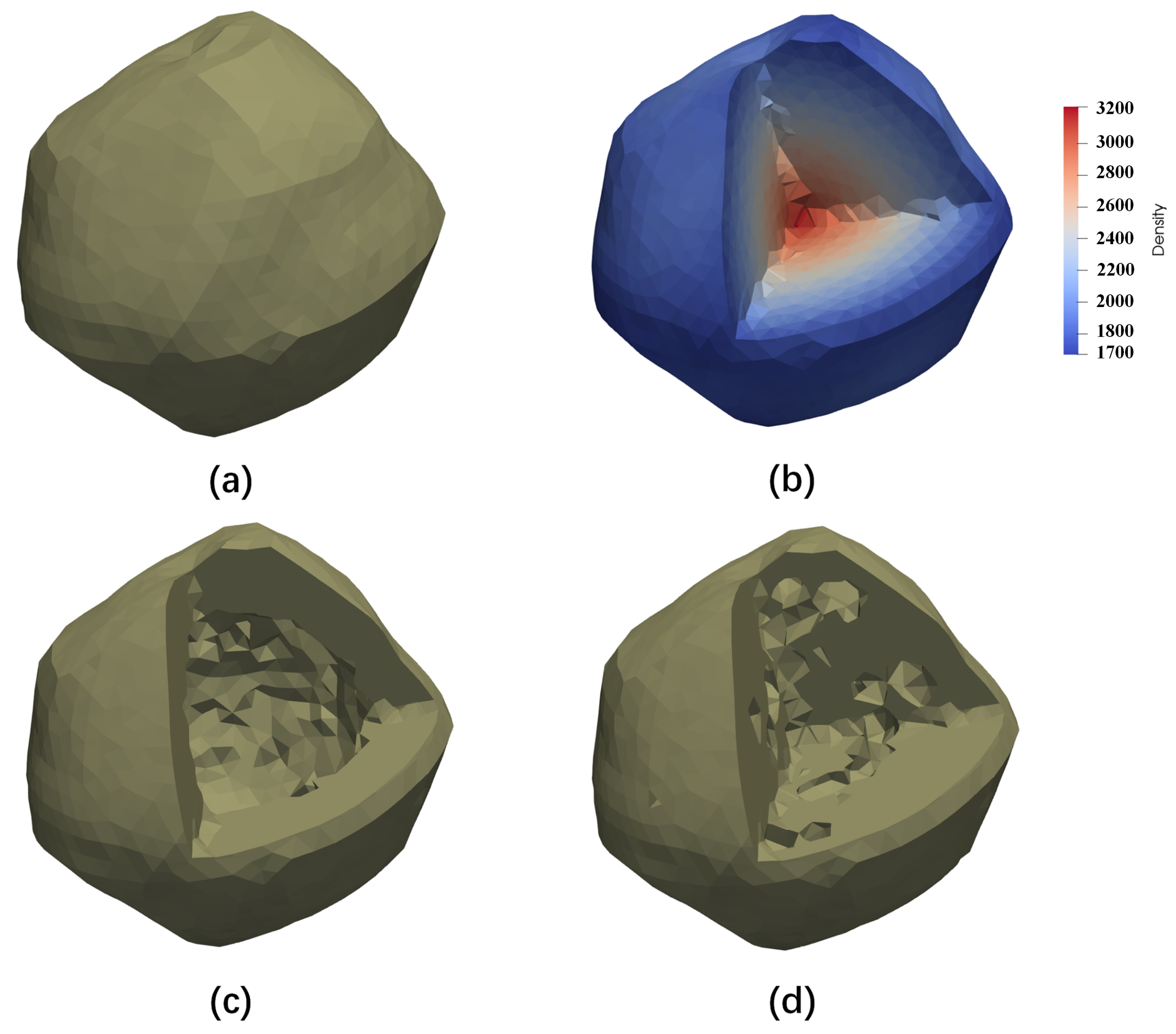
Now, if we learn about the information of the shape and internal mass distribution of a small body, we can model it using the finite element method, then calculate the corresponding spherical harmonic function coefficients using the above method. Below, we explain the accuracy of this method using the primary model of Didymos as an example. We keep the mass constant and adjust the internal structure of the primary using four models: (a) Uniform internal density distribution. (b) The density decreases from the inside to the outside, with the centre density set to 3.2 g / cm 2 (equivalent to the density of granite) and the surface density set to 1.6 g / cm 2 (equivalent to the density of sandy soil); (c) The internal structure is hollow. (d) The internal structure contains some holes (we implement this by removing some elements and replacing them with voids). The four models correspond to Figure A1a–d, respectively. Then, the spherical harmonic function coefficients are calculated using the above method. Some of these coefficients are shown in Table A1.
Figure A1. The internal structure of the primary: (a) Uniform internal mass distribution; (b) density decreases from inside to outside; (c) hollow structure; and (d) randomly distributed internal holes.
Mathematics 10 03757 g0a1
We calculated the orbits of the mass point around the primary over one month using the finite element method and the spherical harmonic function method, respectively. We set a random initial position and velocity for the mass point, with a distance 1200 m from the primary and whose velocity kept it in a circular orbit.
Table A1. The coefficients of the partial spherical harmonic functions of the four models corresponding to Figure A1.
Model (a)Model (b)Model (c)Model (d)
J 2 1.1806016 × 10 2 9.8940464 × 10 3 1.6734636 × 10 2 1.5034951 × 10 2
J 3 1.6620303 × 10 3 1.5130812 × 10 3 2.4893284 × 10 3 1.3309408 × 10 3
J 4 8.2823689 × 10 3 6.5632877 × 10 3 1.1255250 × 10 3 8.4519822 × 10 3
J 5 1.3132394 × 10 3 1.0301008 × 10 3 1.9799122 × 10 3 1.7177357 × 10 3
J 6 5.0458902 × 10 3 4.3363831 × 10 3 7.6811147 × 10 3 5.0889960 × 10 3
C 22 1.4205710 × 10 3 1.2214748 × 10 3 2.0914078 × 10 3 1.3592346 × 10 3
S 22 1.4884062 × 10 17 6.5408149 × 10 17 3.4962132 × 10 17 2.7487490 × 10 17
C 31 1.4205710 × 10 3 8.2970092 × 10 4 1.4993794 × 10 3 1.3687619 × 10 3
C 32 4.5358186 × 10 4 3.1217587 × 10 4 5.1968086 × 10 4 6.2947825 × 10 4
C 33 7.3986272 × 10 5 6.7329189 × 10 5 1.3757727 × 10 4 1.1369448 × 10 4
S 31 1.7122335 × 10 3 4.1793971 × 10 3 7.1960664 × 10 3 4.8583376 × 10 3
S 32 5.5112926 × 10 4 5.0319504 × 10 4 8.1352188 × 10 4 5.2487380 × 10 4
S 33 4.3490667 × 10 5 8.4002799 × 10 5 1.5102661 × 10 4 7.3761001 × 10 5
C 41 8.2756971 × 10 4 4.8424441 × 10 4 7.54612325 × 10 4 8.8267016 × 10 4
C 42 3.6264708 × 10 5 5.1243370 × 10 6 7.8521454 × 10 5 5.8103214 × 10 5
C 43 4.9772428 × 10 5 6.6087746 × 10 5 9.8008247 × 10 5 4.0274728 × 10 5
C 44 2.2303289 × 10 5 1.8673576 × 10 5 3.19242917 × 10 5 2.40624550 × 10 5
S 41 1.7122335 × 10 3 1.4349064 × 10 3 2.4430001 × 10 3 1.1834871 × 10 3
S 42 1.4850440 × 10 4 1.4613356 × 10 4 2.4425241 × 10 4 1.9224648 × 10 4
S 43 1.4255166 × 10 4 1.0462180 × 10 4 1.8717446 × 10 4 1.4832237 × 10 4
S 44 3.7897508 × 10 6 2.1443836 × 10 6 5.813172 × 10 7 4.12749518 × 10 6
C 51 3.1272871 × 10 5 3.4821246 × 10 5 6.8427557 × 10 5 5.3334476 × 10 5
C 52 1.3763895 × 10 5 9.4857243 × 10 6 1.8897903 × 10 5 1.2900471 × 10 5
C 53 1.5176728 × 10 5 1.0813339 × 10 5 1.9819451 × 10 5 2.3163710 × 10 5
C 54 1.3104122 × 10 6 1.7654773 × 10 6 3.5584973 × 10 6 1.5303503 × 10 6
C 55 1.1230563 × 10 7 3.5638557 × 10 8 2.0440055 × 10 8 4.6177160 × 10 7
S 51 3.0555771 × 10 4 2.5269240 × 10 4 3.9629143 × 10 4 1.9158968 × 10 4
S 52 8.3027337 × 10 5 5.5164301 × 10 5 1.0287761 × 10 4 6.4137630 × 10 5
S 53 2.1025676 × 10 5 1.9801873 × 10 5 3.2486021 × 10 5 1.9990395 × 10 5
S 54 8.5562671 × 10 7 4.0510217 × 10 7 9.9360799 × 10 7 3.4240771 × 10 7
S 55 5.6674802 × 10 7 7.9659473 × 10 7 1.3832809 × 10 6 1.2130380 × 10 6
C 61 7.4598908 × 10 5 1.0254846 × 10 5 1.3039376 × 10 4 1.0657605 × 10 4
C 62 2.2087532 × 10 5 8.6100296 × 10 6 2.6696073 × 10 5 1.5985003 × 10 5
C 63 8.0428517 × 10 6 7.3253673 × 10 6 1.1413149 × 10 5 9.1612740 × 10 6
C 64 4.0554689 × 10 7 4.0401878 × 10 8 1.9263216 × 10 7 2.1994592 × 10 7
C 65 1.2221950 × 10 7 8.2412156 × 10 8 1.54076076 × 10 7 2.1036180 × 10 7
C 66 3.6108293 × 10 8 5.009707 × 10 8 8.8044116 × 10 8 6.2420189 × 10 8
S 61 2.6668643 × 10 4 1.8252031 × 10 4 1.7433184 × 10 4 4.6283910 × 10 4
S 62 9.1296564 × 10 5 8.4002799 × 10 5 1.2608227 × 10 4 7.36740260 × 10 5
S 63 8.4915327 × 10 6 8.4002799 × 10 5 1.4218991 × 10 5 1.0994466 × 10 5
S 64 4.3587887 × 10 7 8.4002799 × 10 7 6.6267905 × 10 7 4.28696097 × 10 8
S 65 1.4568412 × 10 7 8.4002799 × 10 7 1.94633108 × 10 7 1.1636263 × 10 7
S 66 1.4975725 × 10 8 8.4002799 × 10 8 1.4714211 × 10 8 5.34328597 × 10 9
Figure A2 shows the distance between the orbital position of the mass point calculated by the spherical harmonic function method considering different perturbation terms and the position calculated by the finite element method; that is, the error in the calculated orbital positions of the spherical harmonic function method. The four figures correspond to the four models of the primary in Figure A1. Here, we take Figure A2a as an example to explain. The blue line indicates that only J 2 , J 3 , and J 4 of the zonal harmonic terms and T 2 of the tesseral harmonic terms were considered, which are the main perturbation terms for the calculation of the Earth’s gravitational field. The result shows bad performance in error maintenance, with a maximum error of 520.02 m within one month. The light blue line indicates that we added the tesseral harmonic terms T 3 and T 4 to the blue one, and the results show a significant reduction in the error, with a maximum error of 12.43 m within 30 days. The yellow line indicates that we added J 5 and T 5 to the light blue one, with a maximum error of 5.40 m within 30 days. The red line indicates the addition of J 6 and T 6 to the yellow case, and the calculation error was significantly reduced, with a maximum error of 2.35 m within 30 days.
Figure A2. The distance error between the orbit calculated by the spherical harmonic function method and the finite element method. (ad) correspond to the four models of the primary in Figure A1, and the different coloured lines indicate that different perturbation terms are considered, where J X indicates the expansion to the X th order of the zonal harmonic term and T X indicates the expansion to the X th tesseral harmonic term.
Mathematics 10 03757 g0a2
The results show that our method is effective. For longer simulation times, we can further calculate higher-order zonal and tesseral harmonic terms, such that the errors can be maintained within acceptable accuracy. This method imposes no restrictions on the shape and internal mass distribution of the small body. Furthermore, using this method, we can calculate the coefficients of the spherical harmonic function of any finite element model at once and call them in the orbit calculation, thus avoiding the high computational cost of the finite element method when calculating high-precision models.

References

  1. Cheng, A.; Michel, P.; Jutzi, M.; Rivkin, A.; Stickle, A.; Barnouin, O.; Ernst, C.; Atchison, J.; Pravec, P.; Richardson, D.; et al. Asteroid impact & deflection assessment mission: Kinetic impactor. Planet. Space Sci. 2016, 121, 27–35. [Google Scholar]
  2. Michel, P.; Cheng, A.; Küppers, M.; Pravec, P.; Blum, J.; Delbo, M.; Green, S.; Rosenblatt, P.; Tsiganis, K.; Vincent, J.B.; et al. Science case for the asteroid impact mission (AIM): A component of the asteroid impact & deflection assessment (AIDA) mission. Adv. Space Res. 2016, 57, 2529–2547. [Google Scholar]
  3. Cheng, A.F.; Rivkin, A.S.; Michel, P.; Atchison, J.; Barnouin, O.; Benner, L.; Chabot, N.L.; Ernst, C.; Fahnestock, E.G.; Kueppers, M.; et al. AIDA DART asteroid deflection test: Planetary defense and science objectives. Planet. Space Sci. 2018, 157, 104–115. [Google Scholar] [CrossRef]
  4. Rainey, E.S.; Stickle, A.M.; Cheng, A.F.; Rivkin, A.S.; Chabot, N.L.; Barnouin, O.S.; Ernst, C.M.; Group, A.I.S.W. Impact Modeling for the Double Asteroid Redirection Test Mission. In Proceedings of the Hypervelocity Impact Symposium, Destin, FL, USA, 16–20 April 2019; Volume 883556, p. HVIS2019-038. [Google Scholar]
  5. Rainey, E.S.; Stickle, A.M.; Cheng, A.F.; Rivkin, A.S.; Chabot, N.L.; Barnouin, O.S.; Ernst, C.M.; AIDA/DART Impact Simulation Working Group. Impact modeling for the Double Asteroid Redirection Test (DART) mission. Int. J. Impact Eng. 2020, 142, 103528. [Google Scholar] [CrossRef]
  6. Rivkin, A.S.; Chabot, N.L.; Stickle, A.M.; Thomas, C.A.; Richardson, D.C.; Barnouin, O.; Fahnestock, E.G.; Ernst, C.M.; Cheng, A.F.; Chesley, S.; et al. The double asteroid redirection test (DART): Planetary defense investigations and requirements. Planet. Sci. J. 2021, 2, 173. [Google Scholar] [CrossRef]
  7. Agrusa, H.; Richardson, D.; Barbee, B.; Bottke, W.; Cheng, A.; Eggl, S.; Ferrari, F.; Hirabayashi, M.; Karatekin, O.; McMahon, J.; et al. Predictions for the Dynamical State of the Didymos System Before and After the Planned DART Impact. LPI Contrib. 2022, 2678, 2447. [Google Scholar]
  8. Agrusa, H.F.; Gkolias, I.; Tsiganis, K.; Richardson, D.C.; Meyer, A.J.; Scheeres, D.J.; Ćuk, M.; Jacobson, S.A.; Michel, P.; Karatekin, Ö.; et al. The excited spin state of Dimorphos resulting from the DART impact. Icarus 2021, 370, 114624. [Google Scholar] [CrossRef]
  9. Agrusa, H.; Ballouz, R.; Meyer, A.J.; Tasev, E.; Noiset, G.; Karatekin, Ö.; Michel, P.; Richardson, D.C.; Hirabayashi, M. Rotation-induced granular motion on the secondary component of binary asteroids: Application to the DART impact on Dimorphos. Astron. Astrophys. 2022, 664, L3. [Google Scholar] [CrossRef]
  10. Werner, R.A.; Scheeres, D.J. Mutual potential of homogeneous polyhedra. Celest. Mech. Dyn. Astron. 2005, 91, 337–349. [Google Scholar] [CrossRef] [Green Version]
  11. Hirabayashi, M.; Scheeres, D.J. Recursive computation of mutual potential between two polyhedra. Celest. Mech. Dyn. Astron. 2013, 117, 245–262. [Google Scholar] [CrossRef]
  12. Hou, X.; Scheeres, D.J.; Xin, X. Mutual potential between two rigid bodies with arbitrary shapes and mass distributions. Celest. Mech. Dyn. Astron. 2017, 127, 369–395. [Google Scholar] [CrossRef]
  13. Richardson, D.C.; Quinn, T.; Stadel, J.; Lake, G. Direct large-scale N-body simulations of planetesimal dynamics. Icarus 2000, 143, 45–59. [Google Scholar] [CrossRef] [Green Version]
  14. Yu, Y.; Cheng, B.; Hayabayashi, M.; Michel, P.; Baoyin, H. A finite element method for computational full two-body problem: I. The mutual potential and derivatives over bilinear tetrahedron elements. Celest. Mech. Dyn. Astron. 2019, 131, 51. [Google Scholar] [CrossRef]
  15. Ruth, R.D. A canonical integration technique. IEEE Trans. Nucl. Sci. 1983, 30, 2669–2671. [Google Scholar] [CrossRef]
  16. Marsden, J.E.; West, M. Discrete mechanics and variational integrators. Acta Numer. 2001, 10, 357–514. [Google Scholar] [CrossRef] [Green Version]
  17. Feng, K.; Qin, M. Symplectic Geometric Algorithms for Hamiltonian Systems; Springer: Berlin/Heidelberg, Germany, 2010; Volume 449. [Google Scholar]
  18. Karamali, G.; Shiri, B. Numerical solution of higher index DAEs using their IAE’s structure: Trajectory-prescribed path control problem and simple pendulum. Casp. J. Math. Sci. CJMS 2018, 7, 1–15. [Google Scholar]
  19. Kosmas, O.T.; Vlachos, D. Phase-fitted discrete Lagrangian integrators. Comput. Phys. Commun. 2010, 181, 562–568. [Google Scholar] [CrossRef] [Green Version]
  20. Kosmas, O.T.; Vlachos, D. Local path fitting: A new approach to variational integrators. J. Comput. Appl. Math. 2012, 236, 2632–2642. [Google Scholar] [CrossRef] [Green Version]
  21. Kosmas, O.; Leyendecker, S. Analysis of higher order phase fitted variational integrators. Adv. Comput. Math. 2016, 42, 605–619. [Google Scholar] [CrossRef]
  22. Kosmas, O.; Leyendecker, S. Variational integrators for orbital problems using frequency estimation. Adv. Comput. Math. 2019, 45, 1–21. [Google Scholar] [CrossRef] [Green Version]
  23. Kosmas, O. Energy minimization scheme for split potential systems using exponential variational integrators. Appl. Mech. 2021, 2, 431–441. [Google Scholar] [CrossRef]
  24. Leimkuhler, B.; Reich, S. Simulating Hamiltonian Dynamics; Cambridge University Press: Cambridge, UK, 2004; Number 14. [Google Scholar]
  25. Dullweber, A.; Leimkuhler, B.; McLachlan, R. Symplectic splitting methods for rigid body molecular dynamics. J. Chem. Phys. 1997, 107, 5840–5851. [Google Scholar] [CrossRef] [Green Version]
  26. Kol, A.; Laird, B.B.; Leimkuhler, B.J. A symplectic method for rigid-body molecular simulation. J. Chem. Phys. 1997, 107, 2580–2588. [Google Scholar] [CrossRef] [Green Version]
  27. van Zon, R.; Schofield, J. Symplectic algorithms for simulations of rigid-body systems using the exact solution of free motion. Phys. Rev. E 2007, 75, 056701. [Google Scholar] [CrossRef] [PubMed]
  28. Celledoni, E.; Fassò, F.; Säfström, N.; Zanna, A. The exact computation of the free rigid body motion and its use in splitting methods. SIAM J. Sci. Comput. 2008, 30, 2084–2112. [Google Scholar] [CrossRef]
  29. Ćuk, M.; Jacobson, S.A.; Walsh, K.J. Barrel Instability in Binary Asteroids. Planet. Sci. J. 2021, 2, 231. [Google Scholar] [CrossRef]
  30. Benner, L.A.; Margot, J.; Nolan, M.; Giorgini, J.; Brozovic, M.; Scheeres, D.; Magri, C.; Ostro, S. Radar imaging and a physical model of binary asteroid 65803 Didymos. In Proceedings of the AAS/Division for Planetary Sciences Meeting Abstracts #42, Pasadena, CA, USA, 4–8 October 2010; Volume 42, pp. 13–17. [Google Scholar]
  31. Hand, L.N.; Finch, J.D. Analytical Mechanics; Cambridge University Press: Cambridge, UK, 1998. [Google Scholar]
  32. Gao, Y.; Yu, Y.; Cheng, B.; Baoyin, H. Accelerating the finite element method for calculating the full 2-body problem with CUDA. Adv. Space Res. 2022, 69, 2305–2318. [Google Scholar] [CrossRef]
  33. Naidu, S.; Benner, L.; Brozovic, M.; Nolan, M.; Ostro, S.; Margot, J.; Giorgini, J.; Hirabayashi, T.; Scheeres, D.; Pravec, P.; et al. Radar observations and a physical model of binary near-Earth asteroid 65803 Didymos, target of the DART mission. Icarus 2020, 348, 113777. [Google Scholar] [CrossRef]
  34. Gao, Y.; Cheng, B.; Yu, Y. The interactive dynamics of a binary asteroid and ejecta after medium kinetic impact. Astrophys. Space Sci. 2022, 367, 84. [Google Scholar] [CrossRef]
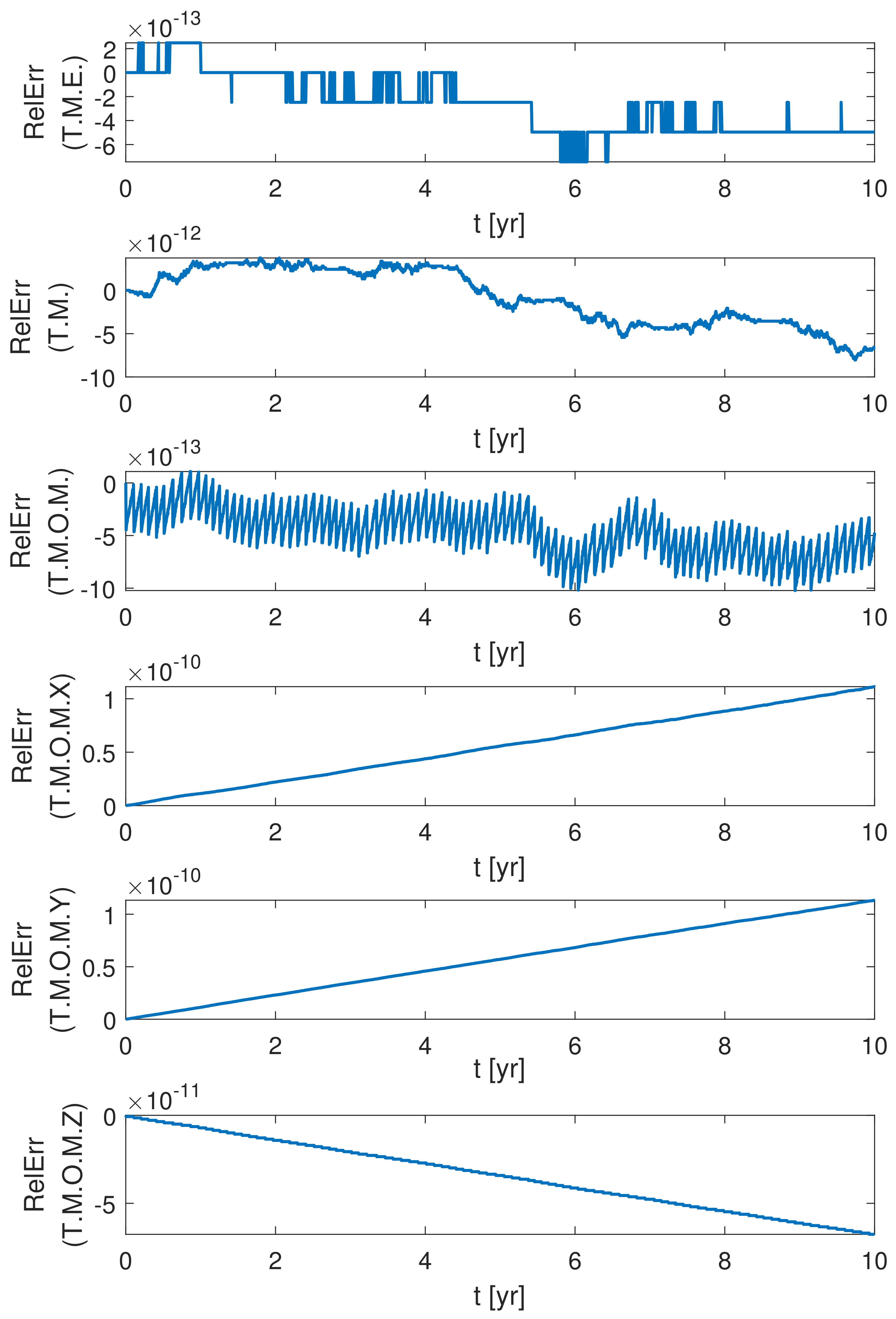
Figure 1. Variation of the relative error of the conserved quantities over ten years for simulations of the full two-body problem using the RK4 integrator.
Mathematics 10 03757 g001
Figure 2. Variation of the relative error of the conserved quantities over ten years for simulations of the full two-body problem using the RK78 integrator.
Mathematics 10 03757 g002
Figure 3. Variation of the relative error of the conserved quantities over ten years for simulations of the full two-body problem using the SI integrator.
Mathematics 10 03757 g003
Figure 4. Diagram of the 1-2-3 Euler angles of the secondary: (a) diagram of the Didymos system; and (b) the simplified model.
Mathematics 10 03757 g004
Figure 5. Variation of the three Euler angles of the secondary over time: (a) initial spin angular velocity = 1.0 ω 0 and (b) initial spin angular velocity = 1.5 ω 0 .
Mathematics 10 03757 g005
Figure 6. The distribution of the eigenvalues of M ( t ) at t = 8000 s, 110,000 s, 623,000 s, and 990,000 s, where the initial angular velocity of the secondary is 1.0 ω 0 .
Mathematics 10 03757 g006
Figure 7. The distribution of the eigenvalues of M ( t ) in 10 6 s, with initial angular velocity of the secondary of 1.0 ω 0 .
Mathematics 10 03757 g007
Figure 8. The maximum eigenvalue of M ( t ) and the corresponding eigenvector component in the ϕ -direction, where the initial angular velocity of the secondary is 1.0 ω 0 : (a) Variation of the modulus of the maximum eigenvalue over 10 6 s seconds; and (b) the component of the eigenvector in the ϕ -direction corresponding to the maximum eigenvalue.
Mathematics 10 03757 g008
Figure 9. Components of the eigenvector in the x-direction and y-direction corresponding to the maximum eigenvalue.
Mathematics 10 03757 g009
Figure 10. Distribution of the eigenvalues of M ( t ) over 10 6 s seconds. (a,b) The initial angular velocity of the secondary is 1.1 ω 0 . (c,d) The initial angular velocity of the secondary is 1.2 ω 0 . (e,f) The initial angular velocity of the secondary is 1.3 ω 0 .
Mathematics 10 03757 g010
Figure 11. The variation of the modulus of the eigenvalues of M ( t ) and the components of the eigenvector in the ϕ - and θ -directions corresponding to the eigenvalues over 10 6 s, where the initial angular velocity of the secondary is 1.3 ω 0 . (a) Modulus of the 1st eigenvalue. (b) Modulus of the 2nd eigenvalue. (c) Modulus of the 3rd eigenvalue. (d) ϕ of the 1st eigenvector. (e) ϕ of the 2nd eigenvector. (f) ϕ of the 3rd eigenvector. (g) θ of the 1st eigenvector. (h) θ of the 2nd eigenvector. (i) θ of the 3rd eigenvector.
Mathematics 10 03757 g011
Figure 12. The distribution of the eigenvalues of M ( t ) over 10 6 seconds, where the initial angular velocity of the secondary is 1.4 ω 0 (a) and 1.5 ω 0 (b).
Mathematics 10 03757 g012
Figure 13. The maximum ϕ value under different perturbation terms and initial angular velocities within 1 year.
Mathematics 10 03757 g013
Figure 14. The maximum ϕ value under different a / b , b / c , and initial angular velocity within 1 year.
Mathematics 10 03757 g014
Publisher’s Note: MDPI stays neutral with regard to jurisdictional claims in published maps and institutional affiliations.