Article

Modelling, Simulation and Controlling of a Multi-Pump System with Water Storage Powered by a Fluctuating and Intermittent Power Source

Department of Automation and Applied Informatics, Politehnica University of Timisoara, Vasile Parvan, No. 2, 300223 Timisoara, Romania
*
Authors to whom correspondence should be addressed.
Mathematics 2022, 10(21), 4019; https://doi.org/10.3390/math10214019
Submission received: 29 September 2022 / Revised: 24 October 2022 / Accepted: 26 October 2022 / Published: 29 October 2022
(This article belongs to the Special Issue Control Theory and Applications)

Abstract

:
In recent years, many pumping systems have begun to be powered by renewable energy generators, including mostly photovoltaic generators and, less frequently, electrical wind generators. Because of the technology’s complexity and novelty (it has not yet reached its maturation), most of those systems consist of single pumps powered by photovoltaic generators or electrical wind generators. For this reason, the current paper proposes a strategy for driving a multi-pump system with water storage powered by a fluctuating and intermittent power source, such as power grids, which are limited by price variation over different periods during the day, or photovoltaic generators and/or electrical wind generators. The current work begins by proposing a model of a multi-pump system with water storage, followed by the design of a control strategy for operating such a system powered by a fluctuating and intermittent power source in an energy-efficient manner, without sacrificing the reliability, robustness and lifetime of the plant. Finally, an analysis of two concrete situations encountered in practice is made: in one, the considered multi-pump system is powered only by a power grid limited by price variation over three periods; in the other, it is powered by a photovoltaic generator.

1. Introduction

Pumping systems are used for pressurizing and transporting the water from a source to the consumer. Those systems are extensively used in a wide range of industries, such as urban water supply networks, agricultural irrigation and power plants [1]. Nowadays, pumping systems consume around 30% of the electrical energy produced globally [2]. In the European Union, the pumping systems represent approximately 20% of the industrial and agricultural electrical energy consumption, and in China, they account for 40% of the generated electrical energy [3,4,5,6]. Due to the enormous size of this market, reducing the energy consumption and increasing the energy saving in this sector is essential.
In recent decades, in order to reduce the operating costs related to the energy consumption and increase the energy savings in this sector, most of the pumping systems have been technologically upgraded by using more efficient pump control systems (implementing algorithms that ensure energy optimization, better pump scheduling and real-time control, etc.) [7,8]. Additionally, some pumping systems have been technologically upgraded with renewable energy generators, including mostly photovoltaic generators [9] and, less frequently, electrical wind generators [10], to further reduce the operating costs related to energy consumption.
Due to the technology’s complexity and novelty (it has not yet reached its maturation), most of those systems that have been upgraded with photovoltaic generators or electrical wind generators consist of single pumps. This is because, in multi-pump systems, the pumps might operate far away from the most efficient region, leading to low reliability and a high failure rate due to cavitation, flow recirculation, the wear of the bearings, influences on the physical parameters of the processed fluid, etc. [11,12,13,14,15].
Although many researchers have investigated how to increase the efficiency and reduce the energy consumption without sacrificing the reliability and the life expectancy of a multi-pump system [11,12,16,17,18,19], all those studies take into consideration a stable and almost infinite power source, such as a power grid, without any limitations on the operating periods. None of the research takes into consideration a fluctuating and intermittent power source, such as power grids limited by price variation in different periods during the day, photovoltaic generators or wind electrical generators [20].
Given the above remarks, the major objectives of the current paper, which offers a contribution, consist of the development and validation of an adequate model and control strategy for a multi-pump system with water storage powered by a fluctuating and intermittent power source in an efficient energy manner, without sacrificing the operation and lifetime of the system. Many advanced control strategies can be implemented to solve the issues addressed by the current work, such as robust control [21,22], model predictive control [21] or fuzzy logic control [22], etc., but they constitute future work, as in the current paper, the developed control strategy consists of a general system controller that manages the individual pumps. The controlling strategy of the submersible pumps is formed of two PI (proportional and integral) current regulators operating in parallel, while for the surface pump, another two PI controllers were added in cascade to the PI current regulators.

2. Modelling of the Multi-Pump System

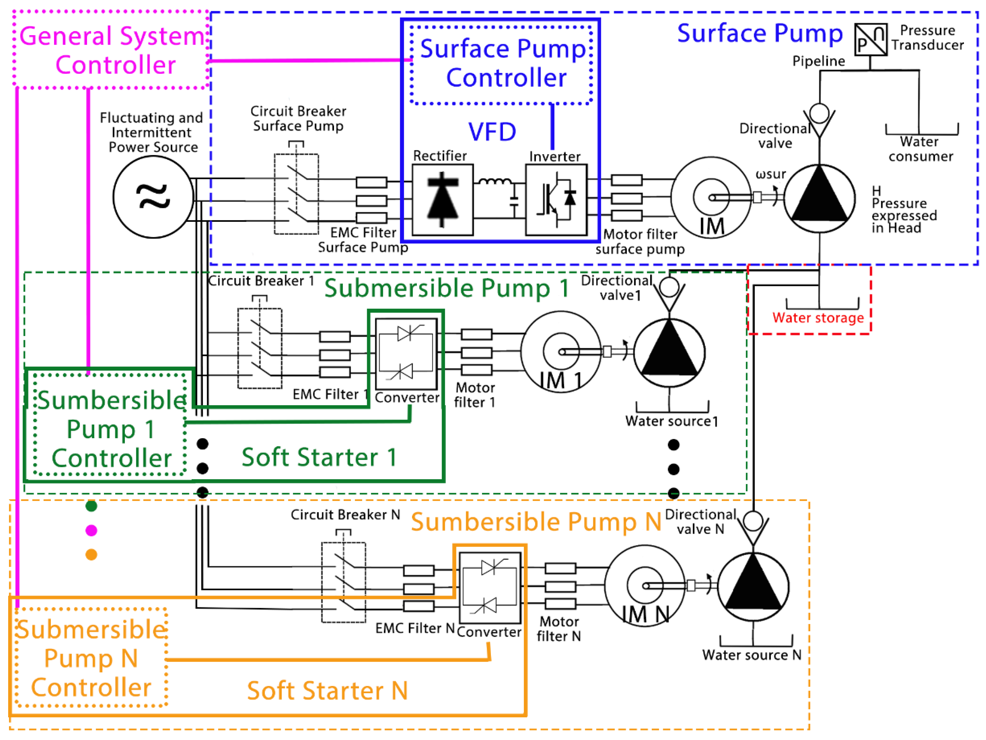
The considered multi-pump system is located in Morocco, North Africa [23], and it is used for irrigating a fruit tree orchard, with a layout typical of irrigation systems in regions with water resources deficit (such as Africa, South America, Australia, etc.). Figure 1 presents the layout of a general irrigation system in such regions, with several (n) submersible pumps used for collecting the water from several (n) aquifers in a water storage, from which it is further distributed to an irrigation network by a surface pump.
The considered system consists of four identical submersible pumps [24] (n = 4 in Figure 1) pumping water from four different wells to the water storage unit (pool), with a capacity of 25,000 m3. The dynamic water level in each well (100 m, 98 m, 100 m and 105 m), together with the extracted flow by each submersible pump (38.52 m3/h, 38.88 m3/h, 31.68 m3/h and 41 m3/h), was measured at the site location with the help of a probe and an ultrasonic flow meter (for full details, please see Table A1 in Appendix A). The water from the pool is distributed to an irrigation network by a surface pump [25] with an average flow of 158.5 m3/h. Currently, the entire system is powered by an electrical grid with three price periods (standard, peak and off-peak) but, in the future, it needs to be hybridized with a photovoltaic generator so as to further reduce the system operating expenses.

2.1. Irrigation Network

The surface pump distributes the water from the pool to the irrigation network at a pressure of 3.7 bars and an average flow of 158.5 m3/h. In Appendix A, Table A1, one can see the operating points and technical specifications of the surface pump [25].
The hydraulic network characteristic curve at the nominal operation H0 is obtained using Equation (1) from [26]:
H 0 = H g + k · ( Q 0 ) 2
where Hg is the static head (HG_CONSUMER_S in Figure 1), Q0 is the nominal pumping flow rate and k is the head loss coefficient [27].
The nominal hydraulic power Phid0 required for operating the irrigation system is calculated using Equation (2) from [28]:
P h i d 0 = ρ · g · H 0 · Q 0
where ρ is the water density and g is the gravitational acceleration.
Appendix A, Table A1, presents the technical specifications of the submersible [24] and surface [25] pumps.
A list of all the variable denotations used in the paper is presented in Abbreviations part.

2.2. Water Storage (Pool)

The water storage is modelled as a pool with a capacity of Vpool = 25,000 m3, which balances the water volume extracted from the pool by the surface pump, with the water volume discharged to the pool by the submersible pumps, as in Equation (3):
V p o o l . i n = V p o o l . o u t

2.3. Pumps

The four identical submersible pumps [24] collect the water from four different wells and deliver it to the water storage unit. Appendix A, Table A1, presents the technical specifications in addition to the operating points of the submersible pumps [24].
  • The first pump is installed at a depth of 120 m below ground level (PUMP_1_DEPTH ≈ 120 m in Figure 1) and the water dynamic level is 100 m (HG_WATER_SOURCE_1 ≈ 100 m in Figure 1). The maximum extractable flow from the well is 41 m3/h, but the pump operates at the nominal flow of 38.52 m3/h at 50 Hz. The second pump is installed at a depth of 120 m below ground level (PUMP_2_DEPTH ≈ 120 m in Figure 1), and the water dynamic level is 98 m (HG_WATER_SOURCE_2 ≈ 98 m in Figure 1). The maximum extractable flow from the well is 41 m3/h, but the pump operates at the nominal flow of 38.88 m3/h at 50 Hz.
  • The third pump is installed at a depth of 120 m below ground level (PUMP_3_DEPTH ≈ 120 m in Figure 1), and the water dynamic level is 100 m (HG_WATER_SOURCE_3 ≈ 100 m in Figure 1). The maximum extractable flow from the well is 41 m3/h, but the pump operates at the nominal flow of 31.68 m3/h at 50 Hz. The fourth pump is installed at a depth of 120 m below ground level (PUMP_4_DEPTH ≈ 120 m in Figure 1), and the water dynamic level is 105 m (HG_WATER_SOURCE_4 ≈ 105 m in Figure 1). The maximum extractable flow from the well is 41 m3/h, but the pump operates at the nominal flow of 40 m3/h at 50 Hz.
The centrifugal (four submersible and one surface) pumps are modeled based on A, B and C coefficients (for the values, see Table A1 in Appendix A). The coefficients are identified through quadratic regression using the Matlab curve fitting tool, with the pump head–flow (H0Q0) curve at 50 Hz provided by the manufacturer [24,25]. Similarly, in Equation (5), the D and E coefficients (for the values, see Table A1 in Appendix A) are also identified using the efficiency–flow (η0Q0) curve at 50 Hz [24,25]. Starting with Equation (4) [29], the subscript “0” stands for the nominal values (η0, the nominal pump efficiency):
H 0 = A + B · Q 0 + C · ( Q 0 ) 2
η 0 = D · Q 0 + E · ( Q 0 ) 2
In Equation (6), α denotes the ratio between the pump operating speed (ω) and nominal speed (ω0):
α = ω / ω 0
The response of the centrifugal pump to various speeds is modelled using the pump affinity laws [30]: the pump flow variation (Equation (7)), head variation (Equation (8)) and power variation (Equation (9)):
Q Q 0 = ω ω 0 · ( G G 0 ) 3
H H 0 = ( ω ω 0 ) 2 · ( G G 0 ) 2
P p u m p P p u m p 0 = ( ρ ρ 0 ) · ( ω ω 0 ) 3 · ( G G 0 ) 5
where Ppump stands for the pump’s required mechanical (rotational) power and, in the current work, the change in the water density (ρ) and pump geometry (G) during the speed variation are considered constant (ρ = ρ0, G = G0).
By combining the pump head–flow (H0Q0) curve at the nominal speed (ω0) from Equation (4) with the pump affinity laws from Equations (6)–(9), the pump characteristic head–flow curve (HQ) is expressed in Equation (10) as a function of the pump speed variation:
H = α 2 · A + α · B · Q + C · Q 2
Combining the pump characteristic defined by Equation (10) with the hydraulic network characteristic curve from Equation (1), Equation (11) is obtained:
H g + k · Q 2 = α 2 · A + α · B · Q + C · Q 2
From Equation (11), only the positive solution represents the actual pump discharge according to the pump speed variation (Q(ω)) because of the negative value of the C coefficient (see Table A1 in Appendix A). In Equation (12), only Bhaskara’s solution with “-” is considered:
Q ( ω ) = α · B α 2 · B 2 4 · [ α 2 · A H g ] · ( C k ) 2 · ( C k )
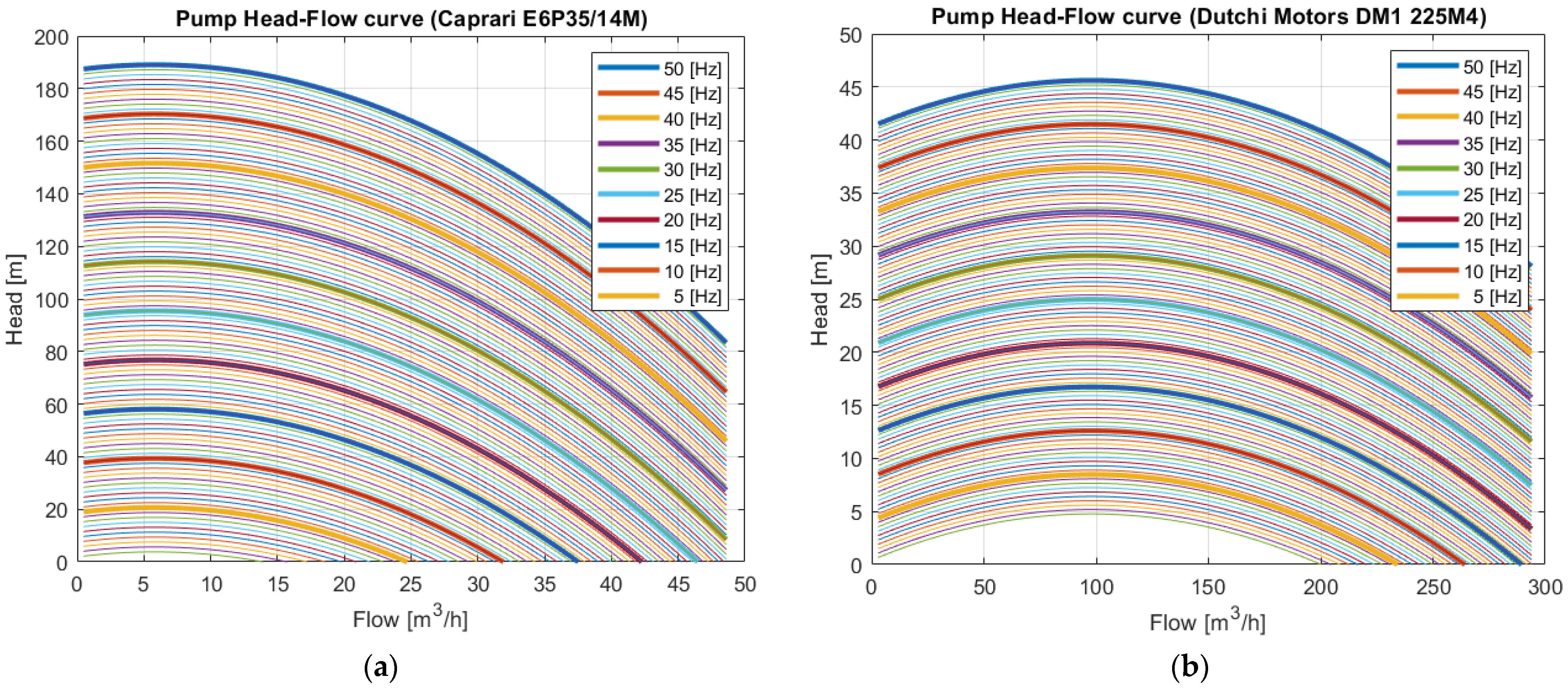
Figure 2 shows the pump characteristic head–flow (HQ) curves (pumping head in meters on the x-axis and flow in m3/h on the y-axis) at different speeds (equivalent to frequency variations from 5 to 50 Hz) for the four identical submersible pumps used for collecting the water from the wells in Figure 2a and for the surface pump used for distributing the water to the irrigation network in Figure 2b.
In Appendix A, Table A1, Figure 2a shows that the submersible pumps operating over 38 Hz avoid vacuum operation (when the pump propeller rotates without pumping any water, heating the motor until it short-circuits). Figure 2b shows that the surface pump must operate over 40 Hz to ensure correct irrigation (by providing the necessary pressure for the entire irrigation network).
In the current paper, the pump efficiency at a partial load is calculated using [31], by combining the pump efficiency–flow (η0Q0) curve at the nominal speed (ω0) from Equation (5) with the pump affinity laws (Equations (6)–(9)). The resulting equation is represented in (13), where the pump efficiency variation is expressed based on the speed variation:
η = 1 ( 1 η 0 ) · ( Q 0 Q ) 0.1
Figure 3 shows the pump efficiency (ηQ) curves (efficiency as a percentage on the x-axis and flow in m3/h on the y-axis) at different speeds (equivalent to frequency variations from 5 to 50 Hz) for the four identical submersible pumps in Figure 3a and surface pump in Figure 3b.
From Figure 3a it can be seen that the efficiency of all the submersible pumps is around 75%, considering an operating flow between 32 and 40 m3/h and an operating frequency of 50 Hz. Figure 3b confirms the well-known fact that the efficiency of a surface pump is higher than the efficiency of a submersible pump. Figure 3b also shows that the surface pump has an efficiency of around 80% at an operating flow of 158.5 m3/h and a frequency over 40 Hz.
By combining the hydraulic network characteristic curves of each pump, Equation (1), with the head–flow (HQ) curves, and Equations (10)–(12), with the pumps efficiency variation based on the pumps speed variations (ηQ) from Equation (13), can be combined to obtain the iso-efficiency curves (Figure 4, pumping head in meters on the x-axis, flow in m3/h on the y-axis). The pump efficiencies are represented as percentages by the dotted lines, while the pump frequencies are represented in Hz by the dashed lines. In order to operate the pumps close to their optimal operation, the pumping system control strategy must be developed based on the operating points of the four identical submersible pumps (Figure 4a) and the hydraulic network characteristic curve (Figure 4b).
In Figure 4a, one can see the operating performance (total head, discharge and efficiency) of each submersible pump. The total heads of the pumps, including the well dynamic head of the lowest water level and all the pressure losses, are 127 m, 126, 141 and 121.5 m (following the order given in Figure 4a and Table A1 in Appendix A). The submersible pumps efficiencies are around 75%, and for a pump frequency variation over 40 Hz, the surface pump gives a flow ranging from 135 m3/h (40 Hz and 28 m) to 174 m3/h (50 Hz and 43 m), with an efficiency of around 80%.
The operating hydraulic power (Phid) is obtained by substituting in the nominal hydraulic power from Equation (2), including the nominal head (H0) and flow (Q0), with the operating head (H) and flow (Q) of each pump (four submersible and one surface). The pumps’ required mechanical (rotational) power (Ppump) is obtained using Equation (14) through the division of the operating hydraulic powers (Phid) with the pump efficiencies (η) at their operating point [26]:
P p u m p = P h i d η = ρ · g · H · Q ω · η  
The pump torque (Tpump) is calculated based on the division of the pumps’ required power (Ppump) with the pump speed (ω), using Equation (15):
T p u m p = P p u m p ω = ρ · g · H g · Q + ρ · g · k · ( Q ( ω ) ) 3 ω · ( 1 ( α ) 0.1 + D · Q ( ω ) · ( α ) 1.1 + E · ( Q ( ω ) ) 2 · ( α ) 2.1 )  
The pump inertia (Ipump) is calculated by Equation (16), using [32]:
I p u m p = 0.03768 · ( ρ · g · H g · Q + ρ · g · k · ( Q ( ω ) ) 3 ( 1 ( α ) 0.1 + D · Q ( ω ) · ( α ) 1.1 + E · ( Q ( ω ) ) 2 · ( α ) 2.1 ) 1000 · ω ) 0.9556

2.4. Induction Motors

All the pumps are driven by induction motors. In Appendix A, Table A2, one can see the technical parameters of the induction motors that drive the submersible [24] and surface [25] pumps.
The stator current vector i s s and rotor flux linkage Ψ r s of the induction motor are obtained using the electromagnetic Equations (17)–(22) [33]:
i s s ˙ = L r · ( L r · R s + L s · R r L s · R r · σ ) · i s s + L m · ( R r L r · j · ω ) · Ψ r s + L r 2 · v s s σ · L s · L r 2
Ψ r s ˙ = L m · R r · i s s ( R r L r · j · ω ) · Ψ r s L r
With   σ = 1 ( L m ) 2 L s · L r
where Ψ r s is the rotor flux, ω is the rotor speed, v s s is the stator voltage vectors, Rs and Rr represent the stator and rotor resistance, and Lm, Ls and Lr are the mutual, stator and rotor inductances, respectively.
The electromagnetic torque of the induction motor Tem is calculated using Equation (20), while the input power of the induction motor PIM is calculated using Equation (21) [34]:
T e m = 3 2 · p m o t o r · L m L r · I m { ψ r s · i s s }
P I M = 3 2 · R e { v s s · i s s }
where pmotor represents the induction motor’s number of pole pairs.

2.5. Induction Motor Drives

The induction motors of the four identical submersible pumps are driven by soft starters [35], while the induction motor of the surface pump is driven by a variable frequency drive (VFD) [36] that also executes the pressure control.
In Equation (22), the efficiency of the motor drive is calculated based on the nominal (Pdrivenominal) and maximum output powers and three experimental parameters, representing: k0—the no-load losses, k1—the losses linearly depending on the current (voltage drop across the diodes) and k2—the losses depending on the square of the current (resistive losses) [37]:
η d r i v e = p p · ( k 0 + k 1 · P I M + k 2 · ( P I M ) 2 )
where p = PIM/Pdrivenominal, with the Pdrivenominal being the nominal power of the induction motor drive.
The AC electrical power required (input) by the drive is:
P d r i v e = P I M / η d r i v e / η f i l t e r / η c a b l e s
where Pdriveinput is the electrical power required by the induction motor drive, ηdrive is the drive efficiency, ηfilter is the DV/DT filter efficiency and ηcables is the efficiency after the loss due to the voltage drop in the cables (typically between 1 and 3%). In Appendix A, Table A3 presents the technical parameters of the VFD [36].

3. The Proposed Control Strategy

Figure 5 presents the structure of the multi-pump control system formed of two levels. The first level consists of one surface pump controller (Sr.PC) that controls the irrigation pressure by driving the induction motor at various frequencies and the submersible pump controllers (Sm.PC). It can be also seen that the induction motor of the surface pump is driven by a VFD (variable frequency drive), while the induction motors of the submersible pumps are driven by soft starters. Both motor drives contain, in addition to the controllers, the execution elements (rectifier + inverter, respectively converter). Furthermore, the VFD controller is named Sr.PC, while the soft starters controllers are named Sm.PC (from 1 to n). The second level is a general system controller (GSC), which manages the operation of each pump (all pumps) based on the water level in the pool (water storage) and the generator’s available power.

3.1. General System Controller (GSC)

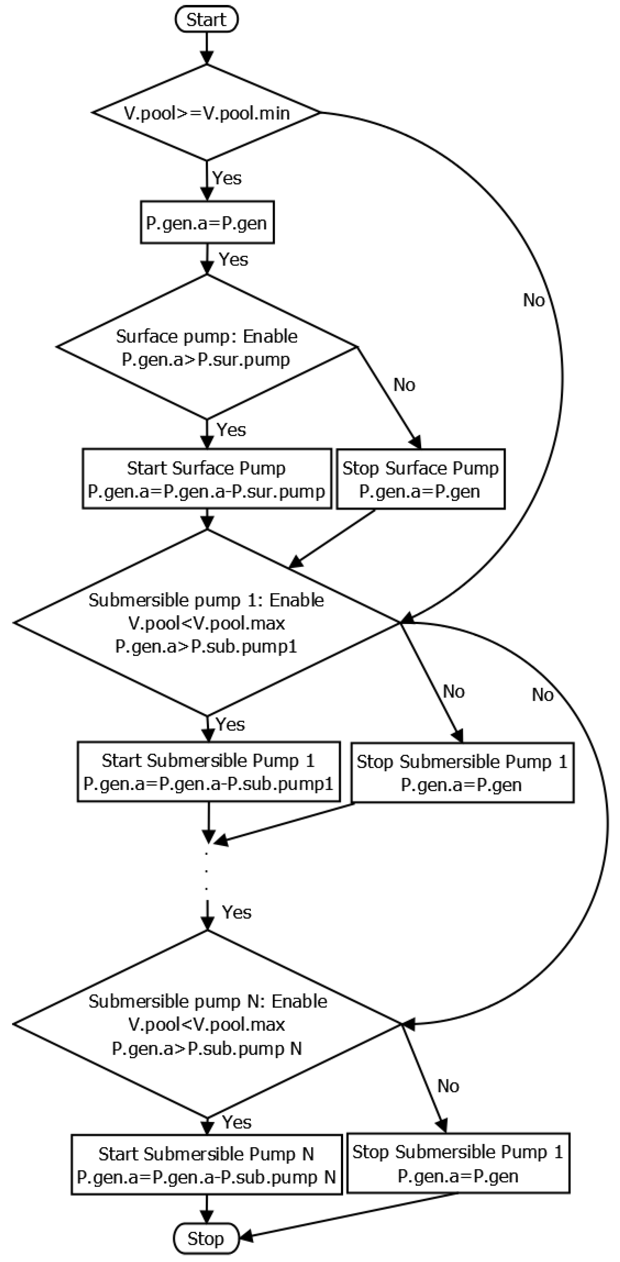
Figure 6 presents the flow chart of the general system controller.
If the water level in the pool (water storage) is not at a minimum level, and the user has programmed the irrigation and has enabled the surface pump to be operable, the GSC verifies whether the available power in the generator is higher than the power necessary for starting the surface pump and gives the order to start the surface pump operation while updating the available power. If any of those conditions are not met, no actions are taken, and the system receives the order to stop the surface pump in a case where it is already running. The next step consists of verifying whether there is still room to pump some water in the pool and, based on the submersible pumps’ availability and priorities (introduced by the user), the pumps start their operation according to the power available in the generator. The generator’s available power refers to the power generated by a photovoltaic generator or electrical wind turbine or the contracted power from the electrical grid according to the electricity consumption schedule or contract of the user, less the power already in use by the operating pumps.

3.2. Submersible Pump Controllers (Sm.PC)

The submersible pump induction motors are controlled by soft starters that control the acceleration at the nominal speed (equivalent frequencies ranging from 0 to 50 Hz) and deceleration from the nominal speed (equivalent frequencies ranging from 50 Hz to 0 Hz) of the induction motors. As can be seen in Figure 7, they are controlled using a classical solution for current regulation in vector-controlled AC drives, called the current regulator, considering a PI-type regulator. This current regulator is tuned using the pole-zero cancellation method based on the second-order equivalent system of the induction motor currents [38].
Legend [33]:
  • vds and vqs are the stator three-phase AC voltage commands transformed in the synchronous (dq) reference frame;
  • vαs and vβs are the stator three-phase AC voltage commands transformed in the stationary (αβ) reference frame;
  • vas, vbs, vcs are the stator three-phase AC voltage commands;
  • ias, ibs, ics are the stator three-phase AC currents;
  • iα and iβ are the stator three-phase AC currents expressed in the stationary (αβ) reference frame;
  • PWM = pulse width modulation;
  • Sa, Sb, Sc are the switching commands (orders);
  • Tdq.αβ = transformation from the synchronous (dq) reference frame into the stationary (αβ) reference frame;
  • Tabc.αβ = transformation from the three-phase (abc) complex space vector to the stationary (αβ) reference frame;
  • Tαβ.dq = transformation from the stationary (αβ) reference frame into synchronous (dq) reference frame;
  • Tαβ.abc = transformation from the stationary (αβ) reference frame to the three-phase (abc) complex space vector.
In this case:
T α β . d q = [ cos θ s sin θ s sin θ s cos θ s ] T d q . α β = [ cos θ s sin θ s sin θ s cos θ s ] 1 T a b c . α β = [ 2 / 3 1 / 3 1 / 3 0 3 / 3 3 / 3 1 / 3 1 / 3 1 / 3 ] T α β . a b c = [ 1 0 1 1 / 2 3 / 2 1 1 / 2 3 / 2 1 ]
For the second-order transfer functions of the closed-loop systems, in which i d s is the reference and ids is the output of the d-axis (real component) current loop, respectively, and i d s is the reference and iqs is the output of the q-axis (imaginary component) current loop, we consider the following forms [38]:
i d s ( s ) i d s ( s ) = s · k p 1 + k i 1 s 2 · ( σ · L S ) + s · ( R S + k p 1 ) + k i 1  
i q s ( s ) i q s ( s ) = s · k p 1 + k i 1 s 2 · ( σ · L S ) + s · ( R S + k p 1 ) + k i 1  
where
σ = 1 ( L m ) 2 L s · L r
is the leakage coefficient [36]. Rs (0.095 [Ω]) and Rr (0.063 [Ω]) represent the stator and rotor resistance of the induction motor, and Lm (0.032 [H]), Ls (0.034 [H]) and Lr (0.034 [H]) are the magnetizing, stator and rotor inductances of the induction motor. kp1 and ki1 represent the proportional and integral gains of the d- and q-axis currents systems. In general, in both loops, the current regulators are equally tuned.
The tuning of the Sm.PC is performed considering that the closed loop denominator of Equations (25) and (26) are matched with a standard second-order system denominator [38]:
s 2 · ( σ · L S ) + s · ( R S + k p 1 ) + k i 1 = s 2 + 2 · ξ 1 · ω n 1 · s + ( ω n 1 ) 2    
Developing Equation (28), we obtain:
s 2 + s · ( R S + k p 1 σ · L S ) + k i 1 σ · L S = s 2 + 2 · ξ 1 · ω n 1 · s + ( ω n 1 ) 2    
where ωn1 and ξ1 are the first natural frequency and damping factor of the system.
From Equation (29), we find that the required proportional and integral gains are:
k p 1 = σ · L s · 2 · ξ 1 · ω n 1 R s
and, respectively,
k i 1 = σ · L s · ( ω n 1 ) 2
For a critically damped response, the second-order denominator Equations (28) and (29) must give a solution with double real poles, a solution obtainable only with a damping factor equal to 1, ξ1 = 1:
For   ξ 1 = 1   results   ( s + ω n 1 ) 2
In [38], it is recommended that the dynamics of the closed-loop system be selected to be faster than the one of the open-loop system. In the current work, the poles of the closed-loop system (ωn1) are chosen to be 10 times greater than the open-loop poles (σLs/Rs):
ω n 1 = 10 σ · L s R s
leading to good results.

3.3. Surface Pump Controller (Sr.PC)

The surface pump induction motor is controlled by the VFD (variable frequency drive), which, in addition to controlling the acceleration and deceleration of the induction motor, also controls the operating speed, which can differ from the nominal one. For this reason, the Sr.PC uses the same closed-loop systems as the Sm.PC, with the same transfer Equations (25) and (26), to which a speed controller is added in cascade (Figure 7). The speed controller (from the main loop) provides the electromechanical torque, which becomes the q-axis current ( i d s ) as a reference for an inner loop, including the current regulation (q-axis), using Equation (34) from [39]:
T e m = K T · Ψ d r · i q s    
which allows us to obtain the q-axis current reference, i d s .
The synthesis of the speed controller is obtained, starting with Equation (35) [39], where the viscous friction is neglected:
T e m T p u m p = I p u m p · ( ω ˙ ) = 2 · π · I p u m p p m o t o r · ( f m )   ˙
where pmotor represents the pole pairs of the induction motor and fm represents the motor electrical frequency:
( f m = p m o t o r · ω / 2 · π )
where Tpump represents the mechanical torque, and Ipump represents the total inertia of the surface pumping unit (induction motor plus pump), as in Equations (15) and (16).
Denoting ΔT = TemTpump, from Equation (35), the following transfer function is obtained:
f m ( s ) Δ T ( s ) = p m o t o r 2 · π · I p u m p · s  
which represents the driving shaft system’s transfer function.
Taking into account the transfer function of a proportional and integral controller (PI2) of the form (38):
P I 2 = k p 2 + k i 2 s  
the transfer function of the closed loop with unitary feedback becomes:
f m ( s ) f m ( s ) = k p 2 · s + k i 2 2 · π p m o t o r · I p u m p · s 2 + k p 2 · s + k i 2  
where the motor electrical frequency (fm*) is the input and the actual motor electrical frequency (fm) is the output.
For the PI2 controller of the surface pump speed, the same tuning method as the one used for the current regulators of the induction motor, in Equations (25)–(33), is used. Similarly, the closed loop denominator of Equation (39) is matched with a standard second-order system denominator:
( 2 · π · I p u m p / p m o t o r ) · s 2 + k p 2 · s + k i 2 = s 2 + 2 · ξ 2 · ω n 2 · s + ( ω n 2 ) 2    
The required proportional (kp2) and integral (ki2) gains are:
k p 2 = ξ 2 · ω n 2 · p m o t o r π · I p u m p
k i 2 = ( ω n 2 ) 2 · p m o t o r 2 · π · I p u m p
To obtain the electrical frequency error Δ f m = ( f m f m ) , expressed as a function of the head (pressure) error Δ H = ( H H ) , the first-order Taylor series approximation is used:
H = H + 2 · π p m o t o r · ( f m f m ) · ( H ˙ ) f m
where H ˙ is obtained by deriving Equation (8) from the affinity laws, based on Equations (7)–(9), where the angular velocity (ω) is converted into the electrical frequency (fm) (Equation (36)), and the nominal head (H0) and frequency (fm0) are equal to the reference head (H* = H0) and frequency (fm* = fm0) [26]. From Equation (43), we determine that:
Δ H = 2 · π p m o t o r · Δ f · ( H ˙ ) f m = 4 · π · H p m o t o r · f m · Δ f and Δ f = p m o t o r · f m 4 · π · H · Δ H
Parallel to the speed controller loop, a flux controller loop is similarly developed. The flux controller directly provides the d-axis current as a reference for the inner loop representing the current regulation of the d-axis.
Similar to the speed controller, the flux controller is developed as a PI3 regulator, with kp3 and ki3 as the proportional and integral gains. Because the d-axis current loop dynamic is much faster than the rotor flux dynamic, the transfer function representing the rotor flux estimator can be written as shown in Equation (45) [38] (neglecting the dynamics of the d-axis current control loop):
Ψ d r ( s ) i d s ( s ) = L m τ r · s + 1  
where τr is the rotor time constant.
Using the same methodology as the one described for the speed control loop and, additionally, using a proportional and integral controller type (Equation (38)) (PI3), the transfer function of the rotor flux closed loop with unitary feedback becomes:
Ψ d r ( s ) Ψ d r ( s ) = k p 3 · s + k i 3 s 2 · τ r L m + s · ( 1 L m + k p 3 ) + k i 3  
where the reference of the rotor flux (Ψdr*) is the input and the actual rotor flux (Ψdr) is the output.
To calculate the flux controller gains, the closed loop denominator of Equation (46) is identified with a standard second-order system’s denominator, resulting in:
k p 3 = τ r L m · ω n 3 2
k i 3 = τ r L m · 2 · ξ 3 · ω n 3 1 L m

4. Simulation Results

The multi-pump system model was validated by a comparison, shown in Table 1, between the simulated and real current and power consumption of each pump, setting the pumps in the modeled multi-pump system to operate at the same head and flow rate as the ones in the real installation. According to the experimental results in Table 1, the proposed multi-pump system model has a maximum error of ±4.5%.
The proposed control strategy was validated through two simulations. In the first simulation, the irrigation system was considered to be powered by an electrical grid with three price periods, and in the second simulation, it was powered by a photovoltaic generator. The performance of the proposed control strategy was determined by analyzing several performance indicators: the operating period, absorbed power, energy consumption and the pumping water flow and volume.
In the first simulation, the characteristics and boundaries of the actual three price periods (standard, peak and off-peak) of the energy supply contract were considered:
  • Standard period between 7:00 and 18:00, with the maximum contracted power of 121 kW;
  • Peak period between 18:00 and 22:00, without any contracted power, meaning that no pump should operate during this period.
  • Off-peak period between 22:00 and 7:00, with the maximum contracted power of 121 kW;
  • Considering a switch of the submersible pumps’ priorities, leading to the monthly percentage of the total operating period in Table 2.
For the first simulation, only two performance indicators were validated by the experimental data. The monthly energy consumption was validated by the monthly electricity bills during the 2021 irrigation campaign, and the simulation of the water volume at the end of one year has was by the irrigation water volume calculated at the end of the same irrigation campaign.
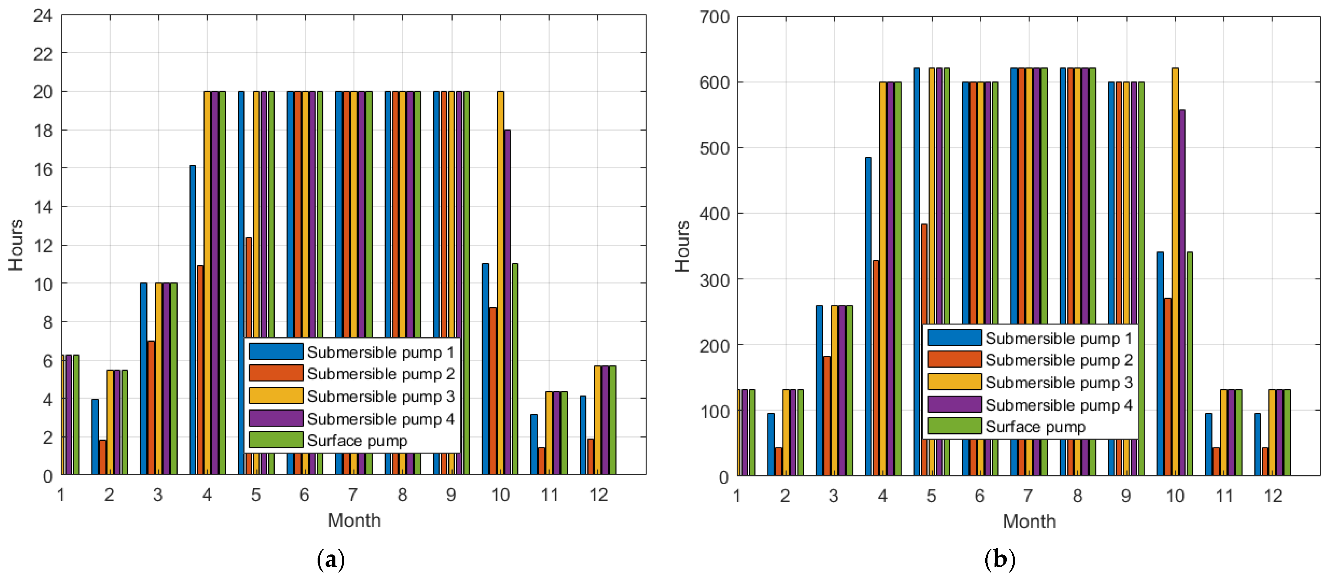
Figure 8 presents the operating period of each pump on a representative day of every month, shown in Figure 8a, and during the entire month, shown in Figure 8b, after the one-year simulation. The representative day of every month refers to a day that represents the average of the considered characteristics (operating hours in Figure 8) of the operational days of every month.
Figure 8a confirms the correct operation of the proposed control strategy, respecting the boundaries of the contract with the energy provider. During the most demanding irrigation months (June, July, August and September), the maximum operating period of any pump does not exceed 20 hours, including only the standard (7:00–18:00) and off-peak (22:00–7:00) periods, because no power is contracted during the four hours of the peak period (18:00–22:00). From Figure 8b, it can be seen that, outside the irrigation campaign (November, December, January and February), the customer uses the system one-quarter of the time that it is used during the most demanding months of the irrigation campaign (June, July, August and September).
Figure 9 depicts the energy consumption of each pump during a representative day of every month, shown in Figure 9a, and during the entire month, in Figure 9b, for the one-year simulation, compared to the experimental data (data obtained from the electricity bills in 2021). As seen in Figure 9, the maximum energy consumption during the irrigation campaign reaches 2.4 MWh/day (Figure 9a) and 75 MWh/month (Figure 9b).
The result for the energy consumption of the irrigation system based on the one-year simulation, depicted in Figure 9, is validated by the experimental energy consumption in 2021 obtained from the electricity bills, presented in Table 3.
Figure 10 depicts the absorbed power from the electrical grid by the entire irrigation (all the pumps) system during the representative day of each month based on the one-year simulation. Figure 9 confirms, again, the correct operation of the proposed control strategy, which respects the contract boundaries, as there is no energy consumption during the peak hours (pink colored area in Figure 10). In Figure 10, it can be seen that during the simulation, the proposed control strategy behaves in the same ways as the real system (confirmed by the experimental data from Table 3) because, outside the irrigation campaign (November, December, January and February), the system operates only during the standard period and, during the most demanding months of the irrigation campaign (June, July, August and September), all the pumps work for almost 20 h.
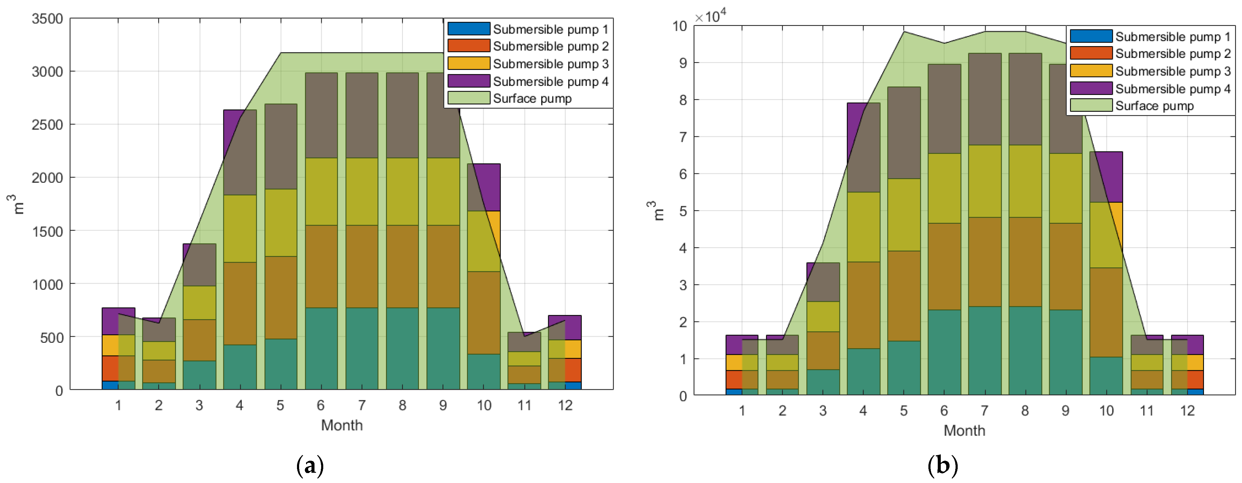
Figure 11 depicts the one-year simulation of the volume pumped by each pump during the representative day of every month, shown in Figure 11a, and during the entire month, in Figure 11b. As can be seen in Figure 11, slightly more of the volume of the water collected by the submersible pump (692,000 m3) is distributed by the surface pump (717,000 m3) to the irrigation network, distributing even more, because the simulation started with the water storage unit being full (25,000 m3), leaving it empty at the end of the year. This was an input restriction affecting the simulation. The simulation results are very close to the experimental data obtained during the 2021 irrigation campaign, where, according to the irrigation flow counter, a total volume of 700,000 m3 was pumped into the irrigation network. The 2021 irrigation campaign started and ended with the water storage unit full.
Figure 12 presents the water flow distributed to the irrigation system by the surface pump on the representative day of every month during the one-year simulation. Figure 12 confirms the performance of the proposed control strategy, operating as desired during the entire year, without the need for external adjustment. In the same figure, during the peak hours, the system does not irrigate the field, and outside the irrigation campaign, the irrigation is significantly reduced (about a quarter) compared to the most demanding months.
In order to validate the performance of the proposed control strategy with respect to another intermittent and fluctuating power source, the response of the proposed control strategy was simulated using the proposed model, considering the power produced by a 164 kW photovoltaic generator at the site location. Due to space restrictions in this paper, for the second simulation, we present the analysis of only two performance indicators (the most important ones): the energy produced by the photovoltaic generator and the pumps’ water flow discharge.
The power produced by the 164 kW photovoltaic generator during the representative day of each month is presented in Figure 13. In this case, the representative day of each month refers to a day that represents the average of the considered characteristics (energy produced in this Figure 13) of each month. As can be seen from the shape of the curves, the structure of the photovoltaic generator consists of one axis with n-S trackers that track the sun from east to west and uses a backtracking algorithm to reduce the impact created by the shadow of the neighboring trackers.
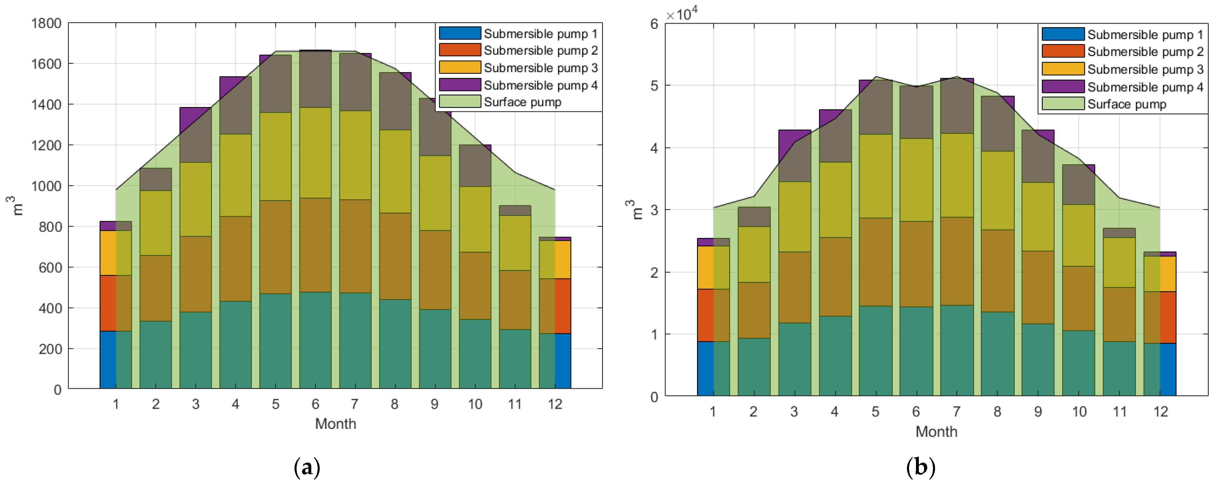
Similar to the simulation considering a power grid with three price periods as a fluctuating and intermittent power source, the simulation considering the photovoltaic generator confirms the good performance of the proposed control strategy in operating a pumping system with water storage powered by a fluctuating and intermittent power source. Figure 14 presents the volume pumped by each pump during the representative day of every month, shown in Figure 14a, and during every month, in Figure 14b, and it shows that by integrating a 164 kW photovoltaic generator into the actual system, except for the most demanding months of the irrigation campaign, all the energy necessary for a similar irrigation can be ensured by a 164 kW photovoltaic generator. During the most demanding months, only half of the energy required by the irrigation system can be ensured by the 164 kW photovoltaic generator.
Overall, based on the performance indicators of the two simulations, it can be concluded that:
  • Of all the simulation performance indicators (operating period, absorbed power, energy consumption, pumping water flow and volume), two of them were validated by the experimental data. The monthly energy consumption was validated by the energy consumption from the monthly electricity bills during the 2021 irrigation campaign. Additionally, the water volume at the end of the one-year simulation was validated by the irrigation water volume displayed on the flow counter at the end of the same irrigation campaign.
  • Using an intermittent and fluctuating power source, the presented control strategy, in addition to respecting all the boundaries and conditions imposed, performs very well, sometimes naturally (by a photovoltaic generator or a wind electrical generator) and sometimes economically (by an electricity source with various price periods), leading to an efficient energy management without sacrificing the operation and lifetime of the plant.
  • The proposed control strategy managed the water storage (ensuring stable and continuous irrigation, especially during the irrigation campaign) with high efficiency and respected the economic restrictions imposed by the user. It should be mentioned that, during the irrigation campaign, the proposed control strategy used the irrigation system’s capabilities to the maximum, while outside this campaign, it only used the necessary capacity.
  • In the simulation where the photovoltaic generator powered the multi-pump system with water storage, it was found that a 164 kW photovoltaic generator can ensure all the energy necessary for a similar irrigation campaign, except during the most demanding months of the irrigation campaign (June, July, August and September), where only half of the energy required by the irrigation system can be ensured by the photovoltaic generator.
  • Although the proposed control strategy was tested only in the case of pumping systems powered by an electrical grid with various price periods or by photovoltaic generators, it can be assumed that it would also work for those powered by wind electrical generators (due to their slower dynamics compared to photovoltaic generators or power grids).

5. Conclusions

The proposed modelling and control strategy operates a multi-pump system with water storage powered by any fluctuating and intermittent power source, such as a power grid with various price periods (with three price periods being considered in this paper: standard, peak and off-peak), a photovoltaic generator or even a wind electrical generator. A real irrigation system was considered in this paper, but the solution can be applied to any water supply and distribution system in the civil/industrial or agricultural industry.
The multi-pump system model and the proposed control strategy were validated through an in-depth analysis of the simulation performance indicators of the considered irrigation system, powered by an electrical grid with three price periods in the first simulation and by a photovoltaic generator in the second simulation. For the first simulation, two performance indicators (the monthly energy consumption and water volume discharged into the irrigation system) were validated by the experimental data. From the second simulation, it was found that a 164 kW photovoltaic generator can ensure all the energy necessary for a similar irrigation campaign, except during the most demanding months of the irrigation campaign, where only half of the energy required by the irrigation system can be ensured by the photovoltaic generator.
The novelty of this work consists of the proposed control strategy, which demonstrated, through the simulations results (part of the results were also confirmed experimentally), a good performance in operating a multi-pump system with water storage powered by any fluctuant and intermittent power source.
In addition to the main contribution offered through the proposed control strategy, this work also contributes, together with the proposed model and the simulation methodology, an evaluation of the technical and economic feasibility of integrating any fluctuating and intermittent power source into a multi-pump system with water storage. The proposed modelling, control strategy and simulation methodology can benefit those working on all the multi-pump systems with water storage in terms of the identification, planning, evaluation and negotiation of new energy supply contracts for their powering.
Finally, it can be mentioned that, in future work, more advanced control strategies, compared to that the presented here, can be implemented, such as robust control, model predictive control, fuzzy logic control, adaptive control or neural network-based control, etc.

Author Contributions

Conceptualization, D.B.; methodology, D.B.; validation, D.B., O.P., I.F., F.D. and C.V.; formal analysis, D.B., O.P., I.F., F.D. and C.V.; investigation, D.B., O.P., I.F., F.D. and C.V.; resources, D.B., O.P., I.F., F.D. and C.V.; data curation, D.B., O.P., I.F., F.D. and C.V.; writing—original draft preparation, D.B.; writing—review and editing, O.P., I.F., F.D. and C.V.; visualization, D.B., O.P., I.F., F.D. and C.V.; supervision, O.P., I.F., F.D. and C.V.; project administration, D.B.; funding acquisition, I.F. All authors have read and agreed to the published version of the manuscript.

Funding

This research was funded by the EEA and Norway Grants under grant No. 2022/337338, entitled: Design and Development of an Energy Efficiency Management and Control System with Cost-Effective Solutions for Residential and Educational Buildings.

Data Availability Statement

Not applicable.

Conflicts of Interest

The authors declare no conflict of interest.

Abbreviations

List of denotations, meanings and units:
H0Nominal pumping head, m;
HgStatic head, m;
kHead loss coefficient, h/m2;
Q0Nominal pumping flow rate, m3/h;
Phid0Nominal pump’s hydraulic power, W;
ρWater density, Kg/m3;
gGravitational acceleration, m/s2;
VpoolWater pool capacity, m3;
Vpool.outWater volume extracted from the pool by the surface pump, m3;
Vpool.inWater volume discharged into the pool by the submersible pumps, m3;
AHead–flow 1st coefficient, m;
BHead–flow 2nd coefficient, h/m2;
CHead–flow 3rd coefficient, h/m5;
DEfficiency–flow 1st coefficient, 1/m2;
EEfficiency–flow 2nd coefficient, 1/m5;
η0Nominal efficiency of the pump, -;
ωPump’s operating speed, rad/s;
ω0Pump’s nominal speed, rad/s;
αDenotes the ratio between the pump’s nominal and operating speeds, -;
Ppump0Nominal mechanical (rotational) power required by the pump, W;
PpumpOperating mechanical (rotational) power required by the pump, W;
HOperating pumping head, m;
QOperating pumping flow rate, m3/h;
GPump geometry, m2;
Q(ω)Pump discharge according to the pump speed variation, m3/h;
ηOperating efficiency of the pump, -;
TpumpPump torque, Nm;
IpumpPump moment of inertia, Kg m2;
v s s The stator voltage vector reference to the stator, V;
i s s The stator current vector reference to the stator, A;
ψ r s The rotor flux vector reference to the stator, Vm;
LmMagnetizing inductance, H;
LsStator inductance, H;
LrRotor inductance, H;
TemElectromagnetic torque of the induction motor, Nm;
PIMInput power of the induction motor/output power, W;
pmotorInduction motor’s number of pole pairs, -;
k0 No-load inverter losses, -;
k1 Linear inverter losses, -;
k2 Joule inverter losses, -;
PdrivenominalNominal power of the induction motor drive, W;
PdriveinputInput power of the induction motor drive, W;
ηdriveEfficiency of the induction motor drive, %;
ηfilterEfficiency of the DV/DT filter, %;
ηcablesThe efficiency after the loss due to the voltage drop in the cables, %;
vds and vqsThe stator three-phase AC voltage commands transformed in the synchronous (dq) reference frame, V;
vαs and vβsThe stator three-phase AC voltage commands transformed in the stationary (αβ) reference frame, V;
vas, vbs, vcsThe stator three-phase AC voltages, V;
ias, ibs, icsThe stator three-phase AC currents, A;
iα and iβThe stator three-phase AC currents expressed in stationary (αβ) reference frame, A;
Sa, Sb, ScThe pulse-width modulation switching commands (orders), -;
Tdq.αβTransformation from synchronous (dq) reference frame into stationary (αβ) reference frame, -;
Tabc.αβTransformation from three-phase (abc) complex space vector into stationary (αβ) reference frame, -;
Tαβ.dqTransformation from stationary (αβ) reference frame into synchronous (dq) reference frame, -;
Tαβ.abcTransformation from stationary (αβ) reference frame into three-phase (abc) complex space vector, -;
ids*Reference of the d-axis (real component) current loop, A;
idsThe output of the d-axis (real component) current loop, A;
iqs*The reference of the q-axis (imaginary component) current loop, A;
iqsThe output of the q-axis (imaginary component) current loop, A;
kp1Proportional gain of the d- and q-axis current systems, -;
ki1Integral gain of the d- and q-axis current systems, -;
ωn1The first natural frequency of the d- and q-axis current systems, Hz;
ξ1The damping factor of the d- and q-axis current systems, Ns/m;
fmInduction motor electrical frequency, Hz;
fm*Induction motor electrical frequency reference, Hz;
kp2Proportional gain of the driving shaft speed controller, -;
ki2Integral gain of the driving shaft speed controller, -;
ωn2The first natural frequency of the driving shaft system, Hz;
ξ2The damping factor of the driving shaft system, Ns/m;
τrInduction motor’s rotor time constant, s;
kp3Proportional gain of the rotor flux controller, -;
ki3Integral gain of the driving rotor flux controller, -;
ωn3The first natural frequency of the rotor flux estimator, Hz;
ξ3The damping factor of the rotor flux estimator, Ns/m.

Appendix A

Table A1 presents the technical specifications of the submersible [24] and surface [25] pumps.
Table A1. Pumps’ technical specifications.
PropertiesSubmersible PumpSurface PumpSymbolUnit
ManufacturerCaprariDutchi Motors--
TypeE6P35/14MDM1 225M4--
Pump number1234---
Operating Flow38.5238.8834.6840150–170Qm3/h
Maximum flow41414141-Qmaxm3/h
Consumer pressure11.21.21.53.7Hgconsbar
Well Dynamic head10098100105-Hgwellmca
Water level variation0101-ΔHgmca
Pipe diameter0.110.110.110.11-Dpipem
Measured voltage400400400400400VV
Measured current3937.8364059IC
Measured Power factor0.80.80.80.80.87Cos φ-
Absorbed power21.61620.9519.95322.1735.562PkW
Head–flow 1st coefficient187.124441.2583Am
Head–flow 2nd coefficient0.66710.0891Bh/m2
Head–flow 3rd coefficient−0.0577−0.0005Ch/m5
Efficiency–flow 1st coefficient4.38120.8306D1/m2
Efficiency–flow 2nd coefficient−0.0628−0.0022E1/m5
Table A2 presents the technical specifications of the induction motors that drive the submersible [24] and surface [25] pumps.
Table A2. Induction motors’ technical specifications.
Technical PropertiesSubmersible Pump
Induction Motor
Surface Pump
Induction Motor
SymbolUnit
ManufacturerCaprariDutchi Motors--
TypeMAC625A-8VM301852121-V--
Nominal Power18.534PIM0kW
Nominal Efficiency83%94.2%ηIM0%
Nominal Frequency5050fIMHz
Nominal Voltage400400VIMV
Nominal Current40.281.1IIMA
Number of poles24Poles-
Rotor synchronous speed30001500ωsrpm
Rotor nominal speed28751480ω0rpm
Rotor operating speedVariableVariableωrpm
Power factor0.80.85cos φ-
Table A3 presents the technical specifications of the variable frequency drive (VFD) [36].
Table A3. Variable frequency drive technical specifications.
Technical PropertiesVariable Frequency DriveSymbolUnit
ManufacturerNidec Control Techniques--
TypeF300--
Maximum DC voltage980VmaxVFDdcVdc
MMP DC voltage range540–830VVFDdcVdc
AC rated power45PVFDkW
AC rated voltage400VVFDacVac
AC rated frequency50fVFDA
AC maximum continuous current94IVFDA
No-load inverter losses0.0115k0-
Linear inverter losses0.0015k1-
Joule inverter losses0.0438k2-

References

  1. Lai, Z.; Li, Q.; Zhao, A.; Zhou, W.; Xu, H.; Wu, D. Improving Reliability of Pumps in Parallel Pump Systems Using Particle Swam Optimization Approach. IEEE Access 2020, 8, 58427–58434. [Google Scholar] [CrossRef]
  2. Arun Shankar, V.K.; Umashankar, S.; Paramasivam, S.; Hanigovszki, N. An Energy Efficient Control Algorithm for Parallel Pumping Industrial Motor Drives System. In Proceedings of the IEEE International Conference on Power Electronics, Drives and Energy Systems (PEDES) 2018, Chennai, India, 18–21 December 2018; pp. 1–6. [Google Scholar] [CrossRef]
  3. European Parliament; European Council. Directive 2005/32/EC 2005 Of the European Parliament and of the Council of 6 July 2005 establishing a framework for the setting of ecodesign requirements for energy-using products and amending Council Directive 92/42/EEC and Directives 96/57/EC and 2000/55/EC of the European Parliament and of the Council. Off. J. Eur. 2005. [Google Scholar]
  4. Olszewski, P. Genetic optimization and experimental verification of complex parallel pumping station with centrifugal pumps. Appl. Energy 2016, 178, 527–539. [Google Scholar] [CrossRef]
  5. Qiang, Z.; Li, G.; Rui, Z. Integrated model of water pump and electric motor based on BP neural network. In Proceedings of the 2015 IEEE 10th Conference on Industrial Electronics and Applications (ICIEA), Auckland, New Zealand, 15–17 June 2015; pp. 1449–1452. [Google Scholar] [CrossRef]
  6. Xiang, H.; Wu, J.; Chang, X.; Wang, D.; Ji, L. Study on optimal scheduling pump group based on parallel H-Q characteristics and pipe characteristics. In Proceedings of the 2019 Chinese Control Conference (CCC), Guangzhou, China, 27–30 July 2019; pp. 7161–7165. [Google Scholar] [CrossRef]
  7. Olszewski, P.; Arafeh, J. Parametric analysis of pumping station with parallel-configured centrifugal pumps towards self-learning applications. Appl. Energy 2018, 231, 1146–1158. [Google Scholar] [CrossRef]
  8. Yang, Z.; Soleiman, K.; Løhndorf, B. Energy Efficient Pump Control for an Offshore Oil Processing System. IFAC Proc. 2018, 45, 257–262. [Google Scholar] [CrossRef] [Green Version]
  9. Bordeașu, D. Study on the implementation of an alternative solution to the current irrigation system. In Proceedings of the ErgoWork 2022 International Conference on Ergonomics and Workplace Management, Timișoara, Romania, 16 June 2022. [Google Scholar]
  10. Bordeașu, D.; Proștean, O.; Vașar, C.; Debeș, A. Load Comparison Between Two Controlling Strategies for Wind Energy Conversion System Power-Boosting. In Proceedings of the IEEE 16th International Symposium on Applied Computational Intelligence and Informatics (SACI 2022), Timișoara, Romania, 25 May 2022. [Google Scholar]
  11. Abdelsalam, A.; Basma, M.; Essam, R. Power Saving of Multi Pump-Motor Systems Using Variable Speed Drives. In Proceedings of the 2018 Twentieth International Middle East Power Systems Conference (MEPCON), Cairo, Egypt, 18–20 December 2018; pp. 839–844. [Google Scholar] [CrossRef]
  12. Bakman, I.; Gevorkov, L.; Vodovozov, V. Efficiency Control for Adjustment of Number of Working Pumps in Multi-pump System. In Proceedings of the 2015 9th International Conference on Compatibility and Power Electronics (CPE), Costa da Caparica, Portugal, 24–26 June 2015. [Google Scholar]
  13. Bordeasu, I.; Micu, L.M.; Oanca, O.V.; Pugna, A.; Bordeasu, C.; Popoviciu, M.O.; Bordeasu, D. Laser beam treatment effect on AMPCO M4 bronze cavitation erosion resistance. IOP Conf. Ser. Mater. Sci. Eng. 2015, 85, 10. [Google Scholar] [CrossRef] [Green Version]
  14. Micu, L.M.; Bordeasu, I.; Popoviciu, M.O.; Popescu, M.; Bordeasu, D.; Salcianu, L.C. Influence of volumic heat treatments upon cavitation erosion resistance of duplex X2CrNiMoN 22-5-3 stainless steels. IOP Conf. Ser. Mater. Sci. Eng. 2015, 85, 012019. [Google Scholar] [CrossRef]
  15. Rishel, J.B. Water Pumps and Pumping Systems, 1st ed.; MC Graw. Hill: New York, NY, USA, 2002; ISBN 10:0071374914/ISBN 13:9780071374910. [Google Scholar]
  16. Bakman, I.; Gevorkov, L.; Vodovozov, V. Predictive Control of a Variable-Speed Multi-Pump Motor Drive. In Proceedings of the 2014 IEEE 23rd International Symposium on Industrial Electronics (ISIE), Istanbul, Turkey, 1–4 June 2014. [Google Scholar]
  17. Bakman, I.; Gevorkov, L. Speed Control Strategy Selection for Multi Pump Systems. In Proceedings of the 56th International Scientific Conference on Power Electrical Engineering of Riga Techanical University, Riga, Latvia, 14–14 October 2015. [Google Scholar]
  18. Vodovozov, V.; Lehtla, T.; Bakman, I.; Raud, Z.; Gevorkov, L. Energy-efficient predictive control of centrifugal multi-pump stations. In Proceedings of the 2016 Electric Power Quality and Supply Reliability (PQ), Tallinn, Estonia, 29–31 August 2016; pp. 233–238. [Google Scholar] [CrossRef]
  19. Vodovozov, V.; Raud, Z. Predictive Control of Multi-Pump Stations with Variable-Speed Drives. IET Electr. Power Appl. 2017, 11, 911–917. [Google Scholar] [CrossRef]
  20. Ursachi, A.; Bordeasu, D. Smart Grid Simulator. Int. J. Electr. Comput. Eng. 2014, 8, 542–545. [Google Scholar]
  21. Elsisi, M.; Tran, M.-Q.; Hasanien, H.M.; Turky, R.A.; Albalawi, F.; Ghoneim, S.S.M. Robust Model Predictive Control Paradigm for Automatic Voltage Regulators against Uncertainty Based on Optimization Algorithms. Mathematics 2021, 9, 2885. [Google Scholar] [CrossRef]
  22. Tian, M.-W.; Yan, S.-R.; Liu, J.; Alattas, K.A.; Mohammadzadeh, A.; Vu, M.T. A New Type-3 Fuzzy Logic Approach for Chaotic Systems: Robust Learning Algorithm. Mathematics 2022, 10, 2594. [Google Scholar] [CrossRef]
  23. Solar Irrigation in a 95 ha Citrus Plantation. Available online: https://bombeatec.com/en/casos-de-exito/solar-irrigation-in-a-96ha-citrus-plantation/ (accessed on 5 June 2022).
  24. Caprari 2019 Submersible Electric Pump E6P35/14M+MAC625A-8V Technical Data Sheet. Available online: https://ipump.caprarinet.net/ (accessed on 5 June 2022).
  25. Dutchi Motors Series DM1 Technical Data Sheet. Available online: https://vecgroup.com/assets/pdf/DM1.pdf (accessed on 5 June 2022).
  26. Bordeașu, D.; Proștean, O.; Hatiegan, C. Contributions to Modeling, Simulation and Controlling of a Pumping System Powered by a Wind Energy Conversion System. Energies 2021, 14, 7696. [Google Scholar] [CrossRef]
  27. Predescu, A.; Truică, C.-O.; Apostol, E.-S.; Mocanu, M.; Lupu, C. An Advanced Learning-Based Multiple Model Control Supervisor for Pumping Stations in a Smart Water Distribution System. Mathematics 2020, 8, 887. [Google Scholar] [CrossRef]
  28. Bărglăzan, M.; Velescu, C.; Miloş, T.; Manea, A.; Dobândă, E.; Stroiţă, C. Hydrodynamic Transmission Operating with Two-phase Flow. Comput. Methods Multiph. Flow IV WIT Trans. Eng. Sci. 2007, 56, 369. [Google Scholar]
  29. Oshurbekov, S.; Kazakbaev, V.; Prakht, V.; Dmitrievskii, V. Improving Reliability and Energy Efficiency of Three Parallel Pumps by Selecting Trade-Off Operating Points. Mathematics 2021, 9, 1297. [Google Scholar] [CrossRef]
  30. White, F.M. Chapter 11 Turbomachinery. In Fluid Mechanics, 7th ed.; McGraw-Hill: New York, NY, USA, 2011. [Google Scholar]
  31. Sârbu, I.; Borza, I. Energetic optimization of water pumping in distribution systems. Period. Polytech. Ser. Mech. Eng. 1998, 42, 141–152. [Google Scholar]
  32. Thorley, A.R.D. Fluid Transients in Pipeline Systems; D. & L. George Ltd.: Herts, UK, 1991. [Google Scholar]
  33. Sul, S. Control of Electric Machine Drive Systems; John Wiley & Sons: Hoboken, NJ, USA, 2011; pp. 291–294. [Google Scholar]
  34. Haţiegan, C.; Chioncel, C.P.; Răduca, E.; Popescu, C.; Pădureanu, I.; Jurcu, M.R.; Bordeaşu, D.; Trocaru, S.; Dilertea, F.; Bădescu, O. Determining the operating performance through electrical measurements of a hydro generator. IOP Conf. Ser. Mater. Sci. Eng. 2017, 163, 012031. [Google Scholar] [CrossRef] [Green Version]
  35. Nidec Control Techniques Digistart D3 23 A-1600A 200 V-690 V; Nidec Control Techniques Ltd.: Newtown, UK, 2017; p. 324.
  36. Nidec Control Techniques Powerdrive F300; Nidec Control Techniques Ltd.: Newtown, UK, 2017.
  37. Muñoz, J.; Martínez-Moreno, F.; Lorenzo, E. On-site characterisation and energy efficiency of grid-connected PV inverters. Prog. Photovolt. Res. Appl. 2011, 19, 192–201. [Google Scholar] [CrossRef]
  38. Abad, G. Power Electronics and Electric Drives for Traction Applications; John Wiley & Sons: Chichester, UK, 2017; pp. 37–98, 149–185. [Google Scholar]
  39. Abu-Rub, H.; Malinowski, M.; Al-Haddad, K. Power Electronics for Renewable Energy Systems, Transportation and Industrial Applications; IEEE Press and John Wiley & Sons Ltd.: Chichester, UK, 2014; pp. 277–356. [Google Scholar]
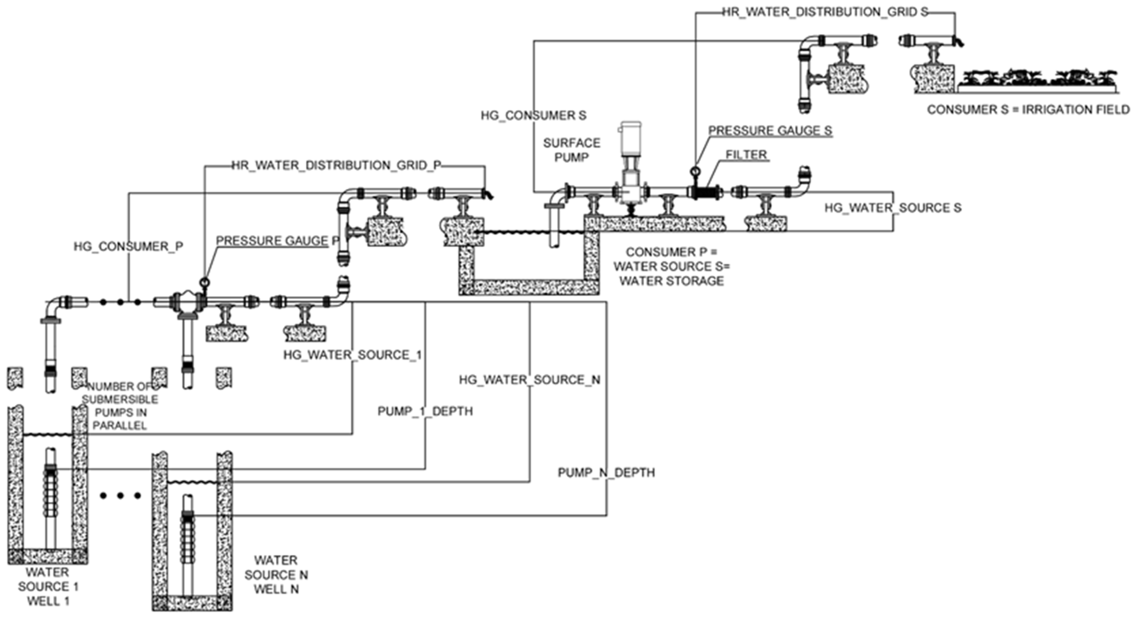
Figure 1. Multi-pump system layout.
Mathematics 10 04019 g001
Figure 2. Pump head–flow HQ curve at different speeds: (a) submersible pumps; (b) surface pump.
Mathematics 10 04019 g002
Figure 3. The η-Q curve at different speeds: (a) submersible pump; (b) surface pump.
Mathematics 10 04019 g003
Figure 4. Iso-efficiency curve, together with each pump characteristic curve: (a) submersible pumps; (b) surface pumps.
Mathematics 10 04019 g004
Figure 5. Structure of the multi-pump control system.
Mathematics 10 04019 g005
Figure 6. General system controller flow chart.
Mathematics 10 04019 g006
Figure 7. Induction motor control loops for one single pump.
Mathematics 10 04019 g007
Figure 8. Operating hours of each pump: (a) on the representative day of every month; (b) every month.
Mathematics 10 04019 g008
Figure 9. Energy consumption of each pump: (a) on the representative day of every month; (b) every month (simulation vs. experiment).
Mathematics 10 04019 g009
Figure 10. Power absorbed from the electrical grid by the system during the representative day of each month.
Mathematics 10 04019 g010
Figure 11. Volume pumped by each pump: (a) on the representative day of every month; (b) every month.
Mathematics 10 04019 g011
Figure 12. Irrigation water flow on the representative day of each month.
Mathematics 10 04019 g012
Figure 13. Energy produced by a 164 kW photovoltaic generator at the site location during the representative day of each month.
Mathematics 10 04019 g013
Figure 14. Volume pumped by each pump using a 164 kW photovoltaic generator: (a) on the representative day of every month; (b) every month.
Mathematics 10 04019 g014
Table 1. Experimental data vs. model validation data.
PumpMeasured Power Consumption (kW)Simulated Power Consumption (kW)Power Error (%)Measured
Current
Consumption (A)
Simulated
Current
Consumption (A)
Current Error (%)
Submersible pump 121.61620.8843.38643937.683.3846
Submersible pump 220.9521.528−2.758937.838.8412−2.7545
Submersible pump 319.95320.858−4.53573637.6323−4.5342
Submersible pump 422.1721.2224.2764038.28914.2773
Surface pump35.56235.04981.44035958.14941.4417
Table 2. Monthly percentage of the total operating period.
MonthSubmersible Pump 1Submersible Pump 2Submersible Pump 3Submersible Pump 4
January10%30%30%30%
February10%30%30%30%
March10%30%30%30%
April10%30%30%30%
May10%30%30%30%
Jun25%25%25%25%
July25%25%25%25%
August19%27%27%27%
September25%25%25%25%
October10%30%30%30%
November10%30%30%30%
December10%30%30%30%
Table 3. Irrigation system monthly energy consumption during 2021 in kWh (experimental data).
MonthStandard Hours kWh
7:00–18:00
Peak Hours
kWh
18:00–22:00
Off-Peak Hours kWh
22:00–7:00
Total Energy kWhOperational Days/Month
January12,5810012,58121
February12,5810012,58124
March27,1540242229,57626
April33,789028,35962,14830
May35,890033,55169,44131
Jun39,683032,46872,15230
July41,006033,55174,55731
August41,006033,55174,55731
September39,683032,46872,15230
October33,635016,00449,63931
November12,5810012,58130
December12,5810012,58123
Publisher’s Note: MDPI stays neutral with regard to jurisdictional claims in published maps and institutional affiliations.