
Finite-Control-Set Model Predictive Control for Low-Voltage-Ride-Through Enhancement of PMSG Based Wind Energy Grid Connection Systems
 ,
,  , ,
, ,  , and
, and 
Abstract
:1. Introduction
- An FCS-MPC scheme is utilized to enhance the LVRT operation of a PMSG-based grid connected wind generation system.
- Optimized switching states are selected by proposed predictive model to achieve reduced cross-coupling errors of active and reactive power predictions.
- Priority-based weighting factors are tuned for faster performance of the controller for P and Q power injection under various grid scenarios.
- DC-link overvoltage oscillation mitigation with better reference tracking.
- Lyapunove’s stability criterion and parameter robustness analysis have been performed.
- Improved implementation of proposed scheme under both symmetrical and asymmetrical grid faults in accordance with recommended grid codes.
- Dynamic performance analysis and comparison of the proposed FCS-MPC method with classical PI controller.
- Experimental verification of the simulated results.
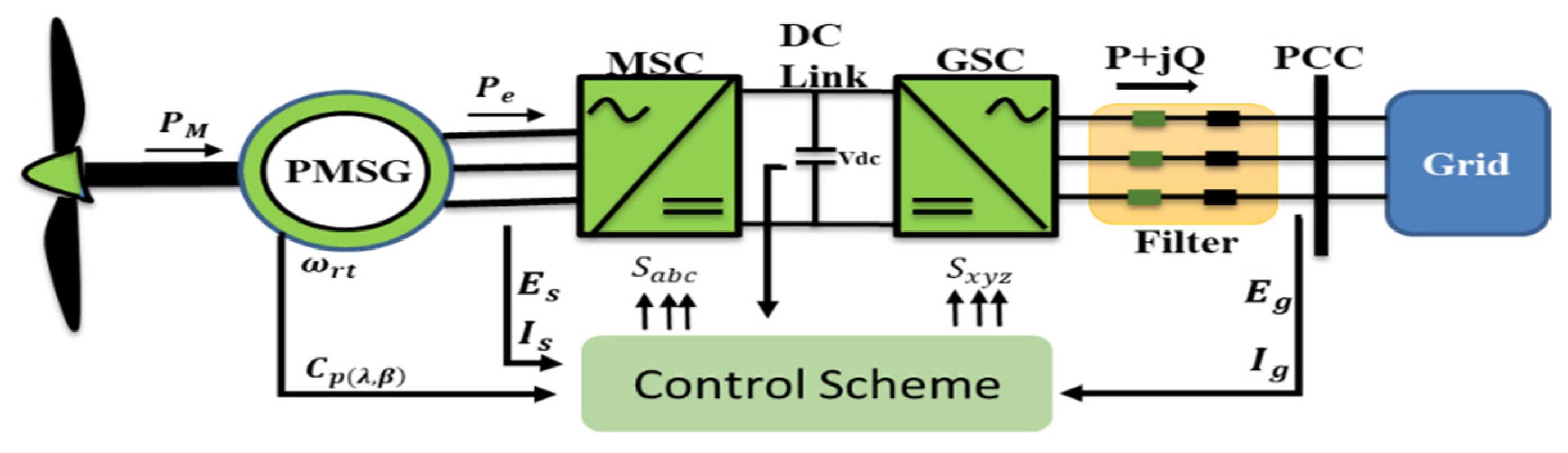
2. Grid Connected Wind Turbine System
2.1. Wind-Turbine Modeling
2.2. Multiphase PMSG Modeling
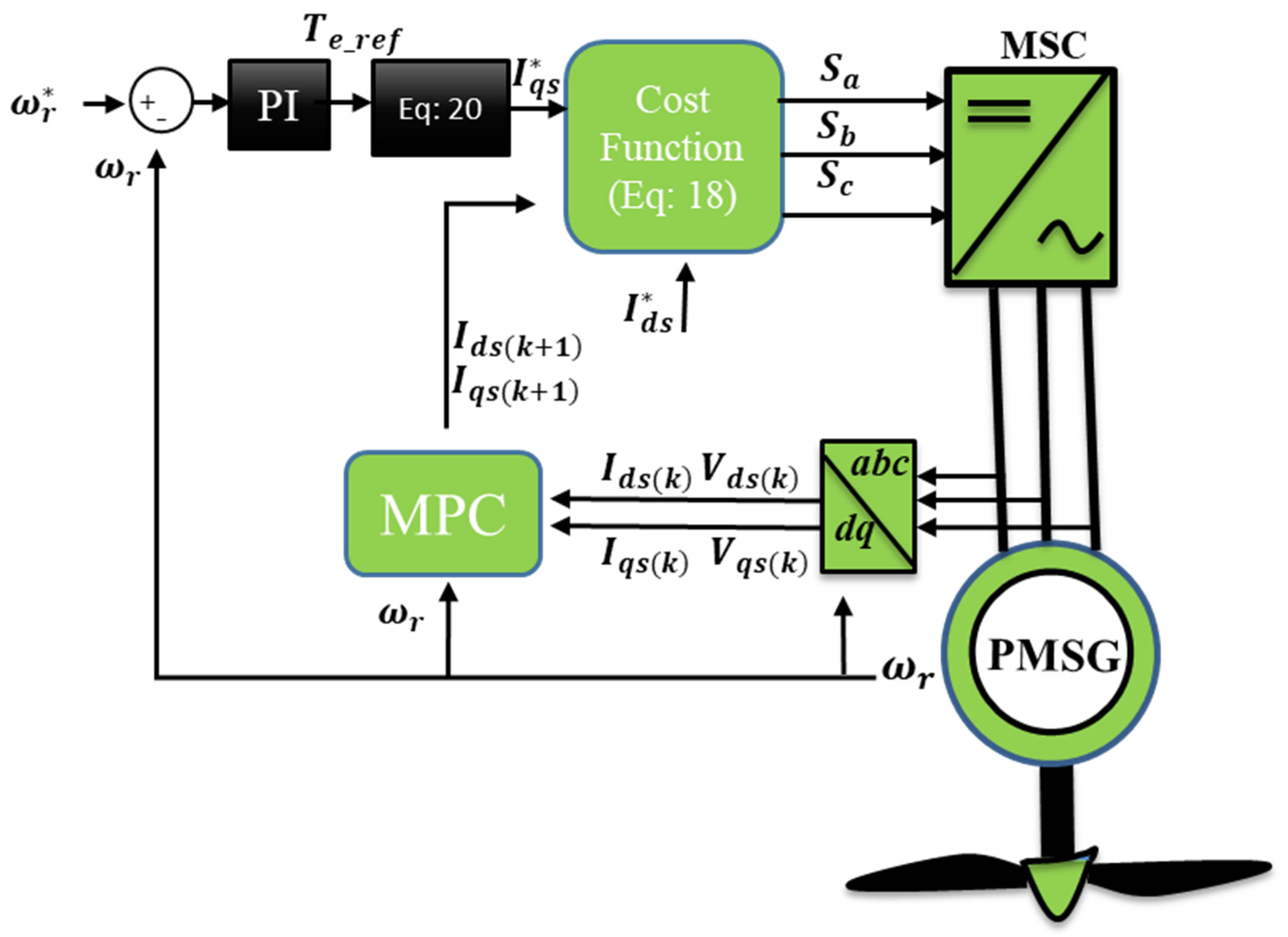
3. FCS-MPC Scheme in Grid Connected Inverters
3.1. Machine Side Converter (MSC) Control
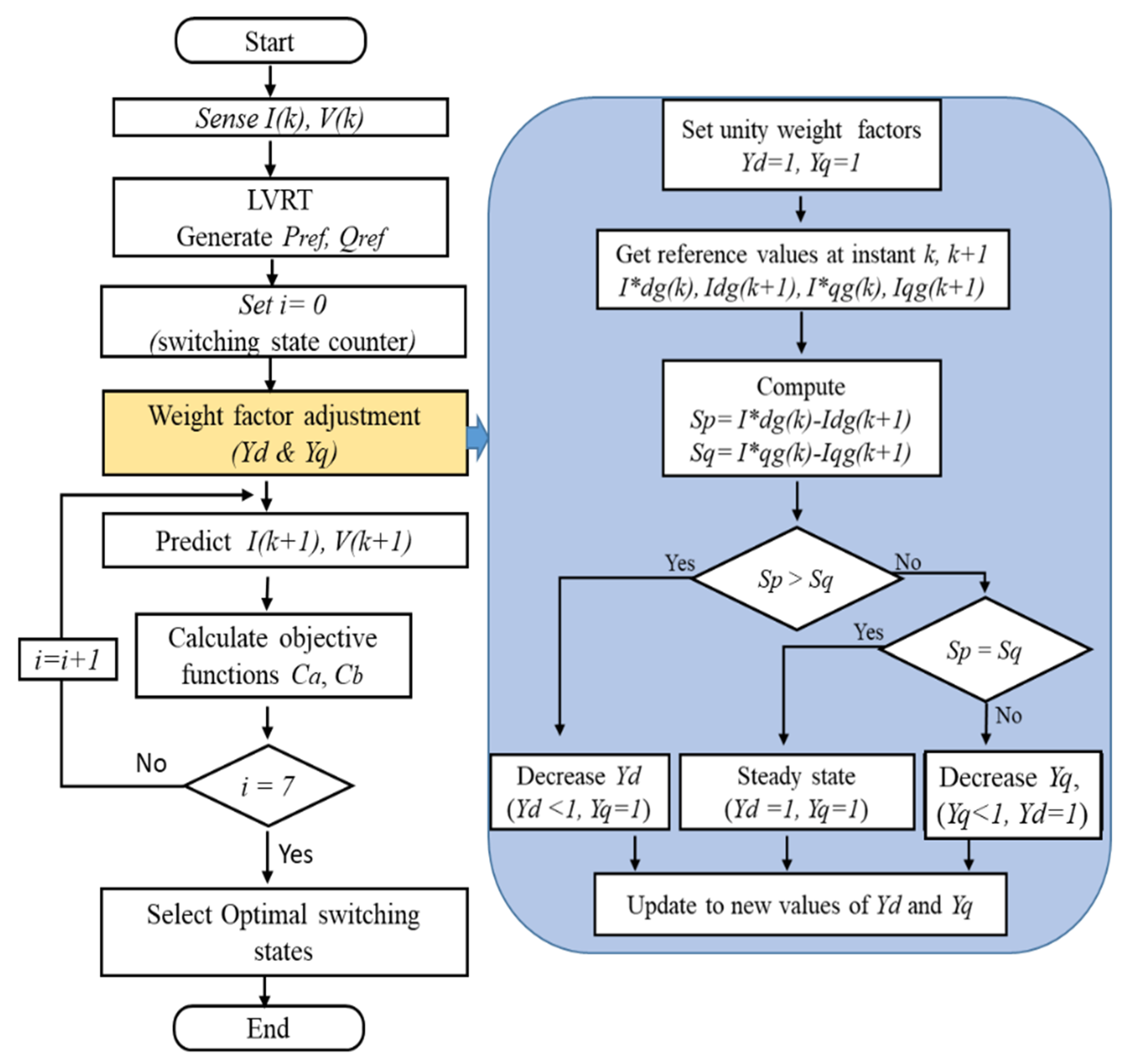
3.2. Grid Side Converter (GSC) Control with FCS-MPC
3.3. Dynamic Weight Factors (γd, γq) Modification
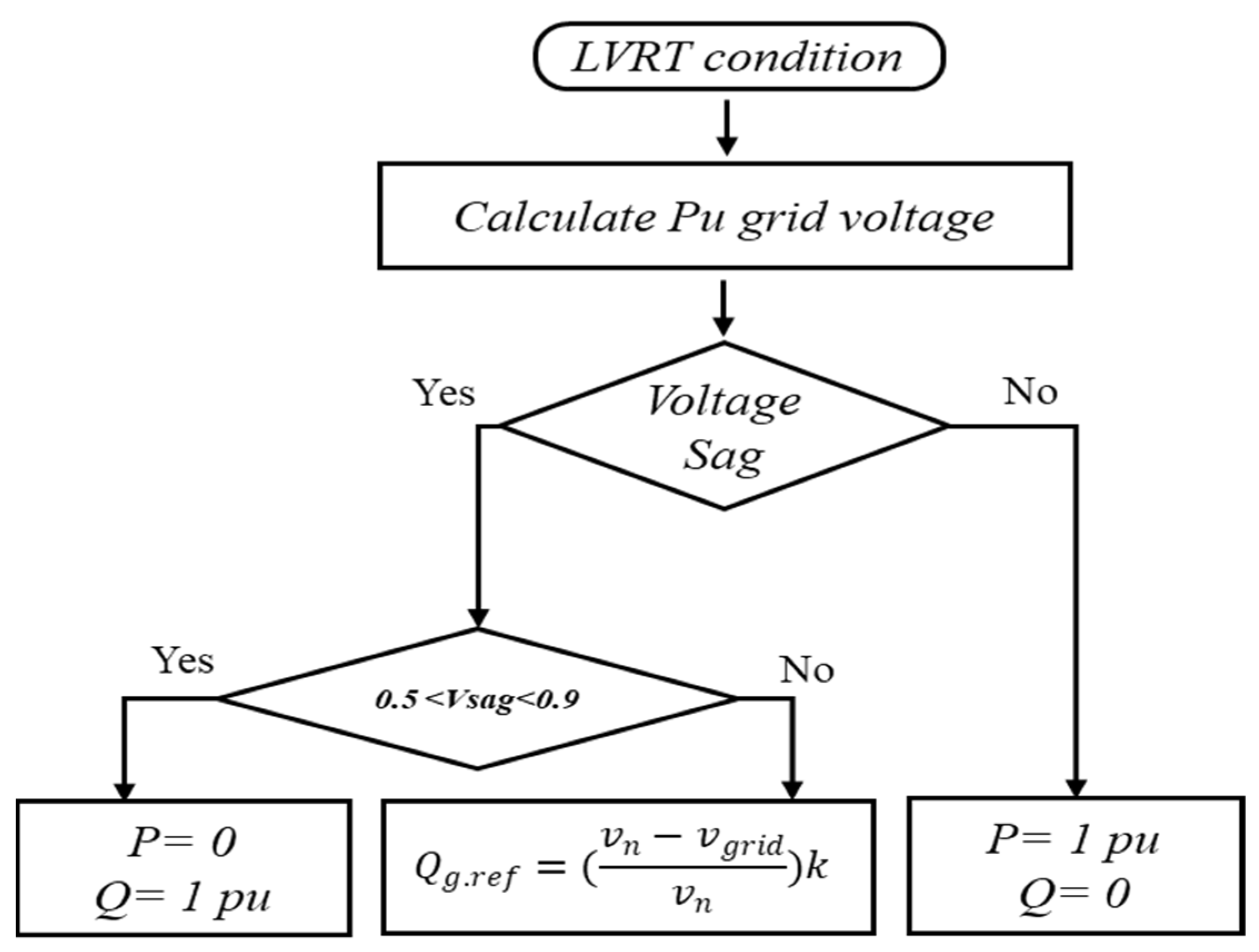
3.4. LVRT Requirements
3.5. Stability Analysis
4. Simulation Results and Discussions
- (a)
- P and Q transient performance with fixed and variable WFs.
- (b)
- LVRT performance under symmetrical and asymmetrical faults on the grid.
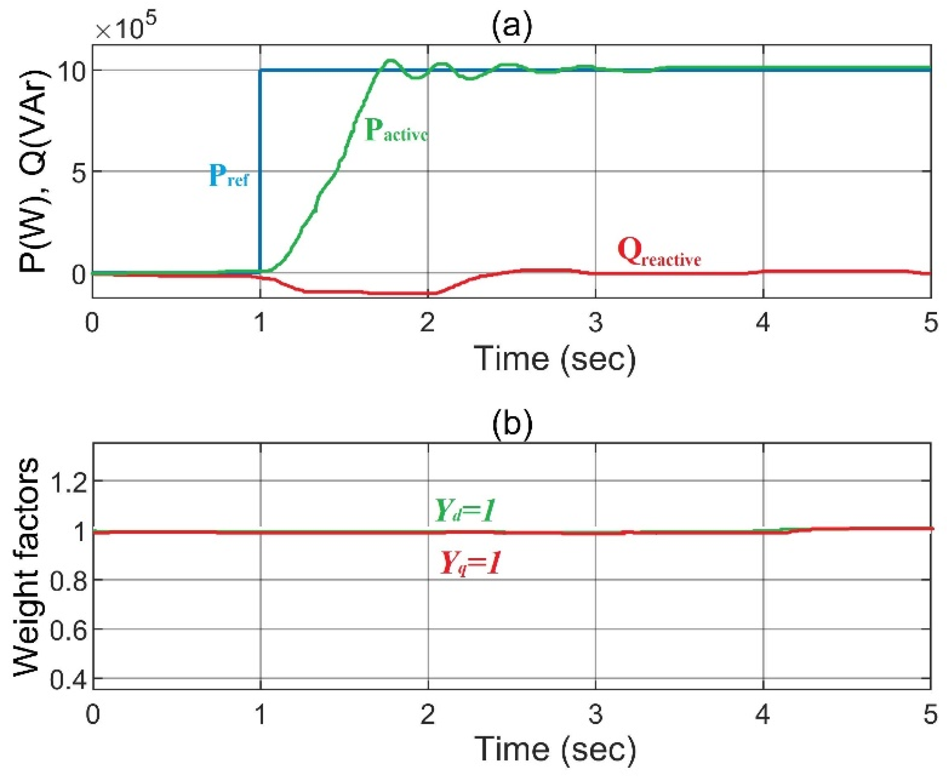
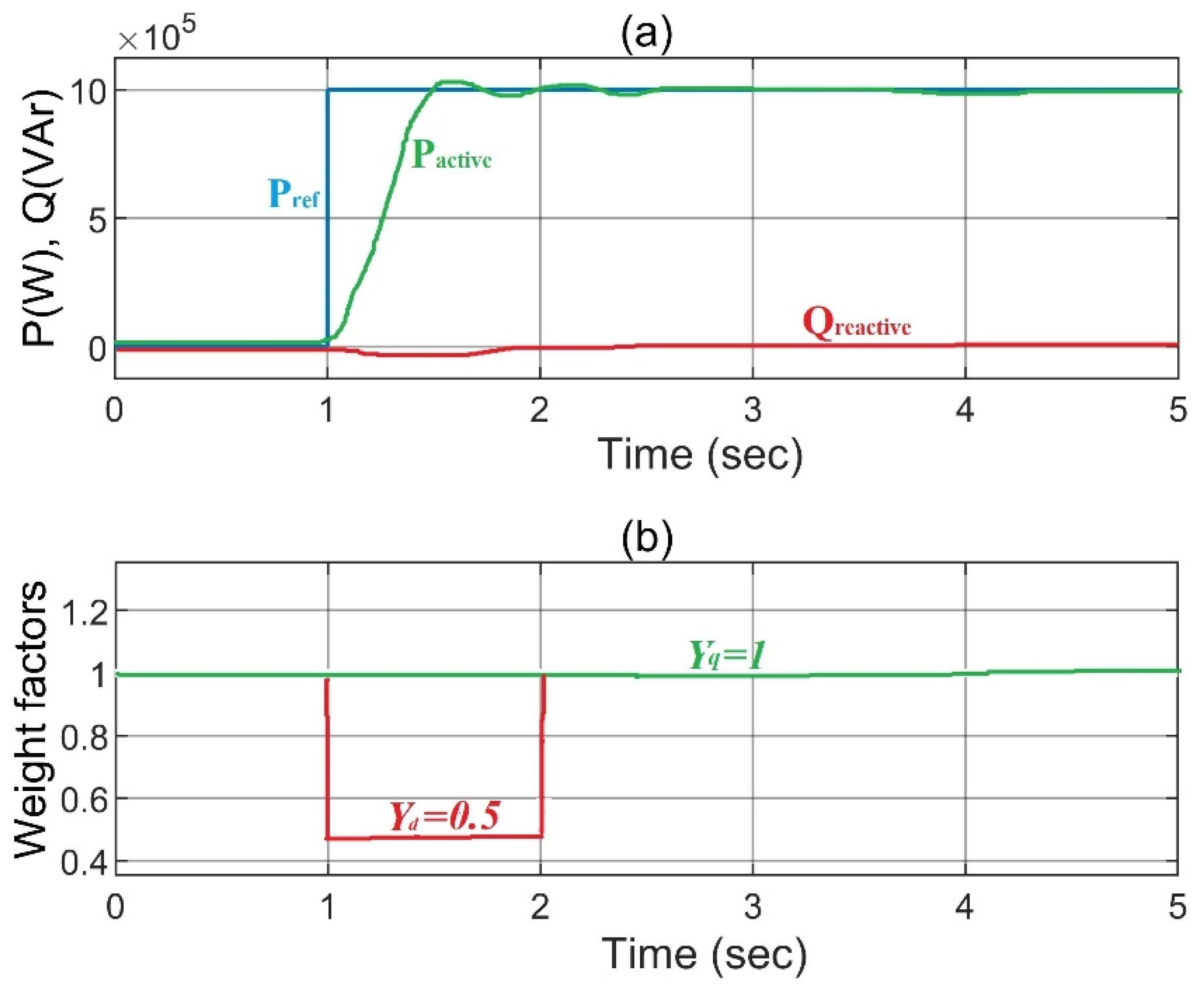
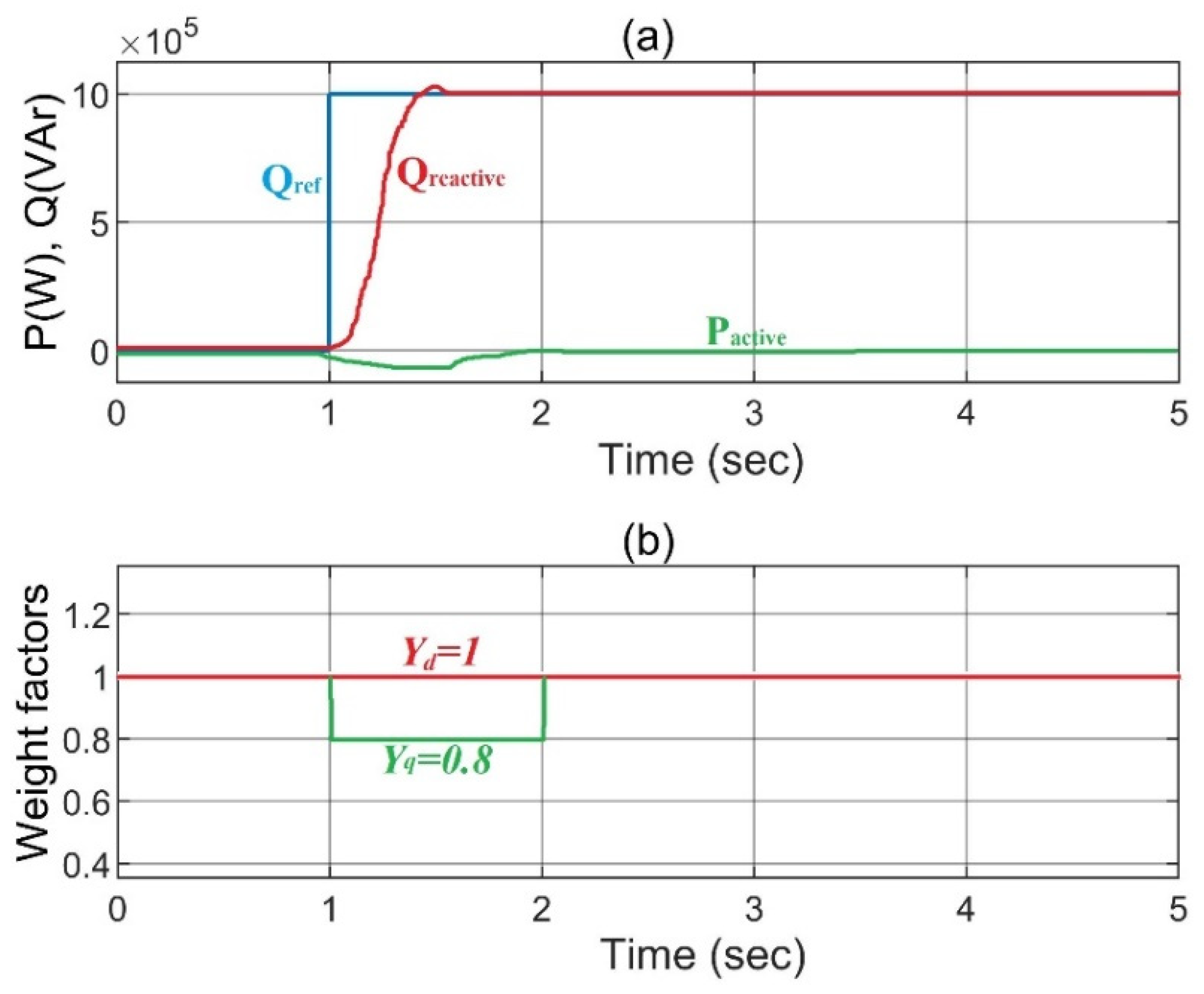
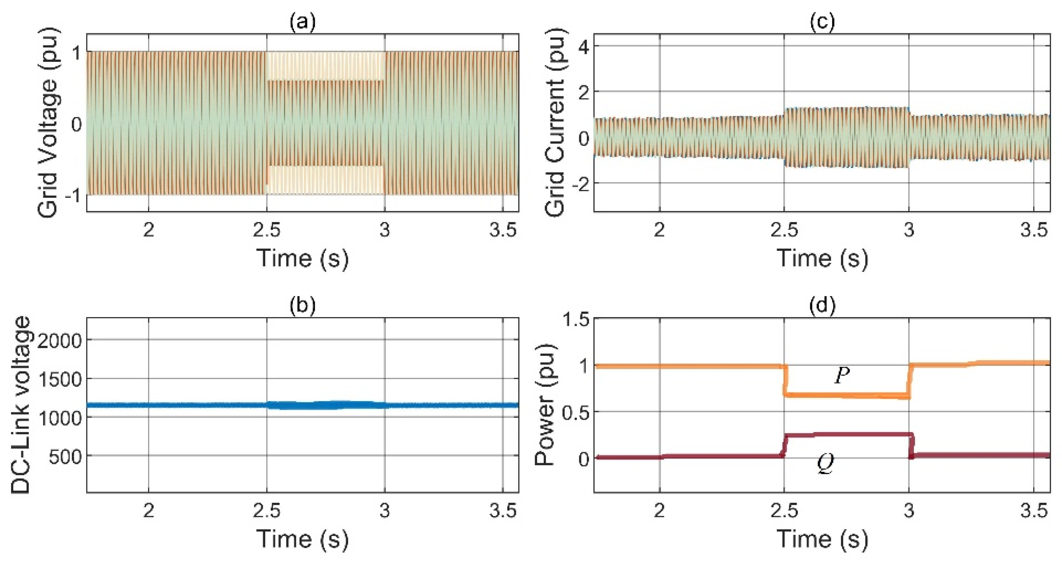
4.1. Analysis of Step-Change in Power (Active/Reactive)
- (a)
- Step-change in Active Power ()
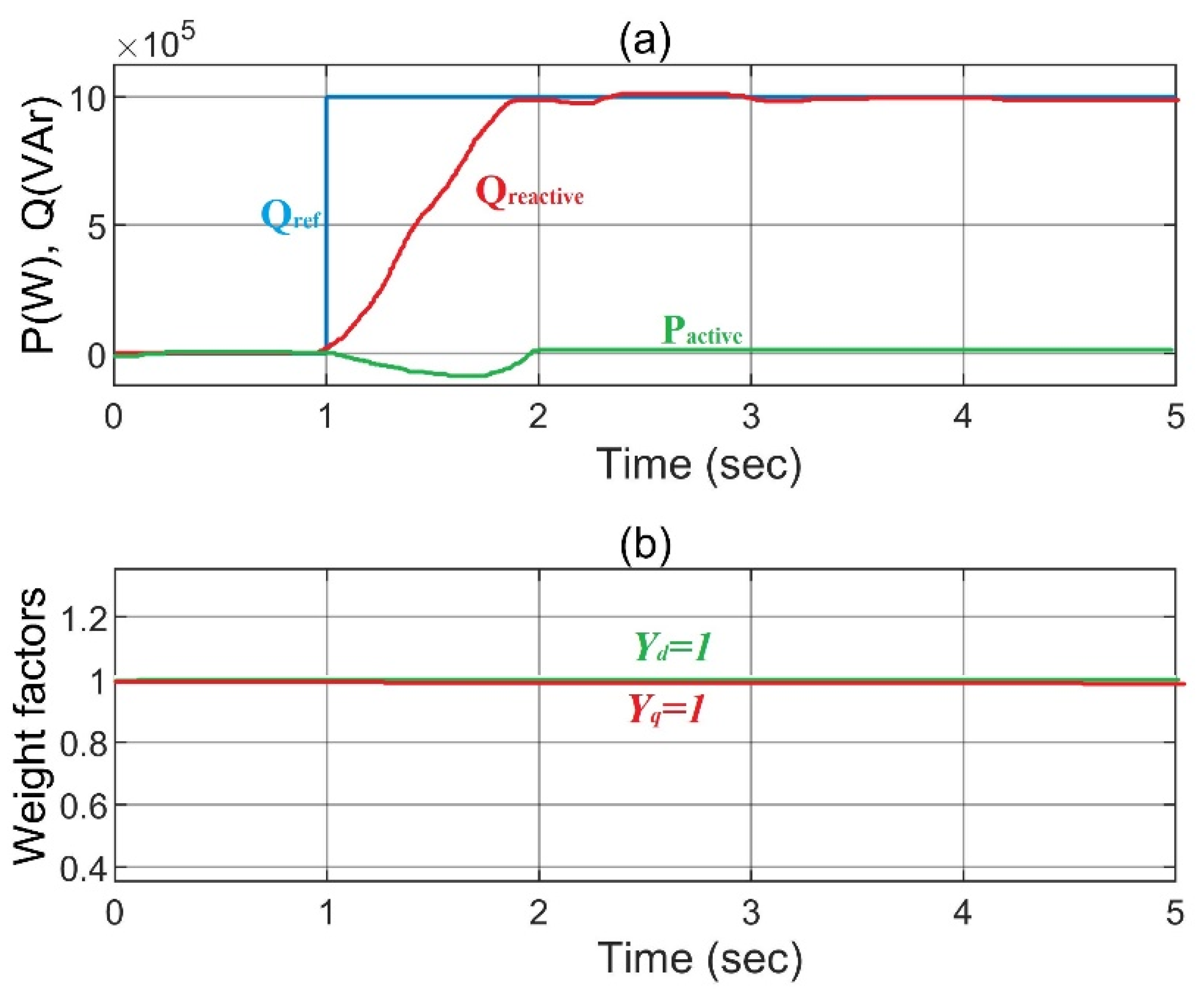
- (b)
- Step-change in Reactive Power ()
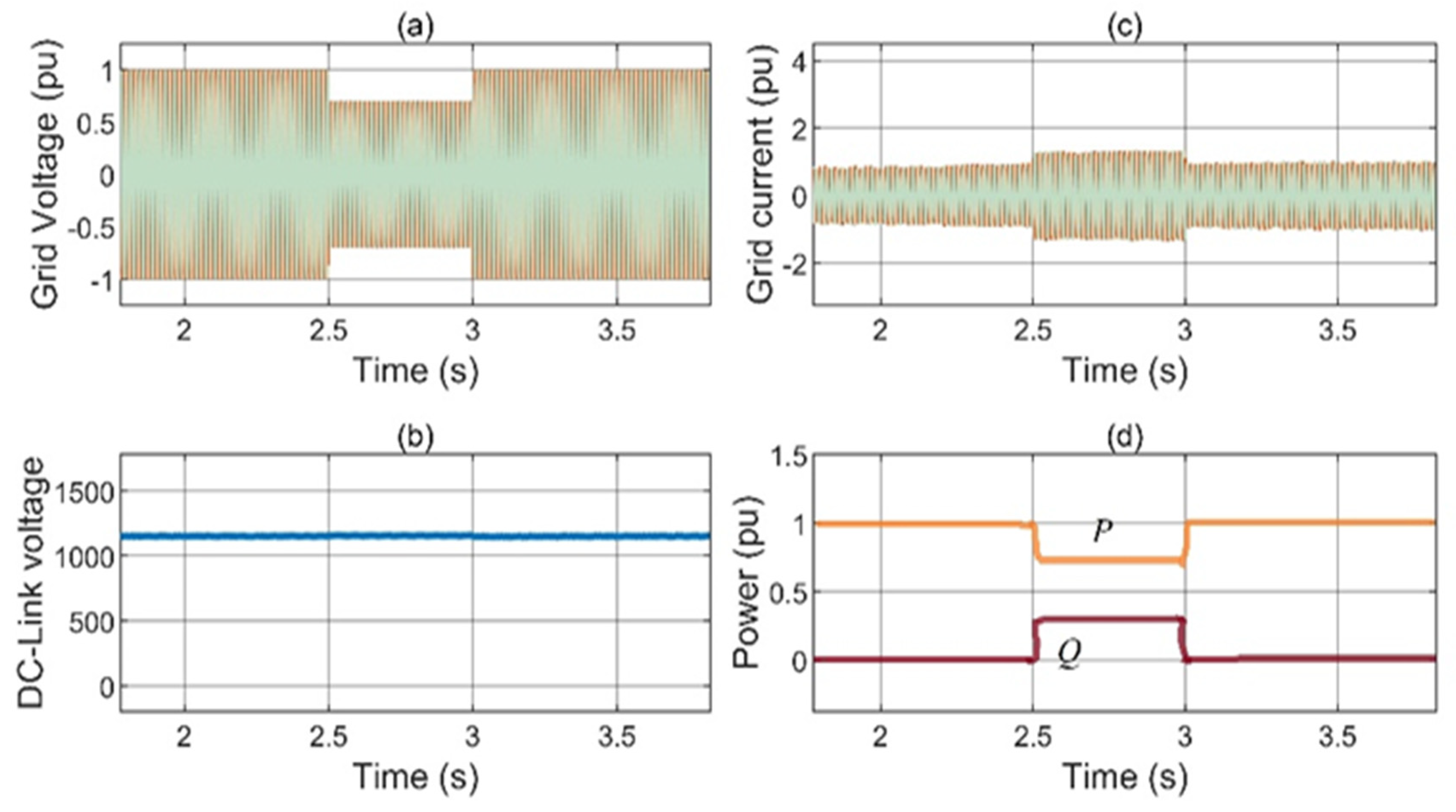
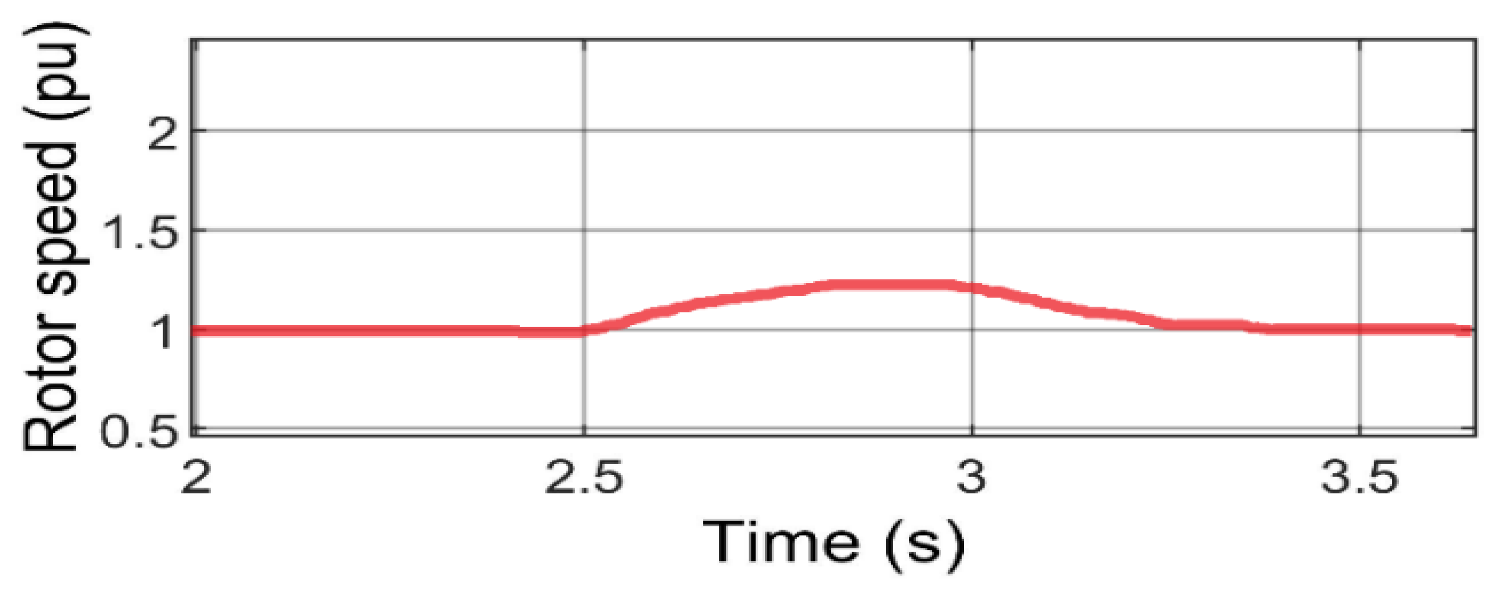
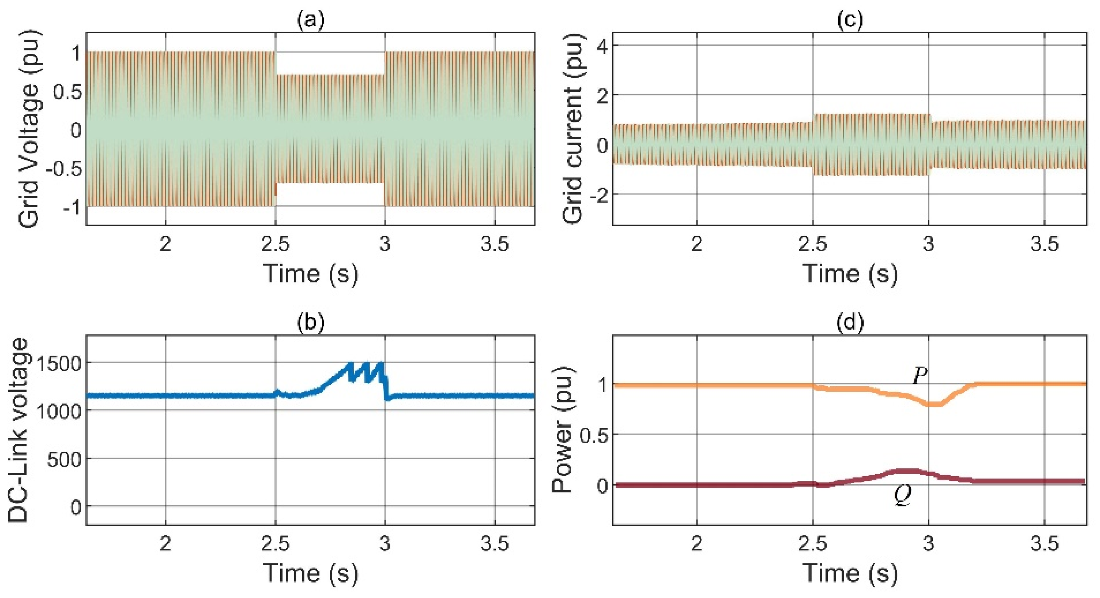
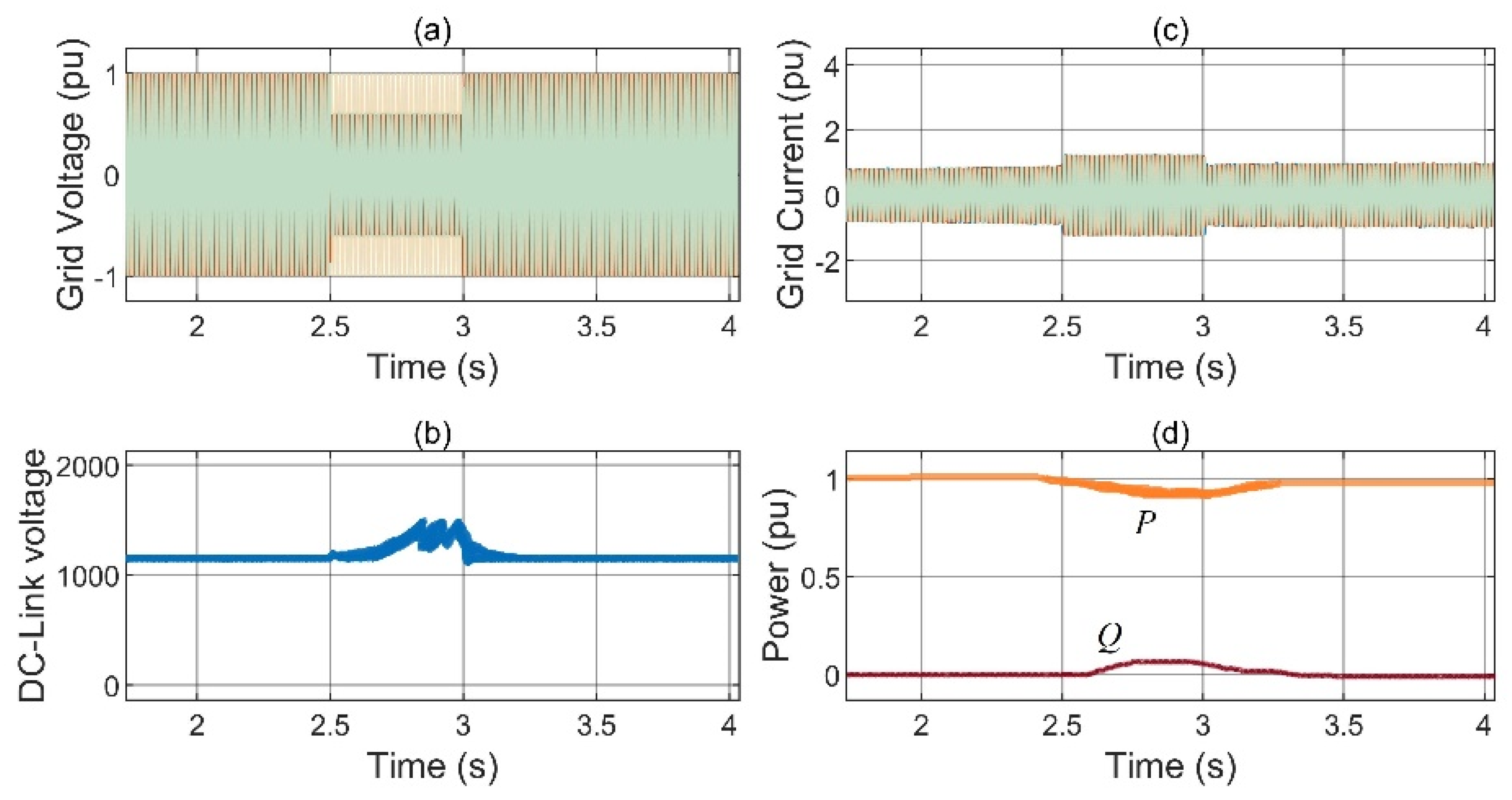
4.2. Fault Analysis on the Grid Side
- (a)
- Symmetrical Fault Analysis
- (b)
- Asymmetrical Fault Analysis
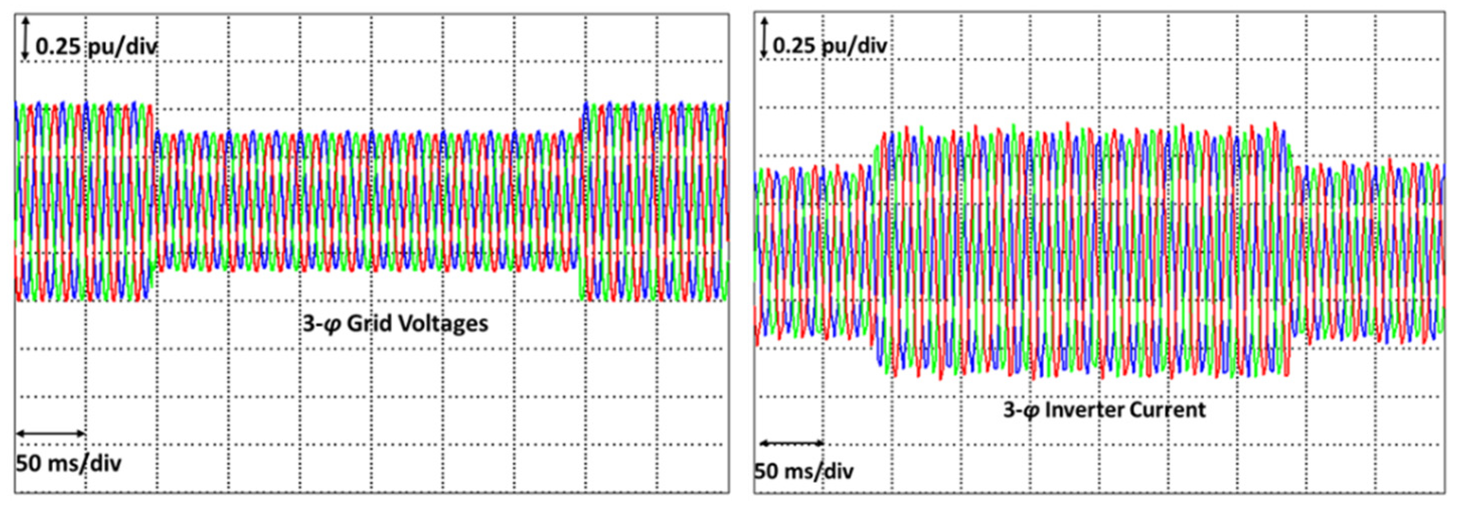
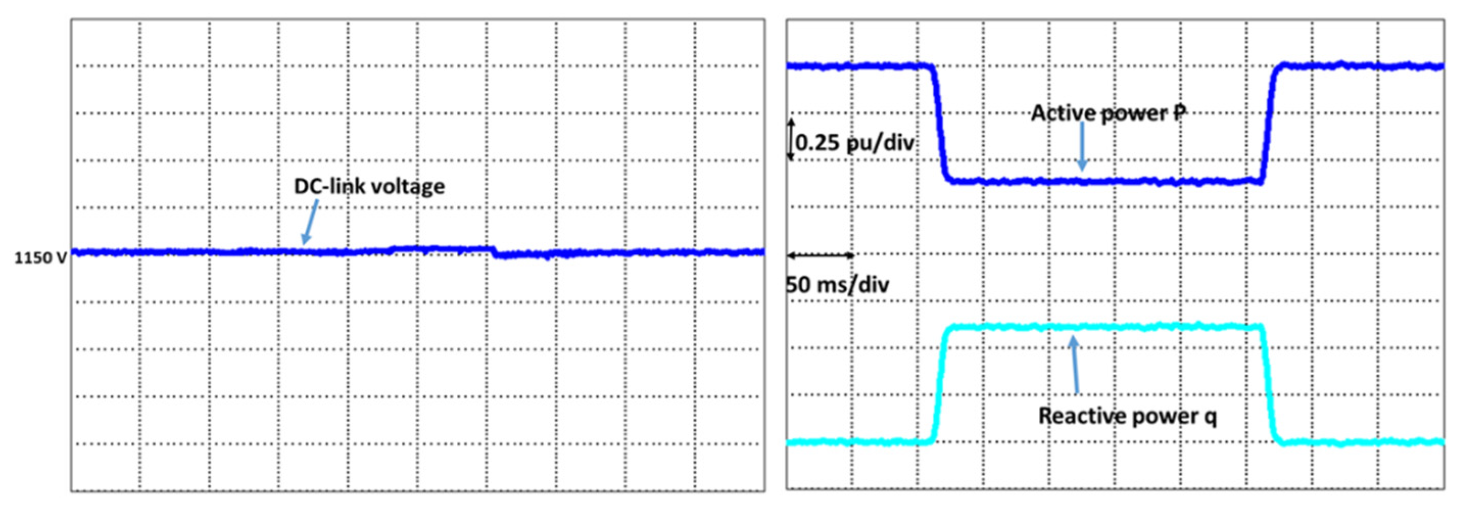
4.3. Experimental Results
4.4. Parameter Robustness Analysis
5. Conclusions
Author Contributions
Funding
Institutional Review Board Statement
Informed Consent Statement
Data Availability Statement
Conflicts of Interest
References
- Noman, F.M.; Alkawsi, G.A.; Abbas, D.; Alkahtani, A.A.; Tiong, S.K.; Ekanayake, J. Comprehensive Review of Wind Energy in Malaysia: Past, Present, and Future Research Trends. IEEE Access 2020, 8, 124526–124543. [Google Scholar] [CrossRef]
- Bajaj, M.; Singh, A.K. Grid Integrated Renewable DG Systems: A Review of Power Quality Challenges and State-of-the-Art Mitigation Techniques. Int. J. Energy Res. 2020, 44, 26–69. [Google Scholar] [CrossRef]
- Ali, S.W.; Sadiq, M.; Terriche, Y.; Naqvi, S.A.R.; Hoang, L.Q.N.; Mutarraf, M.U.; Hassan, M.A.; Yang, G.; Su, C.L.; Guerrero, J.M. Offshore Wind Farm-Grid Integration: A Review on Infrastructure, Challenges, and Grid Solutions. IEEE Access 2021, 9, 102811–102827. [Google Scholar] [CrossRef]
- Xie, Q.; Zheng, Z.; Huang, C.; Dai, T. Coordinated Fault Ride Through Method for PMSG-Based Wind Turbine Using SFCL and Modified Control Strategy. IEEE Trans. Appl. Supercond. 2021, 31, 1–5. [Google Scholar] [CrossRef]
- Mahela, O.P.; Gupta, N.; Khosravy, M.; Patel, N. Comprehensive Overview of Low Voltage Ride through Methods of Grid Integrated Wind Generator. IEEE Access 2019, 7, 99299–99326. [Google Scholar] [CrossRef]
- Shi, K.; Song, W.; Xu, P.; Liu, R.; Fang, Z.; Ji, Y. Low-Voltage Ride-Through Control Strategy for a Virtual Synchronous Generator Based on Smooth Switching. IEEE Access 2017, 6, 2703–2711. [Google Scholar] [CrossRef]
- E.ON2006-Netz-Grid Code-High and Extra High Voltage. Available online: https://wenku.baidu.com/view/6289c22bcfc789eb172dc88e.html (accessed on 6 October 2022).
- Cardenas, R.; Pena, R.; Alepuz, S.; Asher, G. Overview of Control Systems for the Operation of DFIGs in Wind Energy Applications. IEEE Trans. Ind. Electron. 2013, 60, 2776–2798. [Google Scholar] [CrossRef]
- Yujun, L.; Yuan, X.; Li, J.; Xu, Z. Novel Grid-Forming Control of Permanent Magnet Synchronous Generator-Based Wind Turbine for Integrating Weak AC Grid without Sacrificing Maximum Power Point Tracking Demand as Frequency Controlled Reserve View Project Stability Analysis and Control Scheme. IET Gener. Transm. Distrib. 2021, 15, 1613–1625. [Google Scholar] [CrossRef]
- Benbouhenni, H.; Bizon, N. Advanced Direct Vector Control Method for Optimizing the Operation of a Double-Powered Induction Generator-Based Dual-Rotor Wind Turbine System. Mathematics 2021, 9, 2403. [Google Scholar] [CrossRef]
- Qais, M.H.; Hasanien, H.M.; Alghuwainem, S. Optimal Transient Search Algorithm-Based PI Controllers for Enhancing Low Voltage Ride-Through Ability of Grid-Linked PMSG-Based Wind Turbine. Electronics 2020, 9, 1807. [Google Scholar] [CrossRef]
- Yuan, L.; Meng, K.; Huang, J.; Dong, Z.Y. Investigating Subsynchronous Oscillations Caused by Interactions between PMSG-Based Wind Farms and Weak AC Systems. Int. J. Electr. Power Energy Syst. 2020, 115, 105477. [Google Scholar] [CrossRef]
- Pan, L.; Wang, X. Variable Pitch Control on Direct-Driven PMSG for Offshore Wind Turbine Using Repetitive-TS Fuzzy PID Control. Renew. Energy 2020, 159, 221–237. [Google Scholar] [CrossRef]
- Kapetanaki, A.; Levi, V.; Buhari, M.; Schachter, J.A. Maximization of Wind Energy Utilization Through Corrective Scheduling and FACTS Deployment. IEEE Trans. Power Syst. 2017, 32, 4764–4773. [Google Scholar] [CrossRef] [Green Version]
- Manohar, G.; Venkateshwarlu, S.; JayaLaxmi, A. An Elite Approach for Enhancement of LVRT in Doubly Fed Induction Generator (DFIG)-Based Wind Energy Conversion System (WECS): A FAMSANFIS Approach. Soft Comput. 2022, 26, 11315–11337. [Google Scholar] [CrossRef]
- Li, P.; Xiong, L.; Wu, F.; Ma, M.; Wang, J. Sliding Mode Controller Based on Feedback Linearization for Damping of Sub-Synchronous Control Interaction in DFIG-Based Wind Power Plants. Int. J. Electr. Power Energy Syst. 2019, 107, 239–250. [Google Scholar] [CrossRef]
- Muftau, B.; Fazeli, M.; Egwebe, A. Stability Analysis of a PMSG Based Virtual Synchronous Machine. Electr. Power Syst. Res. 2020, 180, 106170. [Google Scholar] [CrossRef]
- Haidar, A.M.A.; Muttaqi, K.M.; Hagh, M.T. A Coordinated Control Approach for DC Link and Rotor Crowbars to Improve Fault Ride-through of Dfig-Based Wind Turbine. IEEE Trans. Ind. Appl. 2017, 53, 4073–4086. [Google Scholar] [CrossRef]
- Gebru, F.M.; Khan, B.; Alhelou, H.H. Analyzing Low Voltage Ride through Capability of Doubly Fed Induction Generator Based Wind Turbine. Comput. Electr. Eng. 2020, 86, 106727. [Google Scholar] [CrossRef]
- Yan, L.; Chen, X.; Zhou, X.; Sun, H.; Jiang, L. Perturbation Compensation-Based Non-Linear Adaptive Control of ESS-DVR for the LVRT Capability Improvement of Wind Farms. IET Renew. Power Gener. 2018, 12, 1500–1507. [Google Scholar] [CrossRef] [Green Version]
- Chawda, G.S.; Shaik, A.G.; Mahela, O.P.; Padmanaban, S.; Holm-Nielsen, J.B. Comprehensive Review of Distributed FACTS Control Algorithms for Power Quality Enhancement in Utility Grid with Renewable Energy Penetration. IEEE Access 2020, 8, 107614–107634. [Google Scholar] [CrossRef]
- Sayahi, K.; Kadri, A.; Bacha, F.; Marzougui, H. Implementation of a D-STATCOM Control Strategy Based on Direct Power Control Method for Grid Connected Wind Turbine. Int. J. Electr. Power Energy Syst. 2020, 121, 106105. [Google Scholar] [CrossRef]
- Nasiri, M.; Mohammadi, R. Peak Current Limitation for Grid Side Inverter by Limited Active Power in PMSG-Based Wind Turbines During Different Grid Faults. IEEE Trans. Sustain. Energy 2017, 8, 3–12. [Google Scholar] [CrossRef]
- Yaramasu, V.; Wu, B. Model Predictive Control of Wind Energy Conversion Systems; Wiley: New York, NY, USA, 2017; ISBN 9781118988589. [Google Scholar]
- Sadiq, M.; Aragon, C.A.; Terriche, Y.; Ali, S.W.; Su, C.-L.; Buzna, Ľ.; Elsisi, M.; Lee, C.-H. Continuous-Control-Set Model Predictive Control for Three-Level DC–DC Converter with Unbalanced Loads in Bipolar Electric Vehicle Charging Stations. Mathematics 2022, 10, 3444. [Google Scholar] [CrossRef]
- Azab, M. A Finite Control Set Model Predictive Control Scheme for Single-Phase Grid-Connected Inverters. Renew. Sustain. Energy Rev. 2021, 135, 110131. [Google Scholar] [CrossRef]
- Babaghorbani, B.; Beheshti, M.T.; Talebi, H.A. A Lyapunov-Based Model Predictive Control Strategy in a Permanent Magnet Synchronous Generator Wind Turbine. Int. J. Electr. Power Energy Syst. 2021, 130, 106972. [Google Scholar] [CrossRef]
- Kou, P.; Liang, D.; Li, J.; Gao, L.; Ze, Q. Finite-Control-Set Model Predictive Control for DFIG Wind Turbines. IEEE Trans. Autom. Sci. Eng. 2018, 15, 1004–1013. [Google Scholar] [CrossRef]
- Caseiro, L.M.A.; Mendes, A.M.S.; Cruz, S.M.A. Dynamically Weighted Optimal Switching Vector Model Predictive Control of Power Converters. IEEE Trans. Ind. Electron. 2019, 66, 1235–1245. [Google Scholar] [CrossRef]
- Li, X.; Zhang, H.; Shadmand, M.B.; Balog, R.S. Model Predictive Control of a Voltage-Source Inverter with Seamless Transition between Islanded and Grid-Connected Operations. IEEE Trans. Ind. Electron. 2017, 64, 7906–7918. [Google Scholar] [CrossRef]
- Thapa, K.B.; Jayasawal, K. Pitch Control Scheme for Rapid Active Power Control of a PMSG-Based Wind Power Plant. IEEE Trans. Ind. Appl. 2020, 56, 6756–6766. [Google Scholar] [CrossRef]
- Rahimi, M. Mathematical Modeling, Dynamic Response Analysis, and Control of PMSG-Based Wind Turbines Operating with an Alternative Control Structure in Power Control Mode. Int. Trans. Electr. Energy Syst. 2017, 27, e2423. [Google Scholar] [CrossRef]
- Prior, G.; Krstic, M. A Control Lyapunov Approach to Finite Control Set Model Predictive Control for Permanent Magnet Synchronous Motors. J. Dyn. Syst. Meas. Control. Trans. ASME 2015, 137, 011001. [Google Scholar] [CrossRef] [Green Version]
- Xia, C.; Liu, T.; Shi, T.; Song, Z. A Simplified Finite-Control-Set Model-Predictive Control for Power Converters. IEEE Trans. Ind. Inform. 2014, 10, 991–1002. [Google Scholar] [CrossRef]
- Grid Converters for Photovoltaic and Wind Power Systems|IEEE EBooks|IEEE Xplore. Available online: https://ieeexplore.ieee.org/book/5732788 (accessed on 19 December 2021).
- Alepuz, S.; Calle, A.; Busquets-Monge, S.; Kouro, S.; Wu, B. Use of Stored Energy in PMSG Rotor Inertia for Low-Voltage Ride-through in Back-to-Back NPC Converter-Based Wind Power Systems. IEEE Trans. Ind. Electron. 2013, 60, 1787–1796. [Google Scholar] [CrossRef]
- Amer Saeed, M.; Mehroz Khan, H.; Ashraf, A.; Aftab Qureshi, S. Analyzing Effectiveness of LVRT Techniques for DFIG Wind Turbine System and Implementation of Hybrid Combination with Control Schemes. Renew. Sustain. Energy Rev. 2018, 81, 2487–2501. [Google Scholar] [CrossRef]
- Talha, M.; Raihan, S.R.S.; Rahim, N.A. PV Inverter with Decoupled Active and Reactive Power Control to Mitigate Grid Faults. Renew. Energy 2020, 162, 877–892. [Google Scholar] [CrossRef]
- Dai, J.; Xu, D.; Wu, B.; Zargari, N.R. Unified DC-Link Current Control for Low-Voltage Ride-through in Current-Source-Converter-Based Wind Energy Conversion Systems. IEEE Trans. Power Electron. 2010, 26, 288–297. [Google Scholar]
- Barros, L.S.; Barros, C.M.V. An Internal Model Control for Enhanced Grid-Connection of Direct-Driven PMSG-Based Wind Generators. Electr. Power Syst. Res. 2017, 151, 440–450. [Google Scholar] [CrossRef]


| State | Sa | Sb | Sc | Vector |
|---|---|---|---|---|
| 0 | 0 | 0 | 0 | 0 |
| 1 | 1 | 0 | 0 | VDC |
| 2 | 1 | 1 | 0 | VDC |
| 3 | 0 | 1 | 0 | VDC |
| 4 | 0 | 1 | 1 | VDC |
| 5 | 0 | 1 | 1 | VDC |
| 6 | 1 | 0 | 1 | VDC |
| 7 | 1 | 1 | 1 | 0 |
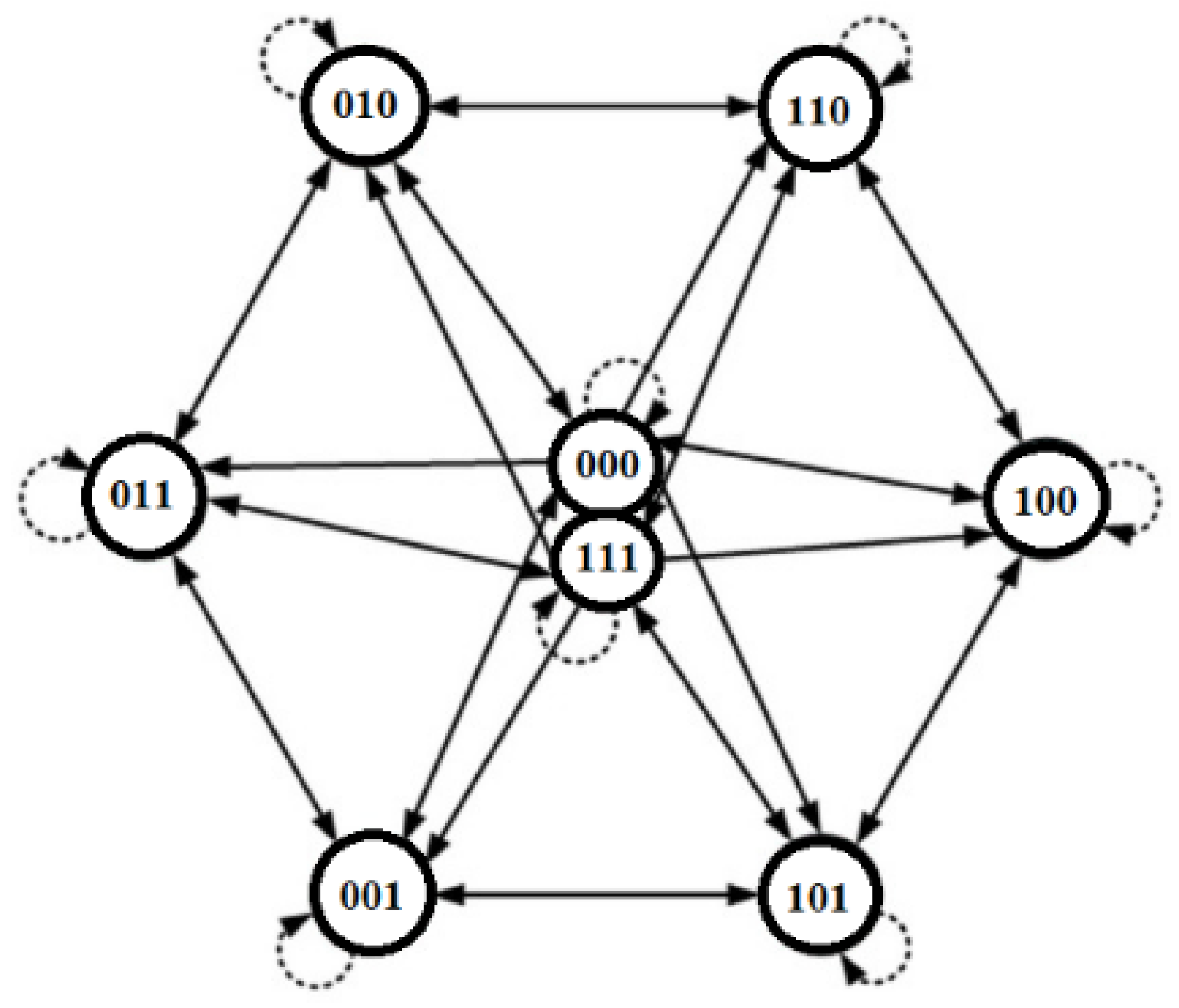
| States | Existing States | Subsequent States |
|---|---|---|
| 0 | (000) | (000) (001) (100) (010) |
| 1 | (100) | (000) (100) (101) (110) |
| 2 | (110) | (100) (010) (110) (111) |
| 3 | (010) | (000) (010) (011) (110) |
| 4 | (011) | (001) (010) (011) (111) |
| 5 | (001) | (000) (001) (011) (101) |
| 6 | (101) | (001) (100) (101) (111) |
| 7 | (111) | (101) (011) (110) (111) |
| Parameter | Abrupt Active Power Change Sp < Sq | Steady-State Sp = Sq | Abrupt Reactive Power Change Sp > Sq |
|---|---|---|---|
| (0.4–1) | 1 | 1 | |
| 1 | 1 | (0.2–0.8) |
| Parameter | Value |
|---|---|
| Rated Power | 1.50 MW |
| Grid Voltage | 576 V |
| DC link voltage | 1150 V |
| Stator Resistor | 3.2 mΩ |
| Stator Resistor | 3.05 mH |
| Switching Frequency | 20 KHz |
| DC-Link Capacitor | 0.025 F |
| Filter Resistor | 3.154 mΩ |
| Filter Inductor | 0.44 mH |
| Features | PI Controller | FCS MPC |
|---|---|---|
| Parameter Decoupling | External | Internal |
| Tuning | Retuning required | Easy, no retuning needed |
| Secondary axis current control | Additional PI regulators required | Single cost function for error mitigation |
| Dynamic response | Slow | Fast |
| Computation burden | Medium | High |
Publisher’s Note: MDPI stays neutral with regard to jurisdictional claims in published maps and institutional affiliations. |
© 2022 by the authors. Licensee MDPI, Basel, Switzerland. This article is an open access article distributed under the terms and conditions of the Creative Commons Attribution (CC BY) license (https://creativecommons.org/licenses/by/4.0/).
Share and Cite
Ali, S.W.; Verma, A.K.; Terriche, Y.; Sadiq, M.; Su, C.-L.; Lee, C.-H.; Elsisi, M. Finite-Control-Set Model Predictive Control for Low-Voltage-Ride-Through Enhancement of PMSG Based Wind Energy Grid Connection Systems. Mathematics 2022, 10, 4266. https://doi.org/10.3390/math10224266
Ali SW, Verma AK, Terriche Y, Sadiq M, Su C-L, Lee C-H, Elsisi M. Finite-Control-Set Model Predictive Control for Low-Voltage-Ride-Through Enhancement of PMSG Based Wind Energy Grid Connection Systems. Mathematics. 2022; 10(22):4266. https://doi.org/10.3390/math10224266
Chicago/Turabian StyleAli, Syed Wajahat, Anant Kumar Verma, Yacine Terriche, Muhammad Sadiq, Chun-Lien Su, Chung-Hong Lee, and Mahmoud Elsisi. 2022. "Finite-Control-Set Model Predictive Control for Low-Voltage-Ride-Through Enhancement of PMSG Based Wind Energy Grid Connection Systems" Mathematics 10, no. 22: 4266. https://doi.org/10.3390/math10224266