Article

MHD Mixed Convection of Hybrid Ferrofluid Flow over an Exponentially Stretching/Shrinking Surface with Heat Source/Sink and Velocity Slip

1
Department of Mathematics, Universiti Pertahanan Nasional Malaysia, Kuala Lumpur 57000, Malaysia
2
Department of Mathematical Sciences, Faculty of Science and Technology, Universiti Kebangsaan Malaysia, Bangi 43600, Selangor, Malaysia
3
Department of Mathematics, Babeş-Bolyai University, R-400084 Cluj-Napoca, Romania
*
Author to whom correspondence should be addressed.
Mathematics 2022, 10(23), 4400; https://doi.org/10.3390/math10234400
Submission received: 20 September 2022 / Revised: 11 November 2022 / Accepted: 17 November 2022 / Published: 22 November 2022

Abstract

:
This paper investigates the mixed convection flow related to Fe 3 O 4 - CoFe 2 O 4 / water hybrid ferrofluids on stagnation point over an exponentially stretching/shrinking surface with the influence of magnetohydrodynamic (MHD), velocity slip, and heat source/sink. The proposed system of differential equations is reduced using the similarity transformation procedure that is numerically solvable using MATLAB. Dual solutions are obtained for various governing parameters, in which the first solution is found to be in a stable state via the stability analysis. The CoFe2O4 nanoparticles volume fraction increases the heat transfer rate and the skin friction coefficient while delaying the separation of the boundary layer at the bifurcation point. Adding CoFe2O4 nanoparticles in hybrid ferrofluids gives a better heat transfer rate than that obtained with ferrofluids. The presence of a magnetic field enhances the fluid flow velocity. The increased strengths of the heat sink and stretching parameters give better results on the heat transfer, while the results are reversed for the heat source and shrinking parameters. The presence of velocity slip does influence the skin friction and the fluid flow.

1. Introduction

Due to its industrial significance, nanotechnology has become more prevalent in various industries. Nanotechnology involves the use of nanoparticles and a base fluid to transfer heat, which has become a new category of heat transfer fluids. Choi and Eastman [1] introduced the term nanofluids as a way to introduce an entirely new type of fluid. Saidur et al. [2] also demonstrated that nanofluids have greater thermophysical properties and heat transfer efficiency than traditional fluids (water, glycerol). Moreover, Sidik et al. [3] and Sidik et al. [4] reviewed the application of nanofluids. For those reasons, numerous investigations have been accomplished to study boundary layer flow and heat transfer in nanofluids [5,6,7,8]. In contrast, magnetic nanofluid or ferrofluid is a suspension of magnetic nanoparticles held together by a colloidal relationship (magnetite, hematite, or cobalt ferrite) in a non-magnetic base fluid (ethylene glycol, oil, or water) [9]. In heat transfer problems, research into ferrofluids has received much attention because of the multitude of applications for ferrofluids in nanotechnology industries, such as heat exchangers, coolants in thermal management devices, and operations related to the transfer of heat, including boiling and improvised cooling functions of loudspeakers [10,11]. More significantly, the use of ferrofluids in biomedical fields has been highlighted since they make it easier to diagnose and treat diseases including rheumatoid arthritis, cancer, and angiocardiopathy [12]. Ferrofluid research is, therefore, thought to have a bright future and hold the potential to further transdisciplinary studies in biology, chemistry, physics, and material science. Due to this reason, several academicians and researchers have conducted experimental investigations on the behavior of ferrofluids toward heat transfer problems [13,14,15,16,17].
Recently, as a new ferrofluid category, hybrid ferrofluids have been investigated in numerous studies by researchers to assess their relationships with heat transfer and thermal efficiency. Hybrid ferrofluids are substances composed of two or more magnetic nanoparticles in a base fluid. Hybrid ferrofluids have been studied in numerous heat exchange processes and are used for a wide range of purposes. Many researchers are interested in using hybrid ferrofluids to address real-world heat transfer problems, with some of these noteworthy applications including damping, dynamic sealing, heat dissipation, etc. These applications have attracted the attention of many researchers regarding the use of hybrid ferrofluids. However, an examination of the published literature indicates that there are still very few papers about hybrid ferrofluids’ flow and heat transfer. The liquid film flow and heat transfer in a magnetohydrodynamic (MHD) hybrid ferrofluid in the presence of radiation and an irregular heat source/sink were studied by Kumar et al. [18]. They noticed that compared to ferrofluid, a hybrid ferrofluid delivers a better rate of heat transmission. Following these, a continued study by Tlili et al. [19] was conducted on an MHD hybrid ferrofluid with the influence of asymmetrical heat rise/fall. Furthermore, Manh et al. [20] examined the radiation effect in the heat transfer of an MHD hybrid ferrofluid immersed in porous media. An experimental procedure with aqueous hybrid ferrofluid was performed by Giwa et al. [21]. The authors considered the effect of uniform magnetic induction in a rectangular cavity and obtained positive results for the heat performance of hybrid ferrofluid compared to mono-nanoparticle. Recent work by Anuar et al. [22] studied the stagnation flow of a hybrid ferrofluid past an exponentially stretching/shrinking sheet under the influence of external heat and a magnetic field. They discovered from their research that an increase in the volume percentage of CoFe 2 O 4 nanoparticles tended to postpone the boundary layer separation.
Studies regarding the flow characteristics and heat transfer of mixed convection have been carried out due to the great practical interest. Mixed convection is a combination of natural (free) and forced convection. It occurs when free and forced convection mechanisms are at work at a given time to contribute to flow and heat transfer. For example, Sparrow et al. [23] applied the aiding and opposing flow in mixed convection to study boundary layer flow. Afterwards, researchers’ interest in mixed convection rose, providing some notable mention [24,25,26,27]. Since then, with the hope of greatly enhancing aspects of boundary layer and heat transfer, researchers have already begun considering MHD in mixed convective flow. Moreover, the MHD term is essential in checking the heat transfer in creating value products (MHD generator, nuclear reactor, MHD power generation), as it relies upon the heat observing variable [28]. By accounting for the effect of the magnetic field in the mixed convection flow, Khan and Rasheed [29] looked into the heat transfer performance of nanofluid in MHD mixed convection flow with thermal radiation. They discovered that the presence of MHD reduced the skin friction and slowed the fluid flow velocity due to the resistance from the Lorentz force in flow. Furthermore, Wahid et al. [30] conducted a study on the effects of thermal radiation on mixed convection flow of hybrid nanofluid in the presence of MHD. They noticed from their study that as thermal radiation and magnetic values rose, the heat transfer performance was enhanced. Over the years, the study of boundary layer and heat transfer in MHD mixed convection flow has been an interesting subject explored among researchers and provides some quality mentions [31,32,33,34].
The reliability of the heat control factor-like heat source/sink is important to ensure end-product quality in the manufacturing industry, such as for nuclear reactors, rocket thrust systems, electronic chips, semi-conductor wafers, and many more. For example, Sharma et al. [35] explored the impact of heat source/sink on stagnation-point flow with the surface’s condition in vertical stretching. Then, Jamaludin et al. [36] further investigated the influence of heat source/sink over a permeable stretching/shrinking surface with thermal radiation and magnetic field. Meanwhile, Jamaludin et al. [37] also addressed the issue of mixed convection stagnation-point flow for hybrid nanofluid, Cu Al 2 O 3 / water in the presence of a heat source/sink and magnetic field over a permeable stretching/shrinking surface. Recently, Armaghani et al. [38] applied the L-shape cavity for testing the influence of a heat source/sink under the condition of mixed convection flow in hybrid nanofluid Al 2 O 3 Cu / water , while Zainal et al. [39] considered the unsteady state of rear stagnation-point flow in a hybrid nanofluid with the influence of heat source/sink and magnetic field. Notably, there are some interesting articles that consider the heat source/sink conditions [40,41,42].
In the manufacturing industry (hot rolling, extrusion, and wire drawing), heat transfer over a moving surface to a quiescent ambient medium has already drawn much interest from most manufacturing sectors, since the temperature is higher and energy transfer tends to occur at the moving surface compared to ambient medium [43]. For example, Sakiadis [44] was the first to study the condition of moving surfaces on a boundary layer by considering a uniform speed over a continuous surface and solving it using an integral approach. A continuing study on [44] was conducted by Crane [45] using a two-dimensional boundary layer form on a linear stretching sheet. The first study of heat and mass transfer across an exponentially stretching surface with exponential velocity was performed by Magyari and Keller [46]. Then, the work of [46] was extended by Elbashbeshy [47] with the presence of a suction effect. For a new class of nanofluids, hybrid nanofluids, Anuar et al. [48] explored the existence of a dual solution to stagnation-point flow over a sheet that was exponentially stretching/shrinking with the condition of suction/injection. Of note, there are some interesting articles that consider the moving surface in conditions of exponential stretching/shrinking [49,50,51,52].
The appearance of slip has already been recognized as important over the past decades in the manufacturing industry, since the condition of no-slip boundary in fluid mechanics is not always applicable for several cases in complex fluids. Undoubtedly, the slip effect tends to appear in the system, as mentioned by Hatzikiriakos [53]. Complex fluids such as emulsions, suspensions, foams, and polymer solutions tend to form a wall slip, which exhibits a boundary slip at the wall. This phenomenon has importance in technological applications, for instance, the polishing of artificial heart valves and internal cavities [54,55]. The first studies on linear slip boundary conditions were conducted by Navier [56] and Maxwell [57]. Then, a critical analysis with a comprehensive discussion and argument between no-slip and slip boundary conditions was performed by Rao and Rajagopal [58] in their report. Later, Anuar et al. [59] investigated the heat transfer of carbon nanotubes with the influence of velocity slip and suction effect on mixed convection flow past an exponentially stretching/shrinking surface. It is worth noting that there are some interesting articles on the influence of velocity slips [60,61,62].
Finding dual or non-unique solutions is crucial for studying boundary layer theoretical models, because these solutions can highlight disrupted physical processes past moving surfaces. Particularly in the regulated arrangement, the interrupted physical process expresses the non-physically realizable condition. The disturbed physical process may also briefly appear in practical uses. In order to maintain the productivity of the particular production process, it is crucial to locate dual solutions. In order to make it easier to acquire the dual solutions, the boundary layer model must be solved numerically using the best approach. Convection fluid flow and heat transfer problems can be solved using a variety of methods, such as the Poisson–Boltzmann (PB) theory [63] and the traditional density functional theory (DFT) method. The shooting method was known to produce multiple numerical solutions in the past. The shooting technique, however, loses effectiveness when it comes to making early predictions. Those first guesses must be accurate and must be relatively near to the desired outcome or else dual solutions cannot be found in any other case. This is undoubtedly a time-consuming affair. As Ha [64] mentioned, when tackling a problem sensitive to the initial conditions, the shooting method’s other limitation becomes clear. The bvp4c function in MATLAB was used to solve the current problem, due to its effectiveness in generating several numerical solutions, and regardless of how complex the mathematical model is constructed, finding the non-uniqueness solution is possible. The adaptable bvp4c approach works well for solving a mathematical model with unknowable parameters. The reduced boundary layer mathematical models are solved using the bvp4c function, which is superior to other built-in numerical methods since it has a continuation code [65] that speeds up processing.
From the author’s knowledge and understanding of the recent literature, no previous research includes the mixed convection towards stagnation-point flow in the boundary layer and heat transfer problem in hybrid ferrofluids past an exponentially stretching/shrinking surface. As inspired by the literature mentioned above, the mathematical models will include the mixed convection towards stagnation-point flow in an Fe 3 O 4 - CoFe 2 O 4 / water hybrid ferrofluid for this present work. Other effects, for instance, heat source/sink, magnetic field, and velocity slip past an exponentially stretching/shrinking surface, will be considered in this problem. The mathematical models based on Tiwari and Das’s model [25] will be analyzed. Consequently, the stability analysis will be performed on dual solutions initiated by Merkin [66] and Weidman and Turner [67]. The method of obtaining stability between dual solutions plays a crucial role. It provides a procedure to determine which solution is stable, as already shown by other researchers [22,37,50] in their excellent papers on stability analysis.

2. Mathematical Formulation

A steady, incompressible, and two-dimensional magnetohydrodynamic (MHD) mixed convection flow towards stagnation point over a surface that is stretching/shrinking exponentially in a water-based hybrid ferrofluid ( Fe 3 O 4 - CoFe 2 O 4 / water ) is considered in this present work, as displayed in Figure 1. The x - and y -axes in this case are the Cartesian axes with the origin O, where x is appointed vertically along the surface, and y is perpendicular to it. The impact of the heat source/sink and velocity slip is taken into account for the boundary layer and heat transfer analyses. The wall surface is stretched ( b > 0 ) or shrunk ( b < 0 ) with surface velocity u w ( x ) = b e x / L in the exponential form. B ( x ) is a transverse magnetic field that is perpendicular to the stretching/shrinking surface. Here, T w ( x ) is the surface temperature with T w ( x ) =   T +   T 0 e 2 x / L , whereby T 0 < 0 is the constant cooled surface (opposing flow) and T 0 > 0 is the constant heated surface (assisting flow). When the buoyancy forces resulting from the temperature differential between the wall and the free stream increase and considerably alter the flow and thermal fields, the mixed convection in stagnation flows becomes significant, as reported by Ramachandran et al. [24]. This study also makes the crucial assumption that the stagnation point occurs when T w ( x ) =   T , where the temperature of the plate reaches the same level as the surrounding air. A fluid particle has zero velocity at the stagnation point in the flow field, which is where the fluid region is closest to the stagnation point. The free stream velocity of the flow close to the stagnation point is often given by the equation U = U ( x ) = a e x / L , where a is a constant for a > 0 , x is the distance from stagnation point, and L is denoted as the reference length. The free stream travels in the direction of the plate’s surface before splitting into two to pass it. The velocity at the center of the surface is fully at rest because there is no velocity in either the x or y directions. Here, the center of the surface is referred to as stagnation point.
As for the nanoparticle volume fraction in hybrid ferrofluids ( Fe 3 O 4 - CoFe 2 O 4 / water ), Fe 3 O 4 is the first ferroparticle volume fraction parameter, ϕ 1 , while CoFe 2 O 4 is the second ferroparticle volume fraction parameter, ϕ 2 . The shape formed for the hybrid ferrofluids is in a stable spherical shape of nanoparticle and uniform size, while the agglomeration effects are disregarded. In this instance, Tiwari and Das’ [25] mathematical nanofluid model is used. It is worth noting that this nanofluid model uses a single-phase approach and assumes that all of the particles are homogeneous in size and shape. Additionally, it ignores interactions between the particles and the fluid they are in contact with [68,69]. Since the base fluid can be thought of as acting as a single fluid when it is readily fluidized, this presumption is realistic and supports the use of the single-phase model in this investigation. The boundary layer is assumed to be laminar, as the fluid flow velocity changes evenly as the fluid flow moves away from the wall surface. Of note, the assumption made on the boundary layer approximation is due to the boundary layer’s edge responding to the external flow in the same way that an object’s actual surface would. Therefore, the boundary layer provides every object with an “effective” shape that is typically slightly distinct from its actual shape. Under the assumption of Boussinesq and boundary layer approximations mentioned above, the governing equations can be written as [22,50].
u x + v y = 0 ,
u u x + v u y = U d U d x + μ h n f ρ h n f 2 u y 2 + σ h n f B 2 ρ h n f ( U u ) + ( ρ β ) h n f ρ h n f ( T T ) g ,
u T x + v T y = α h n f 2 T y 2 + Q 1 ( ρ C p ) h n f ( T T ) ,
subject to
u = u w ( x ) + ξ 1 ( x ) u y ,       v = v w ( x ) ,       T = T w ( x )       at     y = 0 , u U ( x ) ,       T T     as       y .
At this point, u represents the velocity component along the x-axis, while v represents the velocity component along the y-axis. The acceleration due to gravity is denoted as g, T represents the hybrid ferrofluid temperature, ξ 1 ( x ) refers to the velocity slip factor, and constant heat source/sink is denoted as Q 1 . Furthermore, ( ρ β ) h n f , ( ρ C p ) h n f μ h n f , ρ h n f and σ h n f portray the thermal expansion coefficient, heat capacitance, dynamic viscosity, density, and electrical conductivity of the hybrid ferrofluids ( Fe 3 O 4 / CoFe 2 O 4 ), respectively. The thermal diffusivity of the hybrid ferrofluids is described as α h n f = k h n f / ( ρ C p ) h n f , where k h n f denotes the thermal conductivity of the hybrid ferrofluids. Here, the theoretical models for thermophysical properties of ferrofluid and hybrid ferrofluids are presented in Table 1, and Table 2 shows the physical properties of nanoparticles Fe 3 O 4 and CoFe 2 O 4 together with H 2 O particles.
For obtaining the similarity solutions of the governing Equations (1)–(3) subject to Equation (4), the terms v w ( x ) , B ( x ) , Q 1 ( x ) and ξ 1 ( x ) are given in the following form [26,50,52]:
v w ( x ) =   a v f 2 L e x / 2 L s ,       B ( x ) = B 0 e x / 2 L ,       Q 1 ( x ) = Q 0 e x / L ,       ξ 1 ( x ) = ξ 0 e x / 2 L ,
where continuous mass flux velocity is denoted as s with suction condition ( s > 0 ) , injection condition ( s < 0 ) , and impenetrable surface ( s = 0 ) , while B 0 , Q 0 and ξ 0 are constants. Next, an appropriate similarity transformation is considered as follows by pursuing [50].
u = a e x / L f ( η ) ,       v = a v f 2 L e x / 2 L   ( f ( η ) + η f ( η ) ) , θ ( η ) = T T   T w T ,       η = a 2 v f L e x / 2 L y ,
where f indicates differentiation concerning η . Here, the reduction of the differential equation will be made by implying Equations (5) and (6) into Equations (2) and (3) along with Equation (4). A reduced form of governing boundary layer system is obtained as follows:
μ h n f μ f f + ρ h n f ρ f ( f f 2 ( f ) 2 + 2 ) + σ h n f σ f M ( 1 f ) + 2 ( ρ β ) h n f ( ρ β ) f λ θ = 0 ,
1 Pr k h n f k f θ + ( ρ C p ) h n f ( ρ C p ) f ( f θ 4 f θ ) + Q θ = 0 ,
subject to
f ( η ) = s ,       f ( η ) = c + ξ f ( η ) ,       θ ( η ) = 1   at   η = 0 f ( η ) = 1 ,       θ ( η ) = 0   as   η .
Here, λ represents the mixed convection parameter with the case opposing flow ( λ < 0 ) and assisting flow ( λ > 0 ) , Pr indicates the Prandtl number, M denotes the magnetic parameter, Q represents the presence of heat source ( Q > 0 ) and heat sink ( Q < 0 ) , c denotes stretching ( c > 0 ) and shrinking ( c < 0 ) parameter on the surface, and ξ is the velocity slip parameter, which is defined as follows:
M = 2 L B 0 2 σ f a ρ f ,       λ = G r x Re x 2 ,       Pr = ( μ C p ) f k f ,   Q = 2 L Q 0 a ( ρ C p ) f ,       c = b a ,       ξ = ξ 0 a 2 v f L ,
where the local Reynolds number Re x and the local Grashof number G r x are given by
G r x = g β f ( T w T ) L 3 v f ,       Re x = L U ( x ) ν f .
Next, the skin friction coefficient C f and the local Nusselt number N u x , as the physical quantities of practical interest in this problem, are defined as follows [50]:
C f = τ w ρ f U 2 ,       N u x = L q w k f ( T w T ) ,
where q w is the surface heat flux and τ w is the wall shear stress, as defined below:
τ w = μ h n f ( u y ) y = 0 ,       q w = k h n f ( T y ) y = 0 .
Using Equation (6) in Equations (12) and (13), the following is obtained:
2   Re x 1 / 2 C f = μ h n f μ f f ( 0 ) ,       2   Re x 1 / 2 N u x = k h n f k f θ ( 0 ) .

3. Stability Analysis

There is an appearance of dual solutions from the numerical outputs of Equations (7) and (8) with respective governing parameters. Hence, a stability analysis was conducted to identify a stable solution (first solution) and an unstable solution (second solution). The unsteady forms of Equations (1)–(4) are assumed by introducing a new similarity transformation cooperatively with the similarity solutions (Equation (5)) for the unsteady problem:
u = a e x / L f η ( η , τ ) ,       v = a ν f 2 L e x / 2 L [ f ( η , τ ) + η f η + 2 τ f τ ] , θ ( η , τ ) =   T T   T w T ,     η = a 2 v f L e x / 2 L y ,     τ = a 2 L t e x / L
Here, Equation (1) was held, and Equations (2) and (3) were formed as:
u t + u u x + v u y = U d U d x +   μ h n f ρ h n f 2 u y 2 + σ h n f B 2 ρ h n f ( U u ) + ( ρ β ) h n f ρ h n f ( T T ) g ,
T t + u T x + v T y = α h n f 2 T y 2 + Q 1 ( ρ C p ) h n f ( T T ) ,
where t denotes the time. Thus, the transformed Equations (16) and (17) may be written as follows:
μ h n f μ f 3 f η 3 + ρ h n f ρ f [ f 2 f η 2 2 ( f η ) 2 + 2 2 f τ η 2 τ [ 2 f τ η f η 2 f η 2 f τ ] ] + σ h n f σ f M [ 1 f η ] + 2 λ ( ρ β ) h n f ( ρ β ) f θ = 0 ,
1 P r k h n f k f 2 θ η 2 + 2 Q θ + ( ρ C p ) h n f ( ρ C p ) f [ f θ η 4 θ f η θ τ 2 τ [ f η θ τ f τ θ η ] ] = 0 ,
subject to
f ( η , τ ) + 2 τ f τ = s ,       f η ( η , τ ) = c + ξ 2 f η 2 ( η , τ ) ,       θ ( η , τ ) = 1   at   η = 0 , f η ( η , τ ) = 1 ,       θ ( η , τ ) = 0   as   η .
Following Weidman and Turner for analyzing the stability of dual solutions [67], we write
f ( η , τ ) = f 0 ( η ) + e γ τ F ( η , τ ) ,       θ ( η , τ ) = θ 0 ( η ) + e γ τ G ( η , τ ) ,
where γ denotes the unknown eigenvalue that decides the stability of the solutions, whereas F ( η ) and G ( η ) are comparatively small compared to f 0 ( η ) and θ 0 ( η ) . The exponential disturbance demonstrates the rapid decline or the development of the disturbance. Hence, the following expressions can be obtained by implementing time-dependent solutions of Equation (21):
μ h n f μ f 3 F η 3 + ρ h n f ρ f [ f 0 2 F η 2 + f 0 F 4 f 0 F η + γ F η 2 F η τ 2 τ [ γ f 0 F η + f 0 2 F η τ + γ f 0 F f 0 F τ ] ] σ h n f σ f M F η + 2 λ ( ρ β ) h n f ( ρ β ) f G = 0 ,
1 P r k h n f k f 2 G η 2 + 2 Q G + ( ρ C p ) h n f ( ρ C p ) f [ ( G η f 0 + F θ 0 4 F η θ 0 4 G f 0 + γ G G τ ) 2 τ [ ( f 0 γ G + G τ f 0 + γ F θ 0 F τ θ 0 ) ] ] = 0 ,
subject to
F ( η , τ ) + 2 τ 1 2 τ γ F τ ( η , τ ) = 0 ,       F η ( η , τ ) = ξ 2 F η 2 ( η , τ ) ,   G ( η , τ ) = 0   at   η = 0 , F η = 0 ,       G ( η , τ ) = 0   as   η .
To point out the early growth/decay of the solution, in Equation (21), τ is set at 0, which yields F ( η , τ ) = F 0 ( η ) and G ( η , τ ) = G 0 ( η ) . Hence, via the collocation method, the following linearized eigenvalue problem was resolved:
μ h n f μ f F 0 + ρ h n f ρ f [ f 0 F 0 + f 0 F 0 4 f 0 F 0 + γ F 0 ] σ h n f σ f M F 0 + 2 λ ( ρ β ) h n f ( ρ β ) f G 0 = 0 ,
1 P r k h n f k f G 0 + ( ρ C p ) h n f ( ρ C p ) f [ G 0 f 0 + F 0 θ 0 4 G 0 f 0 4 F 0 θ 0 + γ G 0 ] + 2 Q G 0 = 0 ,
accompanied by
F 0 ( η ) = 0 ,       F 0 ( η ) = ξ F 0 ( η ) ,     G 0 ( η ) = 0   at   η = 0 , F 0 ( η ) = 0 ,   G 0 ( η ) = 0   as   η .
The infinite set of eigenvalues γ 1 < γ 2 < γ 3 < … is provided by Equations (25)–(27). In determining the stability of the dual solution, it is important to obtain the smallest eigenvalue, γ 1 . As reported by Weidman and Turner [67], one of the boundary conditions F 0 ( ) = 0 or G 0 ( ) = 0 will be relaxed, displaying the infinite set of eigenvalues γ 1 < γ 2 < γ 3 < …. Here, the boundary condition F 0 ( ) = 0 was selected to be relaxed and substituted with a new boundary condition F 0 ( 0 ) = 1 to solve the linearized equation mentioned above.

4. Results and Discussion

In evaluating Equations (7) and (8), the numerical computation employed the bvp4c solver in MATLAB software to obtain the numerical solution for the formulated boundary value problem along with the boundary conditions in Equation (9). In this present work, the influence of various governing parameters, such as nanoparticle volume fraction ϕ 1 , ϕ 2 , magnetic parameter M, heat source/sink parameter Q, mixed convection parameter λ , velocity slip ξ and stretching/shrinking surface parameter c, are considered in the problem. During numerical computation in MATLAB, values ϕ 1 = 0.01 , ϕ 2 = 0.01 , M = 0.1, Q = 0.1 ξ = 1 and c = −0.5 are fixed and can be changed based on various governing parameters selected. For validating the present model, the results were compared with Waini et al. [50], Bachok et al. [71], and Ur Rehman et al. [72] for nanofluids, Al 2 O 3 /water between skin friction coefficient, 2   Re x 1 / 2 C f and Nusselt number, 2   Re x 1 / 2 N u x . These were computed as in Table 3, which shows positive comparative results.
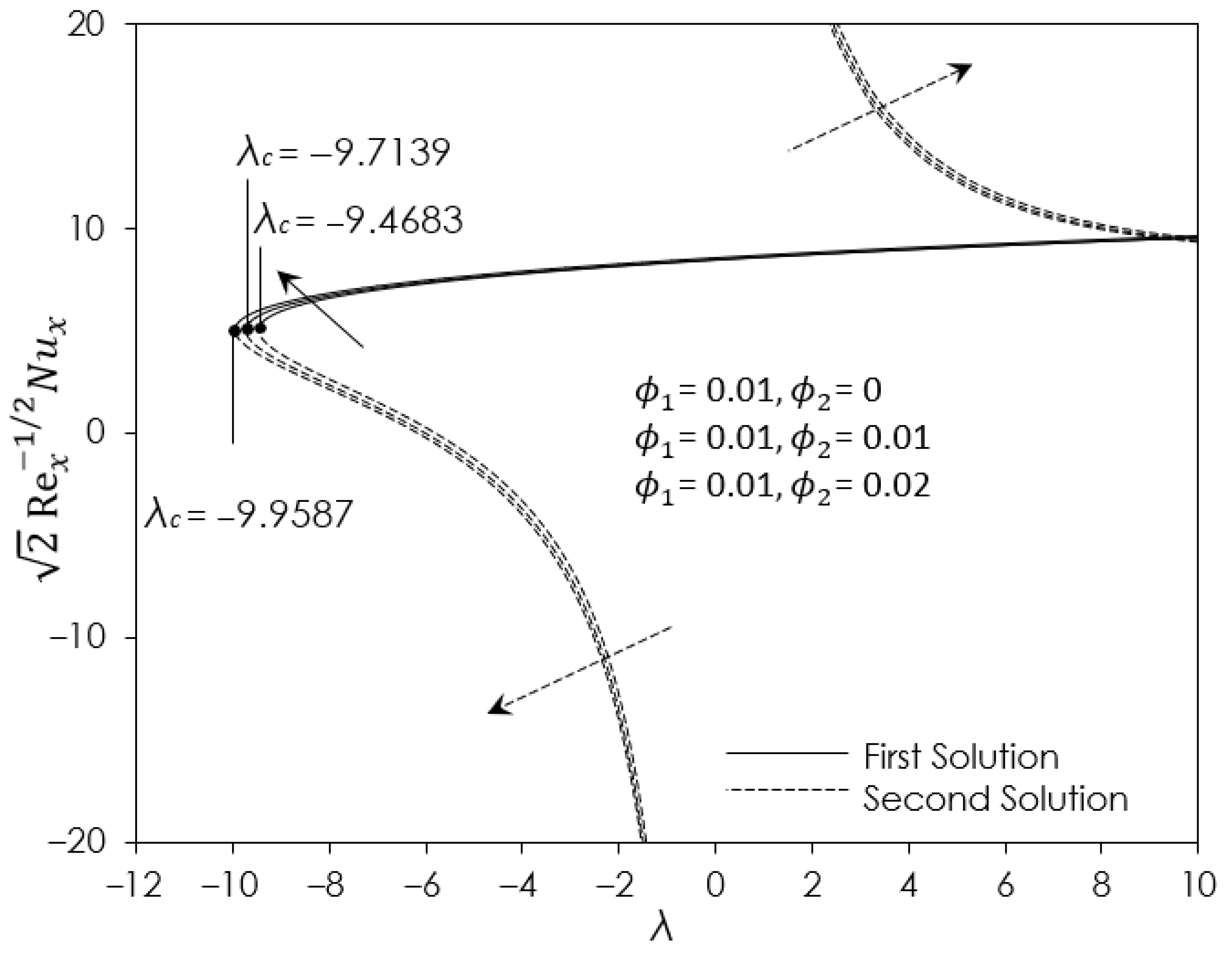
Figure 2 and Figure 3 display numerical results for the effect of several values of nanoparticle volume fraction ϕ 2 on variations of 2   Re x 1 / 2 C f and 2   Re x 1 / 2 N u x against λ . Both figures illustrate that the values 2   Re x 1 / 2 C f and 2   Re x 1 / 2 N u x for hybrid ferrofluid Fe 3 O 4 - CoFe 2 O 4 /water ( ϕ 1 = 0.01 , ϕ 2 = 0.02 ) are the highest compared to hybrid ferrofluid Fe 3 O 4 - CoFe 2 O 4 /water ( ϕ 1 = 0.01 , ϕ 2 = 0.01 ) and ferrofluid, Fe 3 O 4 /water ( ϕ 1 = 0.01 , ϕ 2 = 0 ). Physically, the presence of ϕ 2 led to a collision between two solid ferroparticles scattered in the base fluid, which led to a greater value of 2   Re x 1 / 2 C f than for one solid ferroparticle. The presence of CoFe 2 O 4 as an additional ferroparticle does influence the performance of the heat transfer rate between hybrid ferrofluid Fe 3 O 4 - CoFe 2 O 4 /water and ferrofluid Fe 3 O 4 /water. In terms of heat transfer, as in Figure 3, hybrid ferrofluid Fe 3 O 4 - CoFe 2 O 4 /water is better than ferrofluid Fe 3 O 4 /water. It is worth noticing that the increment in ϕ 2 values also contributes to the enhancement of 2   Re x 1 / 2 C f and 2   Re x 1 / 2 N u x , as portrayed in Figure 2 and Figure 3, respectively. Increasing the nanoparticle volume fraction will enhance its synergistic effect, thereby enhancing the heat transfer rate. From the observation, for assisting flow region ( λ > 0 ), the values of 2   Re x 1 / 2 C f and 2   Re x 1 / 2 N u x are greater than in the opposing flow region ( λ < 0 ). Interestingly, the existence of a dual solution can be observed in the range λ > λ c , where λ c denotes the critical value of λ . Note that the boundary layer separation occurs between the first and second solutions at λ = λ c (the point of bifurcation). It can be observed in Figure 2 and Figure 3 that the λ c for hybrid ferrofluid Fe 3 O 4 - CoFe 2 O 4 /water is lower than that for ferrofluid Fe 3 O 4 /water. This implies that hybrid ferrofluid Fe 3 O 4 - CoFe 2 O 4 /water can delay the boundary layer separation and minimize the range of solutions compared with ferrofluid Fe 3 O 4 /water.
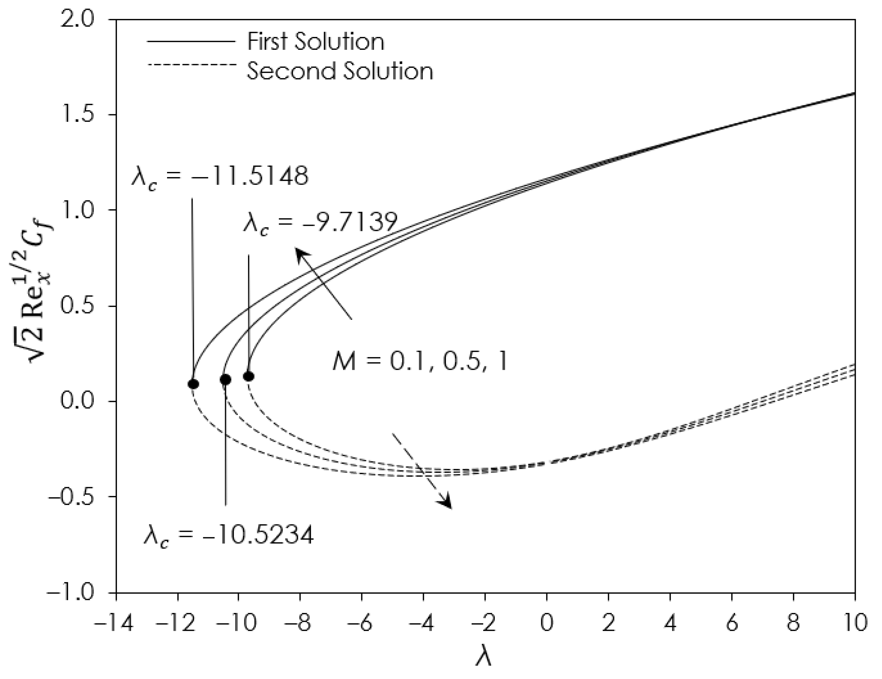
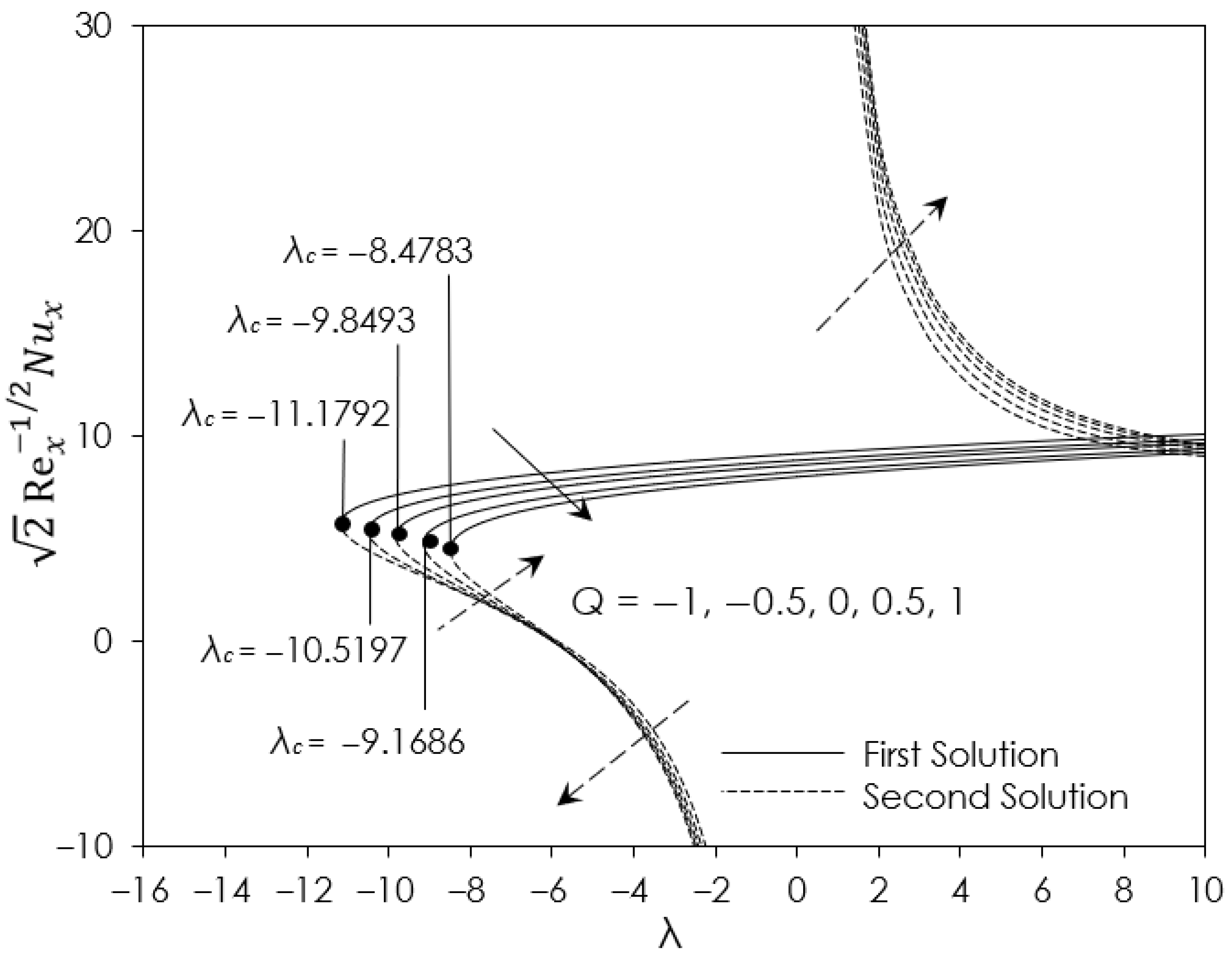
Figure 4 delineates the magnetic parameter M impact on 2   Re x 1 / 2 C f with λ . The increased value of M demonstrates the increased value for 2   Re x 1 / 2 C f . This phenomenon occurs because the presence and upsurge value of M increases the Lorentz power, otherwise called resistive sort power. This creates significantly more resistance from the flow and increases the shear stress at the wall. Other observations show the presence of M decreased the val of λ c , . which likely slows down the separation of the boundary layer. The variation of 2   Re x 1 / 2 N u x against λ with selected values of heat source Q (> 0) and heat sink Q (< 0) are portrayed in Figure 5. For the increment strength of Q (> 0), 2   Re x 1 / 2 N u x showed a decrease in value, while the increment strength of Q (< 0) caused the values of 2   Re x 1 / 2 N u x to increase. The observation on Q (> 0) indicates a reduction in heat flux because there is an increased thickness of the thermal boundary layer when there is an additional heat source in the boundary layer. Meanwhile, the heat flux was enhanced with the increment of Q (< 0) because of the reduced thickness of the thermal boundary layer. It was believed that as the strength of Q (> 0) increased, the value of λ c reduced, while as the strength of Q (< 0) increased, the value of λ c rose, as seen in Figure 5. This observation suggests that as the strength of Q (> 0) grows, it may slow down the boundary layer separation, while as the strength of Q (< 0) grows, it may accelerate the boundary layer separation.
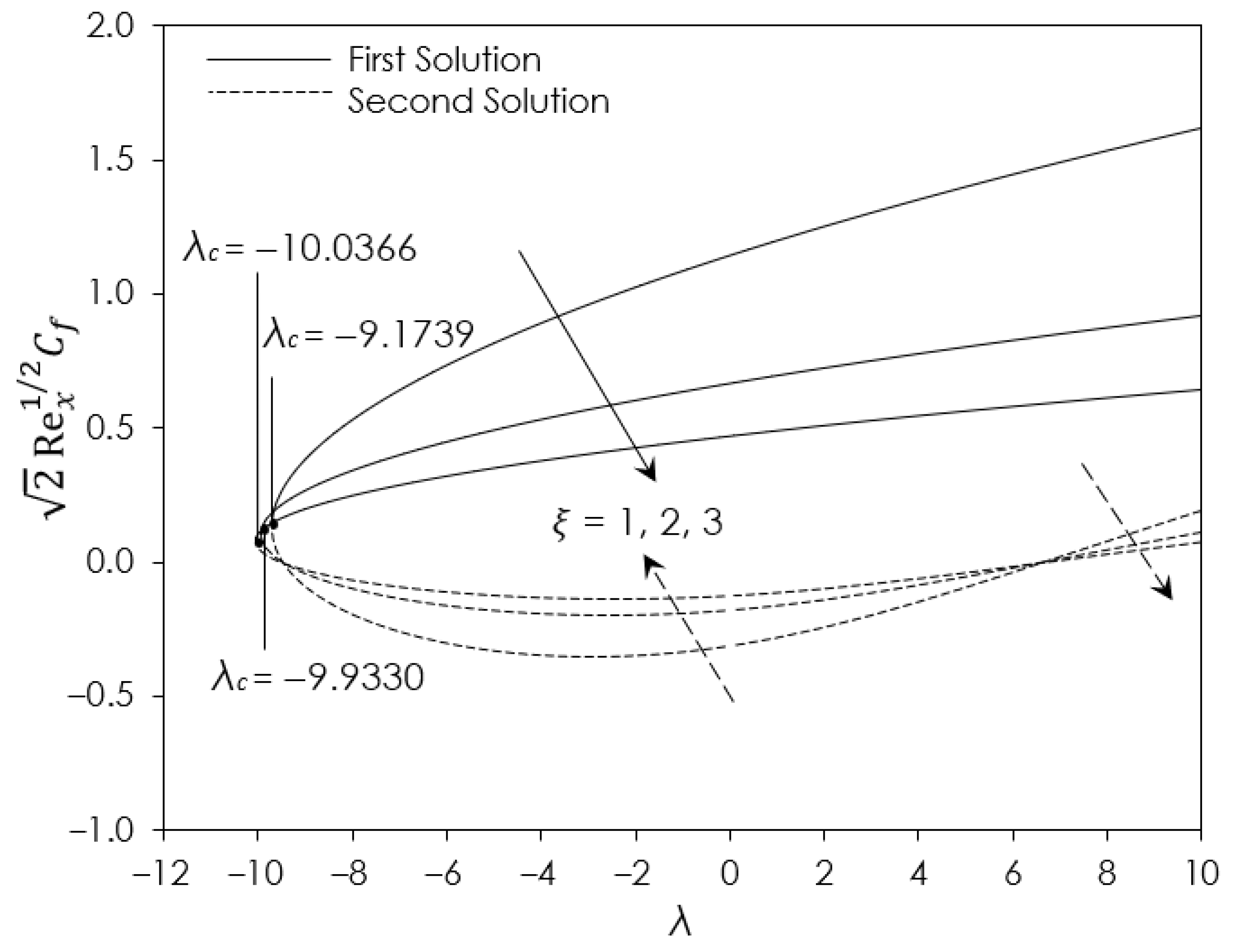
The plots of 2   Re x 1 / 2 C f against the mixed convection parameter λ with numerous values of velocity slip parameter ξ are visualized in Figure 6. The trend of 2   Re x 1 / 2 C f decreases with the escalation of ξ value for the first solution in both assisting ( λ > 0 ) and opposing flow ( λ < 0 ). In the physical aspect, the velocity slip occurs due to the finite number of molecular interactions between particles from the fluid and the wall. Generally, the fluid flow velocity is influenced by the presence of velocity slip. Here, the presence of the velocity slip parameter can be used as a controlling factor to obtain the outcome needed, whether to have a better or slower fluid flow velocity. For observation of boundary layer separation, the λ c decreased in value with the increase in ξ , allowing the conclusion that an increment of ξ may delay the boundary layer separation. Table 4 and Table 5 present the 2   Re x 1 / 2 C f and 2   Re x 1 / 2 N u x against λ for several values of shrinking parameter ( c < 0 ) and stretching parameter ( c > 0 ), respectively. The values of 2   Re x 1 / 2 C f and 2   Re x 1 / 2 N u x in assisting flow region ( λ > 0 ) are higher than in opposing flow region ( λ < 0 ) for both stretching/shrinking parameters. Additionally, the decreased value of the shrinking parameter ( c < 0 ) gives a better 2   Re x 1 / 2 C f but reduces 2   Re x 1 / 2 N u x . An observation suggests that the velocity flow will increase with the shear stress at the wall, while a reduction in heat transfer tends to occur. Meanwhile, the increased value of the stretching parameter ( c > 0 ) shows a decreasing trend value for 2   Re x 1 / 2 C f but an increase in 2   Re x 1 / 2 N u x . Here, the velocity flow tends to slow down and reduce the shear stress, while the increment of heat transfer tends to occur.
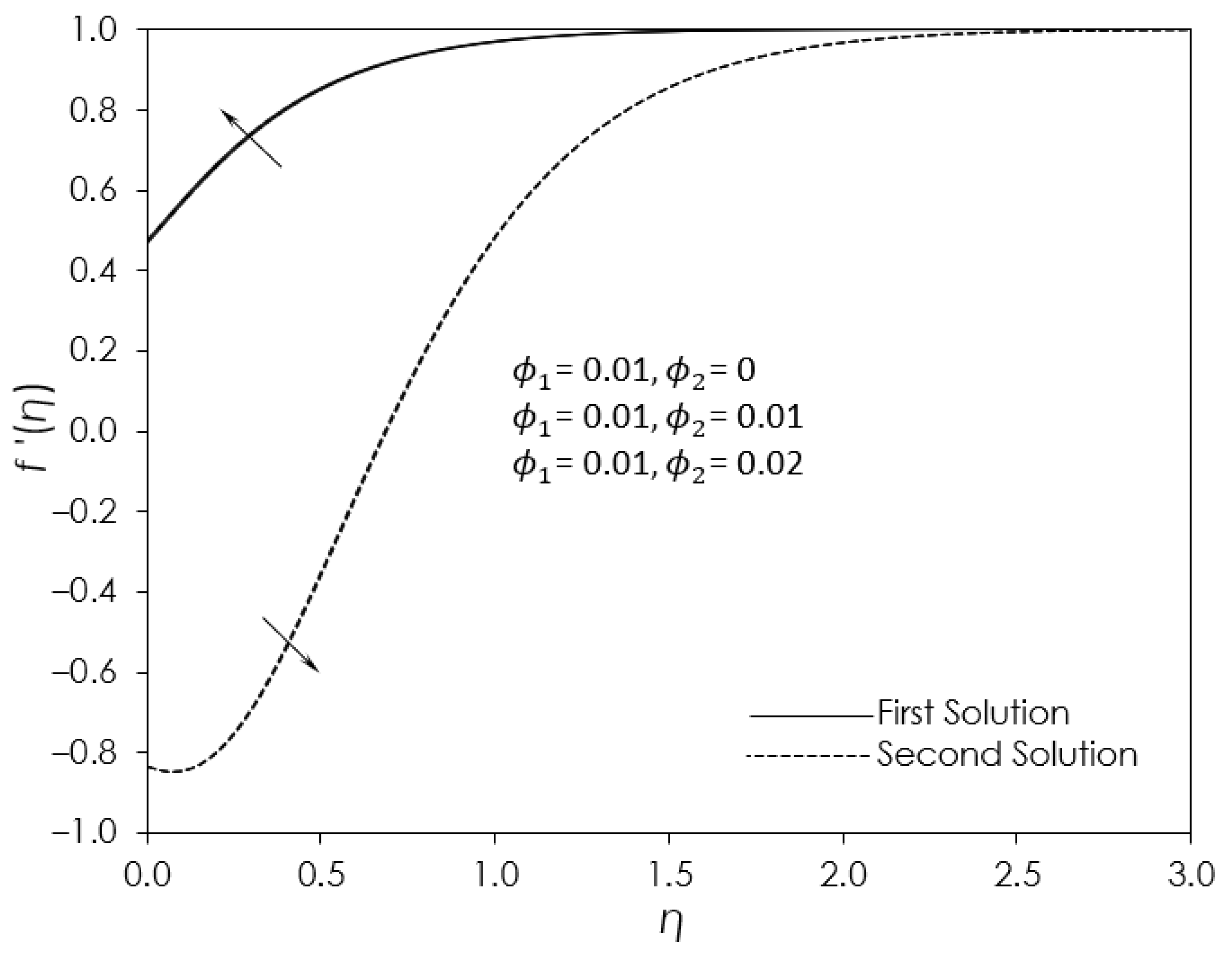
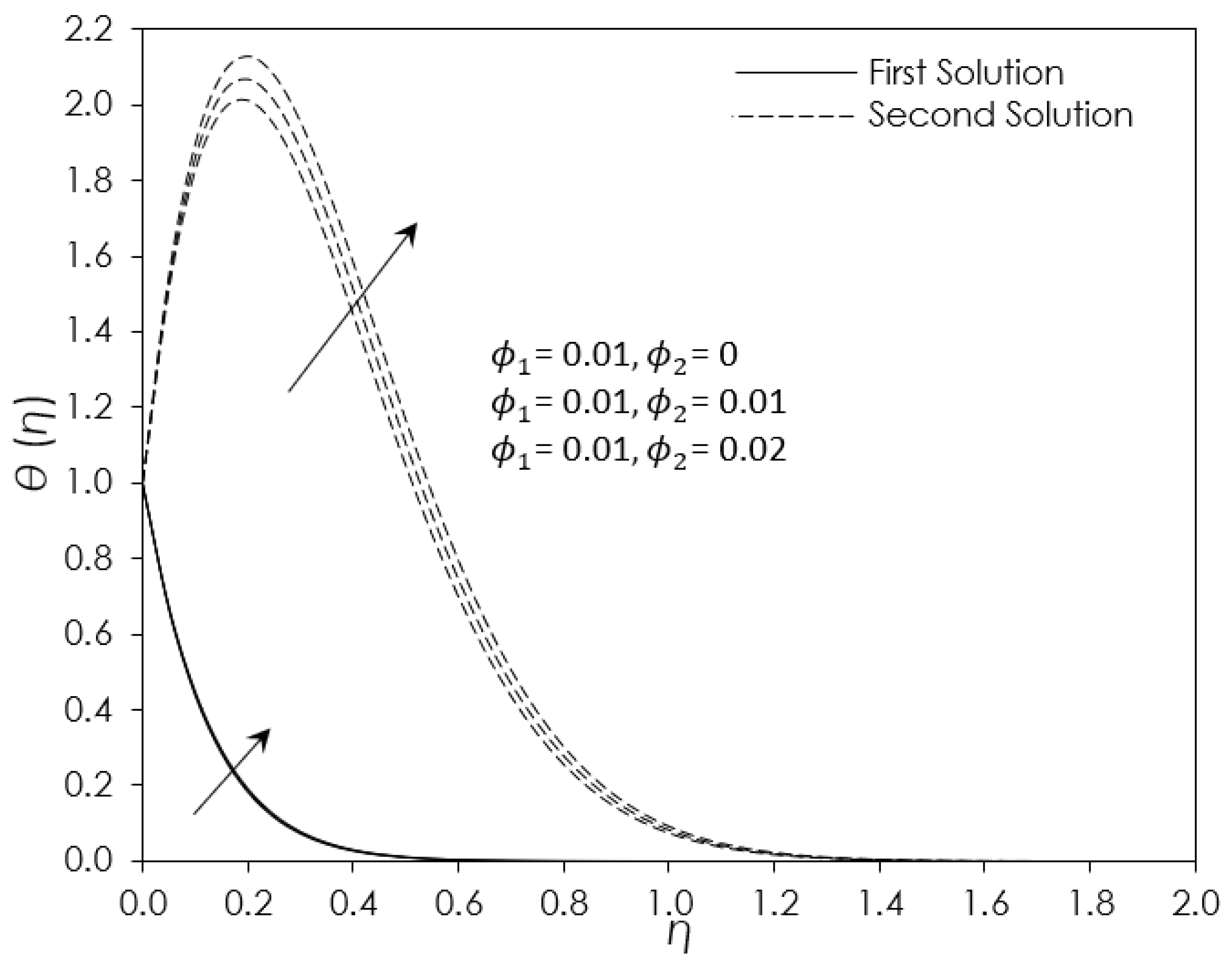
The profiles of velocity f ( η ) and temperature θ ( η ) in Figure 7 and Figure 8, respectively, highlight the influence of nanoparticle volume fraction ϕ 2 (for CoFe 2 O 4 ) in opposing flow region ( λ = 2 ) with ferrofluid Fe 3 O 4 /water ( ϕ 1 = 0.01 , ϕ 2 = 0 ), hybrid ferrofluid Fe 3 O 4 - CoFe 2 O 4 /water ( ϕ 1 = 0.01 , ϕ 2 = 0.01 ) and hybrid ferrofluid Fe 3 O 4 - CoFe 2 O 4 /water ( ϕ 1 = 0.01 , ϕ 2 = 0.02 ). Interestingly, it is depicted in Figure 7 that hybrid ferrofluid Fe 3 O 4 - CoFe 2 O 4 /water ( ϕ 1 = 0.01 , ϕ 2 = 0.02 ) has a slightly greater f ( η ) than ferrofluid Fe 3 O 4 /water ( ϕ 1 = 0.01 , ϕ 2 = 0 ) and hybrid ferrofluid Fe 3 O 4 - CoFe 2 O 4 /water ( ϕ 1 = 0.01 , ϕ 2 = 0.01 ). It is clear that the presence of ϕ 2 results in an increase in the f ( η ) but a reduction in momentum boundary layer thickness. Moreover, the increment in values of ϕ 2 yields an enhancement in f ( η ) . Physically, this will increase skin friction since the shear stress is enhanced because of the reduction in the momentum of the boundary layer thickness. This outcome is consistent with Figure 2, which shows that hybrid ferrofluid Fe 3 O 4 - CoFe 2 O 4 /water ( ϕ 1 = 0.01 , ϕ 2 = 0.02 ) has a higher 2   Re x 1 / 2 C f compared to others in opposing flow regions ( λ = 2 ) . Regarding the behavior of θ ( η ) as shown in Figure 8, ferrofluid Fe 3 O 4 /water ( ϕ 1 = 0.01 , ϕ 2 = 0 ) can be seen to have a slightly lower θ ( η ) than hybrid ferrofluid Fe 3 O 4 - CoFe 2 O 4 /water ( ϕ 1 = 0.01 , ϕ 2 = 0.01 ) and hybrid ferrofluid Fe 3 O 4 - CoFe 2 O 4 /water ( ϕ 1 = 0.01 , ϕ 2 = 0.02 ) . This discovery leads to the conclusion that the thermal boundary layer thickness concerning ferrofluid Fe 3 O 4 /water ( ϕ 1 = 0.01 , ϕ 2 = 0 ) is marginally less compared to that of the hybrid ferrofluid Fe 3 O 4 - CoFe 2 O 4 /water ( ϕ 1 = 0.01 , ϕ 2 = 0.01 ) and hybrid ferrofluid Fe 3 O 4 - CoFe 2 O 4 / water ( ϕ 1 = 0.01 , ϕ 2 = 0.02 . Physically, thinner thermal boundary layer thickness led to a larger heat flux.
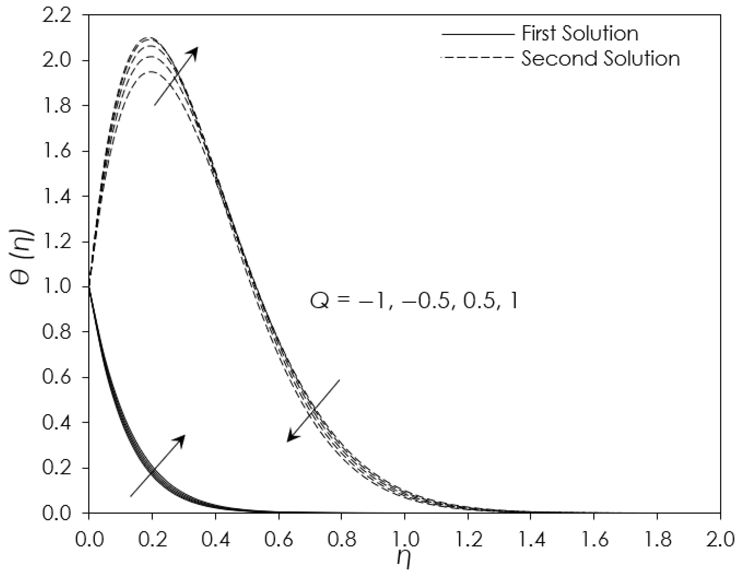
The behaviors of f ( η ) and θ ( η ) with the adjustment of the heat source Q (> 0) and heat sink Q (< 0) in opposing flow region ( λ = 2 ) are shown in Figure 9 and Figure 10, respectively. As portrayed in Figure 9, the increment in strength of heat source Q (> 0) slightly decreases the velocity profile, which in turn increases the boundary layer thickness. It slows down the fluid flow velocity, which in turn reduces the surface shear stress. As for the increment in strength of heat sink Q (< 0), it gives the converse result, which increased the velocity and shear stress while reducing boundary layer thickness. Meanwhile, the value of θ ( η ) and thermal boundary layer thickness as displayed in Figure 10 increase with the increment in strength of heat source Q (> 0), while the increased strength of heat sink Q (< 0) shows the reverse result. Here, the increment in strength of heat source Q (> 0) physically reduces the heat flux on the surface with the built-up thermal boundary layer thickness. Meanwhile, there exists a contrary statement for the increased strength of heat sink Q (< 0), where the heat flux on the surface is physically increased due to the reduction in the thermal boundary layer thickness. This result aligns with Figure 5, where the value of 2   Re x 1 / 2 N u x decreases with the increment in strength of heat source Q (> 0) while it increases with the increment in strength of heat sink Q (< 0).
The existence of a non-unique solution (dual solution) in the assisting ( λ > 0 ) and opposing flow ( λ < 0 ) region from Figure 2, Figure 3, Figure 4, Figure 5, Figure 6, Figure 7, Figure 8, Figure 9 and Figure 10 can be observed. Generally, in the range of λ > λ c , the dual solution will appear. A unique solution where the first and second solution meet is known as the critical value λ c . Point λ = λ c is known as a point of bifurcation of first and second solutions. Separation for the boundary layer occurs when λ = λ c , and using boundary layer approximation, no solution is obtained if the range is between λ < λ c . Therefore, it is necessary to perform the flow’s stability analysis. In order to execute the stability analysis, the same numerical approach was used for solving the linearized equations (25)–(27) numerically, as discussed in the previous section. It is essential to obtain small eigenvalues γ for verification of stability analysis. Here, Table 6 was constructed to demonstrate the behavior of small eigenvalues γ when M = 0.1, Q = 1, c = −0.5, ξ = 0.1, and of hybrid ferrofluids ( ϕ 1 = 0.01, ϕ 2 = 0.01) concerning λ . According to [66] and [67], the first solution gives a positive value for eigenvalue γ 1 , which implies the initial decay of disturbance for real and stable flow as time passes. Meanwhile, the negative value of the eigenvalue γ 2 from the second solution implies initial growth of disturbance for unreal and unstable flow as time passes. It can be seen from Table 6 that as mixed convection parameter λ approaches the critical values λ c , the values of small eigenvalues γ 1 and γ 2 approach zero. This allows the conclusion that the first solution is in a stable state, while the second solution is in an unstable state.

5. Conclusion

This study investigated the steady mixed convection in hybrid ferrofluid flow past an exponentially shrinking/stretching surface in a stagnation-point area. The governing equations were solved numerically by applying MATLAB’s built-in solver (bvp4c). The influence of variation of governing parameters such as nanoparticle volume fraction, velocity slip parameter, magnetic parameter, heat source/sink parameter, and stretching/shrinking parameter were discussed in detail. Here, the significant outcomes can be summarized as follows:
  • The appearance of a non-unique solution or dual solution for a certain governing parameter in both assisting flow and opposing flow. The bifurcation point occurs at the opposing flow region.
  • The stability analysis results show a stable first solution and an unstable second solution.
  • The increment of nanoparticle volume fraction ϕ 2 ( CoFe 2 O 4 ) increases heat transfer and skin friction.
  • The addition of CoFe 2 O 4 nanoparticle to hybrid ferrofluid Fe 3 O 4 - CoFe 2 O 4 /water enhances the heat transfer rate better than ferrofluid Fe 3 O 4 /water due to the collision between two nanoparticles enhancing the synergistic effects.
  • The influence of the magnetic field M enhanced the fluid flow velocity due to the presence of Lorentz forces in flow and slowing down the boundary layer separation.
  • The increased strength of the heat source ( Q > 0 ) reduced the heat transfer efficiency because of the larger thermal boundary layer thickness due to the additional external heat sources. Meanwhile, the increased strength of the heat sink ( Q < 0 ) yields the reverse result, which in turn reduced thermal boundary layer thickness due to the heat loss for the heat sink.
  • The presence of velocity slip ξ reduced the flow velocity and delayed the boundary layer separation.
  • The increment of stretching parameter ( c > 0 ) reduced the skin friction value, which slows down the fluid flow velocity. Meanwhile, the increment of shrinking parameter ( c < 0 ) increases the skin friction value, which accelerates the fluid flow velocity.
  • In terms of heat transfer, the increment of stretching parameter ( c > 0 ) gives a better value of the Nusselt number, while the increment of shrinking parameter ( c < 0 ) gives a reverse result.

Author Contributions

S.Z., A.J., R.N. and I.P. modelled the problem, numerically computed results, discussed the results, computed the tabulated results, wrote the manuscript and proofread it. All authors have read and agreed to the published version of the manuscript.

Funding

This research was funded by Ministry of Higher Education, grant number [FRGS/1/2020/STG06/UPNM/03/1] and Universiti Kebangsaan Malaysia (UKM), grant number [ST-2022-015].

Data Availability Statement

Not applicable.

Acknowledgments

The authors are thankful to the honorable reviewers for their constructive suggestions to improve the quality of the paper. The authors from the Universiti Pertahanan Nasional Malaysia would like to acknowledge the research grant form Ministry of Higher Education (grant number: FRGS/1/2020/STG06/UPNM/03/1) and the author from the Universiti Kebangsaan Malaysia (UKM) would like to express her sincere thanks to the Universiti Kebangsaan Malaysia (UKM) for funding this research work from the grant ST-2022-015.

Conflicts of Interest

The authors declare no conflict of interest.

References

  1. Choi, S.U.; Eastman, J.A. Enhancing Thermal Conductivity of Fluids with Nanoparticles. ASME Publ. Fed. 1995, 231, 99–106. [Google Scholar]
  2. Saidur, R.; Leong, K.Y.; Mohammed, H.A. A review on applications and challenges of nanofluids. Renew. Sustain. Energy Rev. 2011, 15, 1646–1668. [Google Scholar] [CrossRef]
  3. Sidik, N.A.C.; Adamu, I.M.; Jamil, M.M.; Kefayati, G.H.R.; Mamat, R.; Najafi, G. Recent progress on hybrid nanofluids in heat transfer applications: A comprehensive review. Int. Commun. Heat Mass Transf. 2016, 78, 68–79. [Google Scholar] [CrossRef]
  4. Sidik, N.A.C.; Jamil, M.M.; Japar, W.M.A.A.; Adamu, I.M. A review on preparation methods, stability and applications of hybrid nanofluids. Renew. Sustain. Energy Rev. 2017, 80, 1112–1122. [Google Scholar] [CrossRef]
  5. Zulkifli, S.N.; Sarif, N.M.; Salleh, M.Z. Numerical solution of boundary layer flow over a moving plate in a nanofluid with viscous dissipation: A revised model. J. Adv. Res. Fluid Mech. Therm. Sci. 2019, 56, 287–295. [Google Scholar]
  6. Al-Rashed, A.A.; Sheikhzadeh, G.A.; Aghaei, A.; Monfared, F.; Shahsavar, A.; Afrand, M. Effect of a porous medium on flow and mixed convection heat transfer of nanofluids with variable properties in a trapezoidal enclosure. J. Therm. Anal. Calorim. 2020, 139, 741–754. [Google Scholar] [CrossRef]
  7. Ferdows, M.; Shamshuddin, M.D.; Salawu, S.O.; Zaimi, K. Numerical simulation for the steady nanofluid boundary layer flow over a moving plate with suction and heat generation. SN Appl. Sci. 2021, 3, 1–11. [Google Scholar] [CrossRef]
  8. Waini, I.; Ishak, A.; Pop, I. Nanofluid flow on a shrinking cylinder with Al2O3 nanoparticles. Mathematics 2021, 9, 1612. [Google Scholar] [CrossRef]
  9. Rosenweig, R.E. Magnetic fluids. Annu. Rev. Fluid Mech. 1987, 19, 437–463. [Google Scholar] [CrossRef]
  10. Bahiraei, M.; Hangi, M. Flow and heat transfer characteristics of magnetic nanofluids: A review. J. Magn. Magn. Mater. 2015, 374, 125–138. [Google Scholar] [CrossRef]
  11. Pîslaru-Danescu, L.; Morega, A.M.; Morega, M.; Stoica, V.; Marinica, O.M.; Nouras, F.; Paduraru, N.; Borbath, I.; Borbath, T. Prototyping a ferrofluid-cooled transformer. IEEE Trans. Ind. Appl. 2013, 49, 1289–1298. [Google Scholar] [CrossRef]
  12. Zhang, X.; Sun, L.; Yu, Y.; Zhao, Y. Flexible ferrofluids: Design and applications. Adv. Mater. 2019, 31, 1903497. [Google Scholar] [CrossRef] [PubMed]
  13. Mohamed, M.K.A.; Abas, F.N.; Salleh, M.Z. MHD boundary layer flow over a permeable flat plate in a ferrofluid with thermal radiation effect. J. Phys. Conf. Ser. 2019, 1366, 012014. [Google Scholar] [CrossRef] [Green Version]
  14. El-Kabeir, S.M.M.; El-Zahar, E.R.; Modather, M.; Gorla, R.S.R.; Rashad, A.M. Unsteady MHD slip flow of a ferrofluid over an impulsively stretched vertical surface. AIP Adv. 2019, 9, 045112. [Google Scholar] [CrossRef] [Green Version]
  15. Jamaludin, A.; Naganthran, K.; Nazar, R.; Pop, I. Thermal radiation and MHD effects in the mixed convection flow of Fe3O4-water ferrofluid towards a nonlinearly moving surface. Processes 2020, 8, 95. [Google Scholar] [CrossRef] [Green Version]
  16. Mehrez, Z.; El Cafsi, A. Heat exchange enhancement of ferrofluid flow into rectangular channel in the presence of a magnetic field. Appl. Math. Comput. 2021, 391, 125634. [Google Scholar] [CrossRef]
  17. Hamid, R.A.; Nazar, R.; Naganthran, K.; Pop, I. Effects of Magnetic Fields, Coupled Stefan Blowing and Thermodiffusion on Ferrofluid Transport Phenomena. Mathematics 2022, 10, 1646. [Google Scholar] [CrossRef]
  18. Kumar, K.A.; Sandeep, N.; Sugunamma, V.; Animasaun, I.L. Effect of irregular heat source/sink on the radiative thin film flow of MHD hybrid ferrofluid. J. Therm. Anal. Calorim. 2020, 139, 2145–2153. [Google Scholar] [CrossRef]
  19. Tlili, I.; Mustafa, M.T.; Kumar, K.A.; Sandeep, N. Effect of asymmetrical heat rise/fall on the film flow of magnetohydrodynamic hybrid ferrofluid. Sci. Rep. 2020, 10, 6677. [Google Scholar] [CrossRef] [Green Version]
  20. Manh, T.D.; Khan, A.R.; Shafee, A.; Nam, N.D.; Tlili, I.; Nguyen-Thoi, T.; Li, Z. Hybrid nanoparticles migration due to MHD free convection considering radiation effect. Phys. A Stat. Mech. Its Appl. 2020, 551, 124042. [Google Scholar] [CrossRef]
  21. Giwa, S.O.; Sharifpur, M.; Meyer, J.P. Effects of uniform magnetic induction on heat transfer performance of aqueous hybrid ferrofluid in a rectangular cavity. Appl. Therm. Eng. 2020, 170, 115004. [Google Scholar] [CrossRef]
  22. Anuar, N.S.; Bachok, N.; Pop, I. Influence of MHD Hybrid Ferrofluid Flow on Exponentially Stretching/Shrinking Surface with Heat Source/Sink under Stagnation Point Region. Mathematics 2021, 9, 2932. [Google Scholar] [CrossRef]
  23. Sparrow, E.M.; Eichhorn, R.; Gregg, J.L. Combined forced and free convection in a boundary layer flow. Phys. Fluids 1959, 2, 319–328. [Google Scholar] [CrossRef]
  24. Ramachandran, N.; Chen, T.S.; Armaly, B.F. Mixed convection in stagnation flows adjacent to vertical surfaces. ASME J. Heat Mass Transf. 1988, 110, 373–377. [Google Scholar] [CrossRef]
  25. Tiwari, R.K.; Das, M.K. Heat transfer augmentation in a two-sided lid-driven differentially heated square cavity utilizing nanofluids. Int. J. Heat Mass Transf. 2007, 50, 2002–2018. [Google Scholar] [CrossRef]
  26. Yashkun, U.; Zaimi, K.; Ishak, A.; Pop, I.; Sidaoui, R. Hybrid nanofluid flow through an exponentially stretching/shrinking sheet with mixed convection and Joule heating. Int. J. Numer. Methods Heat Fluid Flow 2020, 31, 1930–1950. [Google Scholar] [CrossRef]
  27. Lund, L.A.; Lashin, M.; Yashkun, U.; Guedri, K.; Khan, S.U.; Khan, M.I.; Kumam, P. Thermal stable properties of solid hybrid nanoparticles for mixed convection flow with slip features. Sci. Rep. 2022, 12, 16447. [Google Scholar] [CrossRef]
  28. Hayat, T.; Fetecau, C.; Sajid, M. Analytic solution for MHD transient rotating flow of a second grade fluid in a porous space. Nonlinear Anal. Real World Appl. 2008, 9, 1619–1627. [Google Scholar] [CrossRef]
  29. Khan, A.Q.; Rasheed, A. Mixed convection magnetohydrodynamics flow of a nanofluid with heat transfer: A numerical study. Math. Probl. Eng. 2019, 2019, 8129564. [Google Scholar] [CrossRef] [Green Version]
  30. Wahid, N.S.; Arifin, N.M.; Khashi’ie, N.S.; Pop, I.; Bachok, N.; Hafidzuddin, M.E.H. MHD mixed convection flow of a hybrid nanofluid past a permeable vertical flat plate with thermal radiation effect. Alex. Eng. J. 2022, 61, 3323–3333. [Google Scholar] [CrossRef]
  31. Sivasankaran, S.; Niranjan, H.; Bhuvaneswari, M. Chemical reaction, radiation and slip effects on MHD mixed convection stagnation-point flow in a porous medium with convective boundary condition. Int. J. Numer. Methods Heat Fluid Flow 2017, 27, 454–470. [Google Scholar] [CrossRef]
  32. Patil, P.M.; Kulkarni, M. Analysis of MHD mixed convection in a Ag-TiO2 hybrid nanofluid flow past a slender cylinder. Chin. J. Phys. 2021, 73, 406–419. [Google Scholar] [CrossRef]
  33. Lone, S.A.; Alyami, M.A.; Saeed, A.; Dawar, A.; Kumam, P.; Kumam, W. MHD micropolar hybrid nanofluid flow over a flat surface subject to mixed convection and thermal radiation. Sci. Rep. 2022, 12, 17283. [Google Scholar] [CrossRef] [PubMed]
  34. Zainal, N.A.; Nazar, R.; Naganthran, K.; Pop, I. MHD mixed convection stagnation point flow of a hybrid nanofluid past a vertical flat plate with convective boundary condition. Chin. J. Phys. 2020, 66, 630–644. [Google Scholar] [CrossRef]
  35. Sharma, P.R.; Sinha, S.; Yadav, R.S.; Filippov, A.N. MHD mixed convective stagnation point flow along a vertical stretching sheet with heat source/sink. Int. J. Heat Mass Transf. 2018, 117, 780–786. [Google Scholar] [CrossRef]
  36. Jamaludin, A.; Nazar, R.; Pop, I. Mixed convection stagnation-point flow of a nanofluid past a permeable stretching/shrinking sheet in the presence of thermal radiation and heat source/sink. Energies 2019, 12, 788. [Google Scholar] [CrossRef] [Green Version]
  37. Jamaludin, A.; Naganthran, K.; Nazar, R.; Pop, I. MHD mixed convection stagnation-point flow of Cu-Al2O3/water hybrid nanofluid over a permeable stretching/shrinking surface with heat source/sink. Eur. J. Mech. B Fluids 2020, 84, 71–80. [Google Scholar] [CrossRef]
  38. Armaghani, T.; Sadeghi, M.S.; Rashad, A.M.; Mansour, M.A.; Chamkha, A.J.; Dogonchi, A.S.; Nabwey, H.A. MHD mixed convection of localized heat source/sink in an Al2O3-Cu/water hybrid nanofluid in L-shaped cavity. Alex. Eng. J. 2021, 60, 2947–2962. [Google Scholar] [CrossRef]
  39. Zainal, N.A.; Naganthran, K.; Nazar, R. Unsteady MHD Rear Stagnation-Point Flow of a Hybrid Nanofluid with Heat Generation/Absorption Effect. J. Adv. Res. Fluid Mech. Therm. Sci. 2021, 87, 41–51. [Google Scholar] [CrossRef]
  40. Agrawal, P.; Dadheech, P.K.; Jat, R.N.; Baleanu, D.; Purohit, S.D. Radiative MHD hybrid-nanofluids flow over a permeable stretching surface with heat source/sink embedded in porous medium. Int. J. Numer. Methods Heat Fluid Flow 2021, 31, 2818–2840. [Google Scholar] [CrossRef]
  41. Yaseen, M.; Kumar, M.; Rawat, S.K. Assisting and opposing flow of a MHD hybrid nanofluid flow past a permeable moving surface with heat source/sink and thermal radiation. Part. Differ. Equ. Appl. Math. 2021, 4, 100168. [Google Scholar] [CrossRef]
  42. Sneha, K.N.; Mahabaleshwar, U.S.; Bhattacharyya, S. An effect of thermal radiation on inclined MHD flow in hybrid nanofluids over a stretching/shrinking sheet. J. Therm. Anal. Calorim. 2022. [Google Scholar] [CrossRef]
  43. Karwe, M.V.; Jaluria, Y. Numerical simulation of thermal transport associated with a continuously moving flat sheet in materials processing. J. Heat Transf. 1991, 113, 612–619. [Google Scholar] [CrossRef]
  44. Sakiadis, B.C. Boundary-layer behavior on continuous solid surfaces: I. Boundary-layer Equations for two-dimensional and axisymmetric flow. AICHE J. 1961, 7, 26–28. [Google Scholar] [CrossRef]
  45. Crane, L.J. Flow past a stretching plate. Z. Für Angew. Math. Phys. ZAMP 1970, 21, 645–647. [Google Scholar] [CrossRef]
  46. Magyari, E.; Keller, B. Heat and mass transfer in the boundary layers on an exponentially stretching continuous surface. J. Phys. D Appl. Phys. 1999, 32, 577. [Google Scholar] [CrossRef]
  47. Elbashbeshy, E.M.A. Heat transfer over an exponentially stretching continuous surface with suction. Arch. Mech. 2001, 53, 643–651. [Google Scholar]
  48. Anuar, N.S.; Bachok, N.; Arifin, N.M.; Rosali, H. Effect of suction/injection on stagnation point flow of hybrid nanofluid over an exponentially shrinking sheet with stability analysis. CFD Lett. 2019, 11, 21–33. [Google Scholar]
  49. Patil, P.M.; Latha, D.N.; Chamkha, A.J. Non-similar Solutions of MHD Mixed Convection over an Exponentially Stretching Surface: Influence of Non-uniform Heat Source or Sink. J. Appl. Comput. Mech. 2021, 7, 1334–1347. [Google Scholar]
  50. Waini, I.; Ishak, A.; Pop, I. Hybrid nanofluid flow towards a stagnation point on an exponentially stretching/shrinking vertical sheet with buoyancy effects. Int. J. Numer. Methods Heat Fluid Flow 2020, 31, 216–235. [Google Scholar] [CrossRef]
  51. Zainal, N.A.; Nazar, R.; Naganthran, K.; Pop, I. Viscous dissipation and MHD hybrid nanofluid flow towards an exponentially stretching/shrinking surface. Neural Comput. Appl. 2021, 33, 11285–11295. [Google Scholar] [CrossRef]
  52. Jamaludin, A.; Nazar, R.; Naganthran, K.; Pop, I. Mixed convection hybrid nanofluid flow over an exponentially accelerating surface in a porous media. Neural Comput. Appl. 2021, 33, 15719–15729. [Google Scholar] [CrossRef]
  53. Hatzikiriakos, S.G. Slip mechanisms in complex fluid flows. Soft Matter. 2015, 11, 7851–7856. [Google Scholar] [CrossRef] [PubMed]
  54. Khader, M.M.; Megahed, A.M. Numerical solution for boundary layer flow due to a nonlinearly stretching sheet with variable thickness and slip velocity. Eur. Phys. J. Plus 2013, 128, 100. [Google Scholar] [CrossRef]
  55. Hafidzuddin, E.H.; Nazar, R.; Arifin, N.M.; Pop, I. Effects of anisotropic slip on three-dimensional stagnation-point flow past a permeable moving surface. Eur. J. Mech. B Fluids 2017, 65, 515–521. [Google Scholar] [CrossRef]
  56. Navier, C.L. Memorie sur les lois du lois du mouvement des fluides. Mem. Acad. Sci. Inst. Fr. 1827, 6, 298–440. [Google Scholar]
  57. Maxwell, J.C., III. On stresses in rarefied gases arising from inequalities of temperature. Proc. R. Soc. Lond. 1878, 27, 304–308. [Google Scholar]
  58. Rao, I.J.; Rajagopal, K.R. The effect of the slip boundary condition on the flow of fluids in a channel. Acta Mech. 1999, 135, 113–126. [Google Scholar] [CrossRef]
  59. Anuar, N.S.; Bachok, N.; Arifin, N.M.; Rosali, H. Mixed Convection Flow and Heat Transfer of Carbon Nanotubes Over an Exponentially Stretching/Shrinking Sheet with Suction and Slip Effect. J. Adv. Res. Fluid Mech. Therm. Sci. 2019, 59, 232–242. [Google Scholar]
  60. Ghosh, S.; Mukhopadhyay, S. Stability analysis for model-based study of nanofluid flow over an exponentially shrinking permeable sheet in presence of slip. Neural Comput. Appl. 2020, 32, 7201–7211. [Google Scholar] [CrossRef]
  61. Yan, L.; Dero, S.; Khan, I.; Mari, I.A.; Baleanu, D.; Nisar, K.S.; Sherif, E.-S.M.; Abdo, H.S. Dual solutions and stability analysis of magnetized hybrid nanofluid with joule heating and multiple slip conditions. Processes 2020, 8, 332. [Google Scholar] [CrossRef] [Green Version]
  62. Abu Bakar, S.; Md Arifin, N.; Khashi’ie, N.S.; Bachok, N. Hybrid Nanofluid Flow over a Permeable Shrinking Sheet Embedded in a Porous Medium with Radiation and Slip Impacts. Mathematics 2021, 9, 878. [Google Scholar] [CrossRef]
  63. Yatsyshin, P.; Kalliadasis, S. Coupled Mathematical Models for Physical and Biological Nanoscale Systems and Their Applications; Springer: Basel, Switzerland, 2018; pp. 171–185. [Google Scholar]
  64. Ha, S.N. A nonlinear shooting method for two-point boundary value problems. Comput. Math. Appl. 2001, 42, 1411–1420. [Google Scholar] [CrossRef] [Green Version]
  65. Shampine, L.F.; Shampine, L.F.; Gladwell, I.; Thompson, S. Solving ODEs with Matlab; Cambridge University Press: Cambridge, UK, 2003. [Google Scholar]
  66. Merkin, J.H. On dual solutions occurring in mixed convection in a porous medium. J. Eng. Math. 1986, 20, 171–179. [Google Scholar] [CrossRef]
  67. Weidman, P.; Turner, M.R. Stagnation-point flows with stretching surfaces: A unified formulation and new results. Eur. J. Mech. B Fluids 2017, 61, 144–153. [Google Scholar] [CrossRef] [Green Version]
  68. Pang, C.; Jung, J.Y.; Kang, Y.T. Aggregation based model for heat conduction mechanism in nanofluids. Int. J. Heat Mass Transf. 2014, 72, 392–399. [Google Scholar] [CrossRef]
  69. Ebrahimi, A.; Rikhtegar, F.; Sabaghan, A.; Roohi, E. Heat transfer and entropy generation in a microchannel with longitudinal vortex generators using nanofluids. Energy 2016, 101, 190–201. [Google Scholar] [CrossRef]
  70. Devi, S.A.; Devi, S.S.U. Numerical investigation of hydromagnetic hybrid Cu-Al2O3/water nanofluid flow over a permeable stretching sheet with suction. Int. J. Nonlinear Sci. Numer. Simul. 2016, 17, 249–257. [Google Scholar] [CrossRef]
  71. Bachok, N.; Ishak, A.; Pop, I. Boundary layer stagnation-point flow and heat transfer over an exponentially stretching/shrinking sheet in a nanofluid. Int. J. Heat Mass Transf. 2012, 55, 8122–8128. [Google Scholar] [CrossRef]
  72. Rehman, F.U.; Nadeem, S.; Rehman, H.U.; Haq, R.U. Thermophysical analysis for three-dimensional MHD stagnation-point flow of nano-material influenced by an exponential stretching surface. Results Phys. 2018, 8, 316–323. [Google Scholar] [CrossRef]
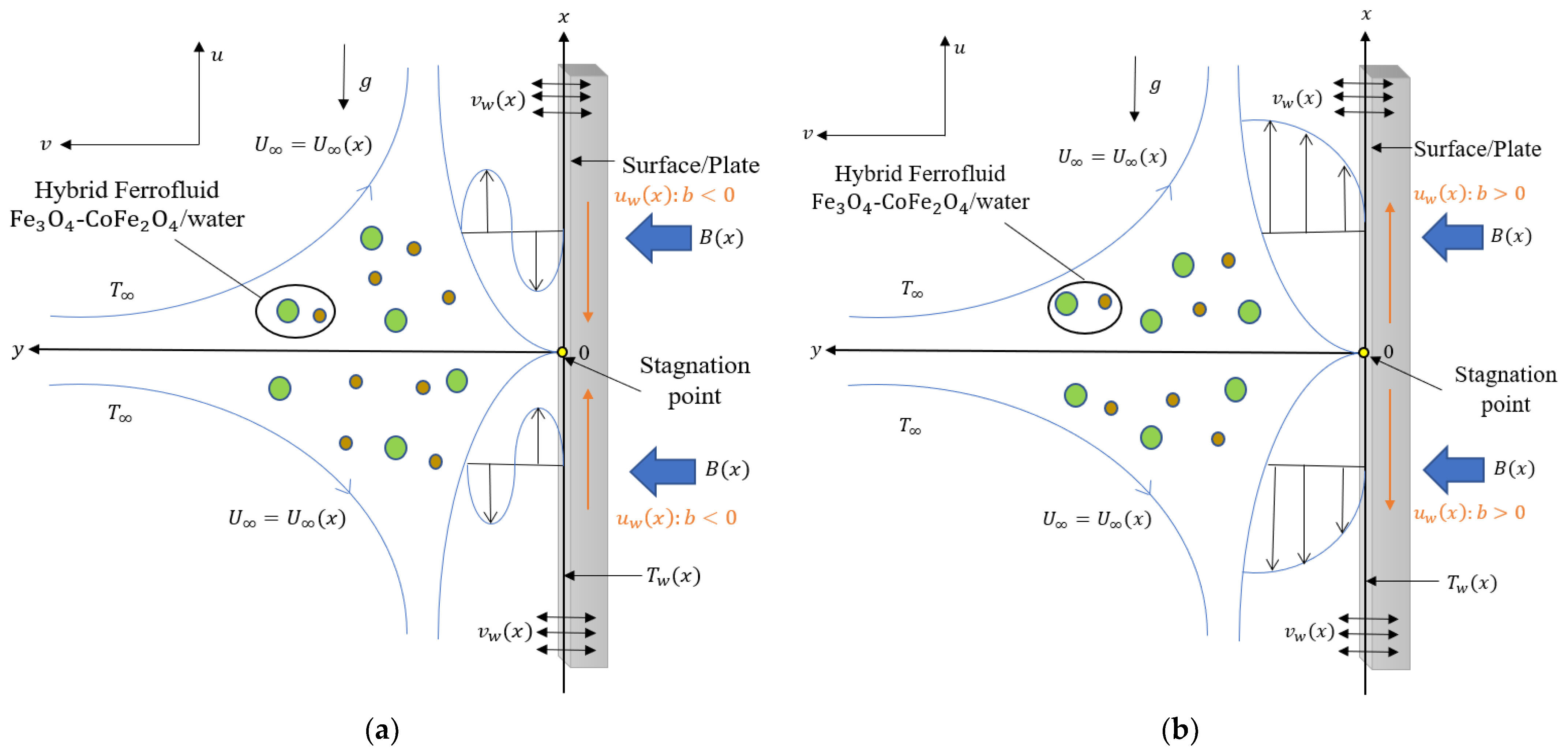
Figure 1. Physical Model. (a) Shrinking b < 0 . (b) Stretching b > 0 .
Mathematics 10 04400 g001
Figure 2. Variation of 2   Re x 1 / 2 C f for different values of ϕ 2 .
Mathematics 10 04400 g002
Figure 3. Variation of 2   Re x 1 / 2 N u x for different values of ϕ 2 .
Mathematics 10 04400 g003
Figure 4. Variation of 2   Re x 1 / 2 C f for different values of M .
Mathematics 10 04400 g004
Figure 5. Variation of 2   Re x 1 / 2 N u x for different values of Q .
Mathematics 10 04400 g005
Figure 6. Variation of 2   Re x 1 / 2 C f for different values of ξ .
Mathematics 10 04400 g006
Figure 7. Variation of f ( η ) for different values of ϕ 2 .
Mathematics 10 04400 g007
Figure 8. Variation of θ ( η ) for different values of ϕ 2 .
Mathematics 10 04400 g008
Figure 9. Variation of f ( η ) for different values of Q .
Mathematics 10 04400 g009
Figure 10. Variation of θ ( η ) for different values of Q .
Mathematics 10 04400 g010
Table 1. Theoretical models for properties of the ferrofluid and hybrid ferrofluids [37,50,70].
PropertiesFerrofluidHybrid Ferrofluids
Viscosity μ n f = μ f ( 1 ϕ ) 2.5 μ h n f = μ f ( 1 ϕ 1 ) 2.5 ( 1 ϕ 2 ) 2.5
Density ρ n f = ( 1 ϕ 1 ) ρ f + ϕ 1 ρ s 1 ρ h n f = ( 1 ϕ 2 ) [ ( 1 ϕ 1 ) ρ f + ϕ 1 ρ s 1 ] + ϕ 2 ρ s 2
Electrical Conductivity σ n f σ f = 1 + 3 ( σ s 1 / σ f 1 ) ϕ 1 σ s 1 / σ f + 2 ( σ s 1 / σ f 1 ) ϕ 1 σ h n f σ n f = σ s 2 + 2 σ n f 2 ϕ 2 ( σ n f σ s 2 ) σ s 2 + 2 σ n f + ϕ 2 ( σ n f σ s 2 )
where
σ n f σ f = σ s 1 + 2 σ f 2 ϕ 1 ( σ f σ s 1 ) σ s 1 + 2 σ f + ϕ 1 ( σ f σ s 1 )
Thermal Diffusivity α n f = k n f ( ρ C p ) n f α h n f = k h n f ( ρ C p ) h n f
Thermal Expansion Coefficient ( ρ β ) n f = ( 1 ϕ 1 ) ( ρ β ) f + ϕ 1 ( ρ β ) s 1 ( ρ β ) h n f = ( 1 ϕ 2 ) [ ( 1 ϕ 1 ) ( ρ β ) f + ϕ 1 ( ρ β ) s 1 ] + ϕ 2 ( ρ β ) s 2
Heat Capacity ( ρ C p ) n f = ( 1 ϕ 1 ) ( ρ C p ) f + ϕ 1 ( ρ C p ) s 1 ( ρ C p ) h n f = ( 1 ϕ 2 ) [ ( 1 ϕ 1 ) ( ρ C p ) f + ϕ 1 ( ρ C p ) s 1 ] + ϕ 2 ( ρ C p ) s 2
Table 2. Thermophysical properties of ferroparticles and water (base fluid) [13,18].
Thermophysical Properties F e 3 O 4 C o F e 2 O 4 H 2 O
C p ( J k g 1 K 1 ) 6707004179
ρ ( k g m 3 ) 51804907997.1
k ( W m 1 K 1 ) 9.73.70.613
β × 10 5 ( K 1 ) 1.31.321
σ ( S m 1 ) 0.74 × 10 6 1.1 × 10 7 5.5 × 10 6
Table 3. Comparison values of 2   Re x 1 / 2 C f and 2   Re x 1 / 2 N u x for Al 2 O 3 /water ( ϕ 2 = 0 ) with various values of c and ϕ 1 when λ = 0 , Pr = 6.2.
2   R e x 1 / 2 C f
2   R e x 1 / 2 N u x
c
ϕ 1
Rehman et al. [72]Waini et al. [50]Present ResultsWaini et al. [50]Present Results
−0.502.1182 2.11822.1181690.05880.058787
0.12.7531 2.75312.7530910.44390.443904
0.23.5372 3.53723.5371750.76360.763593
001.68721.687201.68721.6872182.50662.506625
0.12.19292.192932.19302.1929632.96552.965516
0.22.81742.817502.81752.8175223.42923.429219
0.500.96040.960400.96040.9604164.08164.081573
0.11.24831.248291.24831.2483024.66374.663651
0.21.60391.603991.60381.6038195.27265.272615
Table 4. 2   Re x 1 / 2 C f values for various values of c.
2   R e x 1 / 2 C f
λc
−1.5−1.0−0.50.51.01.5
52.1685501.7847481.3976500.6146030.219096−0.178813
42.1155341.7346061.3500400.5712470.177546−0.218730
32.0603261.6826161.3008530.5267090.134958−0.259564
22.0026051.6285381.2499070.4808760.091243−0.301388
11.9419591.5720761.1969800.4336170.046297−0.344285
01.8778531.5128501.1417980.3847780.000000−0.388351
−11.8095541.4503691.0840170.334170−0.047792−0.433696
−21.7360251.3839721.0231900.281566−0.097249−0.480452
−31.6557031.3127310.9587250.226683−0.148578−0.528774
−41.5660171.2352710.8898010.169164−0.202032−0.578847
−51.4621391.1493880.8152240.108540−0.257932−0.630900
Table 5. 2   Re x 1 / 2 N u x values for various values of c.
2   R e x 1 / 2 N u x
λc
−1.5−1.0−0.50.51.01.5
58.5708208.8554389.1230419.6153769.84333310.060869
48.4414238.7380779.0157929.5241139.7584789.981619
38.3035968.6139448.9030149.4290089.6703659.899579
28.1559048.4820278.7839719.3296479.5786739.814497
17.9964878.3410458.6577569.2255379.4830299.726082
07.8228528.1893508.5232329.1160879.3829899.633998
−17.6315478.0247548.3789489.0005819.2780279.537849
−27.4175547.8442648.2229978.8781329.1675099.437166
−37.1731197.643590..0528008.7476299.0506549.331386
−46.8851447.4162347.8647198.6076408.9264949.219827
−56.5282307.1515257.6533598.4562808.7937959.101644
Table 6. The smallest eigenvalue γ with the variation of λ when Pr = 6.2, ϕ 1 = 0.01 , ϕ 2 = 0.01 , c = 0.5 , ξ = 1 and s = 1 for Fe 3 O 4 - CoFe 2 O 4 /water.
Q
M
λ
γ 1
γ 2
0.10−6
−9.1
−9.43
3.6558
1.2011
0.4997
−3.3488
−1.2430
−0.5765
0.10.5−9.4
−10.4
−10.52
2.0449
0.6352
0.0656
−2.0046
−0.7137
−0.1580
0.11.0−9
−10.4
−11.44
3.1228
2.0376
0.4799
−2.8976
−1.9977
−0.5702
Publisher’s Note: MDPI stays neutral with regard to jurisdictional claims in published maps and institutional affiliations.