Article

Kinematic Modeling and Stiffness Analysis of a 3-DOF 3SPS + 3PRS Parallel Manipulator

1
School of Mechanical Engineering and Automation, Northeastern University, Shenyang 110819, China
2
AECC Shenyang Engine Research Institute, Shenyang 110015, China
*
Author to whom correspondence should be addressed.
Mathematics 2022, 10(23), 4465; https://doi.org/10.3390/math10234465
Submission received: 29 October 2022 / Revised: 22 November 2022 / Accepted: 23 November 2022 / Published: 26 November 2022
(This article belongs to the Section Control Theory and Mechanics)

Abstract

:
The driving mechanism of an axisymmetric vectoring exhaust nozzle (AVEN) is a 3-degrees-of-freedom (3-DOF) parallel manipulator (PM) with a centering device. According to the characteristics of the vectoring nozzle’s movement mechanism, the 3-DOF kinematics model of the 3SPS + 3PRS PM is established. The forward and inverse positional posture models are built based on the mechanism architecture of PM and the closed-loop vector method. The Jacobian matrix and Hessian matrix are derived using screw theory, and velocity and acceleration models are established. Based on the principle of virtual work and combined with the kinematics model of PM, a stiffness model was established to analyze stiffness performance. Finally, the effectiveness of the kinematics model of the PM was verified by a simulation, and the variation of stiffness performances with the positional posture of the PM was quantitatively analyzed. The results show that the translational stiffness decreases with forward axial translation of the moving platform and the rotational stiffness is mainly determined by the posture parameters. This study is expected to offer ideas for the kinematic modeling of 3-DOF PM and provide references for application and optimizing of the AVEN’s driving mechanism.

1. Introduction

With the advantages of a simple structure, easy control and low manufacturing cost, the 3-DOF PM has been widely used in aerospace, aviation, medical devices, unmanned aerial vehicles, and sorting and packaging fields. In aviation fields, the driving mechanism of the axisymmetric vectoring exhaust nozzle can be regarded as a 3-DOF 3SPS + 3PRS PM, which has three limbs with spherical -prismatic-spherical joint (SPS) and three limbs with prismatic- revolute-spherical joints (PRS). Compared with other 3-DOF PMs, the 3SPS + 3PRS PM has the advantages of high rigidity and fast response speed. In addition, this PM has a certain centering constraint, which limit the center of the moving platform near the central axis of the base platform and its degree of freedom of rotation around the axis. This PM with centering constraint meets the special requirements of AVEN and has been widely used. This paper analyzes a 3SPS + 3PRS parallel mechanism, establishes a kinematics model and analyzes its stiffness performance.
In recent years, the academic community has made great achievements in the research of 3-DOF parallel mechanisms. Dastjerdi et al. [1] presented an analytical method to determine the workspace of Delta Parallel Robots (DPRs) and optimized the PM using the Lagrange multiplier method. Wang et al. [2] first proposed a 3PUU parallel mechanism with 2R1T DOFs, built a kinematic model and developed a reachable workspace. In addition, they also optimized the 3PUU PM, for which the optimization objectives are motion/force transmissibility and workspace scope, respectively [3]. N.C. Ruiz-Hidalgo et al. [4] proposed a new type of a 3-DOF PM used as a motion simulator or ankle rehabilitator robot and built the inverse kinematic model. Zou et al. [5] proposed the design of a novel 3-DOF PM without rotation capacity and derived forward kinematics and inverse kinematics models. Xu et al. [6] built a kinematics model of 3PRS PM and studied the influence of a family of 3PRS PM, who were affected by kinematic chain layout, on kinematics performance. Hu et al. [7] presented a novel 3UPU + UP PM, derived the complete positional posture equations, and obtained the trajectory of the platform in space. Hu et al. [8] presented a novel 2RPU + UPR PM, established the kinematics model and analyzed its stiffness characteristics. Qin et al. [9] established the kinematic model of an improved Scott-Russell PM, obtained a workspace and analyzed its static/dynamic characteristics. Alvarado et al. [10] presented a novel 3RPRRC + RRPRU PM and established a kinematic model. Here and throughout, R, P, U, C and S respectively denotes a revolute joint, a prismatic joint, a universal joint, a cylindrical joint and a sphere joint. As a near system of the 3SPS + 3PRS PM, R-P (revolute-prismatic joint) mechanism has been widely studied [11,12]. Korayem et al. [13] represented a symbolic algorithm which could derive the motion equations of N-rigid link manipulators with R-P joints. This method simplifies the mathematical operations and improves the computational efficiency.
Because of the tremendous radial loads applied to AVEN in the special working condition, the elastic deformation and stiffness performance of the 3SPS + 3PRS PM should be analyzed. As one of the most important parameters of the PM, stiffness reflects a PM’s ability to resist elastic deformation, which determines the accuracy of motion under a large load. As one of the most important parameters of the parallel mechanisms, stiffness reflects a PM’s ability to resist elastic deformation. Gosselin [14] established a stiffness model of PMs only by considering active factors. Without considering the influence of constraints, many methods of mechanism analysis may become faulty. Deformations of the legs caused by constrained forces/torques affect the stiffness of the PM. In recent years, research of the influence of constraints on the stiffness of limited-DOF PMs has significantly progressed. The matrix structural analysis is used to derive the stiffness and solve the elastic deformation of a PM [15,16]. In order to assess the stiffness of the PM, the maximum and minimum eigenvalues of the stiffness matrix are used to evaluate stiffness performances [17]. Zhang et al. [18] determines the stiffness of the 3-DOF 2SPR + RPS PM and revealed the effects of pose and structural parameters on stiffness properties using the maximum and minimum eigenvalues of the stiffness matrix. Additionally, the determinant of the stiffness matrix is another measure to evaluate the stiffness of a PM [19]. Ye et al. [20] built a kinematic and stiffness model of an RPU + UPU + SPU PM and validated the accuracy of the stiffness model using a finite element model. Zeng et al. [21] analyzed the relationship between stiffness and the structural parameters, obtaining a maximal stiffness using the numerical optimization. Rezaei et al. [22] built the stiffness model of the 2PRR + PPR PM and confirmed the effectiveness of the model through the FEM. Wu et al. [23] created a stiffness model of a 3-DOF PM and found that the addition of one leg could increase the stiffness of the PM. Yu et al. [24] presented a new approach of stiffness analysis which considers nonlinear characteristics. Wu et al. [25] derived the translational and rotational stiffness of the co-axial spherical PM and analyzed the translational and rotational stiffness of the PM. Zhang et al. [26] built the stiffness model of the 2RPU + 2SPR PM and verified the effectiveness of the PM using the finite-element analysis.
According to the above analysis, there are many successful studies of 3-DOF PMs, but the studies of PMs with centering mechanisms are lacking, especially in stiffness analysis. This paper analyzes a 3-DOF 3SPS + PRS PM, establishes a kinematics model, finds solutions in the workspace, and analyses stiffness performances. The main contents of this paper are as follows: Firstly, a description of the architecture is given, and its degrees of freedom are calculated. Secondly, a complete kinematics model is established. Thirdly, a stiffness model is established to analyze the stiffness performances. Then, the accuracy of the kinematics model is verified through simulation, the effective workspace is described, the offset of the moving platform center is analyzed, and the stiffness characteristics of the parallel mechanism are analyzed. Finally, the conclusions are provided. The flow chart of the main content is shown as Figure 1.

1.1. Mechanism Architecture

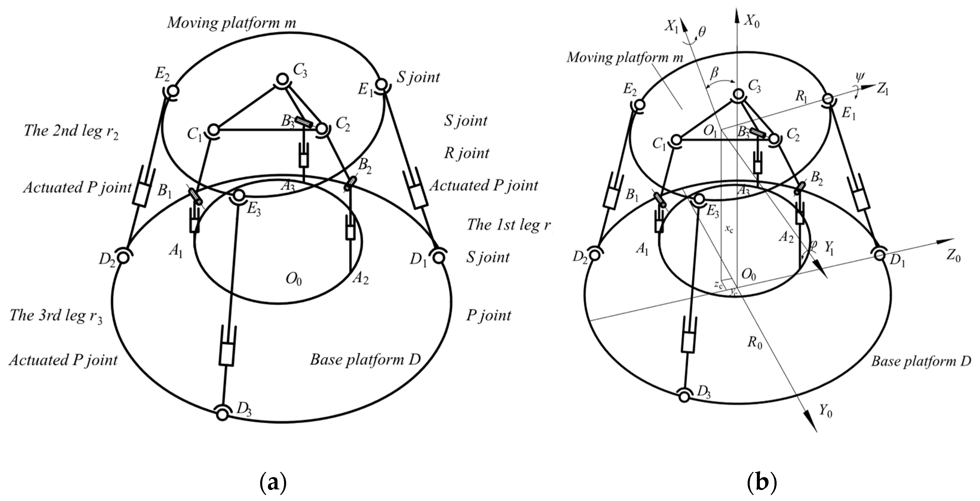
As shown in Figure 2a, the 3SPS + 3PRS PM includes a base platform D , a moving platform m, three SPS limbs r i   ( i = 1 ,   2 ,   3 ) , and three PRS limbs p i   ( i = 1 ,   2 ,   3 ) . The shape of the base platform D and the moving platform m is circular. In r i , the bottom of the prismatic joint P is attached to D by a S joint. Among them, the P joint of r i is the actuator of the PM. The other end of the P joint is also a spherical joint S fixed to m. In p i , the PRS limb consists of a prismatic joint P, a revolute joint R, and a spherical joint S from the base platform D to the moving platform m.
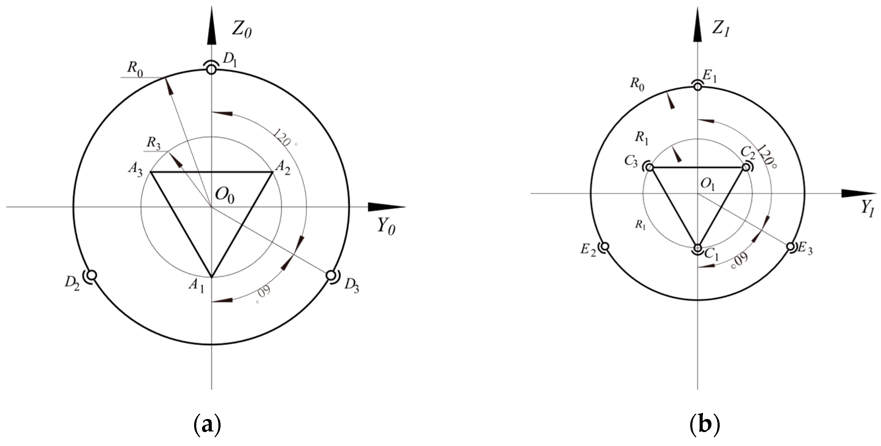
On the base platform, D , D 1 , D 2 and D 3 are separated by 120° on the circle with O 0 as a center point and R 0 as the radius. To simplify this expression, let O 0 - X 0 Y 0 Z 0 be the inertial frame. O 0 is the center of D . X 0 is perpendicular to the base platform D and points upward. Y 0 is parallel with D 2 D 3 , and Z 0 is parallel with O 0 D 1 , thereby forming a right-handed orthogonal frame O 0 - X 0 Y 0 Z 0 . On the moving platform m, E 1 , E 2 , and E 3 are separated by 120° on the circle with O 1 as center point and R 1 as radius. Let O 1 - X 1 Y 1 Z 1 be the moving frame. O 1 is the center of m. X 1 is normal to m and points upward. Y 1 is parallel with E 2 E 3 , and Z 1 is parallel with O 1 E 1 , thereby forming a right-handed orthogonal frame O 1 - X 1 Y 1 Z 1 , as shown in Figure 2b.
As shown in Figure 3a, on the base platform D , the points A i ( i = 1 ,   2 ,   3 ) , which connect the PRS limbs p i ( i = 1 ,   2 ,   3 ) and base platform D , are separated by 120° on the circle with R 3 as radius. The plane of the circle is parallel with the Y 0 Z 0 plane and the center is on the X 0 -axis. As shown in Figure 3b. On the moving platform m, the points C i ( i = 1 ,   2 ,   3 ) that connect the PRS limbs p i ( i = 1 ,   2 ,   3 ) and the moving platform m are separated by 120° on the circle with O 1 as the center and R 2 as the radius.

1.2. Calculation of the Degree of Freedom

The DOF of the 3SPS + 3PRS parallel manipulator can be calculated by the revised Grübler–Kutzbach equation [27], as shown below:
F = λ ( n j 1 ) + i = 1 j f i f p
where F is the DOF number of the PM, λ is the DOF number of the space, n is the number of links in the PM, j is the number of joints, f i is the DOF number of the i-th joint, and f p is the passive DOF. For the 3SPS + 3PRS PM, there are nine S joints, six P joints and three R joints. The application of (1) leads to:
F = λ ( n j 1 ) + i = 1 j f i f p = 6 × ( 14 18 1 ) + ( 9 × 1 + 9 × 3 ) 3 = 3

2. Kinematic Modeling of the 3SPS + 3PRS PM

2.1. Positional Posture Model

As shown in Figure 2, in the 3-DOF 3SPS + 3PRS PM, the 6-dimensional positional posture of the moving platform has a coupling relationship. To simplify the expression, ZYX-type Euler angles are adopted to describe the posture of the moving platform. Let θ , φ , and ψ be three Euler angles on the corresponding axes. Otherwise, let [ x c y c z c ] T be the position of the moving platform’s center.
Let C i m   ( i = 1 ,   2 ,   3 ) be the vector of C i in O 0 - X 0 Y 0 Z 0 , E i m   ( i = 1 ,   2 ,   3 ) be the vector of E i in O 0 - X 0 Y 0 Z 0 , A i   ( i = 1 ,   2 ,   3 ) be the vector of A i in O 0 - X 0 Y 0 Z 0 , and D i   ( i = 1 ,   2 ,   3 ) be the vector of D i   ( i = 1 , 2 , 3 ) in O 0 - X 0 Y 0 Z 0 . Based on the mechanism architecture, the expressions of C   m i , E   m i , A i and D i are shown in Appendix A.
Let R D m be the rotational transformation matrix from O 0 - X 0 Y 0 Z 0 to O 1 - X 1 Y 1 Z 1 and P be the vectors of O 1 in O 0 - X 0 Y 0 Z 0 . Then, C i   ( i = 1 ,   2 ,   3 ) and E i   ( i = 1 ,   2 ,   3 ) can be expressed as below:
C i = R D m C i m + P ( i = 1 , 2 , 3 ) E i = R D m E i m + P ( i = 1 , 2 , 3 )
R D m = [ l x m x n x l y m y n y l z m z n z ]               = [ c o s φ c o s ψ c o s φ s i n ψ s i n φ s i n θ s i n φ c o s ψ + c o s θ s i n ψ s i n θ s i n φ s i n ψ + c o s θ c o s ψ s i n θ c o s φ c o s θ s i n φ c o s ψ + s i n θ s i n ψ c o s θ s i n φ s i n ψ + s i n θ c o s ψ c o s θ c o s φ ]
P = [ x c y c z c ] T
According to the mechanism architecture of the 3SPS + 3PRS PM, C i   ( i = 1 ,   2 ,   3 ) is constrained in the plane O 0 A i B i . This leads to:
n y R 2 + y c = 0
3 m y R 2 4 n y R 2 4 y c 2 + 3 m z R 2 4 + 3 n z R 2 4 + 3 z c 2 = 0
3 m y R 2 4 n y R 2 4 y c 2 + 3 m z R 2 4 3 n z R 2 4 3 z c 2 = 0
From (6)–(8), the positional posture coupling relationships of m can be obtained.
y c = s i n θ c o s φ R 2
z c = 1 2 ( s i n θ s i n φ s i n ψ + c o s θ c o s ψ c o s θ c o s φ ) R 2
θ = a t a n ( s i n φ s i n ψ c o s φ + c o s ψ )
Equations (9)–(11) show that x c , φ , and ψ is the independent kinematic parameters of this PM.
For PMs, the inverse kinematics equation is easy to solve. Based on the mechanism architecture of PM and the closed-loop vector method, the inverse positional posture Equation 3SPS + 3PRS PM can be expressed as below:
l 1 2 = ( n x R 1 + x c ) 2 + ( n y R 1 + y c ) 2 + ( n z R 1 + z c R 0 ) 2
l 2 2 = 1 4 ( 3 m x R 1 - n x R 1 + 2 x c ) 2 + 1 4 ( 3 m y R 1 n y R 1 + 2 y c + 3 R 0 ) 2 + 1 4 ( 3 m z R 1 n z R 1 + 2 z c + R 0 ) 2
l 3 2 = 1 4 ( 3 m x R 1 n x R 1 + 2 x c ) 2 + 1 4 ( 3 m y R 1 n y R 1 + 2 y c 3 R 0 ) 2 + 1 4 ( 3 m z R 1 n z R 1 + 2 z c + R 0 ) 2
where l i   ( i = 1 ,   2 ,   3 ) denotes the lengths of the SPS limbs r i   ( i = 1 ,   2 ,   3 ) . From the above equations, l i   ( i = 1 ,   2 ,   3 ) can be solved with the positional posture parameters of the moving platform m.
Otherwise, for Equations (9)–(14), the forward positional posture equation is obtained:
F ( x μ ) = 0
where:
x = [ x c y c z c θ φ ψ ] T
μ = [ l 1 l 2 l 3 ] T
For the given lengths of the SPS limbs r i   ( i = 1 ,   2 ,   3 ) , the unknown positional posture parameters can be solved by using numerical methods.

2.2. Velocity Model

In order to analyze the relation between the velocities of the actuator and the velocities of the moving platform, it is necessary to establish a Jacobian matrix. As an effective mathematic tool, the screw theory, which can describe and solve problems more concisely, has been widely used in kinematics. Thus, this paper uses the screw theory to derive a complete Jacobian matrix. In order to obtain the reciprocal screws of the limbs, the vectors on the SPS limbs and PRS limbs were analyzed.
(1)
The SPS limbs
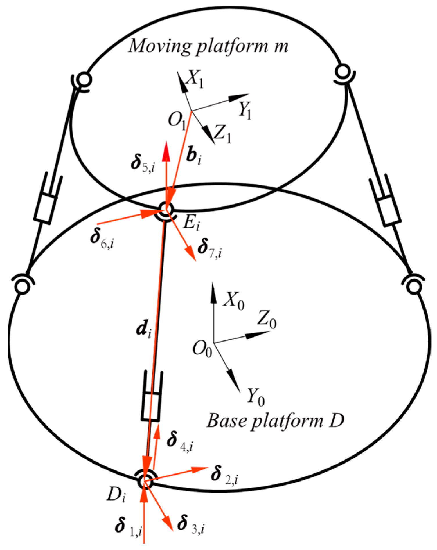
In order to analyze the SPS limbs r i   ( i = 1 ,   2 ,   3 ) and obtain the twist screws of the SPS limbs, let δ j , i be the unit vector on the SPS limbs. Based on the screw method and the mechanism architecture of the PM, for the S joint, there are three unit vectors through the center of sphere, which are respectively parallel with the X 0 -axis, Y 0 -axis, and Z 0 -axis, such as δ j , i   ( j = 1 ,   2 ,   3 ,   5 ,   6 ,   7 ) . For the P joint, let δ 4 , i be the unit vector from D i to E i . In addition, let b i be the vector from O 1 to E i and d i be the vector from E i to D i . As shown in Figure 4.
According to the mechanism architecture, each SPS limb consists of seven single-degree-of-freedom motion pairs, and each motion pair can be expressed as a twist screw. Only one of the three SPS limbs needs to be analyzed. The unit twist screws of all these motion pairs in r i can be obtained as follows:
S 1 , i = [ δ 1 , i ( b i + d i ) × δ 1 , i ] , S 2 , i = [ δ 2 , i ( b i + d i ) × δ 2 , i ] S 3 , i = [ δ 3 , i ( b i + d i ) × δ 3 , i ] , S 4 , i = [ 0 δ 4 , i ] S 5 , i = [ δ 5 , i b i × δ 5 , i ] , S 6 , i = [ δ 6 , i b i × δ 6 , i ] , S 7 , i i = [ δ 7 , i b i × δ 7 , i ]
The twist screw of r i can be expressed as:
S a = θ ˙ 1 , i S 1 , i + θ ˙ 2 , i S 3 , i + θ ˙ 3 , i S 3 , i + l ˙ i S 4 , i + θ ˙ 5 , i S 5 , i + θ ˙ 6 , i S 6 , i + θ ˙ 7 , i S 7 , i
where S a denotes the twist screw of r i :
S a = [ ω v ] T
Since the P joint in r i is actuated, the corresponding screw is denoted as an input twist screw. Then, we assume the input twist is temporarily locked, and the unit wrench S r , i , can be obtained:
S r , i = [ δ 4 , i b i × δ 4 , i ]
This leads to:
S r , i S a = l ˙ i
Let the velocity of the moving platform be   V   =   [ v ω ] T . From Equation (20), this leads to:
J a V = v r
where:
J a = [ δ 4 , 1 b 1 × δ 4 , 1 δ 4 , 2 b 2 × δ 4 , 2 δ 4 , 3 b 3 × δ 4 , 3 ] , v r = [ l ˙ 1 l ˙ 2 l ˙ 3 ]
(2)
The PRS limbs
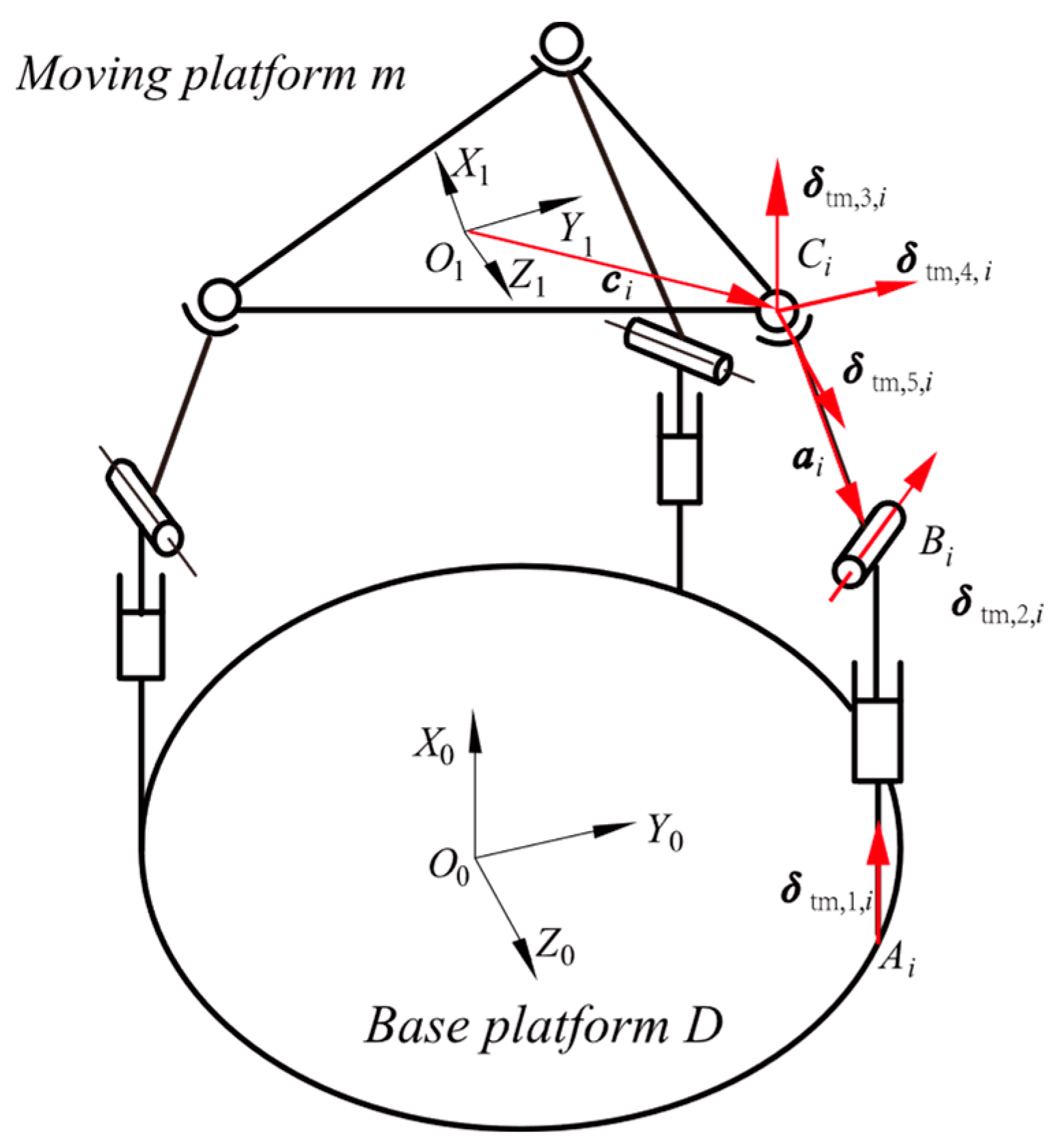
Similarly with the SPS limbs, as shown in Figure 5, the following unit vectors are used: δ t m , 1 , i , parallel with the X 0 -axis and through the point A i ; δ t m , 2 , i , parallel with the axis of the R joint and through the point B i ; δ t m , 3 , i , δ t m , 4 , i and δ t m , 5 , i , respectively parallel with the X 0 -axis, Z 0 -axis and Y 0 -axis and all through the point C i . In addition, c i is the vector from O 1 to C i , and a i is the vector from C i to B i .
According to the mechanism architecture, each PRS limb consists of five single-degree-of-freedom motion pairs, and each motion pair can be expressed as a twist screw. Only one of the three PRS limbs needs to be analyzed. The unit twist screws of all these motion pairs in p i can be obtained as follows:
S t m , 1 , i = [ 0 δ t m , 1 , i ] , S t m , 2 , i = [ δ t m , 2 , i ( c i + a i ) × δ t m , 2 , i ] S t m , 3 , i = [ δ t m , 3 , i c i × δ t m , 3 , i ] , S t m , 4 , i = [ δ t m , 4 , i c i × δ t m , 4 , i ] S t m , 5 , i = [ δ t m , 5 , i c i × δ t m , 5 , i ]
The twist screw of p i can be expressed as:
S b = l ˙ i S t m , 1 , i + θ ˙ t m , 2 , i S t m , 2 , i + θ ˙ t m , 3 , i S t m , 3 , i + θ ˙ t m , 4 , i S t m , 4 , i + θ ˙ t m , 5 , i S t m , 5 , i
where S b denotes the twist screw of p i .
The five twist screws are independent and thus have only one reciprocal screw, which is referred to as the constraint wrench screw:
S t m , r , i = [ n i c i × n i ]
where:
n 1 = [ 0 1 0 ] n 2 = [ 0 1 2 3 2 ] n 3 = [ 0 1 2 3 2 ]
This leads to:
S t m , r , i S b = 0 3 × 1
J b V = 0 3 × 1
where:
J b = [ n 1 c 1 × n 1 n 2 c 2 × n 2 n 3 c 3 × n 3 ]
By combining Equation (22) with Equation (28), the relation between the velocities of the actuators and the velocity of the moving platform can be expressed as:
l ˙ = J V
J = [ δ 4 , 1 b 1 × δ 4 , 1 δ 4 , 2 b 2 × δ 4 , 2 δ 4 , 3 b 3 × δ 4 , 3 n 1 c 1 × n 1 n 2 c 2 × n 2 n 3 c 3 × n 3 ]
where:
l ˙ = [ l ˙ 1 l ˙ 2 l ˙ 3 0 0 0 ] T
J 6 × 6 is the Jacobian matrix of 3SPS + 3PRS PM, which maps the relation between the velocities of the actuator and the velocities of the moving platform. The combination of (29) and (30) can create an inverse velocity model of the PM. When V is given, l ˙ can be obtained according to (29) and (30). The Jacobian matrix J 6 × 6 is invertible matrix when the positional posture parameters are in the range that the AVEN requires. Then, the forward velocity model can be obtained as follows:
V = J 1 l ˙

2.3. Acceleration Model

Let a r be the acceleration vector of actuators and A be the acceleration vector of m. Deriving time from both sides of (29), a r can be expressed as below:
[ a r 0 3 × 1 ] = J A + V T H 6 × 6 × 6 V
where:
A = [ a ε ] , H 6 × 6 × 6 = [ H a H b ]
H 6 × 6 × 6 is the Hessian matrix of the 3SPS + 3PRS PM. The Hessian matrix contains two sub-matrices: one is the traditional Hessian matrix of limited 3-DOF PMs (named H a ), and the other is the constraints Hessian matrix (named H b ). Correspondingly, Equation (33) can be expressed as the following two equations:
a r = J a A + V T H a V
0 3 × 1 = J b A + V T H b V
where:
H a = [ H a 1 H a 2 H a 3 ] , H b = [ H b 1 H b 2 H b 3 ]
In order to obtain the expressions of H a i   ( i = 1 ,   2 ,   3 ) and H b i   ( i = 1 ,   2 ,   3 ) , taking the derivative of the vectors is necessary. For the SPS limbs r i , the derivatives of the vectors are shown in Appendix B. This leads to:
[ δ 4 , i T · ( b i × δ 4 , i ) T · ] = [ v ω ] H a i
H a i = 1 r i [ δ 4 , i 2 δ 4 , i 2 b i b i δ 4 , i 2 r i b i δ 4 , i + b i δ 4 , i 2 b i ]
The derivatives of the vectors of the PRS limbs p i are shown in Appendix C. Similarly, the expression of H b i can be expressed as below:
[ n i T · ( c i × n i ) T · ] = [ v ω ] H b i
H b i = [ 0 0 0 c i n i ]
The combination of (33), (37) and (39) are the inverse acceleration model of the 3SPS + PRS PM. When V and A are given, a r can be obtained according to (33). From Equation (33), the forward acceleration model can be determined as follows:
A = J - 1 [ a r 0 3 × 1 ] J - 1 V T H 6 × 6 × 6 V

3. Stiffness Modeling of the 3SPS + 3PRS PM

3.1. Stiffness Model

Stiffness, which reflects the PMs’ ability to resist elastic deformation, is a very important performance model for evaluating a parallel manipulator. Gosselin [14] presented that the stiffness can be represented by a matrix (named the stiffness matrix), which can obtained using the kinematic equations and the principle of virtual work. In order to establish the stiffness matrix, the force of the 3SPS + 3PRS PM must be analyzed. Let the external workloads be simplified as a wrench F e x t applied onto the moving platform at point O 1 . f e x t is a central force, and m e x t is a central torque, which is shown as:
F e x t = [ f e x t m e x t ]
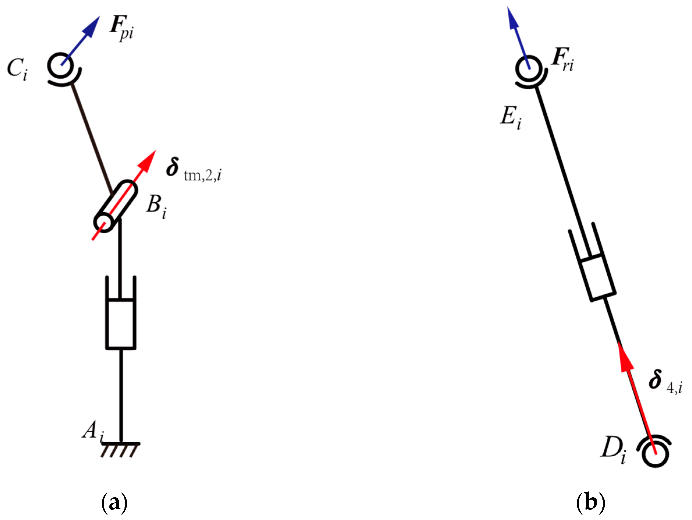
When ignoring the friction in all joints, the 3SPS + 3PRS PM is an ideal constrained system. As shown as Figure 6a. There are three constrained forces F pi ( i = 1 ,   2 ,   3 ) through the spherical joints of limbs p i . The unit vector f pi of the constrained forces F pi is parallel to the unit vector n i . Let F ri ( i = 1 ,   2 ,   3 ) be the active forces, which are applied on and along the active limb r i . The unit vector f ri of the constrained forces F ri is parallel to the unit vector δ 4 , i , as shown as Figure 6b.
In a static equilibrium state, using matrix representation, the static equilibrium equation can be derived as:
J T f = F e x t
where:
f = [ F r 1 F r 2 F r 3 F p 1 F p 2 F p 3 ] T
Let δ κ ri   ( i = 1 ,   2 ,   3 ) be the limb r i deformations along the forces F ri ; δ κ pi be the limbs p i ’s deformations along the forces F pi , and δ D be the deformations of the moving platform m. According to the principle of virtual work, the equation is obtained as follows:
f T δ κ + F e x t T δ D = 0
where:
δ κ = [ δ κ r 1 δ κ r 2 δ κ r 3 δ κ p 1 δ κ p 2 δ κ p 3 ] T
The derivation of the static equilibrium equation is shown in Appendix D.
According to (42) and (44), the following equation is obtained:
δ κ = J δ D
It is supposed that r i and p i are elastic and m and all joints have a rigid body. Let k d be the coefficient matrix mapping the relationships between the deformations and the forces that directly cause deformations.
f = k d δ κ
k d = [ k r 1 0 0 0 0 0 0 k r 2 0 0 0 0 0 0 k r 3 0 0 0 0 0 0 k p 1 0 0 0 0 0 0 k p 2 0 0 0 0 0 0 k p 3 ]
where k ri ( i = 1 , 2 , 3 ) are the coefficients mapping the relationships between δ κ r 1 and F ri , and k pi ( i = 1 , 2 , 3 ) are the coefficients mapping the relationships between δ κ pi and F pi . Let F r e a be the reaction force of the external force F e x t . Substituting (42) and (46) into (47) leads to:
F r e a = k p δ D
where:
k p = J T k d J
k p can also be expressed as:
k p = [ k t k t r k r t k r ] 6 × 6
where k t is a 3 × 3 translational stiffness matrix, and k r is a 3 × 3 rotational stiffness matrix.

3.2. Calculation of the Stiffness Coefficient

Ignoring the friction in the base platform, the moving platform, and all joints, the deformation of the limbs is analyzed. We can obtain the stiffness coefficient that maps the relationship between the deformations and the forces directly causing deformations.
(1)
The SPS limbs r i
F ri ( i = 1 , 2 , 3 ) are the active forces that are applied on and along the active limb r i . δ κ ri   ( i = 1 , 2 , 3 ) are the limb r i deformations along the force F ri . The coefficient mapping of the relationships between the deformations and the forces directly causing deformations can be expressed as follows:
f r i = k r i δ κ r i , k r i = E S r i r i
where E is the modular of elasticity and S ri is the area of r i .
(2)
The PRS limbs p i
F pi ( i = 1 , 2 , 3 ) are the active forces, which are applied on and along the limbs p i . δ κ pi   ( i = 1 ,   2 ,   3 ) are the limb p i deformations along the force F pi . The coefficient mapping the relationships between the deformations and the forces directly causing deformations can be expressed as follows:
f p i = k p i δ κ p i , k p i = 3 E I p i 2
where I is the moment inertia and E is the modular of elasticity.
From (49) to (52), the coefficient matrix that maps the relationships between the deformations and the forces directly causing deformations is obtained as follows:
k p = J T [ k r 1 0 0 0 0 0 0 k r 2 0 0 0 0 0 0 k r 3 0 0 0 0 0 0 k p 1 0 0 0 0 0 0 k p 2 0 0 0 0 0 0 k p 3 ] J

4. Numerical Examples

In order to verify the effectiveness of the kinematics model of the PM, a simulative model was built using the Simscape Multibody of Simulink. Then, we calculated the values of the kinematic parameters using the kinematic model and compared them with simulative results from the simulative model. For this exemplar PM, the dimension parameters are shown in Table 1. The simulative model of the PM is shown in Figure 7.

4.1. Positional Posture Numerical Example

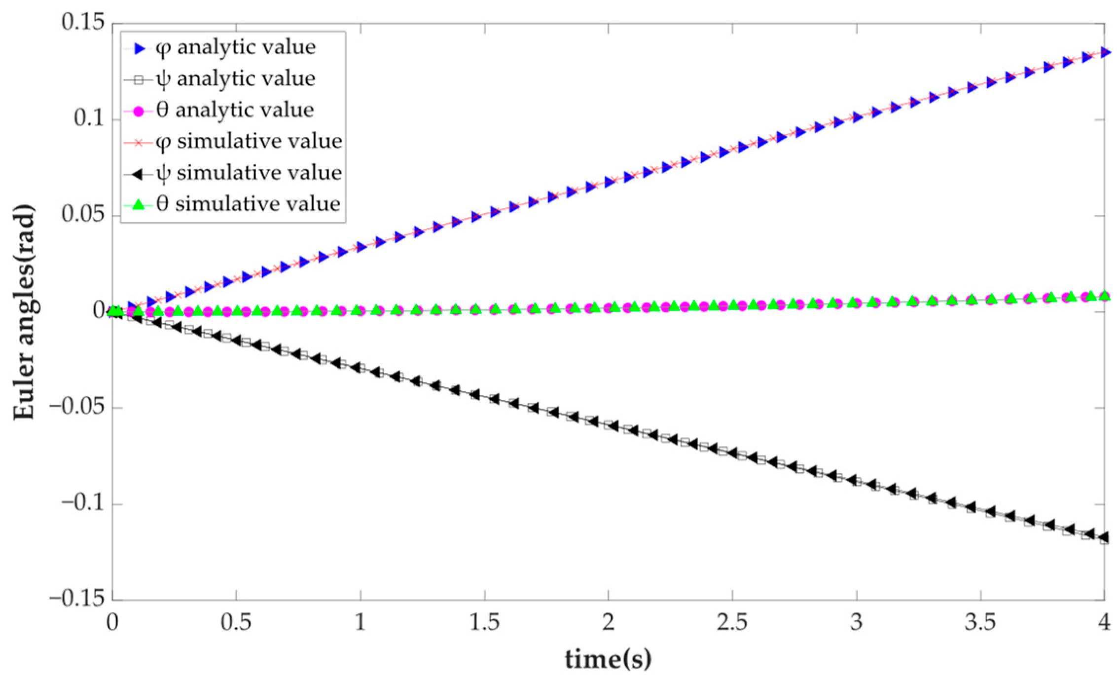
In the simulation, each actuator is given a constant velocity v i ( i = 1 , 2 , 3 ) and then the simulative results of the positional postures are obtained. Meanwhile, in the numerical calculation of (15), let the l i   ( i = 1 ,   2 ,   3 ) be the linear function of time t, for which the coefficient is v i . Then, we obtained the analytic results and compared them with the simulative results to verify the positional posture model. The curves of the posture parameters from the analysis and simulation are shown in Figure 8.
The curves of the positional parameters from the analysis and simulation are shown in Figure 9.
In addition, given the two groups of actuator lengths l i   ( i = 1 ,   2 ,   3 ) , we can obtain two groups of analytic results using the positional posture model. The comparison between analytic results and simulative results is shown in Table 2.
By comparing the curves in Figure 8 and Figure 9 and the values in Table 2, it is clear that the analytic values and the simulative values are in excellent agreement, which verifies the effectiveness of the positional posture model.

4.2. Kinematic Numerical Example

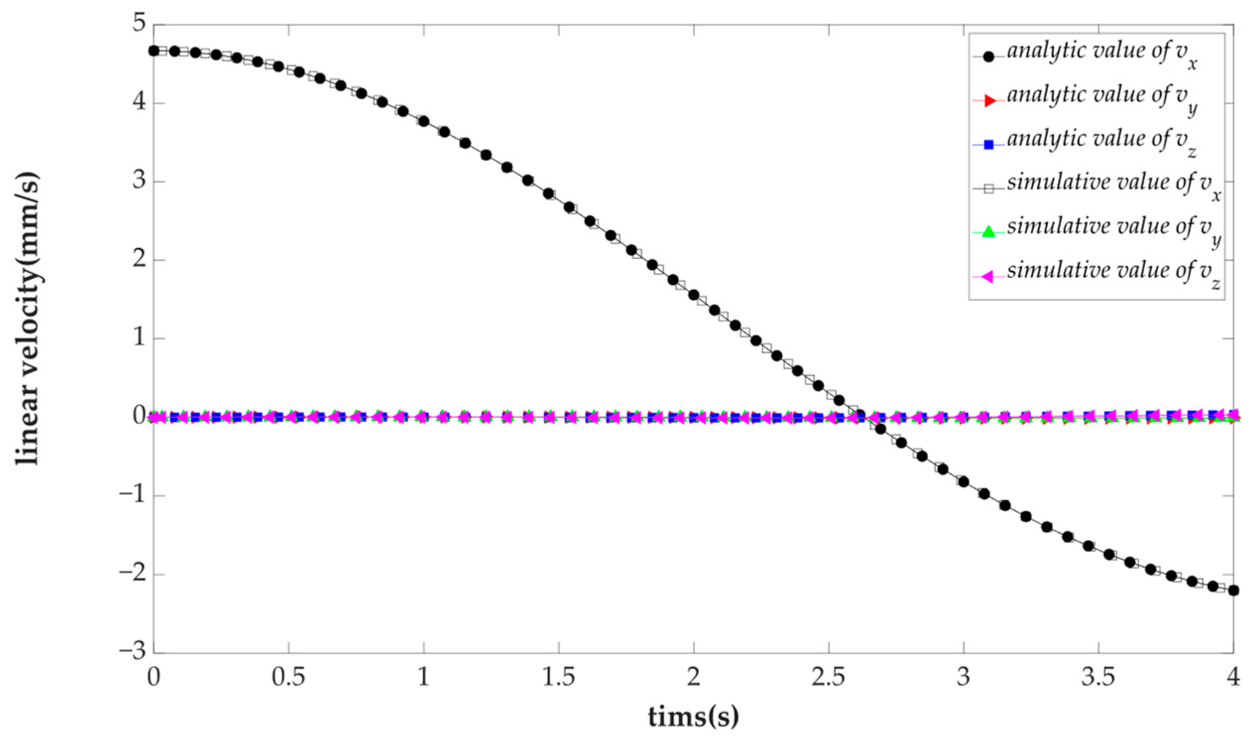
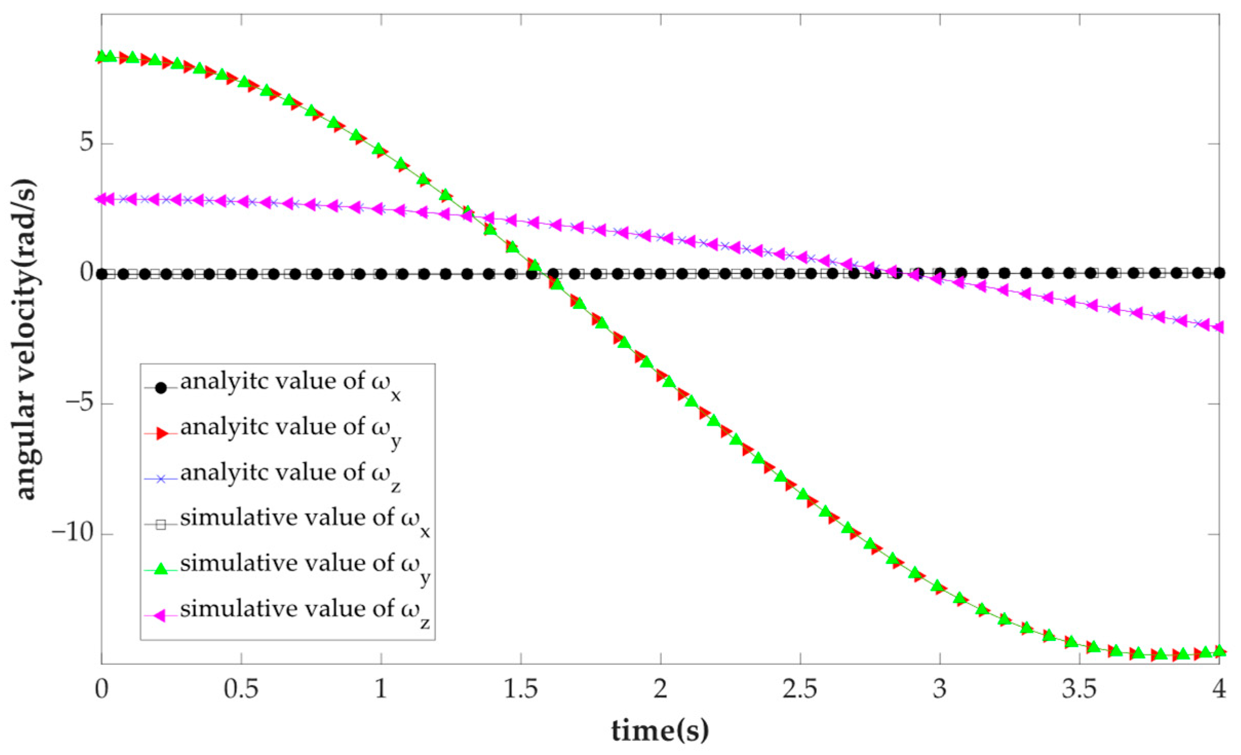
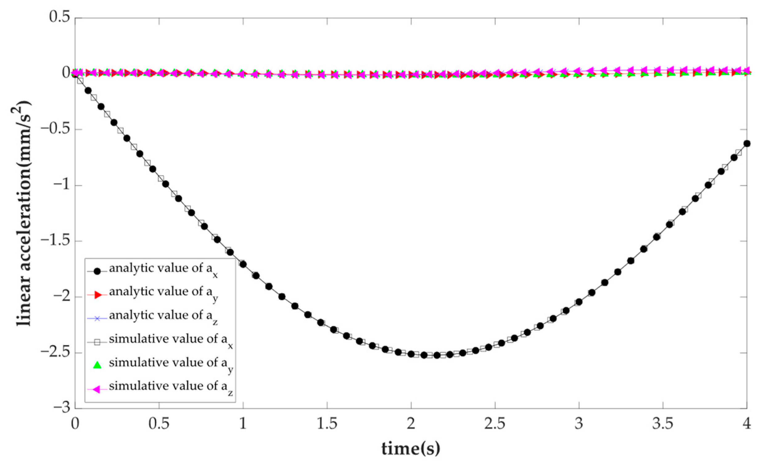
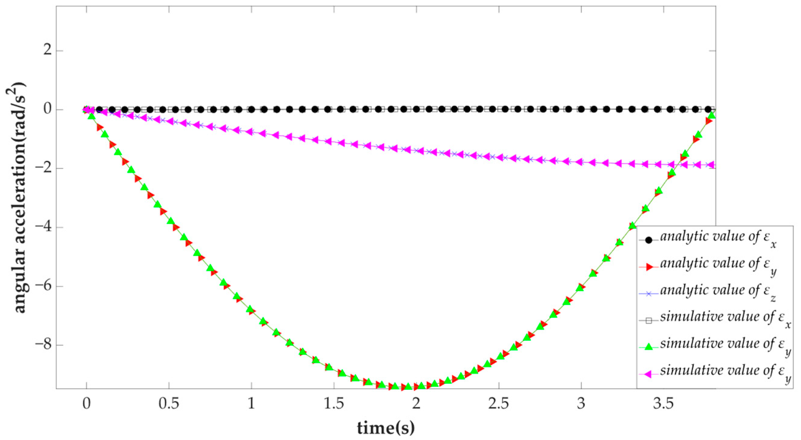
For this exemplar PM, let the actuator move according to the items shown in Table 3. In the analytic process, when the initial lengths of three SPS limbs and the velocities of the actuators are provided, the velocity v and ω of m can be calculated based on (30) and (32). Given the initial lengths of three SPS limbs, the velocities and the accelerations of the actuators, the acceleration a and ε of m can be calculated based on (40). In simulations, in the simulative PM, three simulation-driven modules are set for r i (i = 1, 2, 3), a velocity/acceleration sensor is set for m, and sensor values can be displayed by scope. Appling identical v r , a r calculated above the corresponding simulation-driven module, the comparison between analytic results and simulative results of linear velocity, angular velocity, linear acceleration and angular acceleration are respectively shown in Figure 10, Figure 11, Figure 12 and Figure 13.
The quantitative comparisons between the analytic values and the simulative values at t = 1s, t = 2s, and t = 3s are shown in Table 4.
From the results of the comparison, it is clear that the analytic and simulative values are in excellent agreement, which confirms accuracy of the kinematic model.

4.3. Workspace Analysis

The workspace of the PM is the space that the moving platform m can reach. For the exemplar, 3SPS + 3PRS PM, the connecting rods   B i C i are invariable, and the lengths of   A i B i are variable because of the P joint. Let l B C be the lengths of   B i C i ; z i be the lengths of   A i B i ; z min be the minimum lengths of   A i B i ; and z max be the maximum lengths of   A i B i . The limitation of the z i can be expressed as:
z min z i z max ( i = 1 , 2 , 3 )
Meanwhile, let λ i ( i = 1 , 2 , 3 ) be the rotation angle of the R joint, λ min be the minimum angles of λ i , and z max be the maximum angles of λ i . The limitation of λ i can be expressed as:
λ min λ i λ max ( i = 1 , 2 , 3 )
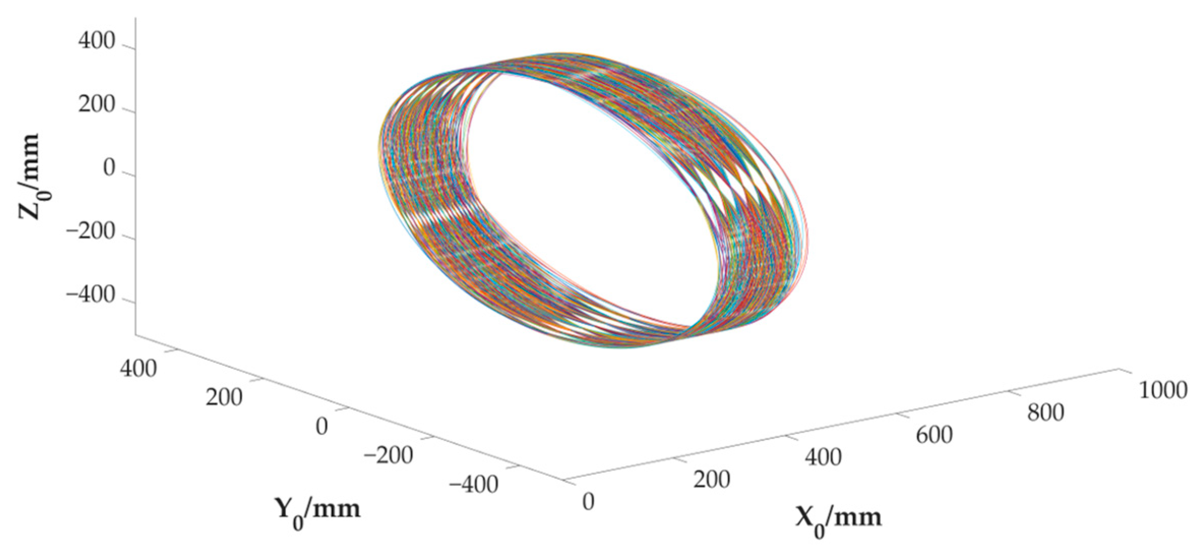
According to the forward positional posture model, given the lengths of the SPS limbs l i   ( i = 1 ,   2 ,   3 ) , with numerical method, the positional posture parameters of the moving platform m can be solved. In the process of solving the workspace, l i is provided within the limited range, and the forward positional posture equations are established. z i , λ i , and the positional posture parameters can be obtained by solving the equations. Judge whether z i and λ i are within the limited ranges. If they are in the range, obtain the coordinates of points on the m’s outer circle and plot the circle. If they are not in the range, continue to search. Figure 14, which illustrates the workspace, is shown below.
Otherwise, from (9) to (11), the offset between O 1 and the X 0 -axis is determined by φ and ψ . The relationship between them is shown in a. Let β be the angle between the X 1 -axis and X 0   axis. The relation between β , y c and z c is shown as Figure 15b.
The 3SPS + 3PRS PM has the approximate centering function, which can constrain the center of the moving platform in a certain space encircling the X 1 axis. Figure 15a shows that the offset value between O 1 and the axis through O 0 is less than 5 mm if angle φ [ 0.2 ,   0.2 ] rad or ψ [ 0.2 ,   0.2 ] rad. Figure 15b shows that the change value of displacement of O 1 in the X 0 or Y 0 direction is less than 3 mm if angle β   [ 0 ,   10 ] degree.

4.4. Stiffness Analysis

The minimum eigenvalue of the matrix k t is used to evaluate the translational stiffness. Similarly, the minimum eigenvalue of the matrix k r is used to evaluate the rotational stiffness. The minimum eigenvalues represent the minimum force required when the moving platform move the unit displacement at a certain positional posture state. The larger the minimum eigenvalue, the better the stiffness performance of the PM.
In order to study the effects of the positional posture parameters on stiffness performance, the stiffness values are calculated with the different input parameters given in Table 5.
The minimum eigenvalues of the translational and rotational stiffness matrix are solved, shown in Figure 16a,b.
According to Figure 16a, it can be seen that the translational stiffness value increases as x c decreases, and the maximum translation stiffness values are at points 1, 2 and 3. If the moving platform only rotates around the medians of the triangle E 1 E 2 E 3 , the translational stiffness is better than other positions. Figure 16b shows that the rotational stiffness mainly affected by the Euler angles φ ,   ψ , and the effect of the x c on rotational stiffness performance, is minimal.

5. Conclusions

This paper builds the kinematic model and the stiffness model of the 3SPS + 3PRS PM, which is used as the driving mechanism of axisymmetric vectoring exhaust nozzle (AVEN).
The complete kinematic models of the 3SPS + 3PRS PM are built, including the positional posture model, velocity model and acceleration model. According to the closed-loop vector method, the positional posture model is built. Using the screw theory, the Jacobian matrix is derived for building the velocity model. Through taking the derivative of the velocity model, the Hessian matrix is obtained to create the acceleration model. To compare the simulative results with the analytic results, the simulative model is built using the Simscape Multibody in Simulink, which shows the effectiveness of the kinematic model.
The workspace of the 3SPS + 3PRS PM is obtained using the forward positional posture model. Additionally, the offset between the O 1 - and X 0 -axes is quantificationally analyzed. The results show that the offset is less than 5 mm when φ or ψ is less than 10°, which reveals the centering function of the PM.
Based on Jacobian matrix and the principle of virtual work, the stiffness model is built, and thus the stiffness matrix is derived. The translational and rotational stiffness are analyzed using the minimum eigenvalues of the stiffness matrix as the evaluation indicators. The results show that the translational stiffness increases with the decrease in x c . And it is better than other postures if the moving platform only rotates around the medians of the triangle E 1 E 2 E 3 . The rotational stiffness is mainly determined by the posture parameters.
This study is expected to offer ideas for the kinematic and stiffness modeling of 3-DOF PM. The results of workspace and stiffness analysis could provide references for future application and optimizing of the AVEN’s driving mechanism.

Author Contributions

Conceptualization, S.Z.; methodology, S.Z.; software, H.G. and Z.J.; validation, H.G.; formal analysis, H.G.; resources, S.Z. and C.X; data curation, H.G.; writing—original draft preparation, H.G.; writing—review and editing, S.Z. and J.L.; visualization, H.G.; supervision, Z.L. and Q.H.; project administration, Z.L.; funding acquisition, C.X. All authors have read and agreed to the published version of the manuscript.

Funding

This research was funded by the National Science and Technology Major Project, grant number J2019-IV-0002-0069.

Institutional Review Board Statement

Not applicable.

Data Availability Statement

Not applicable.

Conflicts of Interest

The authors declare no conflict of interest.

Appendix A

C   m i , E   m i   , A i and D i   ( i = 1 ,   2 ,   3 ) can be expressed as below:
C 1 m = [ 0 0 R 2 ] , C 2 m = 1 2 [ 0 3 R 2 R 2 ] , C 3 m = 1 2 [ 0 3 R 2 R 2 ]
E 1 m = [ 0 0 R 1 ] , E 2 m = 1 2 [ 0 3 R 1 R 1 ] , E 3 m = 1 2 [ 0 3 R 1 R 1 ]
A 1 = [ x A 0 R 3 ] , A 2 = 1 2 [ x A 3 R 3 R 3 ] , A 3 = 1 2 [ x A 3 R 3 R 3 ]
D 1 = [ 0 0 R 0 ] , D 2 = 1 2 [ 0 3 R 0 R 0 ] , D 3 = 1 2 [ 0 3 R 0 R 0 ]

Appendix B

For the SPS limbs r i , the derivative of the vectors can be expressed as:
δ 4 , i T · = ( r i r i ) T · = 1 r i V T [ δ 4 , i 2 b i δ 4 , i 2 ]
b i T · = ω T b i
( b i × δ 4 , i ) T · = ( b ˙ i × δ 4 , i + b i × δ ˙ 4 , i ) T = 1 r i V T [ δ 4 , i 2 b i r i b i δ 4 , i + b i δ 4 , i 2 b i ]
where b i ^ is the matrix of the cross product of b i , and it is same with other vectors, for ex ample:
b i = [ b x b y b z ] , b i = [ 0 b z b y b z 0 b x b y b x 0 ]

Appendix C

For the PRS limbs r i , the derivative of the vectors can be expressed as:
n ˙ i T = [ 0 0 0 ]
c i T · = ω T c i
( c i × n i ) T · = ( c ˙ i × n i + c i × n ˙ i ) T = V T [ 0 c i n i ]

Appendix D

The derivation of the static equilibrium equation is shown as below:
F pi can be written as:
F p 1 = F p 1 n 1 , F p 2 = F p 2 n 2 , F p 3 = F p 3 n 3
F ri can be written as:
F r 1 = F r 1 δ 4 , i , F p 2 = F p 2 δ 4 , i , F p 3 = F p 3 δ 4 , i
In a static equilibrium state, the resultant force is 0, and the resultant force moment relative to point O 1 is also 0. Thus, the static equilibrium equations are expressed as:
F r 1 + F r 2 + F r 3 + F p 1 + F p 2 + F p 3 + f e x t = 0 3 × 1 b 1 × F r 1 + b 2 × F r 2 + b 3 × F r 3 + e 1 × F p 1 + e 2 × F p 2 + e 3 × F p 3 + m e x t = 0 3 × 1
From (62)–(64), using matrix representation, the static equilibrium equation can be derived as:
J T f = F e x t
where:
f = [ F r 1 F r 2 F r 3 F p 1 F p 2 F p 3 ] T

References

  1. Dastjerdi, A.H.; Sheikhi, M.M.; Masouleh, M.T. A complete analytical solution for the dimensional synthesis of 3-DOF delta parallel robot for a prescribed workspace. Mech. Mach. Theory 2020, 153, 103991. [Google Scholar] [CrossRef]
  2. Wang, L.; Xu, H.; Guan, L.; Zhi, Y. A novel 3-PUU parallel mechanism and its kinematic issues. Robot. Comput.-Integr. Manuf. 2016, 42, 86–102. [Google Scholar]
  3. Wang, L.; Xu, H.; Guan, L. Optimal design of a 3-PUU parallel mechanism with 2R1T DOFs. Robot. Mech. Mach. Theory 2017, 114, 190–203. [Google Scholar] [CrossRef]
  4. Ruiz-Hidalgo, N.C.; Blanco-Ortega, A.; Abúndez-Pliego, A.; Colín-Ocampo, J.; Arias-Montiel, M. Design and Control of a Novel 3-DOF Parallel Robot. In Proceedings of the IEEE International Conference on Mechatronics, Electronics and Automotive Engineering (ICMEAE), Cuernavaca, Mexico, 22–25 November 2016; pp. 66–71. [Google Scholar]
  5. Zou, Q.; Zhang, D.; Zhang, S.; Luo, X. Kinematic and dynamic analysis of a 3-DOF parallel mechanism. Int. J. Mech. Mater. Des. 2021, 17, 587–599. [Google Scholar] [CrossRef]
  6. Xu, Y.; Li, B.; Zhao, X. Influence upon Kinematics Performance of a Family of 3-PRS Parallel Mechanisms Affected by Kinematic Chain Layout. In Proceedings of the International Conference on Mechatronics and Industrial Informatics (ICMII), Guangzhou, China, 13–14 March 2013; pp. 37–41. [Google Scholar]
  7. Hu, X.; Li, F.; Tang, G. Kinematics Analysis of 3UPU_UP Coupling Parallel Platform in the Marine Environment. IEEE Access. 2020, 8, 158142–158151. [Google Scholar] [CrossRef]
  8. Hu, B.; Huang, Z. Kinetostatic model of overconstrained lower mobility parallel manipulators. Nonlinear Dyn. 2016, 8, 309–322. [Google Scholar] [CrossRef]
  9. Qin, Y.; Shirinzadeh, B.; Zhang, D.; Tian, Y. Design and kinematics modeling of a novel 3-DOF monolithic manipulator featuring improved Scott-Russell mechanisms. J. Mech. Des. 2013, 135, 101004. [Google Scholar] [CrossRef]
  10. Gallardo-Alvarado, J.; Rodriguez-Castro, R. A new parallel manipulator with multiple operation modes. J. Mech. Robot. 2018, 10, 051012. [Google Scholar] [CrossRef]
  11. Aghajari, M.; Fathollahi Dehkordi, S.; Korayem, M.H. Nonlinear dynamic analysis of the extended telescopic joints manipulator with flexible links. Arab. J. Sci. Eng. 2021, 46, 7909–7928. [Google Scholar] [CrossRef]
  12. Korayem, M.H.; Dehkordi, S.F.; Mojarradi, M.; Monfared, P. Analytical and experimental investigation of the dynamic behavior of a revolute-prismatic manipulator with N flexible links and hubs. Int. J. Adv. Manuf. Technol. 2019, 103, 2235–2256. [Google Scholar] [CrossRef]
  13. Korayem, M.H.; Shafei, A.M. Motion equation of nonholonomic wheeled mobile robotic manipulator with revolute–prismatic joints using recursive Gibbs–Appell formulation. Appl. Math. Model. 2015, 39, 1701–1716. [Google Scholar] [CrossRef]
  14. Gosselin, C. Stiffness mapping for parallel manipulators. IEEE Trans. Robot. Autom. 1990, 6, 377–382. [Google Scholar] [CrossRef]
  15. Gonçalves, R.S.; Carvalho, J.C.M. Stiffness Analysis of Parallel Manipulator Using Matrix Structural Analysis. In Proceedings of the 2nd European Conference on Mechanism Science, Cassino, Italy, 17–20 September 2008; pp. 255–262. [Google Scholar]
  16. Lu, Y.; Hu, B.; Yu, J. Analyses of the stiffness and elastic deformation of a 2 (3-SPR) serial—Parallel manipulator. Proc. Inst. Mech. Eng. Part K J. Multi-body Dyn. 2009, 223, 189–198. [Google Scholar] [CrossRef]
  17. Shankar Ganesh, S.; Koteswara Rao, A.B. Stiffness of a 3-degree of freedom translational parallel kinematic machine. Front. Mech. Eng. 2014, 9, 233–241. [Google Scholar] [CrossRef]
  18. Zhang, N. Stiffness Analysis of a 3-DOF 2SPR+RPS Parallel Manipulator. In Proceedings of the 11th International Conference on Intelligent Human-Machine Systems and Cybernetics (IHMSC), Hangzhou, China, 24–25 August 2019; pp. 76–79. [Google Scholar]
  19. Ceccarelli, M.; Carbone, G.A. Stiffness analysis for CaPaMan (Cassino parallel manipulator). Mech. Mach. Theory 2002, 37, 427–439. [Google Scholar] [CrossRef]
  20. Ye, N.; Hu, B. Kinematic and Stiffness Modeling of a Novel 3-DOF RPU+UPU+SPU Parallel Manipulator. IEEE Access 2022, 10, 6304–6318. [Google Scholar] [CrossRef]
  21. Zeng, Q.; Ehmann, K.F.; Cao, J. Tri-pyramid Robot: Stiffness modeling of a 3-DOF translational parallel manipulator. Robotica 2016, 34, 383–402. [Google Scholar] [CrossRef]
  22. Rezaei, A.; Akbarzadeh, A. Position and stiffness analysis of a new asymmetric 2 PRR–PPR parallel CNC machine. Adv. Robot. 2013, 27, 133–145. [Google Scholar] [CrossRef]
  23. Wu, J.; Li, T.; Wang, J.; Wang, L. Stiffness and natural frequency of a 3-DOF parallel manipulator with consideration of additional leg candidates. Robot. Auton. Syst. 2013, 61, 868–875. [Google Scholar] [CrossRef]
  24. Yu, G.; Wang, L.; Wu, J.; Wang, D.; Hu, C. Stiffness modeling approach for a 3-DOF parallel manipulator with consideration of nonlinear joint stiffness. Mech. Mach. Theory 2018, 123, 137–152. [Google Scholar] [CrossRef]
  25. Wu, G. Stiffness analysis and optimization of a co-axial spherical parallel manipulator. Model. Identif. Control 2014, 35, 21–30. [Google Scholar] [CrossRef] [Green Version]
  26. Zhang, H.; Tang, J.; Yan, C.; Cui, G.; Zhang, M.; Yao, Y.A. Stiffness analysis of a 3-DOF parallel mechanism for engineering special machining. Mech. Sci. 2022, 13, 635–645. [Google Scholar] [CrossRef]
  27. Merlet, J.P. Parallel Robots; Springer Science & Business Media: London, UK, 2005; pp. 25–30. [Google Scholar]
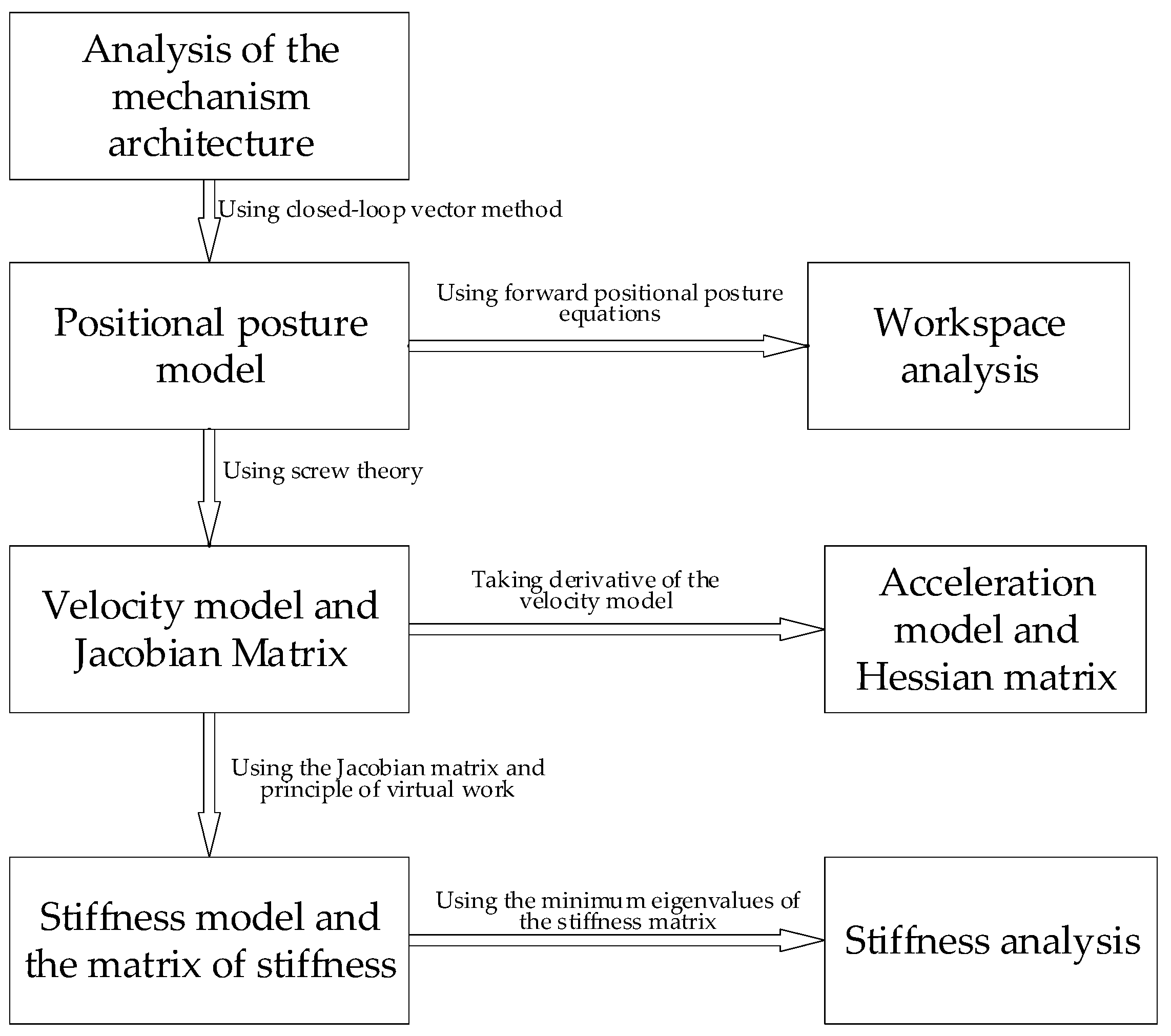
Figure 1. The flowchart of the main content.
Mathematics 10 04465 g001
Figure 2. (a) The mechanism architecture of the 3SPS + 3PRS PM; (b) Frames of reference.
Mathematics 10 04465 g002
Figure 3. (a) The inertial frame on the base platform D; (b) The moving frame on the moving platform m.
Mathematics 10 04465 g003
Figure 4. The vector representation of the SPS limbs.
Mathematics 10 04465 g004
Figure 5. The vector representation of the PRS limbs.
Mathematics 10 04465 g005
Figure 6. (a) The constrained force on the PRS limb; (b) The active force on the SPS limb.
Mathematics 10 04465 g006
Figure 7. The simulative model for this example PM.
Mathematics 10 04465 g007
Figure 8. The comparison between analytic results and simulative results of posture parameters of m.
Mathematics 10 04465 g008
Figure 9. The comparison between analytic results and simulative results of positional parameters of m.
Mathematics 10 04465 g009
Figure 10. The comparison between analytic results and simulative results of linear velocity of m.
Mathematics 10 04465 g010
Figure 11. The comparison between analytic results and simulative results of angular velocity of m.
Mathematics 10 04465 g011
Figure 12. The comparison between analytic results and simulative results of linear acceleration of m.
Mathematics 10 04465 g012
Figure 13. The comparison between analytic results and simulative results of angular acceleration of m.
Mathematics 10 04465 g013
Figure 14. The workspace of the 3SPS + 3PRS PM.
Mathematics 10 04465 g014
Figure 15. (a) The offset between the O 1 - and X 0 -axes; (b) The relation between β , y c and z c .
Mathematics 10 04465 g015
Figure 16. (a) The translational stiffness of the PM; (b) The rotational stiffness of the PM.
Mathematics 10 04465 g016
Table 1. The dimension parameters of the PM.
R 0 (mm) R 1 (mm) R 2 (mm) R 3 (mm)
470400300350
Table 2. The comparison of simulative and analytic values of positional posture parameters.
No.Initial (mm)ParametersAnalytic Value (mm)Simulative Value (mm)ParametersAnalytic Value (mm)Simulative Value (mm)
1 l 1 40   x c 390.5390.5 θ 0.00020.0002
l 2 30   y c 0.03730.0373 φ 0.02540.0254
l 3 20   z c 0.02140.0294 ψ 0.01470.0147
2 l 1 100   x c 461.4046461.1046 θ 00
l 2 120   y c 0.00050.0004 φ 00
l 3 80   z c 0.17070.1951 ψ 0.05840.0584
Table 3. The initial parameters of 3 actuators and their acceleration.
InitialAcceleration
l 1 (mm) l 2 (mm) l 3 (mm) a r 1 (mm/ s 2 ) a r 2 (mm/ s 2 ) a r 3 (mm/ s 2 )
366.7424366.7424366.7424 5 π 2 8 sin ( π t 4 ) 5 π 2 32 sin ( π t 8 ) 5 π 2 128 sin ( π t 16 )
Table 4. The comparison of simulative and analytic values of kinematic parameters.
Kinematict = 1st = 2st = 3s
ParametersAnalyticSimulativeAnalyticSimulativeAnalyticSimulative
v x   ( mm / s ) 3.76833.8351.55891.659−0.8208−0.7382
v y   ( mm / s ) 0.00460.0047−0.0011−0.0008−0.0049−0.0096
v z   ( mm / s ) 0.00400.0040−0.0055−0.00510.00120.0011
ω x   ( rad / s ) 000000
ω y   ( rad / s ) 0.00470.0049−0.0039−0.0035−0.0121−0.0118
ω z   ( rad / s ) 0.00250.00250.00140.001400
a x   ( mm / s 2 ) −1.7067−1.593−2.5107−2.491−2.0427−2.214
a y   ( mm / s 2 ) 0000−0.0040−0.0047
a z   ( mm / s 2 ) −0.0046−0.0039−0.0079−0.00830.02380.0230
ε x   ( rad / s 2 ) 000000
ε y   ( rad / s 2 ) −0.0068−0.0064−0.0094−0.0094−0.0060−0.0064
ε z   ( rad / s 2 ) 00.0001−0.0014−0.0013−0.0018−0.0018
Table 5. The positional posture parameters.
x c   ( mm ) φ (rad) ψ (rad)
400, 480, 560[− π 18 , π 18 ][− π 18 , π 18 ]
Publisher’s Note: MDPI stays neutral with regard to jurisdictional claims in published maps and institutional affiliations.