Article

Theoretical Study of the Static and Dynamic Characteristics of a Slotted Adaptive Hydrostatic Thrust Bearing with a Regulator of the Lubricant Output Flow

Polytechnic Institute, Siberian Federal University, 660079 Krasnoyarsk, Russia
*
Author to whom correspondence should be addressed.
Mathematics 2022, 10(3), 355; https://doi.org/10.3390/math10030355
Submission received: 6 January 2022 / Revised: 19 January 2022 / Accepted: 23 January 2022 / Published: 24 January 2022

Abstract

:
This manuscript considers the design of a slotted adaptive hydrostatic thrust bearing with a regulator of the lubricant output flow. A theoretical study of its static and dynamic characteristics was carried out. The aim of the study was to test the reliability of the hypothesis concerning the possibility of obtaining a stable-to-oscillation adaptive thrust bearing of negative compliance, avoiding the need for a complex system of external combined throttling by replacing it with a simple slotted throttle. Mathematical modeling of the thrust bearing movement was carried out. The possibility of reducing the compliance to negative values is shown, providing the bearing with an adaptive function, consisting of using the structure as a bearing and as an active deformation compensator of the elastic system of a metal-cutting machine in order to improve the quality of the metalwork. Analysis of load static characteristics showed that negative compliance is provided over a wide range of loads, which can be up to 75% or more of the range of permissible bearing loads. Based on the study of dynamic characteristics, it was concluded that with a targeted selection of parameters that have a major effect on the dynamics of the structure, the considered adaptive hydrostatic thrust bearing can attain a very high quality of dynamics. It is shown that the viscous damping of the lubricating film enclosed in the gaps and the damping of the material of the elastic ring of the regulator are important resources for ensuring the optimal dynamics of the thrust bearing.

1. Introduction

Sliding bearings with hydrostatic lubrication (journal bearings, thrust bearings, and guides) used in modern metal-cutting machines usually work as passive supporting structures [1,2]. At the same time, these devices can act as adaptive units, which, in addition to their load-carrying function, are capable of performing the role of automatic deformation compensators of the technological system of the machine, thereby helping to reduce errors and, consequently, reduce the time of metalworking [3,4]. The adaptive function of such bearings arises only in those designs that are able to compensate for the positive compliance of the technological system of the machine, operating in the modes of negative compliance and thereby providing the total zero compliance of the machine [5,6]. In the latter cases, the direction of the reaction vector of the lubricating film under pressure is opposite to that of the cutting force.
The compliance of conventional hydrostatic bearings is always positive [7,8]. To reduce this, special devices are used; these are lubricant flow regulators or displacement compensators [9,10,11,12].
In hydrostatic and gas-static bearings with flow regulators, which are usually installed at the inlet of the lubricating flow, compliance reduction is obtained with the automatic supply of an additional volume of lubricant, which contributes to an additional increase in pressure in the bearing gap and, consequently, the desired compliance mode being achieved [13,14]. Studies have shown that the inflow of additional energy contributes to a significant deterioration in the dynamic quality of the structure up to the loss of stability [15,16]. It is possible to improve the dynamics of the bearings due to the complication of the design through the use of an external combined throttling system (ECTS) whereby an additional hydraulic resistance is installed between the bearing gap and the regulator, which makes it possible to put in place an inter-throttle chamber, the volume of lubrication of which acts as a viscous damper for energy dissipation [17,18].
Bearings with displacement compensators are divided into two types: those with full compensation and those with partial compensation [19,20]. In contrast to bearings with active compensation of the flow rate, passive throttles are installed at the inlet of the ECTS, which provides better dynamics for structures [11]. However, even such bearings with negative compliance have low dynamics; therefore, the ECTS is also used in these. In the first, the displacement compensator is installed between the input passive throttle and the bearing gap, which are separated by an intermediate throttle of low resistance and the ECTS chamber [21]. A decrease in compliance in such structures is achieved by adding the positive compliance of the bearing gap and the negative compliance of the compensator. Partial displacement compensation is the result of a combination of a displacement compensator and a lubricant output flow regulator (LOFR) [10,22]. The improvement in the dynamics of such structures is provided by the use of an ECTS.
In work [4], it is shown that the stability of a step hydrostatic thrust bearing with an LOFR can be provided without the use of an ECTS, which simplifies the design. The mathematical model of the bearing takes into account the compliance of the elastic displacement compensator, but what is not taken into account is that, at the same time, it can act as a damper, which improves the dynamics of the bearing.
In this paper, we consider the design of a slotted hydrostatic thrust bearing with an LOFR and study its static and dynamic characteristics, taking into account the compliance and damping of the regulator. Figure 1 shows a diagram of a slotted adaptive hydrostatic thrust bearing with LOFR.
The structure contains a shaft, 1, and a base, 2, to which a rigid ring, 4, of an inner radius r1 and an outer radius r0 is hermetically connected by means of an elastic ring, 3, of an inner radius r2. The thrust bearing is powered by a lubricant injection source supplied to the slotted throttle, 5, under pressure ps. In working conditions, a lubricating gap of thickness h is created between the surfaces of ring 4 and shaft 1. Between base 2 and ring 4 there is a blind annular gap of thickness ht, at the entrance to which the lubricant is under pressure pt < ps, formed as a result of overcoming the hydraulic resistance to the lubricant flow in slotted throttle 5. In the operating state, with increasing load f on the thrust bearing, the gap h decreases and its hydraulic resistance increases, as a result of which the pressure pt increases. In this case, the force reactions wt and we of the lubricant film (which is under pressure in the gaps ht and h) both increase. At wt > we, under the action of a force equal to the difference between these reactions, the axial deformation e of elastic ring 3 increases, limiting the gap h, again increasing its hydraulic resistance and pressure pt, which brings about a decrease in the compliance of the thrust bearing
k = h s f ,
where
h s = h + e
is the thickness of the lubricating gap enclosed between the working surfaces of base 2 and shaft 1, e is the deformation of ring 3. The force wtwe is balanced by the force of resistance to deformation of ring 3. By varying the size of the elastic ring and its axial compliance ke, it is possible to reduce the compliance of the thrust bearing k to negative values.
The paper considers a mathematical model of the unsteady state of the thrust bearing; static and dynamic characteristics of the bearing are calculated and studied.

2. Mathematical Modeling

When studying the characteristics of the thrust bearing, we take a plane-parallel movement model of the working surfaces of the moving elements in which the thickness of the lubricant layer in the gaps does not depend on the radius. In addition, we assume that the loaded thrust bearing has reached a steady-state temperature regime at which the dynamic viscosity of the lubricant is constant.
It is convenient to study the characteristics of the thrust bearing in a dimensionless form. This allows us to significantly reduce the number of variable parameters that affect the characteristics of the thrust bearing. Following [4], we take the scales of values: ps for pressures, r0 for radii, t0 for the current time, h0 for gaps and deformation e, π h 0 3 p s 6 μ for volumetric lubricant flow rate, 2 π r 0 2 p s for axial forces, where h0 corresponds to the gap h in the bearing that carries the design load f0, and μ is the lubricant viscosity. Dimensionless quantities are signified by Greek and capital Latin letters.
The reactions of pressure forces in mentioned areas are determined by the general formula [4]
W i = R i , 1 R i , 2 R P d R ,
where P(R,τ) is a function of the pressure in the clearances of the thrust bearing.
The formula for the lubricant flow rate at the inlet and outlet of the corresponding gaps has the form [4]
Q i = H i 3 lim R R 1 ( R d P d R ) .
The pressure function satisfies the unsteady Reynolds equation for an incompressible fluid [22]
R ( R H i 3 P R ) = σ R H ˙ i ,
where Hi(τ) is the function of the gap, R is the current radius, σ = 12 μ r 0 2 h 0 2 p s t 0 is the so-called “compression number” of the film of the liquid in the gap, and τ is the dimensionless time.
On a circle, the R [ 0 , R 1 ] boundary conditions for the pressure function are of the form
P R ( 0 , τ ) = 0 , P ( R 1 , τ ) = P t ( τ ) .
On the ring R [ R 1 , 1 ] in the gap H region, the boundary value problem for Equation (5) satisfies the boundary conditions
P ( R 1 , τ ) = P t ( τ ) , P ( 1 , τ ) = 0 .
For the blind gap region, the boundary conditions for the boundary value problem with Equation (5) are
P ( R 1 , τ ) = P t ( τ ) , P R ( R 2 , τ ) = 0 .
The solution of the boundary value problem (5), (6) is the function
P ( R , τ ) = P t + σ H ˙ s 4 H s 3 ( R 2 R 1 2 ) .
On the ring in the region of the gap H, for the boundary value problem (5), (7) has the solution
P ( R , τ ) = P t ln R ln R 1 + σ H ˙ 4 H 3 [ R 2 + ( 1 R 1 2 ) ln R ln R 1 1 ] .
On the ring R [ R 1 , R 2 ] , in the region of the blind gap Ht, the solution to the boundary value problem (5), (8) is the function
P ( R , τ ) = P t + σ H ˙ t 4 H t 3 ( R 2 R 1 2 2 R 2 2 ln R R 1 ) .
Substituting (8), (9), and (10) into (3), after integration, we find expressions for the force reactions
W s = 0 R 1 R P d R = A 0 P t B 0 H ˙ s H s 3 ,
W e = R 1 1 R P d R = A 1 P t B 1 H ˙ H 3 ,
W t = R 1 R 2 R P d R = A 3 P t + B 2 H ˙ t H t 3 ,
where
A 0 = R 1 2 2 , A 1 = 1 4 [ R 1 2 1 ln R 1 2 R 1 2 ] , A 2 = A 0 + A 1 , A 3 = R 2 2 R 1 2 2 ,
B 0 = σ R 1 4 16 , B 1 = σ ( 1 R 1 2 ) 16 ( 1 R 1 2 ln R 1 + 1 + R 1 2 ) ,
B 2 = σ 16 [ R 2 4 ( 4 ln R 1 R 2 + 3 ) + R 1 2 ( R 1 2 4 R 2 2 ) ] .
The bearing capacity of the thrust bearing is determined by the expression
W = W s + W e = A 2 P t B 0 H ˙ s H s 3 B 1 H ˙ H 3 .
The formula for the force equal to the difference between the reactions causing the deformation of ring 3 has the form
Q s = B 3 H ˙ s ,
where A 5 = A 3 A 1 = 1 4 ( 2 R 2 2 + 1 R 1 2 ln R 1 ) .
The flow through the slotted throttle is determined by the formula
Q c = A s ( 1 P t ) ,
where As is the criterion for the similarity of the throttle [12].
The flow rate at the outlet from the gap Hs in accordance with formula (4) has the form
Q s = B 3 H ˙ s ,
where B 3 = σ R 1 2 2 .
At the entrance to the gap H, the flow rate is
Q = A 4 H 3 P t + B 4 H ˙ ,
where A 4 = 1 ln R 1 , B 4 = σ 4 ( R 1 2 1 ln R 1 2 R 1 2 ) .
At the entrance to the gap Ht, the flow rate is determined by the formula
Q t = B 5 H ˙ t ,
where B 5 = σ 2 ( R 2 2 R 1 2 ) .
Formulae for hydrostatic forces and flow rates, derived from the analytical solutions to boundary value problems for the Reynolds equation, are verified using an alternative numerical finite difference method [23].
In a dynamic system, the force of inertia of the mass of shaft 1 acts as
F i n = M H ¨ s ,
where M = m h 0 2 π r 0 2 p s t 0 2 ,  m is the mass of the shaft.
The bearing capacity of the thrust bearing is
W = W s + W e = A 2 P t B 0 H ˙ s H s 3 B 1 H ˙ H 3 .
Hydrostatic force acts on the working surfaces of ring 3
W ε = W t W e = A 5 P t + B 1 H ˙ H 3 + B 2 H ˙ t H t 3 .
The mathematical model of the thrust bearing dynamics includes two equations for the force balance of shaft 1 and ring 3, one equation for the balance of lubricant flow rate, and formulae for determining the gap Ht and the total gap Hs
W F i n = F ,
ε + D e ε ˙ K e W ε = 0 ,
H t = H t 0 + ε ,
Q c Q s + Q h Q t = 0 ,
H s = H + ε ,
where ε is the dimensionless axial deformation of ring 3, and Ht0 is the thickness of the blind gap in the absence of load on ring 3. Formula (23) is obtained on the basis of Hooke’s law [24] for small axial deformations of elastic ring 3, where Ke is the coefficient of its axial compliance (elasticity), and De is the damping coefficient of the elastic ring material.
Substituting (21)–(23) and (24) into (25), (26), and (28), and taking into account (27) and the fact that we represent the mathematical model of the thrust bearing dynamics in the form of the following combined system of nonlinear differential and algebraic equations
A 2 P t B 1 H ˙ H 3 B 0 H ˙ s H s 3 M H ¨ s = F ,
A d ( 1 P t ) A 4 H 3 P t + B 3 H ˙ s B 4 H ˙ B 5 ε ˙ = 0 ,
ε + D e ε ˙ K e ( A 5 P t + B 1 H ˙ H 3 + B 2 ε ˙ H t 3 ) = 0 ,
H s H ε = 0 .
The closed system of three nonlinear differential Equations (29)–(31) and one algebraic Equation (32) can be considered as a continuous automatic control system [25] containing an input-disturbing function of the external load F and four output-controlled functions H, Hs, ε, and Pt.
First, we conduct a study of the static characteristics of the thrust bearing in order to detect modes of negative compliance that provide the thrust bearing with an adaptive function. Then, we conduct a study of the stability criteria and the stability margin of the dynamic system, determine the optimal dynamic modes under which the structure has the maximum speed and stability margin in the negative compliance modes, and establish the particular parameters that have a decisive effect on the quality of the thrust bearing dynamics.

3. Static Characteristics of the Thrust Bearing

The mathematical model of the stationary state of the thrust bearing is a special case of the model of dynamics in the absence of oscillations, that is, with zero derivatives of the output functions H, Hs, ε, and Pt. The model can be represented as the following nonlinear system of four algebraic equations
A 2 P t = F ,
ε K e A 5 P t = 0 ,
A d ( 1 P t ) A 4 H 3 P t = 0 ,
H s H ε = 0 .
The study of the static characteristics is preceded by the adjustment of the thrust bearing parameters to the mode of the so-called “design point”. This mode corresponds to a point on the load curve that in turn corresponds to a unit dimensionless gap H = 1, at which the dimensional gap is equal to the design gap h = h0.

3.1. Calculation of the Parameters of the “Design Point” Mode

It is convenient to adjust the thrust bearing to this mode by setting the pressure at the outlet of slot 5 using the normalized pressure setting factor χ [ 0 , 1 ] . At the “design point”, the values of pressure Pt and this coefficient coincide so that P t = χ . We also set the radii R1 and R2 and the coefficient of elasticity Ke. Using Formulae (31)–(34), we calculate the deformation ε, the criterion for the similarity of the gap Ad, the gap Hs, the bearing capacity W, and the external force F
ε = K e A 5 χ , A d = A 4 χ 1 χ , H s = 1 + ε , F = W = A 2 χ .
It was earlier mentioned that to ensure the adaptive function, it is necessary that the condition We > 0 be satisfied. It follows from (21) that this takes place at A 5 > 0 . This condition allows us to find the smallest radius of elastic ring 3, at which can be ensured a decrease in the compliance of the thrust bearing
R 2 > R 2 , min = R 1 2 1 2 ln R 1 .
Let us find the value of the elasticity coefficient Ke = Ke0, at which the thrust bearing at the “design point” will have zero compliance K = 0.
The compliance of the structure is determined by the formula
K = H s F = H s P t P t F .
Substituting (32) and (34) into (35), and performing the differentiation of this expression, taking into account (33) we obtain the formula for the compliance of the thrust bearing at the “design point”
K 0 = 1 A 2 [ 1 3 χ ( 1 χ ) K e A 5 ] .
It follows that the value of the elasticity coefficient Ke0 = Ke, at which zero compliance of the thrust bearing K0 = 0 is achieved at the “design point”, can be calculated using the formula
K e 0 = [ 3 χ ( 1 χ ) A 5 ] 1 = 4 3 [ ( 2 R 2 2 + 1 R 1 2 ln R 1 ) χ ( 1 χ ) ] 1 .
Formula (37) is convenient to use for calculating the static characteristics of bearing capacity, compliance, and lubricant flow rate, setting the elasticity coefficient Ke in proportion to the value of Ke0. With Ke = Ke0, the thrust bearing at the “design point” will have zero compliance K = 0, with 0 ≤ Ke < Ke0—positive and Ke > Ke0—negative.

3.2. Static Characteristics and Their Discussion

It is convenient to calculate the static characteristics of the thrust bearing in a parametric form, taking pressure as the parameter P t [ 0 , 1 ] . Using Formula (31), one can determine the external load F and the bearing capacity of the thrust bearing W, which are equal in the static mode. Equation (32) allows us to find the deformation of elastic ring 3 with the formula
ε = K e A 5 P t .
Transforming (33), we obtain the formula for calculating the gap
H = χ ( 1 P t ) ( 1 χ ) P t 3 .
Finally, using (34), we obtain a formula for calculating the total clearance
H s = H + ε .
Taking into account (31), (32), and (39)–(41), we differentiate (30) and (33) with respect to the pressure Pt and substitute its results in (36). In this case, we obtain a formula for calculating the static compliance at any permissible load F on the thrust bearing
K = 1 3 F ( H 1 P t 3 ε ) .
Analysis of Formula (42) shows that, at extreme values of the load,
lim F 0 K = lim F F max K = .
Therefore, there are certain load values at which the compliance reaches a minimum. To find these values, let us determine the derivative of the compliance with respect to the load, which can be obtained by differentiating (42) with respect to the pressure Pt
G = 2 H s 2 F = K F = 2 H ( 3 P t 2 ) [ 3 A 2 P t ( 1 P t ) ] 2 .
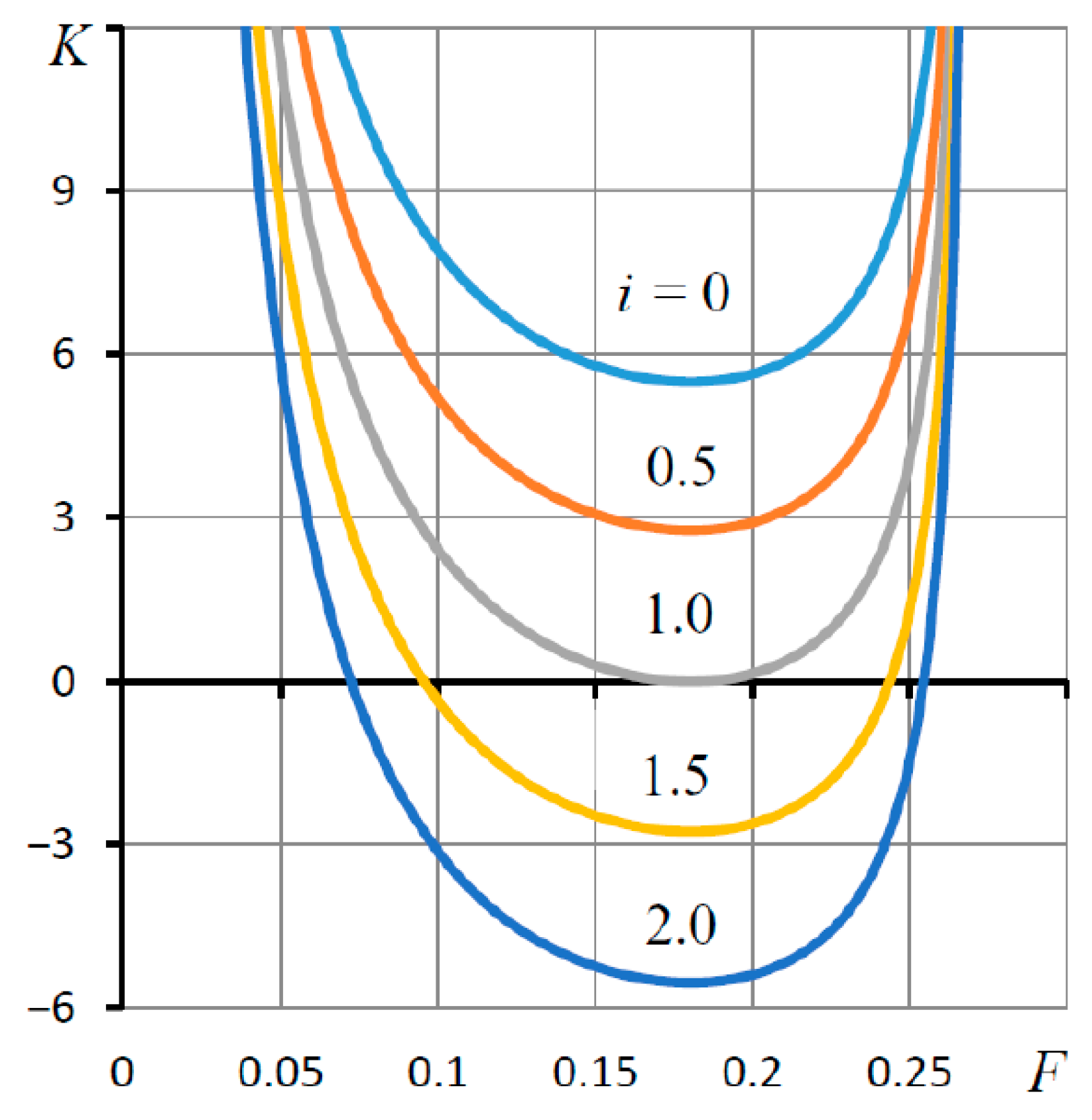
It can be easily observed that this function has a single zero Pt = 2/3, which is always constant and does not depend on the parameters of the thrust bearing, including the coefficient of elasticity Ke. Thus, the optimal mode of least compliance is achieved at χ = 2/3, at which the minima of the dependences K(F) and K(χ) coincide.
Figure 2 shows the graph of the load characteristics for various values of the coefficient of elasticity Ke. The adjustment factor is χ = 2/3, radii R1 = 0.5, R2 = 0.9 > R2,min = 0.736, at which, according to (35), the adaptive function of the thrust bearing can be provided. The coefficient of elasticity of ring 3, according to (38), is Ke0 = 11.2. With this value, the thrust bearing at the “design point” has zero compliance. For each curve in Figure 2, the coefficient of elasticity is set by the formula Ke = i Ke0.
The thrust bearing has a maximum permissible load Fmax = 0.271. The “design point” corresponds to the load F0 = χFmax = 0.181. The curve for i = 0 corresponds to the load characteristic of a conventional thrust bearing, for which the coefficient of elasticity is Ke = 0. The graph shows that with an increase in i and, consequently, an increase in the coefficient Ke, the nature of the curves changes. In this case, in the region of small and moderate values of the load F, the compliance K of the thrust bearing decreases, which can be determined by the change in the slope of the curves.
At Ke = Ke0 (i = 1), at the “design point”, the thrust bearing acquires zero compliance K = 0. A further increase in the coefficient for Ke > Ke0 (i > 1) contributes to the establishment of a negative compliance mode. This mode is characterized by the presence of areas of simultaneous increases in load and clearance. It is in these areas that the thrust bearing acquires an adaptive function as it is able to perform not only the load bearing but also adaptive functions in order to actively compensate for the passive deformation of the elastic system of the machine due to the opposite direction of the force deformation of the lubricating gap of the thrust bearing.
The effect of negative compliance is illustrated by the curves of dependence of the compliance K on the external force F, which are shown in Figure 3. With an increase in the coefficient of elasticity Ke, the compliance K decreases in the range of working loads. At Ke = Ke0, the thrust bearing reaches zero compliance for χ = 2/3 only at the “design point”. At Ke > Ke0, the load range—where the thrust bearing has zero and negative compliance—becomes wider.
In the range of loads F corresponding to negative compliance K, as mentioned above, the thrust bearing is able to carry the load and compensate for the elastic deformations of the machine, that is, it is able to perform an adaptive function. At Ke = 2Ke0, when at the “design point” the negative compliance in absolute value coincides with the compliance of a conventional thrust bearing (Ke = 0), the width of the adaptive load range in negative compliance modes is approximately 75% of the allowable load range width. With Ke > 2Ke0, the adaptive load range will be wider still.
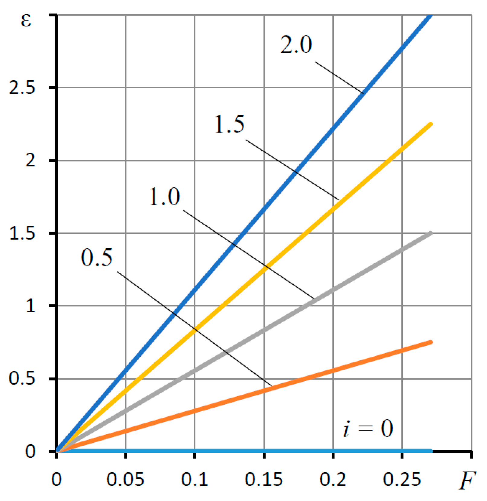
The graph in Figure 4 shows the dependences ε(F) of the deformation of elastic ring 4 on the external load on the bearing. These dependences are linear. To achieve negative compliance at the “design point”, the deformation of elastic ring 3 must meet the condition ε = Ke/Ke0 > 1.
It was mentioned above that as compliance decreases, the dynamic quality of the thrust bearing usually deteriorates, often to the point of loss of stability. Therefore, an important condition for the operability of an adaptive thrust bearing is its dynamic performance, which must meet certain criteria for response speed and stability margin. The speed of response is important so that, with a minimum duration of the transient response, the thrust bearing reaches the calculated negative compliance mode, and the stability margin is important from the point of view of guaranteeing the accident-free operation of the structure.
Thus, to ensure the operability of the adaptive thrust bearing, it is necessary to optimize its parameters based on the study of its dynamic characteristics in order to deliver the structure with sufficient dynamic quality.

4. Dynamic Characteristics of the Thrust Bearing

Let us consider the dynamics of the thrust bearing, which, under the influence of small disturbances of the external load, bring about small fluctuations in the output values relative to their values in the steady (stationary) state. Let us take a unit dimensionless mass M = 1 of shaft 1. This allows us to determine the scale of the current time.

4.1. Linear Model of Thrust Bearing Dynamics

We represent dynamic quantities in the form
F + Δ F ( τ ) , H + Δ H ( τ ) , H s + Δ H s ( τ ) , ε + Δ ε ( τ ) , P t + Δ P t ( τ ) ,
where the first term in the expressions represents the static constituent and the second the small dynamic constituent. After substituting (44) into the nonlinear system of Equations (27)–(30), with its linearization and application to the resulting linear system of equations of the integral Laplace transform [25], we obtain a linear model of the dynamics of the studied thrust bearing in Laplace transforms. Eliminating ΔH, we obtain a system of three equations. The matrix form of this system is
[ ( B 6 s + M s 2 ) B 7 s A 11 ( A 6 + B 8 s ) ( A 6 + B 9 s ) A 7 B 10 s ( 1 + B 11 s ) A 8 ] [ Δ H ¯ s ( s ) Δ ε ¯ ( s ) Δ P ¯ t ( s ) ] = [ 1 0 0 ] Δ F ¯ ( s ) ,
where Δ F ¯ ( s ) is the Laplace transform of a small deviation of the disturbing external force, Δ H ¯ s ( s ) , Δ ε ¯ ( s ) , Δ P ¯ t ( s ) are the transforms of small deviations of the corresponding output quantities, and s is the Laplace transform variable,
A 6 = 3 A 4 H 3 P t , A 7 = A d + A 4 H 3 , A 8 = A 5 K e ,
B 6 = B 0 H s 3 + B 1 H 3 , B 7 = B 1 H 3 , B 8 = B 4 B 3 ,
B 9 = B 4 B 5 , B 10 = K e B 1 H 3 , B 11 = D e + K e ( B 1 H 3 B 2 H t 3 ) .
Applying Cramer’s rule [26] and the algorithm of symbolic expansion of the determinants of polynomial matrices to the solution of the system of linear Equation (45), we determined the transfer function (TF) of the dynamic compliance of the thrust bearing, which is a rational function of the variable s
K ( s ) = Δ H ¯ s Δ F ¯ = b 0 + b 1 s a 0 + a 1 s + a 2 s 2 + a 3 s 3 ,
where
  • a 0 = A 2 A 6 ,
  • a 1 = A 6 [ A 8 ( B 6 B 7 ) + A 2 ( B 10 B 11 ) ] A 7 B 6 A 2 B 8 ,
  • a 2 = A 8 ( A 6 + B 6 B 9 B 7 B 8 ) + A 7 ( B 7 B 10 1 B 6 B 11 ) + A 2 ( B 9 B 10 B 8 B 11 ) ,
  • a 3 = A 8 B 9 A 7 B 11 ,
  • b 0 = A 7 A 6 A 8 ,
  • b 1 = A 7 B 11 A 8 B 9 .
The denominator of the TF (46) is the characteristic polynomial of the system, by which it is possible to judge the stability and quality of transients in a linear dynamic system that describes the dynamics of an adaptive hydrostatic thrust bearing for small deviations of non-stationary quantities from their stationary state.

4.2. Some Considerations Regarding the Methodology for Applying the Linear Dynamics Model to the Study of Sliding Bearings with Liquid and Gas Lubrication

When studying the quality of the dynamics of linear oscillatory systems, the model of the simplest damped harmonic oscillator (DHO) with a second-order characteristic equation is often used
j + c s + m s 2 = 0 ,
where j, c, and m refer to the stiffness, damping, and mass of the oscillator [27], respectively.
According to the Hurwitz conditions, such a system is stable if all the coefficients of Equation (47) are nonzero and have the same sign [28]. As the mass and damping of the generator are always positive, the stiffness should also be positive in stable systems. However, in slide bearings with regulators, which include the studied design, the stiffness, which is the opposite of the compliance, can be infinite or negative. On this basis, it could be assumed that the adaptive bearings of negative compliance are always unstable. However, this assumption is wrong.
In accordance with the basic provisions of the theory of automatic control, the characteristic polynomial of the control object is the denominator of the TF, which for DHO has the form [25]
Φ ( s ) = b 0 a 0 + a 1 s + a 2 s 2 .
The characteristic polynomial of the TF (48) can be reduced to the form of the polynomial (47) by multiplying the first by the constant b0. Studies of adaptive slip bearings show that the sign of static compliance is determined by the coefficient b0 [18,19]. In this case, the coefficients of the denominator polynomial for stable systems always remain positive, which indicates the stability of such dynamical systems. This also applies to the bearing under study. If we turn to TF (46), then only the coefficient b0 depends on the compliance Ke of elastic ring 3, and the coefficient a0 does not. Thus, an oscillator, which is an adaptive hydrostatic thrust bearing, can, like similar structures, have negative static compliance and still be stable.
Note that PFs of the form (48) and (46), which are the Laplace image of dynamic compliance, are rational functions; therefore, from the point of view of the theory of automatic control, the preferred term is “compliance” rather than “stiffness”, the latter term often being used for the analysis of the characteristics of sliding bearings, including adaptive bearings. A particular case of a TF at s = 0 is the static compliance K(0) = b0/a0. Therefore, in this work and other works of the authors on the study of bearings with lubricant flow controllers and displacement compensators that provide the bearings with an adaptive function, the term “compliance” is used [4,5,10,11].

4.3. Dynamic Characteristics of the Thrust Bearing and Their Discussion

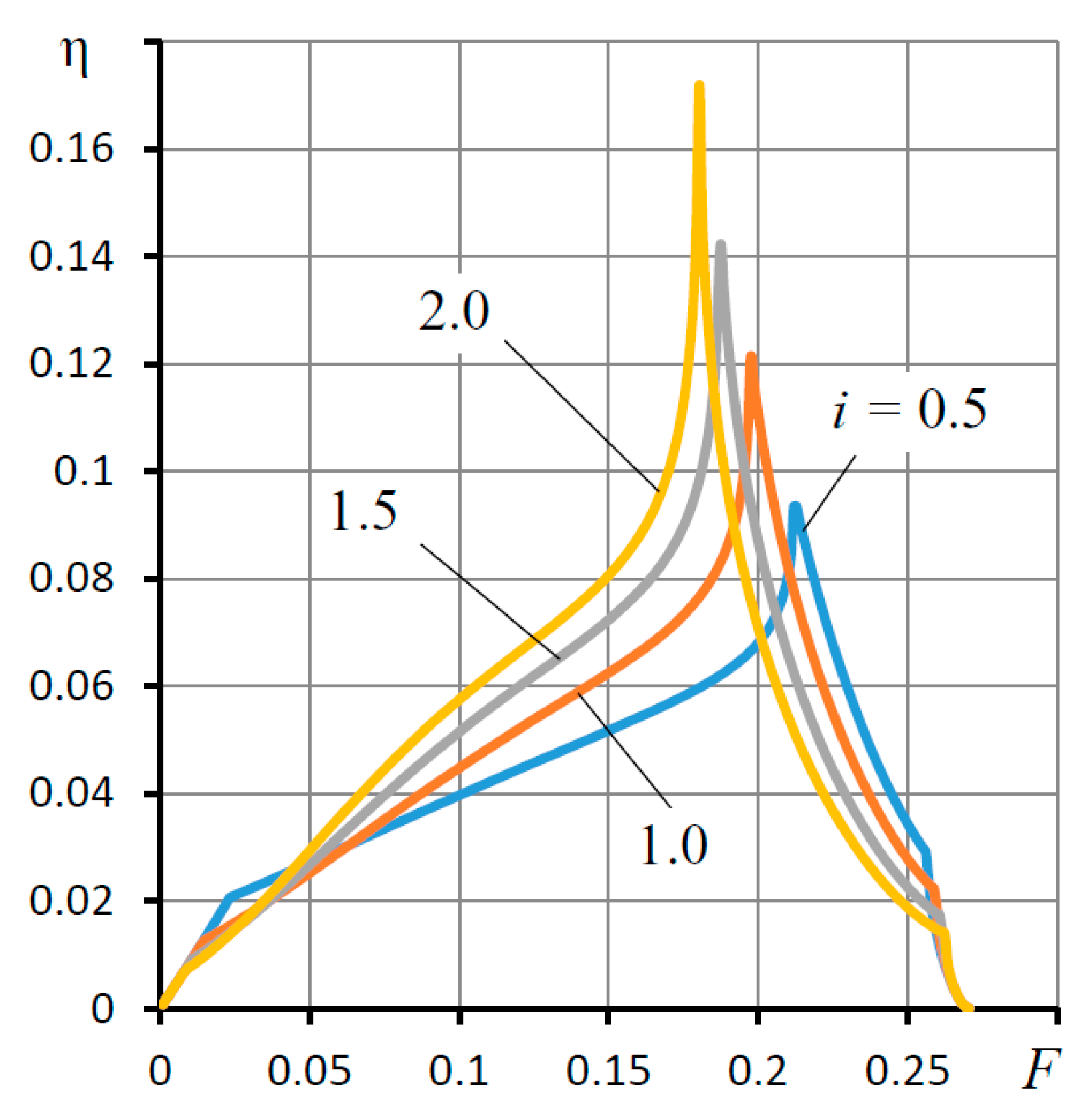
To assess the quality of the thrust bearing dynamics, we used the root criteria—the degree of stability and damping of oscillations over the period [25]. The degree of stability η characterizes the speed of the system, that is, the speed of damping of its free oscillations. By this criterion, one can determine the degree of stability of the system. For η < 0 the system is unstable, for η > 0 it is stable, and for η = 0 the system is on the boundary between stable and unstable. The criterion ξ of the damping of oscillations over a period can be applied to the assessment of the stability margin of the system. The smaller the value of ξ, the greater the oscillation of the transient response and the lower the stability margin of the dynamic system. It is considered that the system is well damped if ξ ≥ 90% [25].
The calculation of the dynamic criteria was carried out for the same parameter values that were used to calculate the static characteristics of the thrust bearing. Three new parameters were added to the dynamics model:
-
Unit mass of the shaft M = 1, taking into account the influence of the force of its inertia;
-
“Compression number” σ, which is a measure of the viscous damping of the lubricant film under pressure;
-
Damping coefficient De of the elastic ring material.
As the first parameter is constant, the other two parameters, as well as the parameter Ht0, are varied.
Calculations have shown that an increase in the parameter Ht0 negatively affects the dynamics of the thrust bearing. The best value is Ht0 = 0.5.
Let us consider the influence of the parameter σ on the dynamic characteristics of the structure. Figure 5 shows the curves of dependence of the degree of stability η on the parameter σ for different values of the elasticity coefficient Ke without taking into account the damping coefficient of elastic ring 3 (De = 0). The graph is constructed for the values of the elasticity coefficient Ke, which provide the thrust bearing negative static compliance in the “design point” mode.
Comparing the graphs of Figure 2 and Figure 3 with Figure 5, we find that the stability (η > 0) of the thrust bearing of negative compliance is provided only for σ > σmin, where σmin is the value of the parameter σ at which the bearing reaches the stability boundary (η = 0). Therefore, for a bearing of negative compliance Ke = 2Ke0, the stability limit corresponds to σmin = 42. At lower values of σ, the thrust bearing is unstable (η < 0). It can be seen that the larger the value of Ke, that is, the lower the compliance K, the larger the σmin corresponding to the stability boundary. This result can be interpreted in such a way that the lower the compliance of the thrust bearing, the smaller the calculated dimensional clearance of the bearing lubricant gap must be to ensure the stability of the thrust bearing at the “design point”.
It is also noteworthy that the dependences η(σ) have a pronounced extreme character, which indicates the existence of an optimal value of the parameter σ = σopt. At this value, the dependence η(σ) reaches a maximum, providing the thrust bearing with the maximum response rate, at which the fastest decay of transient processes is observed. For KeKe0, the optimal performance takes place at approximately σopt = 60.
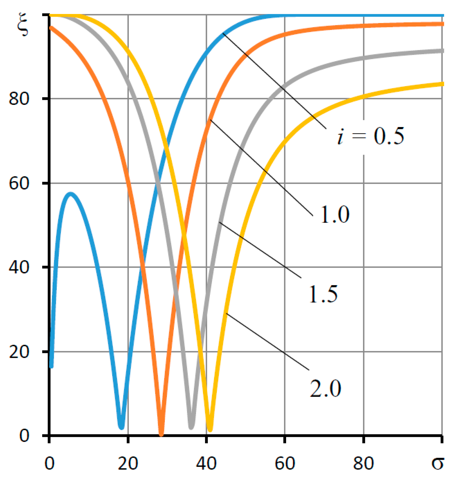
A comparison (presented in Figure 6) of the graph of the dependence of the damping criterion ξ of oscillations for the period on the parameter σ with the graph in Figure 5 shows that, in the stability region at σ < σopt, the transient response has a pronounced oscillatory character (ξ < 80%). When approaching the point σ = σopt, the criterion ξ grows rapidly, which indicates a significant weakening of the oscillation of the transient characteristics and an increase in the stability margin of the thrust bearing. At the same time, for thrust bearings of low compliance (Ke > 2Ke0), the transient characteristics even at σ > σopt remain somewhat oscillatory (ξ < 90%).
The graph in Figure 7 shows the dependences of the degree of stability η on the viscous damping coefficient De for different values of the elasticity coefficient Ke for a fixed value of σ = 60.
The graph shows that the damping of the elastic ring material 3 has a significant impact on the dynamics of the thrust bearing. This influence is especially noticeable with the thrust bearing operating in the modes of negative compliance when the performance at optimal De values can be increased several times. Therefore, for Ke = 2Ke0 without taking into account the coefficient De, the optimal criterion is η = 0.03. As can be seen from Figure 7, with the optimal De = 11, the criterion η = 0.15. That is, the choice of the elastic compensator material, which is optimal from the point of view of damping, enables the speed of the thrust bearing to be increased by a factor of 5.
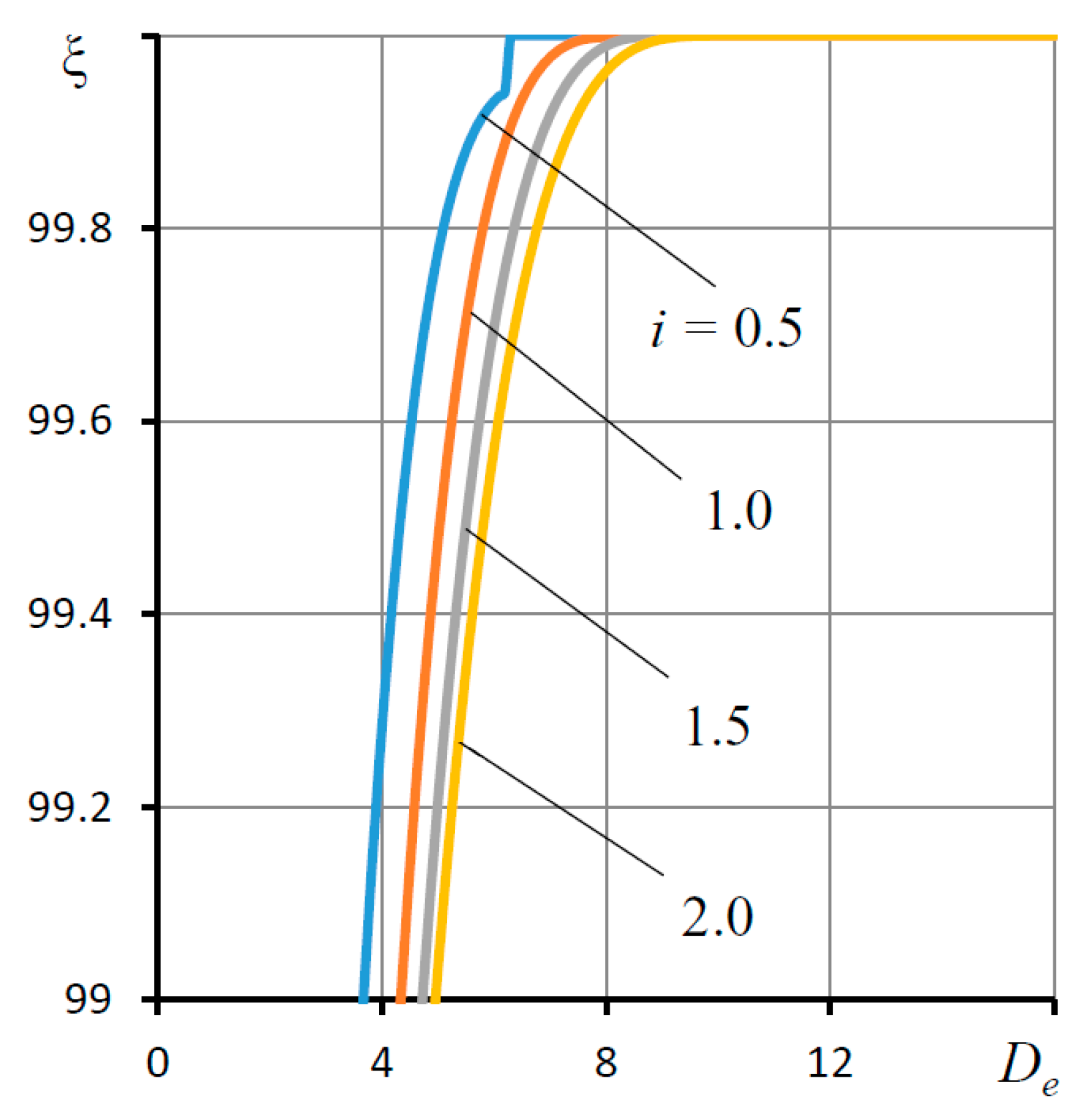
As seen from Figure 8, the parameter De has a particularly significant effect on the criterion ξ of damping of oscillations over a period. For De > 3, the criterion is virtually equal to ξ = 100%. This demonstrates that the corresponding transient processes are aperiodic in nature, indicating a minimum oscillation or even the complete absence of one. This result shows that the negative compliance thrust bearing, designed to take into account the optimal recommendations, has an absolute margin of stability to fluctuations.
It is interesting to consider the quality of the thrust bearing dynamics at various values of the load across the entire range of its variation. The graphs of Figure 9 and Figure 10 show the curves of the degree of stability η and damping ξ of oscillations for the period on the load F for various values of the coefficient Ke at σ = 60 and De = 11.
The graph in Figure 9 shows that the thrust bearing remains stable for all values of the Ke coefficient over the entire range of load variation. In this case, the maximum speed at which the function η(F) reaches its maximum value falls on loads close to the calculated value (F = 0.181). On this basis, a significant conclusion can be reached—that the adaptive bearing can be operable not only in the “design point” mode but also, importantly, across the entire range of permissible loads.
The stability margin of the thrust bearing across the range of permissible loads is represented by the graph in Figure 10. As can be seen from the graph, the thrust bearing has an ideal stability margin over almost the entire range of permissible loads (ξ = 100%). A decrease in the values of the criterion ξ is observed only in the vicinity of the extreme points at which the thrust bearing loses its load-carrying function.
The study of the static and dynamic characteristics of the slotted adaptive hydrostatic thrust bearing shows that an almost ideal quality of its dynamics can be achieved without the use of an external combined throttling system that would over-complicate the design. Viscous damping of the pressurized lubricating film in the gaps of the structure and damping of the material of the elastic ring of the regulator are important resources for ensuring optimal dynamics of the thrust bearing.

5. Checking the Correctness of the Obtained Data

To confirm the correctness of the obtained data, they were compared with the theoretical and experimental data of other authors. The comparison was carried out for hydrostatic thrust bearings, in which ring 4 was motionless, which corresponds to the coefficient of elasticity of the compensator Ke = 0 (absolutely rigid ring 3). The data were compared with the theoretical data from [29] and the experimental results from [30].
Table 1 shows comparative theoretical data on the static load capacity of the thrust bearing for radii r1 = 30 mm, r0 = 40 mm for various values of external pressure ps at pt = 0.5ps.
The presented theoretical results are in good agreement. A slight error is explained by the fact that in [29] a simplified method for calculating the bearing capacity was used, assuming that the pressure of the lubricating film on the surface of the outer ring is equal to half the pressure at the outlet of their supply gap.
Table 2 shows comparative theoretical and experimental data on the static bearing capacity of thrust bearings for radii r1 = 24 mm and r0 = 32 mm for different values of the gap h at an external pressure ps = 0.8 MPa.
A comparison of theoretical and experimental data provides a more significant difference. However, such a result can be considered quite satisfactory as the indicated data on the difference between theory and experiment can be explained by many reasons known to researchers, therefore the experiment as a whole confirms theoretical calculations. This allows us to conclude that for the considered particular case of the mathematical model of the thrust bearing, confirmation of its adequacy has been obtained.
As for the model of the movement of ring 4 on elastic suspension 3, for such a bearing the conduction of an experimental study is being planned, in the process of preparation and implementation of which several important practical problems will have to be solved, which are complex and beyond the scope of this paper. In this regard, the present theoretical study is fundamental to a certain extent, and the data obtained from the verification of a particular case provide reason to trust the calculated data and general conclusions about the performance of the considered design in the context of assessing its quantitative performance characteristics.

6. Conclusions

This paper considered the design of a slotted adaptive hydrostatic thrust bearing with a regulator of the lubricant output flow and conducted a theoretical study of its static and dynamic characteristics. The aim of the study was to test the reliability of the hypothesis that it is possible to obtain a vibration-resistant adaptive thrust bearing of negative compliance without having to use a complex system of external combined throttling by replacing it with a simple slotted throttle. Mathematical modeling of the movement of the thrust bearing and its structural elements was carried out. The paper presented the possibility of a significant decrease in the compliance of the structure, including negative compliance in order to provide an adaptive function, which consists of using the bearing not only as a support but also as an active compensator for the deformation of the elastic system of a metal-cutting machine in order to improve the quality of the metalwork. It was found that negative compliance is provided across a wide range of loads, which can be up to 75% or more of the range of permissible bearing loads. The study showed that with a purposeful selection of parameters that have the main influence on the dynamics of the structure, the considered adaptive hydrostatic thrust bearing can attain an almost ideal quality of its dynamics. Viscous damping of the lubricating film enclosed in the gaps and damping of the elastic ring material of the regulator are important resources for ensuring optimal thrust bearing dynamics.

Author Contributions

Conceptualization, V.K.; formal analysis, A.K.; investigation, S.B., A.S. and L.G.; data curation, O.G., M.B. and L.S.; writing—original draft preparation, V.K.; writing—review and editing, A.K.; project administration, A.K. All authors have read and agreed to the published version of the manuscript.

Funding

This research received no external funding.

Institutional Review Board Statement

Not applicable.

Informed Consent Statement

Not applicable.

Data Availability Statement

The data presented in this study are available on request from the corresponding author. The data are not publicly available due to privacy.

Conflicts of Interest

The authors declare no conflict of interest.

Nomenclature

H, hdimensionless thickness, thickness of the gap
Htdimensionless thickness of the blind gap
Hsdimensionless value of the total gap
εdimensionless deformation of elastic ring 3
K, Kedimensionless compliance of the bearing and elastic ring 3
P (R,τ)dimensionless dynamic pressure in the bearing gap
ptlubricant pressure at the outlet of the gap
pssupply pressure
Qhdimensionless flow rate through the gap
Qtdimensionless flow rate at the inlet to the gap Ht
Qsdimensionless flow rate at the outlet of the gap Hs
Qcdimensionless flow rate through the slotted throttle
r0,r1,r2bearing radii (Figure 1)
Rdimensionless radius
t0scale of current time
Wdimensionless load capacity
ηdegree of stability
μcoefficient of dynamic viscosity of the lubricant
ξdamping of oscillations over the period
χnormalized adjustment coefficient of the external throttling system
σ“compression number”
τdimensionless time

References

  1. Bouyer, J.; Wodtke, M.; Fillon, M. Experimental research on a hydrodynamic thrust bearing with hydrostatic lift pockets: Influence of lubrication modes on bearing performance. Tribol. Int. 2022, 165, 107253. [Google Scholar] [CrossRef]
  2. Michalec, M.; Svoboda, P.; Křupka, I.; Hartl, M. A review of the design and optimization of large-scale hydrostatic bearing systems. Eng. Sci. Technol. Int. J. 2021, 24, 936–958. [Google Scholar] [CrossRef]
  3. Yanqin, Z.; Yi, L.; Shiqian, N.; Zhiquan, Z. Heavy load characteristics of micro-beveled heavy-duty hydrostatic bearing lubricant oil film. Proc. Inst. Mech. Eng. Part J J. Eng. Tribol. 2020, 235, 738–747. [Google Scholar] [CrossRef]
  4. Kodnyanko, V.; Kurzakov, A.; Grigorieva, O.; Brungardt, M.; Belyakova, S.; Gogol, L.; Surovtsev, A.; Strok, L. Theoretical disquisition on the static and dynamic characteristics of an adaptive stepped hydrostatic thrust bearing with a displacement compensator. Mathematics 2021, 9, 2949. [Google Scholar] [CrossRef]
  5. Push, A. Spindle Units: Quality and Reliability; Mashinostroenie: Moscow, Russia, 1992; 288p.
  6. Brzeski, L.; Kazimierski, Z. High stiffness bearing. J. Lubr. Technol. 1979, 101, 520–525. [Google Scholar] [CrossRef]
  7. LaTray, N.; Kim, D.; Song, M. Static performance of a hydrostatic thrust foil bearing for large scale oil-free turbomachines. J. Eng. Gas Turbines Power 2021, 143, 041017. [Google Scholar] [CrossRef]
  8. Brungardt, M.; Shatokhin, S. Spindles with multiply adaptive hydrostatic bearings. Russ. Eng. Res. 2021, 41, 10–15. [Google Scholar] [CrossRef]
  9. Kurzakov, A. Adaptive gas-static spindle bearings. Russ. Eng. Res. 2013, 33, 389–391. [Google Scholar] [CrossRef]
  10. Sawicki, J.; Capaldi, R.; Adams, M. Experimental and theoretical rotordynamic characteristics of a hybrid journal bearing. J. Tribol. 1997, 119, 132–141. [Google Scholar] [CrossRef]
  11. Pourmehran, O.; Rahimi-Gorji, M.; Gorji-Bandpy, M.; Baou, M. Comparison between the volumetric flow rate and pressure distribution for different kinds of sliding thrust bearing. Propuls. Power Res. 2015, 4, 84–90. [Google Scholar] [CrossRef] [Green Version]
  12. Shatokhin, S.; Shatokhin, S. Closed hydrostatic guides of metal-cutting machines. Russ. Eng. Res. 2014, 34, 326–329. [Google Scholar] [CrossRef]
  13. Hesselbach, J.; Abel-Keilhack, C. Active hydrostatic bearing with magnetorheological fluid. J. Appl. Phys. 2003, 93, 8441–8443. [Google Scholar] [CrossRef]
  14. Ow, D.S.; Lee, R.M.; Nissom, P.M.; Philp, R.; Oh, S.K.; Yap, M.G. Inactivating frur global regulator in plasmid-bearing escherichia coli alters metabolic gene expression and improves growth rate. J. Biotechnol. 2007, 131, 261–269. [Google Scholar] [CrossRef] [PubMed]
  15. Lee, J.; Dixon, W.E.; Ziegert, J.C. Adaptive nonlinear contour coupling control for a machine tool system. In Proceedings of the 2005 IEEE/ASME International Conference on Advanced Intelligent Mechatronics, Monterey, CA, USA, 24–28 July 2005. [Google Scholar] [CrossRef]
  16. Kodnyanko, V. Characteristics of a gas-static thrust bearing with an active displacement regulator. Russ. J. STIN 2005, 9, 32–34. [Google Scholar]
  17. Kodnyanko, V.; Shatokhin, S. Theoretical study on dynamics quality of aerostatic thrust bearing with external combined throttling. FME Trans. 2020, 48, 342–350. [Google Scholar] [CrossRef]
  18. Kodnyanko, V.; Shatokhin, S.; Kurzakov, A.; Pikalov, Y.; Strok, L.; Pikalov, I.; Grigorieva, O.; Brungardt, M. Theoretical efficiency study of output lubricant flow rate regulating principle on the example of a two-row aerostatic journal bearing with longitudinal microgrooves and a system of external combined throttling. Mathematics 2021, 9, 1689. [Google Scholar] [CrossRef]
  19. Kodnyanko, V.; Kurzakov, A. Compliance of gas-dynamic bearing with elastic compensator of movement. J. Sib. Fed. Univ. Eng. Technol. 2017, 10, 657–663. [Google Scholar] [CrossRef]
  20. Shatokhin, S.; Kodnyanko, V. Radial gasostatic bearing-seal with opposite internal gas flow compensation. Sov. J. Frict. Wear 1984, 5, 32–35. [Google Scholar]
  21. Kodnyanko, V. Method for calculating the static characteristics of radial hydrostatic compensator of machine tool bearings deformation. Period. Polytech. Transp. Eng. 2021, 49, 114–119. [Google Scholar] [CrossRef] [Green Version]
  22. Kazama, T.; Yamaguchi, A. Hydrostatic thrust bearing-theory and experiments. Tribology 1968, 1, 62. [Google Scholar] [CrossRef]
  23. Demidovich, B.; Maron, I.; Shuvalova, E. Numerical methods of analysis. In Approximation of Functions, Differential and Integral Equations, 5th ed.; Lan: Moscow, Russia, 2010; 400p. [Google Scholar]
  24. Wulandari, S.; Iswanto, B.; Sugihartono, I. Determination of springs constant by hooke’s law and simple harmonic motion experiment. J. Phys. Conf. Ser. 2021, 2019, 012053. [Google Scholar] [CrossRef]
  25. Besekersky, V.; Popov, E. Theory of Automatic Control Systems; Profession: Saint Petersburg, Russia, 2003; 752p. [Google Scholar]
  26. Ricardo, H. A modern Introduction to Linear Algebra; CRC Press: New York, NY, USA, 2009; 670p. [Google Scholar]
  27. Narendra, K.; Shorten, R. Hurwitz stability of metzler matrices. IEEE Trans. Autom. Control 2010, 55, 1484–1487. [Google Scholar] [CrossRef]
  28. Baldiotti, M.; Fresneda, R.; Gitman, D. Quantization of the damped harmonic oscillator revisited. Phys. Lett. A 2011, 375, 1630–1636. [Google Scholar] [CrossRef] [Green Version]
  29. Shatokhin, S.; Pikalov, I. Hydrostatic bearing. Invent. Eng. 2007, 1, 4. [Google Scholar]
  30. Markhel, I. Machine Parts; Mashinostroenie: Moscow, Russia, 1986; 448p.
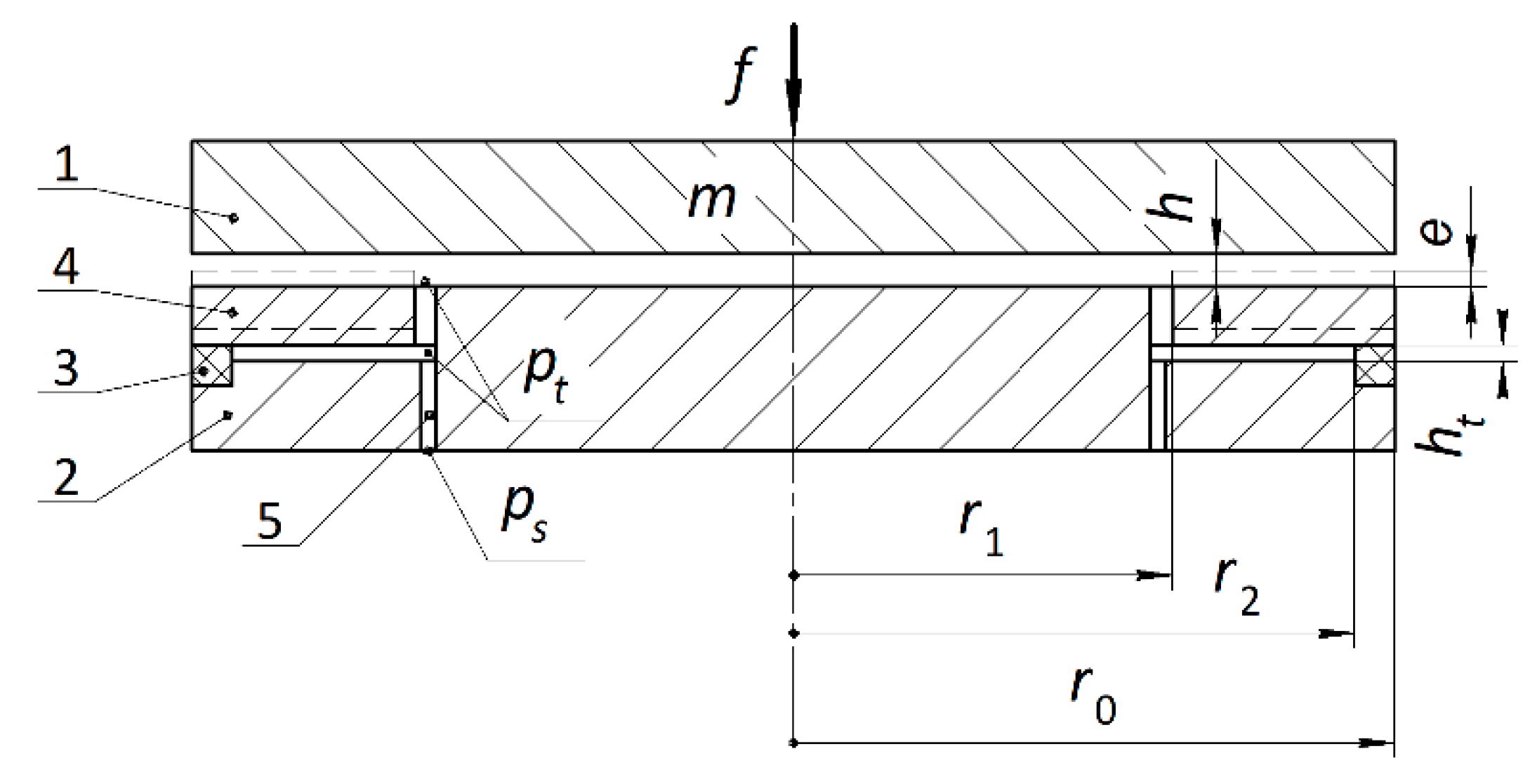
Figure 1. Design of slotted adaptive hydrostatic thrust bearing.
Mathematics 10 00355 g001
Figure 2. Load characteristics Hs(F) of the thrust bearing for different values of the elasticity coefficient Ke = i Ke0.
Mathematics 10 00355 g002
Figure 3. Dependences of compliance K on external force F for different values of the elasticity coefficient Ke = i Ke0.
Mathematics 10 00355 g003
Figure 4. Characteristics of deformation ε(F) of elastic ring 3 for different values of the elasticity coefficient Ke = i Ke0.
Mathematics 10 00355 g004
Figure 5. Dependences of the degree of stability η on the “compression number” σ for different values of the elasticity coefficient Ke = i Ke0.
Mathematics 10 00355 g005
Figure 6. Dependences of the criterion ξ of damping of oscillations for a period on the “compression number” σ for different values of the elasticity coefficient Ke = i Ke0.
Mathematics 10 00355 g006
Figure 7. Dependences of the degree of stability η on the viscous damping coefficient De for different values of the elasticity coefficient Ke = i Ke0.
Mathematics 10 00355 g007
Figure 8. Dependences of the criterion ξ of damping of oscillations for the period of the viscous damping coefficient De for different values of the elasticity coefficient Ke = i Ke0.
Mathematics 10 00355 g008
Figure 9. Dependences of the degree of stability η on the load F for different values of the coefficient of elasticity Ke = i Ke0.
Mathematics 10 00355 g009
Figure 10. Dependences of the criterion ξ of damping of oscillations for a period on the load F for different values of the elasticity coefficient Ke = i Ke0.
Mathematics 10 00355 g010
Table 1. Theoretical data comparison.
Performance
Parameter
Supply
Pressure (MPa)
Computational
Data
Data [29]Error
(%)
Load capacity
(N)
0.43173221.7
0.86346441.7
1.29509661.7
1.6126712881.7
2.0158416101.7
Table 2. Theoretical and experimental data comparison.
Performance
Parameter
Bearing
Gap (µm)
Computational
Data
Data [30]Error
(%)
Load capacity
(N)
1038632017
1536530716
2034329514
Publisher’s Note: MDPI stays neutral with regard to jurisdictional claims in published maps and institutional affiliations.