Article

Signal-Level Fusion Approach for Embedded Ultrasonic Sensors in Damage Detection of Real RC Structures

by
Joyraj Chakraborty
* and
Marek Stolinski
NeoStrain Sp. z o.o., Lipowa 3, 30-702 Krakow, Poland
*
Author to whom correspondence should be addressed.
Mathematics 2022, 10(5), 724; https://doi.org/10.3390/math10050724
Submission received: 31 December 2021 / Revised: 20 February 2022 / Accepted: 21 February 2022 / Published: 24 February 2022

Abstract

:
This paper presents a novel methodology to fuse signals from multiple ultrasonic sensors and detect cracks in the reinforced concrete reference structure using nondecimate discrete wavelet transform. The behaviour of a reinforced concrete structure subjected to operational changes is considered. The changes/damage detection procedure is based on a novel sensor fusion method. Several advantages of the proposed approach using the sensor fusion method with respect to features from single pair of sensors were shown and discussed based on the tested objects. A CWT feature-based approach is considered to extract damage-sensitive features. Experimental results using the proposed approach show a probability of detection greater than 94% when detecting cracks due to quasistatic load. Due to the comprehensive effectiveness and low computational complexity, the proposed approach could be performed in large real structural damage assessment problems as well.

1. Introduction

The ambitions of humans to conquer new spaces has always led us to imagine, draw and design a great magnitude of civil structures. This induces the development of appropriate materials to reach this goal. Today, concrete is one of the most common materials used to build superstructures. However, concrete is a material that shows changes over time. Thus, several factors lead these changes, such as the mechanical loading of the structure, the environment or attacks sustained over time, to degrade the material. These can lead to variations in the mechanical properties of the structure. Hence, how can we ensure the safety of this structure, which is under the heavy traffic and harsh environmental conditions? The answer is preventive maintenance, but how can we optimize it? An approach is given through the long-term monitoring of structures, named Structural Health Monitoring (SHM) [1]. The SHM system uses measurement technologies located in the different geometric areas to detect these changes in structures.
Applications such as traffic controls, security and monitoring systems are an integral part of superstructures. Monitoring system is a significant requirement for today’s civil structure under the name Structural Health Monitoring (SHM). Several Non-Destructive Testing (NDT) measurement techniques have been used for SHM system [2]. The quality problems encountered in the concrete structures appear at different stages of the realization of the work; for this reason, increased demand for more precise measurement techniques and, at the same time, more flexible evaluation of the quality of the concrete can be observed. Thus, to address these problems, a range of in situ tests called “non-destructive tests” have been developed. Many parameters play an important role here, however, the main thing which restricts the performance of these systems in many cases is the limited measurement areas of the sensors. In fact, sensors have some characteristics which the limit range of their measurement area.
In civil engineering, the available NDT techniques are listed as follows: ultrasound; impact-echo; acoustic emission; strain gauges; fiber optics; and, more locally, rebound hammer, etc. [2,3,4,5,6,7]. Among them, ultrasonic testing (ultrasonic pulse velocity), impact echo, acoustic emission and rebound have been the most common techniques for many years. It is well known that several NDT techniques possess different advantages and disadvantages [8]. However, the main disadvantages are their cost and capability for long-term monitoring (for most of the techniques). In spite of that, ultrasonic echo and pulse velocity techniques are used frequently in civil structures (as they are not bulky or expensive). Ultrasonic measurement technique is based on the analysis in time or in frequency of the signal coming from an ultrasonic mechanical wave, typically less than 200 KHz, which propagates inside or on the surface of a structure. The propagation of mechanical waves makes it possible to follow the maturity of the material, to determine the degree of its homogeneity, and to detect defects (cracks, voids, etc.). They are sensitive to the mechanical properties such as resistance to compression, tension, the modulus of elasticity, and also to certain physical properties (e.g., cracks) [9,10]. Usually, ultrasonic equipment is placed on the surface of the structure. Here, the contact between the surface and the ultrasonic sensors are usually coupled with vaseline or glycerin, but these are not always equal or of a stable quality [10].
New doors for civil structural health monitoring based on coupled embedded ultrasonic methodology (without contacting surface) are in the development phase. And this methodology does not need a trained operator to carry out the test. According to this, BAM (Bundesanstalt für Materialforschung und -prüfung) developed a novel ultrasonic transducer, which can be permanently embedded in concrete. The measurement techniques used there are based on at least two transducers (one transmitter and one receiver). The main benefit of these embedded ultrasonic sensors are the constant coupling inside the concrete, and the sensors are also suitable for the permanent investigations of concrete structures [11]. The good coupling increases the sensitivity of the sensors to farther events, the consistency of the coupling allows monitoring for longer periods of time, and the embedding in deeper areas of a component offers the opportunity to monitor areas that are no longer observable from the surface.
A wide range of studies has been presented on the application of embedded ultrasonic sensors to evaluate structural changes, such as during crack opening and closing, in particular, or velocity changes due to damage in the form of an artificial crack [11,12,13,14,15,16]. The majority of these research studies used more than two embedded sensors which were located in different geometric areas. However, the detection from each pair of the sensors has been investigated. Yet, the combination of the multiple pairs of sensors located in same geometrical area remains a great challenge for this technique, despite the special interest in making such degradation detection, since these decisions may lead to early crack detection. Employing multiple pairs of sensors and combining the two sets of signal, a fused representation is generated which illustrates different aspects of the object at once and, thus, offers clarified interpretability. The primary goal of the data fusion is to improve and simplify the interpretability of the measurement results. For this purpose, the individual measurement results are superimposed by means of various signal processing operations. Depending on the choice of operations, it then leads to an integration of the information that is essential for the postprocessing of the data. Several data-fusion methods have been proposed in recent years. An introduction and comprehensive survey to the area of fusion is provided in [17,18]. In [19], the analysis from multiple NDT techniques (by X-ray radiography, ultrasonic C-scan) were fused to construct a complete map of the damage region in the fiber-reinforced composite material. The authors intend to take advantage of both these methods by fusing the two methods. In [20], ultrasonic image was fused with electromagnetic testing images through the AND logic operation to detect simulated defect on an aluminium plate. Mendoza et al. [21] combined data from four NDT techniques for the evaluation of apples’ firmness and sugar concentration. The authors used a linear regression technique to disclose the nondestructive prediction between sensor data and apple characteristics and concluded that prediction was improved over single sensor analysis. In [22,23], the Bayesian inference and wavelet-based methods were applied to fuse the acquired images from ET C-scan and infrared (IR) thermographic testing. In [24], different methods for fusion were reviewed, including the Kalman filter [25], Bayesian estimation theory, statistical decision theory, Dempster–Shafer evidential reasoning theory and fuzzy logic. In the above-cited works, most of the researchers worked on combining different NDT methods to obtain comprehensive results. Each NDT technique has advantages and limitations. In [26], sensitivity kernel was used to generate three-dimensional images that show multiple cracks in the concrete structure. In another study [27], the authors showed the benefit of multiple features for concrete structures. Although it indicates the benefits of using sensor fusion, still more work should be focused on the potential of sensor fusion technology. So it can invade precisely detecting damage, as well as the location of the damage. However, there is limited work focusing on combining multiple sensors for same NDT techniques, that are located in different geometrical areas. Indeed, each sensor pair measures specific physical properties due to their fixed position and reveals only a specific feature of the tested structure. On the other hand, combining the sensors can gather additional information about the size or location of a damage and reduce false alarm rate. This extra information may help the owners of structures to assess the repair time.
This paper focuses on the monitoring of a concrete reference structure subjected to tensile loading resulting in failure. The monitoring is conducted with use of wave propagation generated and measured by the multiple embedded ultrasonic transducers. By using these transducers, the crack initiation and propagation can be identified by using time–frequency method damage index (DI). The embedded transducers are installed on the top and bottom of the concrete reference structure. The combining of these multiple sensors located on the top and bottom of the specimen and the analysing of time and frequency characteristics of the ultrasonic signals propagating through the whole element are used to detect concrete cracking and for the evaluation of the element’s condition. In this paper, the cracks are caused by static load application on a reinforced concrete beam equipped with four embedded ultrasonic sensors in a four-point arrangement.

2. Methodology

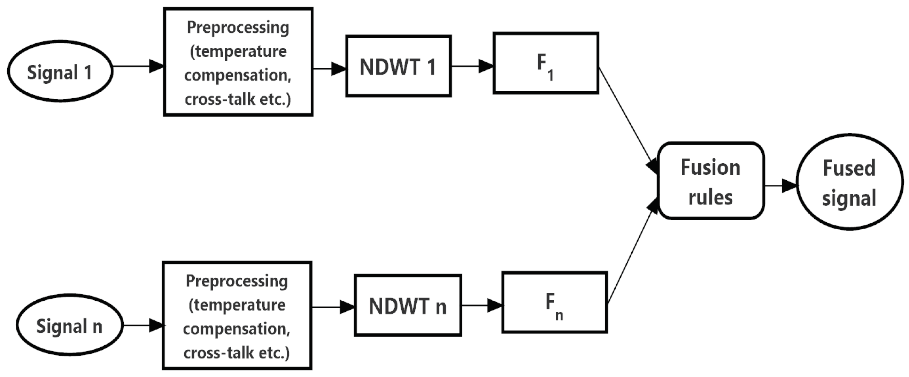
2.1. Fusion Algorithm

Signal-level fusion is one of the significant procedures used to combine information and acquired meaningful features from the sensors located in different positions (geometrically). There are different techniques which have been used in image fusion, such as Simple average, Intensity and Saturation (HIS), Principal Component Analysis (PCA), Discrete Cosine Transform (DCT) and Discrete Wavelet Transform (DWT), etc. Here, we describe some of their advantages and disadvantages.
In HIS fusion method, the IHS space is converted from the Red, Green and Blue (RGB) space of the Multispectral image. The intensity factor I is replaced by the panchromatic image (PAN). Then, the reverse transform is applied to obtain an RGB image as an output. HIS used the intensity part by reversing to RGB colour for fused image. However, saturation is dependent on luminance value [28].
The PCA method is a statistical method which is mainly used to dimension reduction studies [29]. In SHM, PCA has been used to distinguish between changes due to load/damage from environmental changes. PCA extracts the information with highest influence and reduces redundant information, and, in so doing, increases the signal-to-noise ratio. In PCA, high- and low-frequency components are obtained separately by filtering and finally added together as a fused outcome. However, PCA results are not sensible if the feature components do not follow the linear combination.
In DCT, the sum of cosine functions of different frequencies is used to produce the fused image. DCT coefficients are obtained from different blocks, and then averaged to obtain fused DCT coefficients. The limitation of DCT is the loss of time information [30].
The DWT provides a structure, where analysed input signals pass through a filter with different cut-off frequencies at different scales [31]. Hence, signals are converted to a frequency domain. The output comes as a set of detail coefficients from the high-pass filter and a set of approximation coefficients from the low-pass filter. Using the fusion rule and inverse wavelet transform, one can produce a fused output. The limitation of DWT is that when the signal is shifted slightly, the amplitude of the wavelet coefficients changes due to the lack of shift invariance.
There is a simple approach to overcome this problem, named Non-Decimated Wavelet Transform (NDWT) [32]. The NDWT is an undecimated form of a conventional DWT based on Mallat’s multiresolution algorithm. It is performed by the insertion of zeros in the filter for upsampling and suppressing the downsampling step of the decimation algorithm. Its main advantage is translation invariance with respect to DWT, since the main signal is not decimated, so the resolution can be maintained, and signal-to-noise ratio increases [33]. These characteristics make this algorithm suitable for change detection, signal fusion, and feature extraction.
The NDWT decomposition uses the scaling function (low-pass filter) and the wavelet function (high pass filter) [34]. These functions satisfy the two-scale relation:
2 1 2 ϕ ( t 2 k ) = n = h ( n 2 k ) ϕ ( t n )
2 1 2 ψ ( t 2 k ) = n = g ( n 2 k ) ϕ ( t n )
where h n and g n are the impulse responses of low-pass and high-pass mirror filters. The jth level of decomposition is shown in Figure 1. The decomposition formulas of NDWT are as follows:
A j + 1 [ l ] = n = k h [ k ] A j [ l + 2 j k ]
D j + 1 [ l ] = n = k g [ k ] A j [ l + 2 j k ]
where A j + 1 [ l ] and D j + 1 [ l ] are the low-frequency and high-frequency components of the NDWT respectively. h [ k ] and g [ k ] are upsampled by 2 j when the j-level is processed, which results in a constant length of A j and D j . The inverse formulas of NDWT (INDWT) are as follows:
A j [ l ] = 1 2 [ ( l ( h j A j + 1 ) [ l ] + g j D j + 1 ) [ l ] ]

2.2. Fusion Methodology

As summarized in Figure 2, the signal-processing approach consists of three steps.
Figure 2 illustrates the proposed methodology for signal level fusion, which is composed of three stages, namely, preprocessing, NDWT, feature extraction, and feature fusion. The preprocessing stage is divided into two steps: remove temperature effect, then cross talk and normalization. In the first step, the temperature effect was detected from input signals with the help of general baseline subtraction. In the second stage, the normalization of the signal in a proper manner is performed in order to align the signal for fusion. The process of feature extraction is shown in Figure 2. The preprocessed signal is firstly decomposed into different sub bands using NDWT as shown in Section 2.1. The types of wavelet and their order have crucial influence on the effectiveness and accuracy of change/damage detection during the analysis. However, there are no strict rules for the selection of wavelets for damage or change detection in SHM. In previous studies, the author has shown that low-order wavelet gives the best results [35]. Therefore, we selected a low-order biorthogonal wavelet to extract features from the signals. With the level L and wavelet selected appropriately, based on NDWT coefficient sets, A j [ l ] , D j [ l ] , the principal features at different scales were extracted. Therefore, the characteristics of changes (damage) in both geometric locations in the material were preserved and transformed into NDWT domain. Let the two ultrasonic signals from two pairs of sensors be F 1 and F 2 , and F will be the the fused signal. Simple fusion rules were applied to these coefficients.
The fusion rule plays a vital role in signal-level fusion algorithms. The fusion rule is the main processing step that determines the formation of fused multiscale representation from source signals. Most of information (changes, damage) content will be available in low-frequency and high-frequency coefficients; hence, the average with baseline modulated fusion rule has been used for fused multiscale representation. Here, F 2 is less influenced by cracks and noise (when the two pair of sensors perpendicular and close to each other); therefore, the baseline is modulated with signals from F 2 to obtain an optimal fusion output. Equations (6) and (7) are used to compute weighted-averaging fusion rules.
A j [ l ] = ( A j [ l ] F 1 + ( ( 1 A j [ l ] F m ) A j [ l ] F 2 ) ) / 2
D j [ l ] = ( D j [ l ] F 1 + ( ( 1 D j [ l ] F m ) D j [ l ] F 2 ) ) / 2
where F 1 represents the signal from sensor pair 1, F 2 represents the signal from the sensor pair 2, and F m represents the baseline signal from undamaged condition. Based on (5), the inverse non-decimated discrete wavelet transform was performed to reconstruct the fused signal from the combined new feature set A j [ l ] , D j [ l ] .

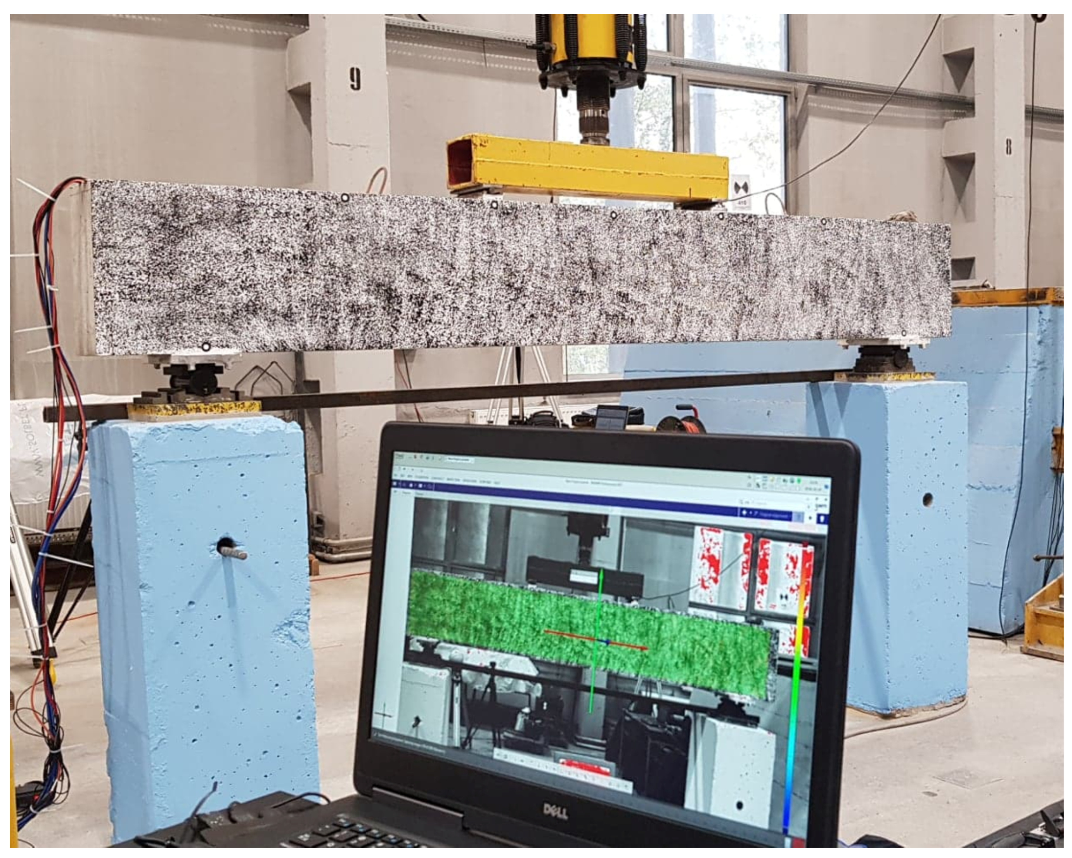
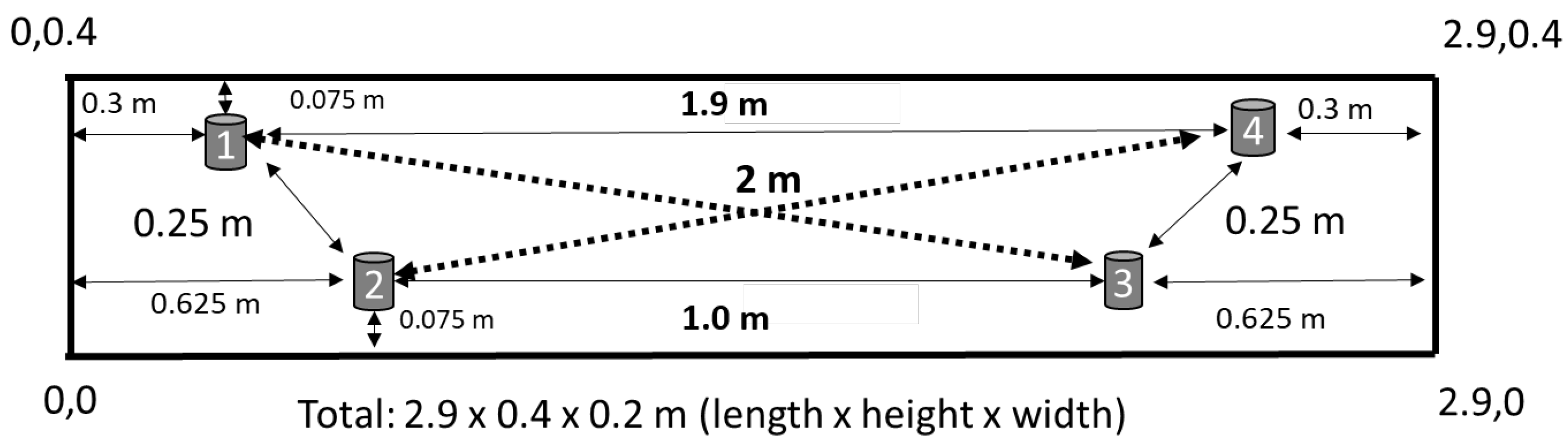
3. Experimental Program

The four-point bending test on the benchmark RC structure was used as a test of the quality and sensitivity of the proposed fusion techniques for embedded ultrasonic sensors.

3.1. Experimental Apparatus

To perform the four-point bending test, the hydraulic jack and a load cell ZR DIORA®—model 25 set to transfer two-point force (Figure 3) were mounted in middle of the beam. To maintain a controlled schedule, an analogue controller was used to operate the loading machine. Since the main purpose of these studies is to evaluate the proposed fused signals for cracks evolution and the damage level with the increasing load using ultrasonic techniques (see Figure 4), we are presenting also the force and deflection. The loading schedule was steady at the beginning on 1 kN/min till 108 kN, and then schedule changed to 5 kN/min (Figure 5), that initiated suitable stress/strain state in the tested RC structure.
During the preparation of the benchmark RC beam, the sensors were concreted. The embedded ultrasonic sensors were attached with a special ring connected with rebar, and vibrating wire strain gauges were attached with top and bottom reinforcement. These new ultrasonic sensors specially suitable for RC structure for monitoring purposes (see [18] for more details), were attached on four vertical stirrups. The position of ultrasonic sensors are shown in Figure 4.
The data acquisition from ultrasonic measurement system was made seven times per minute and customized software used to store the acquired signals in the local disk (for more information see [36]). During the loading schedule, ultrasonic waves were transmitted and propagated through the benchmark RC structure (e.g., sensor 1 transmitted the signal, and, after propagation, sensor 2 registered that signal). Figure 5 shows the loading schedule and deflection corresponding to number of ultrasonic measurements. It can be observed that cracking initiated around at 42 kN.
The examples of the ultrasonic signals acquired from sensor pairs 01 and 03 are shown in Figure 6. It can be seen that at the initial stage, no significant differences were visible in the measured time signals (e.g., for the interval of 0–10 kN). Then, the amplitude started to decrease with the increase of the external loading.
However, one can see that it is difficult to conclude damage/change detection from these raw signals. Therefore, we used a signal processing method to extract meaningful features from the signals registered from both pairs of the sensors (top and bottom). As the sensors were installed at the top and bottom of the benchmark structure, the influence due to changes in the structure could be different. For this reason, we analysed signals from two sensor pairs located in a cross of each other (same distance), and then compared them with proposed fusion techniques.

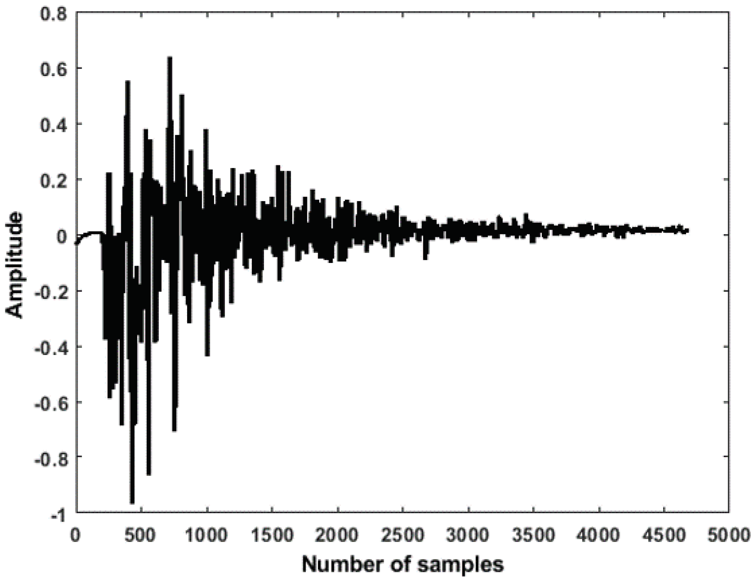
3.2. Time-Frequency Feature Extraction

The interpretation of measured signals in the frequency domain was performed by the Continuous Wavelet Transform (CWT). The CWT function was used since CWT is an effective signal processing approach, used to detect changes/cracks in many applications due to its very high sensitivity to even tiny disturbances in the time-domain signal. CWT-based methods are used for the detection and localization of damages in many applications [37,38,39]. A CWT-based change matrix is developed to evaluate the changes in the structure and propagation of crack. The main procedures to compute the change/damage index matrix is the following:
C W T e = i = 1 i = n x j , i 2 ,
C W T c = j = 1 n ( C W T e , j C W T e , 1 ) 2 j = 1 n ( C W T e , 1 ) 2 .
where the matrix element C W T c represents the CWT-based index of changes associated with the time histories of each pair of the sensors.

4. Test Results and Discussion

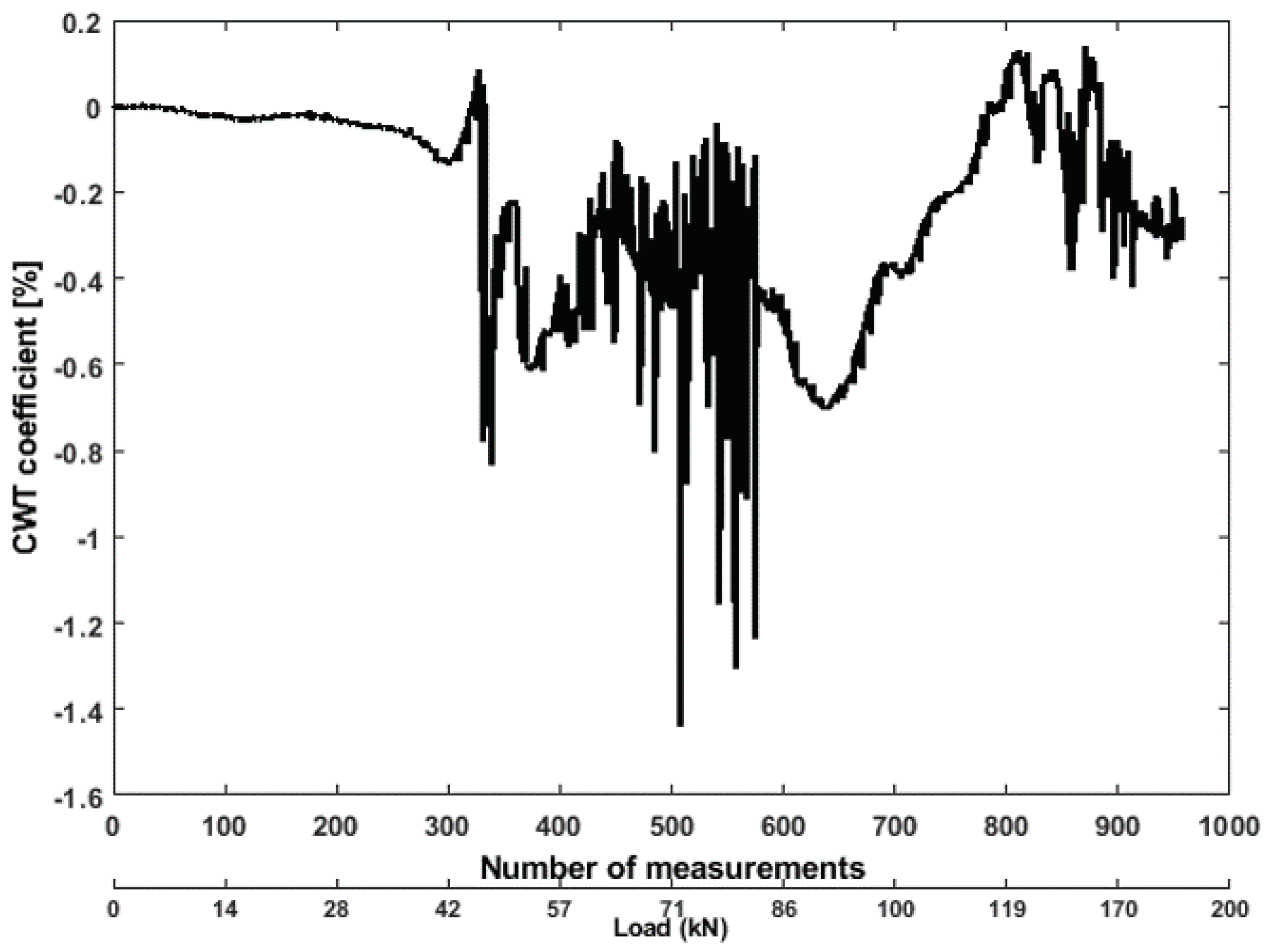
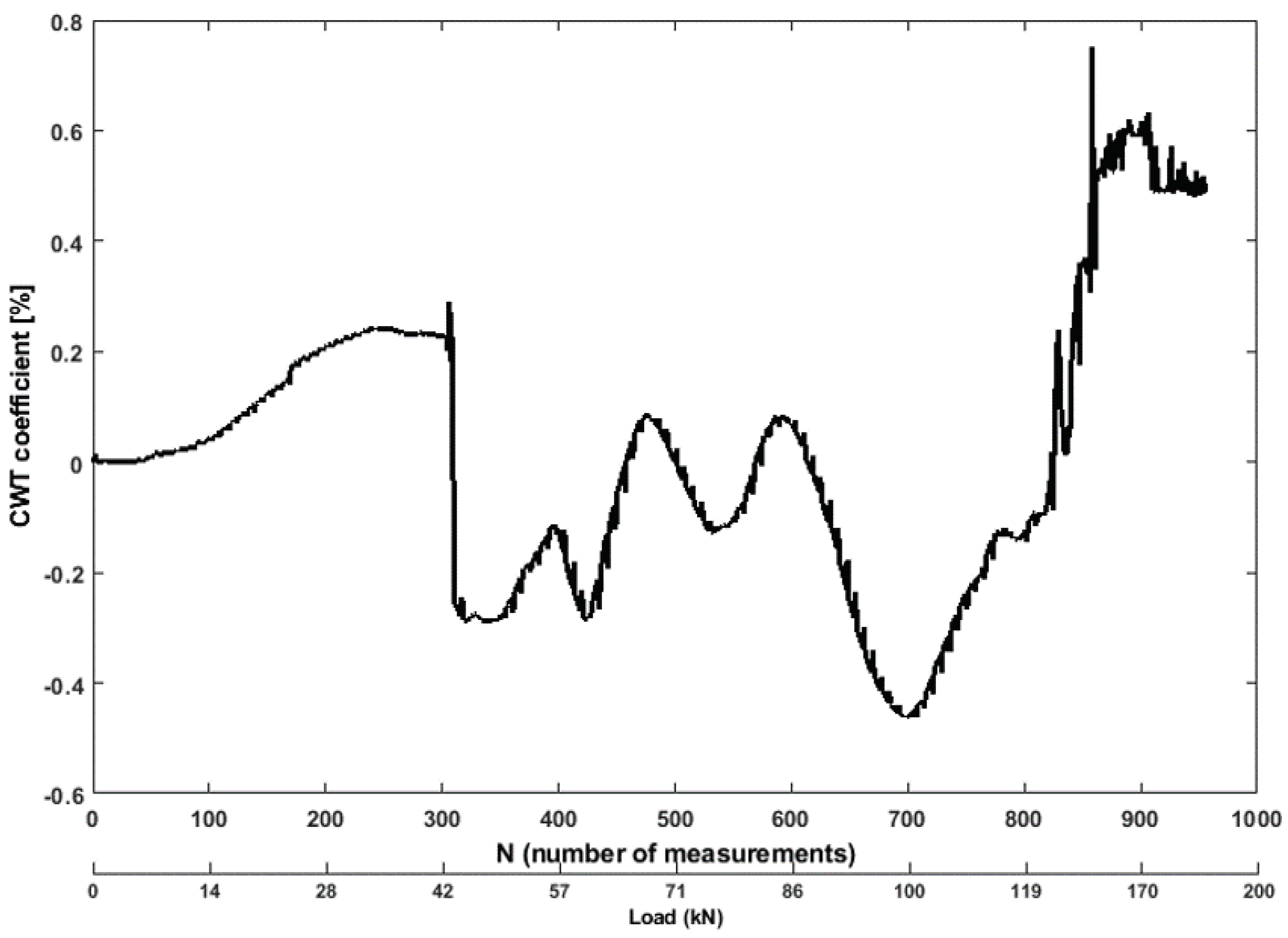
4.1. CWT-Based Signal Processing

Figure 7 and Figure 8 show the CWT coefficient values of the signals registered at sensor pairs S01-R03, and S02-R04, for the benchmark RC structure. The energy of a signal is derived from the CWT transform from the consecutive measurements of propagating ultrasonic waves. The extracted feature from ultrasonic signals analysing the time–frequency domain is more meaningful than time domain analysis. An energy vector is introduced by evaluating the energy of each time interval from the resulting scalogram to show the energy diffusion towards the frequency bands. The first energy coefficient index corresponds to the first stages of wave traveling in the benchmark structure, which is of 0.20% with respect to unloaded state of the tested structure. The results indicate that the coefficients fluctuating as the bending tensile level increases between 36 kN to 48 kN in the beam, and then it ultimately decreases as the load increases between 49 kN to 60 kN. This is because the most of the cracks appear in the general direction of the concrete surface. In the second stage, with the loading schedule between 80 kN to 120 kN, the coefficient is steady, which was obvious as no new cracks appear. Ultrasonic wave propagates in such a direction, therefore, it may miss propagating cracks. The wavelet coefficients are low in general, since the benchmark structure has been destroyed by the horizontal splitting cracks that discontinued the propagation of ultrasonic waves through the concrete.
It is difficult to find the difference of the coefficient between both pairs of the sensors. As from the previous studies, the results show that CWT has a poor performance in detecting the damage from undamaged states [37,40]. Therefore, we are evaluating the proposed signal level fusion technique to improve damage detection.

4.2. Signal Level Fusion

The 1-D ultrasonic signals from both pairs of sensors attached in the benchmark RC structure were processed by using the proposed fusion algorithm presented in Section 2.1. The example of the fused ultrasonic signals is shown in Figure 9.
Figure 7. Values of CWT coefficient feature from ultrasonic pair S01R03 time histories.
Mathematics 10 00724 g007
Figure 8. Ultrasonic signals from sensor pair S02R04 for different load levels.
Mathematics 10 00724 g008
Figure 9. Exemplary ultrasonic signal after fusion.
Mathematics 10 00724 g009
To evaluate the SNR for a fused signal, the following formula was used.
S N R = P s P N
The results of fusion clearly show (see Table 1) that the fused signal reveals less noise influence than the signals from both pairs of transducers before the application of the fusion procedure. One should remember that here we are considering a diffused signal, which is a strong reflection dependent on the particles of material.
To evaluate the fused signal, CWT feature is extracted from the fused signal time histories. From Figure 10, it can be observed that the coefficient decreases with the bending as the level increases between 30 kN to 40 kN in the beam. Then coefficient was fluctuating due to energy attenuation, which indicated microcracks. The coefficient was much more steady compared to results from both pairs of sensors, which reduces the false alarm rate. As depicted in Figure 10, the fused signals based on averaging rules enhanced the damage detection to some extent.

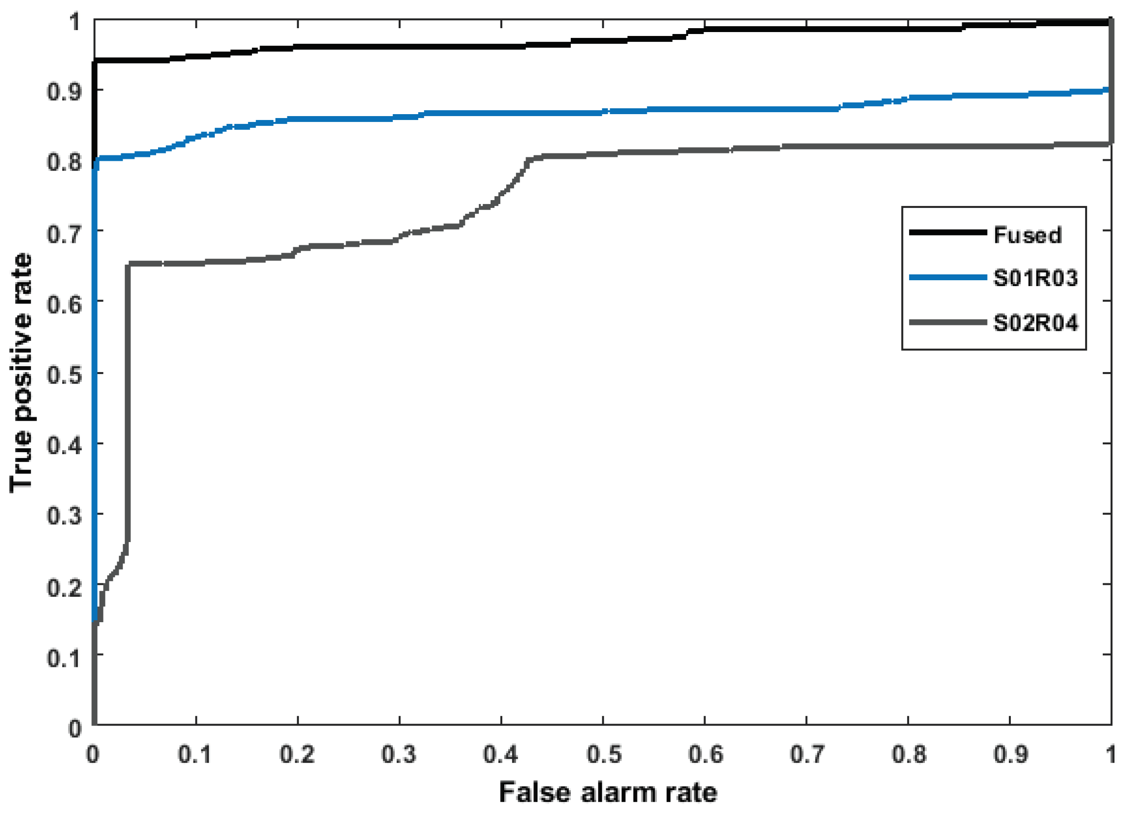
4.3. Feature Comparison Using ROC

The performance of these features is analysed also using ROC curve (for more information see [41]). For each of the features, a predetermined threshold is swept over the range of the feature values of each of the transducer pairs (computed at several times in the experiment), and the probability of detection (true positive rate) is plotted versus the false alarm rate (FAR). A perfect detector, one that calculates the features accuracy to classify the two states, measures the value area under the curve (AROC). The CWT features from the ultrasonic signals (for both pairs) are compared with the fused signal in Figure 11 via their ROC curves. The results indicate that all the features performed well in their capability to detect crack opening and propagation as well as several states in the appearance of noise. However, after using the proposed fusion algorithm, the coefficient performed better (AUC = 0.979 see Figure 11) to classify damage from the undamaged state in this benchmark structure. Since most of the cracks appeared in the middle part of the beam and few in the side, this result is not unexpected from the sensor pair S01-R03, because signals had strong effects compared to the signals recorded in the top pair (S02R04). After averaging the NDWT coefficients of ultrasonic signals by the baseline signal set, the crack information was highlighted more obviously than the other two pairs.

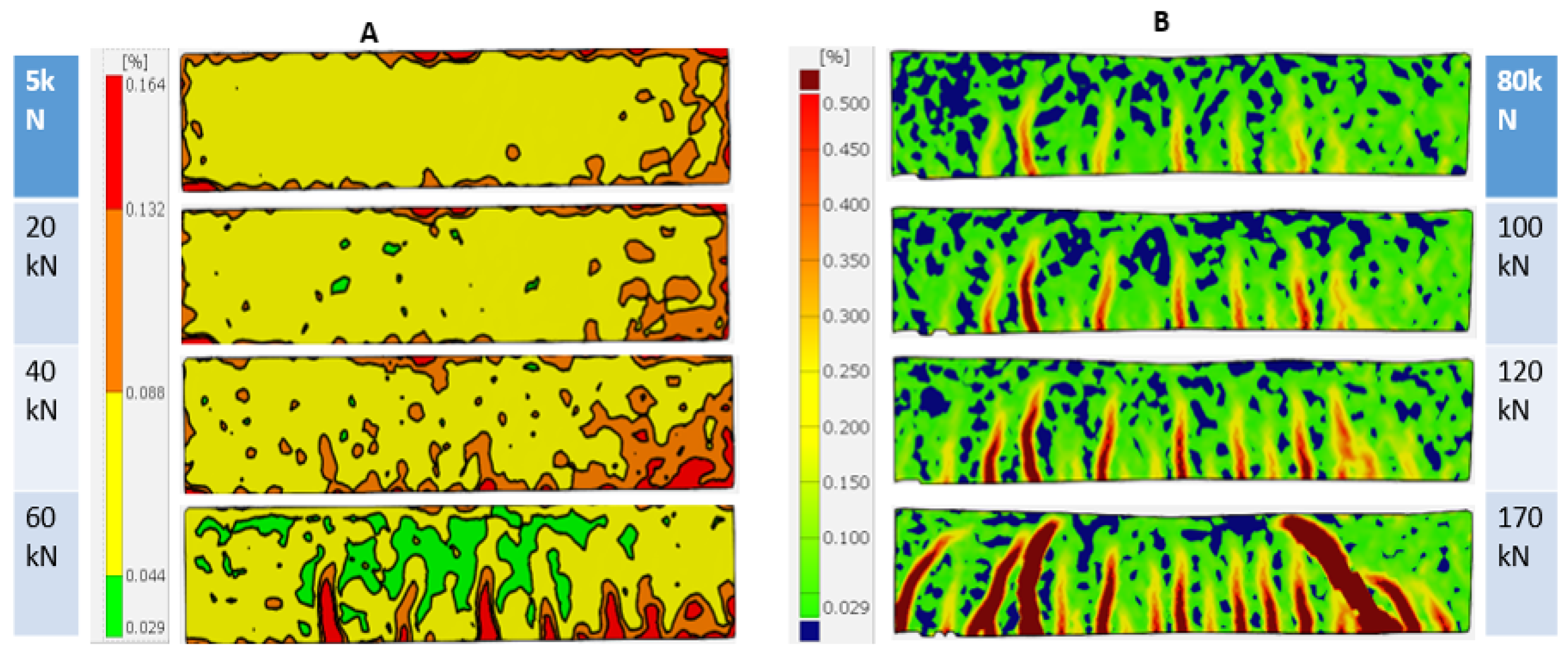
4.4. Digital Image Correlation

This result can be verified using another NDT (DIC) technique applied during the test. One can see from Figure 12 that the strain level increased in the benchmark RC beam during 0–50 kN of loading, and circulated through the most of the region and stress became noticeable, as is noted by the red colour. The first small crack could be recognised at 40 kN. Then, one propagating crack together with multiple cracks (Figure 12) was noticeable. The first small crack at 42 kN is comparable with the results from our fusion methodology. At 42 kN, the surface of the benchmark structure was examined with the naked eye, but the cracks were not visible.
However, from the analysis of DIC results, the propagation of deformation is noticeable toward the direction of load. At 52 kN, cracks forming became observable by the naked eye. However, in the second stage (80–170 kN), the results of the DIC indicate crack propagation, and the formation of new cracks through different parts of the specimen (see Figure 12B) were not visible. Some of the cracks were not visible by the naked eye during the test. At 120 kN, all the cracks were visible, correlating well with the fused coefficient index.

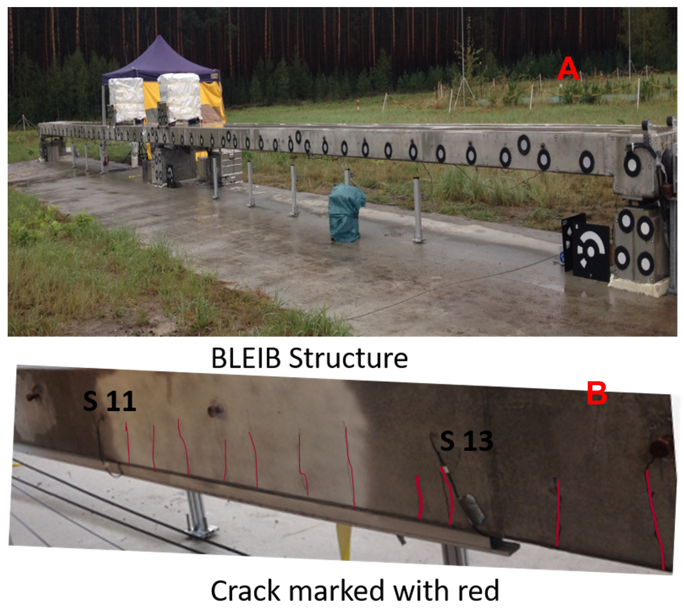
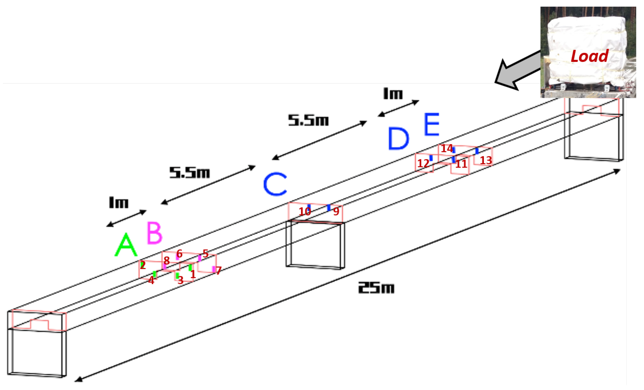
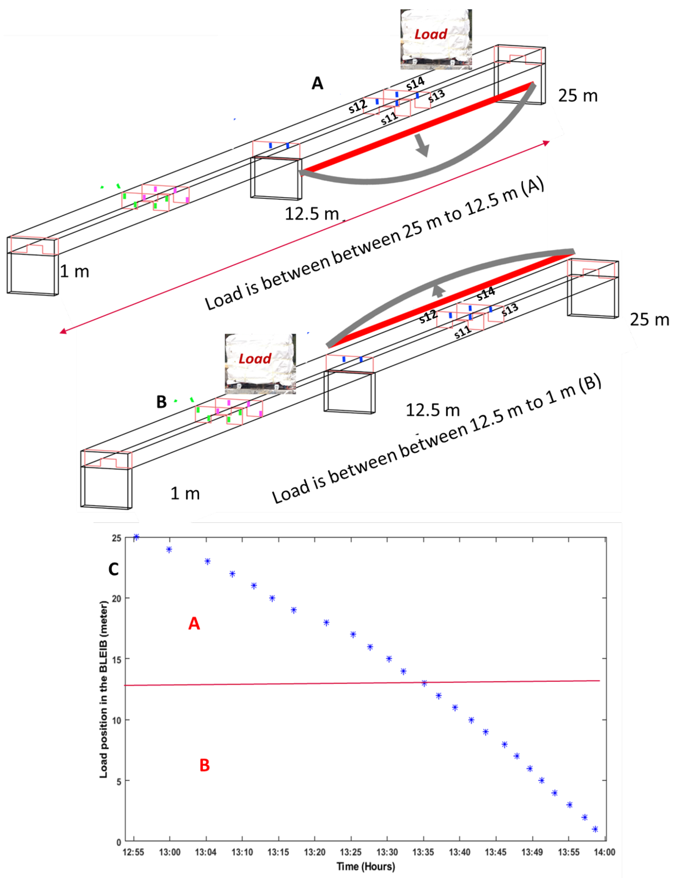
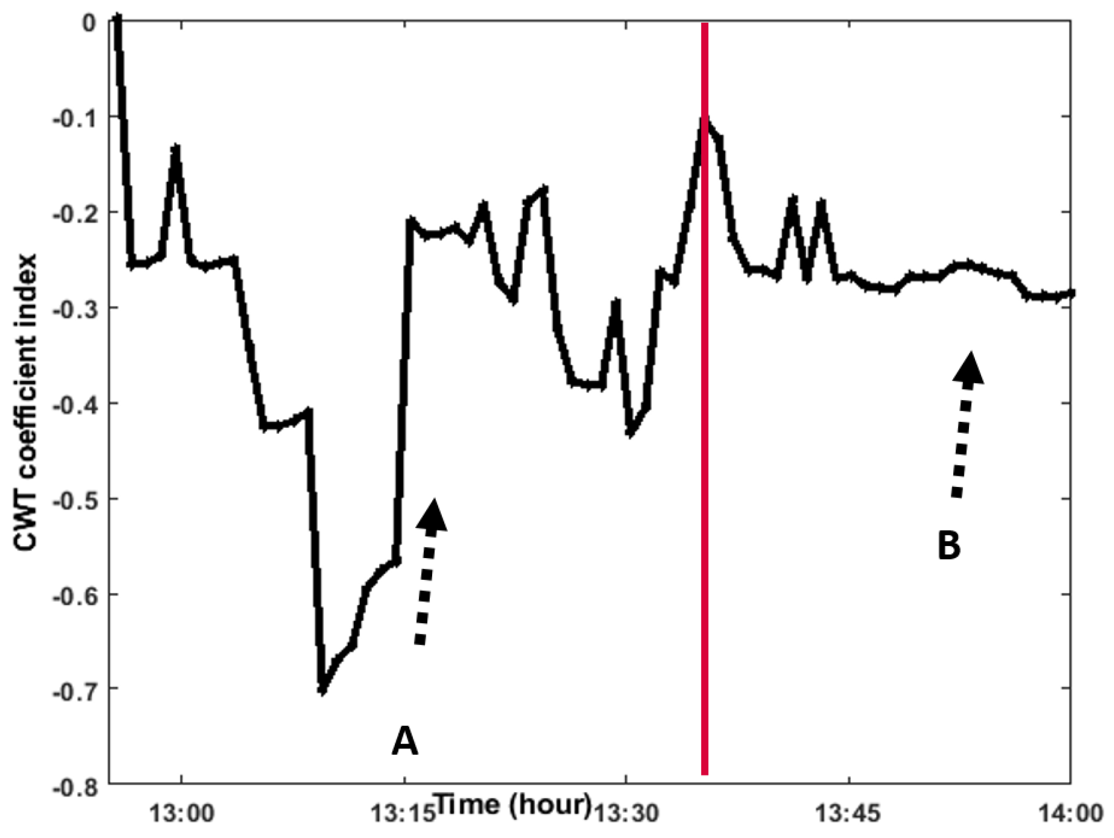
5. Full Scale Experiment

The purpose of the field test was to reveal the sensitivity of the presented fusion methodology to detect internal changes in the reference real structure (tensile and compressive stresses). The primary experimental object (BLEIB) was located in Horstwalde, Berlin, which allows us to demonstrate the real bridge, and reveal the sensitivity of our fusion methodology considering all the influences of a real structure [5,42]. The BLEIB object is a 25 m-long continuous beam (see Figure 13A). There are two cross sections. It was selected to detect the changes in real structure due to high static and dynamic loads. The embedded sensors (ultrasonic) were installed in both of the cross sections of this object during the erection period. The location of the sensors is marked in Figure 14. In this reference structure, a control crack was created to produce certain moderated damage in one of the beam. Therefore, during the load test, most of the cracks became noticeable between sensors no. 11–13, marked with a marker pen in Figure 13B. However, if the structure is reloaded, then all the cracks became closed.
A total of 14 embedded ultrasonic transducers were used for active monitoring, and controlled by an external BAM data acquisition system. This data acquisition system controlled the active monitoring through the transmission pulse, acquired signal, and repetitive duration successively to the selected transducers. Furthermore, it stored the acquiring signals to the local storage system, e.g., pairs 1 and 2, where sensor 1 transmits the pulse and sensor 2 receives the response, and stores these signals to the local disk.
The aim of installing the sensors in this reference structure is to detect similar types of changes in the bridge due to quasistatic load. To assess the changes in this reference structure, a test load was performed. Four tons of load was used as a quasistatic load during the test (Figure 15). The load was slowly moved from one side, A, to another side of the structure, B. Therefore, the temporal change of the elastic parameters or microcracking in the influence area of structure could be detected.

Change/Crack Detection

In order to illustrate the effectiveness of the fusion methodology described above, CWT features are computed from the time-domain signals collected from two pairs of ultrasonic sensors located on cross section A in the BLEIB structure during the quasistatic load experiment depicted in Figure 15. Cross section A was chosen due to location of control cracks in one of the beams (near to sensor S11-R13). However, the increase of ultrasonic wave velocity and attenuation is an indicator of initiating cracks, and can be considered as damage index [43,44,45]. Therefore, the interpretation of the CWT feature was compared with the reference signal, and if there were no operational effects in the structure, then the coefficient of the feature remains low; however, a sudden decrease of coefficient during different loading stages due to attenuation of the signal is considered as a crack opening.
During the loading stage, a quasistatic load (39.85 kN) was slowly driven ( 12 : 55 t 14 : 00 ) in several positions of the structure (schedule of the quasi-static loads and positions in the structure are shown in Figure 15). The load was driven from the edge of the structure (edge means where we marked 25 m). It can be observed that CWT features from both pairs of the sensors located in the structure performed well in their ability to detect the load. From sensor pair S11-R13, one can observe the coefficient changes due to load moving toward the sensor position and even when the load is in cross section B (see Figure 16). The CWT coefficient from sensor pairs S12-R14 (see Figure 17) increased up to a highest value in cross section A, when the load moved to top of the sensor pair. On the other hand, the CWT coefficient suddenly drops when the load comes near to the sensor pair (sensor pair S11-R13). The energy of the signal drops due to attenuation of the recorded signals. Therefore, anomalies are detected that indicate a crack opening. However, when the load driven to cross section B, the coefficient is still lower compared to sensor pair S12-R14 due to location of the cracks.
One can observe the results from both pairs of sensors. The evaluation from a single pair of sensors is not comprehensive, as pair S12-S13 do not indicate any signature of cracks, and S11-R13 show the crack opening but the coefficient does not increase even when the crack is closed. Therefore, it can be useful to use the proposed fusion methodology detailed in Section 2.1 to obtain a comprehensive result. The signal from both pairs of sensors is fused using fusion rules indicated in Figure 2. To evaluate the fused signals, CWT feature is computed from the same time histories. One can make three observations from Figure 18: the coefficient increases (load moves towards the sensors); then suddenly drops (load is on top of both sensor pairs) where the crack is visible; and the coefficient increases when the cracks are closed (specially load in cross-section B). From the CWT coefficient, one can observe the changes due to the tension and compression of the structure.

6. Conclusions

In this paper, the application of fusion methodology to combine ultrasonic signals and extract damage-sensitive features for the inspection of a reinforced concrete structure has been presented. A novel sensor fusion approach was presented to improve damage detection capability based on NDWT. The ability of the sensor fusion to detect cracks in the tested structure was verified.
The obtained experimental results from both structures show that the sensor fusion has the capability of early damage detection, and the performance is better compared to single pairs of the sensors. The SNR and damage-detection interpretation increased and verified through the ROC curve. The experiment also shows that a fusion algorithm can be beneficial to damage/change detection in a real structure. This methodology can be used in the SHM system due to its simple computation and capacity to reduce noise. The proposed fusion methodology can be applied in long-term monitoring systems.
Although features extracted from single pair of the sensors provide suitable detection results, they are not an optimal approach for the quantifying of structural damage due to the different influences in the real structure. Therefore, a large-scale bridge structure will be tested to verify the presented fusion methodology. The influence of sensor fusion for a long-term SHM system will be investigated. In addition, data from more than two transducer pairs located in the same area will be investigated to study the boundaries of signal-level fusion.

Author Contributions

All the authors conceived and designed the experiments; J.C. performed NDT experiments, the ultrasonic measurements, signal analysis, algorithms and correlation studies, and prepared the full version of the manuscript; M.S. also participated in preparation of test specimens, suggested the composition of this paper, and supervised the overall process. All authors have read and agreed to the published version of the manuscript.

Funding

Open Access funding is enabled by vouchers of MDPI. The project INFRASTAR (http://infrastar.eu/) has received funding from European Union Horizon 2020 research and Innovation Program under the Marie Curie–Skłodowska grant agreement number 676139. The grant gratefully acknowledged.

Institutional Review Board Statement

Not applicable.

Informed Consent Statement

Not applicable.

Data Availability Statement

Not applicable.

Acknowledgments

The authors wish to acknowledge the help of Ernst Niederleithinger, Xin Wang, BAM, for the sensors, data acquisition setup, and Tomasz Hahn from the Silesian University of Technology and Piotr Klikowicz from the NeoStrain Sp. z o.o., respectively, for helping with the data acquisition setup and experiment in the lab. We thank Andrzej Katunin for his technical suggestions and correction.

Conflicts of Interest

The authors declare no conflict of interest.

References

  1. Sun, M.; Staszewski, W.J.; Swamy, R.N. Smart Sensing Technologies for Structural Health Monitoring of Civil Engineering Structures. Adv. Civ. Eng. 2010, 2010, 724962. [Google Scholar] [CrossRef] [Green Version]
  2. Malhotra, V.; Carino, N.J. (Eds.) Handbook on Nondestructive Testing of Concrete; CRC Press: West Conshohocken, PA, USA, 2003. [Google Scholar]
  3. Gao, M.B.; Li, T.B.; Meng, L.B.; Ma, C.C.; Xing, H.L. Identifying crack initiation stress threshold in brittle rocks using axial strain stiffness characteristics. J. Mt. Sci. 2018, 15, 1371–1382. [Google Scholar] [CrossRef]
  4. Khadour, A.; Waeytens, J. Monitoring of concrete structures with optical fiber sensors. In Eco-Efficient Repair and Rehabilitation of Concrete Infrastructures; Woodhead Publishing: Sawston, UK, 2018; pp. 97–121. [Google Scholar] [CrossRef]
  5. Chakraborty, J.; Wang, X.; Stolinski, M. Analysis of Sensitivity of Distance between Embedded Ultrasonic Sensors and Signal Processing on Damage Detectability in Concrete Structures. Acoustics 2022, 4, 89–110. [Google Scholar] [CrossRef]
  6. Breysse, D.; Martínez-Fernández, J.L. Assessing concrete strength with rebound hammer: Review of key issues and ideas for more reliable conclusions. Mater. Struct. 2014, 47, 1589–1604. [Google Scholar] [CrossRef]
  7. Nair, A.; Cai, C.S. Acoustic emission monitoring of bridges: Review and case studies. Eng. Struct. 2010, 32, 1704–1714. [Google Scholar] [CrossRef]
  8. Hussain, A.; Akhtar, S. Review of Non-Destructive Tests for Evaluation of Historic Masonry and Concrete Structures. Arab. J. Sci. Eng. 2017, 42, 925–940. [Google Scholar] [CrossRef]
  9. Marcantonio, V.; Monarca, D.; Colantoni, A.; Cecchini, M. Ultrasonic waves for materials evaluation in fatigue, thermal and corrosion damage: A review. Mech. Syst. Signal Process. 2019, 120, 32–42. [Google Scholar] [CrossRef]
  10. Krautkraamer, J.; Krautkraamer, H. Ultrasonic Testing of Materials; Springer: Berlin/Heidelberg, Germany, 1990. [Google Scholar]
  11. Niederleithinger, E.; Wolf, J.; Mielentz, F.; Wiggenhauser, H.; Pirskawetz, S. Embedded Ultrasonic Transducers for Active and Passive Concrete Monitoring. Sensors 2015, 15, 9756–9772. [Google Scholar] [CrossRef] [Green Version]
  12. Wolf, J.; Pirskawetz, S.; Zang, A. Detection of crack propagation in concrete with embedded ultrasonic sensors. Eng. Fract. Mech. 2015, 146, 161–171. [Google Scholar] [CrossRef]
  13. Dumoulin, C.; Karaiskos, G.; Carette, J.; Staquet, S.; Deraemaeker, A. Monitoring of the ultrasonic P-wave velocity in early-age concrete with embedded piezoelectric transducers. Smart Mater. Struct. 2012, 21, 047001. [Google Scholar] [CrossRef]
  14. Niederleithinger, E.; Wang, X.; Herbrand, M.; Müller, M. Processing Ultrasonic Data by Coda Wave Interferometry to Monitor Load Tests of Concrete Beams. Sensors 2018, 18, 1971. [Google Scholar] [CrossRef] [PubMed] [Green Version]
  15. Wojtczak, E.; Rucka, M.; Skarżyński, Ł. Monitoring the fracture process of concrete during splitting using integrated ultrasonic coda wave interferometry, digital image correlation and X-ray micro-computed tomography. NDT E Int. 2022, 126, 102591. [Google Scholar] [CrossRef]
  16. de Vera, C.P.; Güemes, J.A. Embedded Self-Sensing Piezoelectric for Damage Detection. J. Intell. Mater. Syst. Struct. 1998, 9, 876–882. [Google Scholar] [CrossRef]
  17. Liggins, M.E.; Hall, D.L.; Llinas, J. Handbook of Multisensor Data Fusion: Theory and Practice; CRC Press: Boca Raton, FL, USA, 2017. [Google Scholar]
  18. Gros, X.E. Multisensor Data Fusion and Integration in NDT. In Applications of NDT Data Fusion; Springer: Boston, MA, USA, 2001; pp. 1–12. [Google Scholar]
  19. Arhamnamazi, S.A.; Bani Mostafa Arab, N.; Refahi Oskouei, A.; Aymerich, F. Accuracy Assessment of Ultrasonic C-scan and X-ray Radiography Methods for Impact Damage Detection in Glass Fiber Reinforced Polyester Composites. J. Appl. Comput. Mech. 2019, 5, 258–268. [Google Scholar]
  20. Song, Y.W.; Udpa, S. A new morphological algorithm for fusing ultrasonic and eddy current images. In Proceedings of the 1996 IEEE Ultrasonics Symposium, San Antonio, TX, USA, 3–6 November 1996; pp. 649–652. [Google Scholar]
  21. Mendoza, F.; Lu, R.; Cen, H. Comparison and fusion of four nondestructive sensors for predicting apple fruit firmness and soluble solids content. Postharvest Biol. Technol. 2012, 73, 89–98. [Google Scholar] [CrossRef]
  22. Gros, X.; Liu, Z.; Tsukada, K.; Hanasaki, K. Experimenting with pixel-level NDT data fusion techniques. IEEE Trans. Instrum. Meas. 2000, 49, 1083–1090. [Google Scholar] [CrossRef]
  23. Abidin, I.; Umar, M.; Yusof, M. Advantages and Applications of Eddy Current Thermography Testing for Comprehensive and Reliable Defect Assessment. In Proceedings of the 18th World Conference on Nondestructive Testing, Durban, South Africa, 16–20 April 2012. [Google Scholar]
  24. Khaleghi, B.; Khamis, A.; Karray, F.O.; Razavi, S.N. Multisensor data fusion: A review of the state-of-the-art. Inf. Fusion 2013, 14, 28–44. [Google Scholar] [CrossRef]
  25. Gan, Q.; Harris, C. Comparison of two measurement fusion methods for Kalman-filter-based multisensor data fusion. IEEE Trans. Aerosp. Electron. Syst. 2001, 37, 273–279. [Google Scholar] [CrossRef] [Green Version]
  26. Zhan, H.; Jiang, H.; Jiang, R. Three-dimensional images generated from diffuse ultrasound wave: Detections of multiple cracks in concrete structures. Struct. Health Monit. 2019, 19, 12–25. [Google Scholar] [CrossRef]
  27. Chakraborty, J.; Katunin, A.; Salamak, M.; Klikowicz, P.; Stolinski, M. Damage Detection in Four Point Bending Test on Benchmark RC Structure Using Feature based Fusion. Procedia Struct. Integr. 2020, 25, 324–333. [Google Scholar] [CrossRef]
  28. Choi, M. A new intensity-hue-saturation fusion approach to image fusion with a tradeoff parameter. IEEE Trans. Geosci. Remote Sens. 2006, 44, 1672–1682. [Google Scholar] [CrossRef] [Green Version]
  29. Abdel-Qader, I.; Pashaie-Rad, S.; Abudayyeh, O.; Yehia, S. PCA-Based algorithm for unsupervised bridge crack detection. Adv. Eng. Softw. 2006, 37, 771–778. [Google Scholar] [CrossRef]
  30. Alfalou, A.; Brosseau, C.; Abdallah, N.; Jridi, M. Simultaneous fusion, compression, and encryption of multiple images. Opt. Express 2011, 19, 24023. [Google Scholar] [CrossRef] [Green Version]
  31. Knitter-Piatkowska, A.; Guminiak, M.J.; Przychodzki, M. Application of Discrete Wavelet Transformation to Defect Detection in Truss Structures with Rigidly Connected Bars. Eng. Trans. 2016, 64, 157–170. [Google Scholar]
  32. Unaldi, N.; Asari, V.K. Undecimated Wavelet Transform-Based Image Interpolation; Springer: Berlin/Heidelberg, Gremany, 2010; pp. 474–483. [Google Scholar]
  33. Ellmauthaler, A.; Pagliari, C.L.; da Silva, E.A.B. Multiscale Image Fusion Using the Undecimated Wavelet Transform with Spectral Factorization and Nonorthogonal Filter Banks. IEEE Trans. Image Process. 2013, 22, 1005–1017. [Google Scholar] [CrossRef]
  34. Katunin, A. Diagnostics of Composite Structures Using Wavelets; The Publishing House of the Institute for Sustainable Technologies—National Research Institute: Gliwice, Poland, 2015. [Google Scholar]
  35. Katunin, A. Damage identification based on stationary wavelet transform of modal data. Modelowanie Inżynierskie 2014, 20, 35–41. [Google Scholar]
  36. Chakraborty, J.; Stoliński, M.; Katunin, A. Addressing the detection capability for scalable energy consumption using primary data acquisition system of embedded ultrasonic sensors in SHM. In Proceedings of the 5th International Conference on Advances in Electrical Engineering (ICAEE), Dhaka, Bangladesh, 26–28 September 2019; IEEE: Piscataway, NJ, USA, 2019. [Google Scholar]
  37. Berriman, J.; Hutchins, D.; Neild, A.; Gan, T.; Purnell, P. The application of time-frequency analysis to the air-coupled ultrasonic testing of concrete. IEEE Trans. Ultrason. Ferroelectr. Freq. Control 2006, 53, 768–776. [Google Scholar] [CrossRef] [PubMed]
  38. Chakraborty, J.; Wang, X.; Stolinski, M. Damage Detection in Multiple RC Structures Based on Embedded Ultrasonic Sensors and Wavelet Transform. Buildings 2021, 11, 56. [Google Scholar] [CrossRef]
  39. Fröjd, P.; Ulriksen, P. Frequency selection for coda wave interferometry in concrete structures. Ultrasonics 2017, 80, 1–8. [Google Scholar] [CrossRef]
  40. Chakraborty, J.; Katunin, A.; Klikowicz, P.; Salamak, M. Early Crack Detection of Reinforced Concrete Structure Using Embedded Sensors. Sensors 2019, 19, 3879. [Google Scholar] [CrossRef] [Green Version]
  41. Metz, C.E. Receiver Operating Characteristic Analysis: A Tool for the Quantitative Evaluation of Observer Performance and Imaging Systems. J. Am. Coll. Radiol. 2019, 3, 413–422. [Google Scholar] [CrossRef] [PubMed]
  42. Wang, X.; Niederleithinger, E. Coda Wave Interferometry used to detect loads and cracks in a concrete structure under field conditions. In Proceedings of the 9th European Workshop on Structural Health Monitoring Series, Manchester, UK, 10–13 July 2018; pp. 10–13. [Google Scholar]
  43. Zhang, Y.; Abraham, O.; Grondin, F.; Loukili, A.; Tournat, V.; Duff, A.L.; Lascoup, B.; Durand, O. Study of stress-induced velocity variation in concrete under direct tensile force and monitoring of the damage level by using thermally-compensated Coda Wave Interferometry. Ultrasonics 2012, 52, 1038–1045. [Google Scholar] [CrossRef] [PubMed] [Green Version]
  44. Zhang, Y.; Abraham, O.; Larose, E.; Planes, T.; Duff, A.L.; Lascoup, B.; Tournat, V.; Guerjouma, R.E.; Cottineau, L.M.; Durand, O.; et al. Following stress level modification of real size concrete structures with coda wave interferometry (CWI). AIP Conf. Proc. 2011, 1335, 1291–1298. [Google Scholar]
  45. Stähler, S.C.; Sens-Schönfelder, C.; Niederleithinger, E. Monitoring stress changes in a concrete bridge with coda wave interferometry. J. Acoust. Soc. Am. 2011, 129, 1945–1952. [Google Scholar] [CrossRef] [PubMed] [Green Version]
Figure 1. NDWT wavelet decomposition of a signal S j .
Mathematics 10 00724 g001
Figure 2. Procedure of signal-based fusion.
Mathematics 10 00724 g002
Figure 3. Measuring stand and beam load position.
Mathematics 10 00724 g003
Figure 4. Ultrasonic sensor position.
Mathematics 10 00724 g004
Figure 5. Loading schedule and number of ultrasonic measurements vs. deflection.
Mathematics 10 00724 g005
Figure 6. Ultrasonic signals from sensor pair 01-03 for different load levels.
Mathematics 10 00724 g006
Figure 10. Values of CWT coefficient feature from fused ultrasonic signal time histories.
Mathematics 10 00724 g010
Figure 11. Overall results for signals from different pairs of sensors and fused signals.
Mathematics 10 00724 g011
Figure 12. Crack images and strain distribution for different load levels of benchmark structure, first stage (A) and second stage (B).
Mathematics 10 00724 g012
Figure 13. BLEIB structure (A) and crack images (B).
Mathematics 10 00724 g013
Figure 14. Sensor position and load direction in the structure.
Mathematics 10 00724 g014
Figure 15. Schedule of quasistatic load position in the two cross section (A) and (B) of BLEIB structure.
Mathematics 10 00724 g015
Figure 16. CWT coefficient index for S11R13.
Mathematics 10 00724 g016
Figure 17. CWT coefficient index for S12R14.
Mathematics 10 00724 g017
Figure 18. Fused coefficient index (S11R13&S12R14).
Mathematics 10 00724 g018
Table 1. Evaluation of fusion results by SNR.
SignalS01R03S02R04Fused
SNR−6.8−7.85−6.5
Publisher’s Note: MDPI stays neutral with regard to jurisdictional claims in published maps and institutional affiliations.

