Article

Algorithm for Topology Search Using Dilution of Precision Criterion in Ultra-Dense Network Positioning Service Area

by
Grigoriy Fokin
1,* and
Andrey Koucheryavy
2
1
Software Defined Radio Laboratory, The Bonch-Bruevich Saint Petersburg State University of Telecommunications, 193232 Saint Petersburg, Russia
2
Department of Telecommunication Networks and Data Transmission, The Bonch-Bruevich Saint-Petersburg State University of Telecommunications, 193232 Saint Petersburg, Russia
*
Author to whom correspondence should be addressed.
Mathematics 2023, 11(10), 2227; https://doi.org/10.3390/math11102227
Submission received: 31 March 2023 / Revised: 8 May 2023 / Accepted: 8 May 2023 / Published: 9 May 2023
(This article belongs to the Section Network Science)

Abstract

:
User equipment (UE) location estimation in emerging 5G/B5G/6G Ultra-Dense Networks (UDNs) is a breakthrough technology in future wireless info-communication ecosystems. Apart from communication aspects, network infrastructure densification promises significant improvement in UE positioning accuracy. Unlike networks of previous generations, an increased number of gNodeBs (gNBs) per unit area and/or volume in UDNs allows to perform measurements for UE positioning only with those base stations whose topologies are most suitable from the geometric point of view. Quantitative measurements of gNB topology suitability include horizontal (HDOP), vertical (VDOP), and position (PDOP) dilution of the precision (DOP) criteria on the plane, in height, and in space, respectively. In the current work, we formalize a set of methods for gNB topology search using time of arrival (TOA), time difference of arrival (TDOA), angle of arrival (AOA), and combined TOA–AOA and TDOA-AOA measurements. The background of the topology search using DOP criteria is a significantly increased number of gNBs per unit volume in UDNs. Based on a simulation, we propose a novel approach for a topology search in a positioning service area, resulting in a PDOP less than one for the Gazprom Arena with only five gNBs. The contribution of the current research includes algorithm and software for an iterative search of all possible gNB and UE locations in space, minimizing UE geometric DOP. The practical application of the algorithm is the gNB topology substantiation for the given positioning scenarios in 5G/B5G/6G UDNs.

1. Introduction

User equipment (UE) location estimation is a breakthrough technology in emerging 5G [1,2,3,4], beyond 5G (B5G), and 6G [5,6,7,8,9,10,11,12,13,14,15,16,17,18,19,20,21,22,23] Ultra-Dense Networks (UDNs) [24,25]. In [1], a review of the UE location technologies, using 5G gNodeB (gNB) infrastructure, showed meter positioning accuracy. In [2], among aspects of network geolocation, the possibility of using positioning to monitor a space saturated with biomass is indicated. Together with the possibilities of radio communication and positioning in [3], the means of sensing moving objects in relation to road safety using radio signals of 5G and B5G networks are considered. The development of this approach for ultra-dense networks with Line-of-Sight (LOS) radio links is the so-called location awareness of neighboring network devices [4] and the convergence of radio communication, sensing, and positioning technologies in 6G networks [5,6]. Unlike 2G–4G cellular networks of previous generations, an increased number of gNBs per unit area and/or volume, comprising infrastructure of 5G/B5G/6G radio access networks (RANs), allows not only UE location estimation applications, but also location-aware communication (LAC) and location-aware beamforming (LAB) [26,27,28,29], becoming practically realizable not only in gNBs, but also in UE with transition to millimeter wave (mmWave).
The use of mmWave (30 GHz–300 GHz) in 5G New Radio (NR) networks and the sub-millimeter or terahertz range (0.3–3 THz) in B5G and 6G networks, due to the physical characteristics of radio wave propagation, inevitably leads to a reduction in the radio communication range and the use of predominantly LOS radio links. From the point of view of the network architecture, this circumstance entails an increase in the density of the spatial arrangement of devices, which, in turn, leads to the emergence of new tasks for the network organization at the physical, channel, and network levels of the Open Systems Interconnection (OSI) model. One of the approaches of the spatial arrangement of the infrastructure of stationary network devices, acting as a base station or gNB, access point, and/or repeater/router, can be the horizontal (HDOP), vertical (VDOP), and position (PDOP) Geometric Dilution of Precision (GDOP) criteria, well known in classical radar, radio navigation, and Global Navigation Satellite Systems (GNSSs) [30,31,32].
To date, from the analysis of open foreign sources [33,34,35], it can be argued that this approach has already become widespread in the tasks of finding and justifying the locations of base stations of 5G/B5G/6G communication networks. This is due to the new role of positioning not only as a service of communication networks, but also as an auxiliary means of solving the problems of network organization at the three lower OSI levels. In connection with the ongoing convergence of info-communication and positioning services, provided by the infrastructure of the communication networks of the 5G/B5G/6G networks [5,6,7,8,9,10,11,12,13,14,15,16,17,18,19,20,21,22,23], there is reason to believe that the approach of the gNB topology search, based on DOP criteria, deserves attention and can be used for networks of the mmWave and terahertz range, where the density of gNB and UE transceivers will exceed one device per square meter.
An analysis of open foreign sources makes it possible to point out network positioning technologies as a tool for solving problems of network organization in general [5,6,7,8,9,10,11,12,13,14,15,16,17,18,19,20,21,22,23], as well as for finding UE locations in particular. According to 3GPP specifications [36,37,38,39,40], the positioning service area should provide sub-meter 3D UE location estimation both in the horizontal and vertical planes; thus, DOP criteria minimization is of great importance.
Service requirements in 3GPP TS 22.261 [37] aim to support sub-meter location estimation accuracy in the so-called enhanced positioning service area that may be represented, for example, by a factory plant, a dense urban area, an area along a road, or a railway track. The 3GPP TR 22.872 [38] defines a typically enhanced positioning coverage area of 500 m long, 500 m wide, and 30 m high. Precise UE positioning is specified in 3GPP TS 38.305 [39] and 3GPP TR 38.855 [40], using time of arrival (TOA), time difference of arrival (TDOA), angle of arrival (AOA), and combined measurements in uplink (UL) or downlink (DL) channels.
Motivated by the described state-of-art, this work aims to develop algorithms for the gNB topology search using the dilution of precision criterion in the UDN UE positioning service area.
The paper is organized in the following order: Section 2 is devoted to background for the positioning and dilution of precision in UDNs. Section 3 describes the methods for topology search using DOP criteria and includes mathematical formalizations of the calculation procedures for the gNB topology search in space according to DOP criteria in the UE positioning service area. Section 4 presents the models and simulation results for the topology search using DOP criteria for the Gazprom Arena [41] scenario with four gNBs, using TOA, TDOA, AOA, and combined TOA–AOA and TDOA–AOA measurements. In Section 5, we propose and formalize a novel algorithm for topology search using DOP criteria. Section 6 describes the simulation results of the topology search for the Gazprom Arena scenario with five, six, and seven gNBs, using combined TOA–AOA measurements. Finally, the paper is concluded in Section 7.

2. Background for Positioning and Dilution of Precision in Ultra-Dense Networks

2.1. Ultra-Dense Network Positioning Service Area Scenario

Known investigations about the base station arrangements for the UE location estimation in radio access networks (RANs), employing the GDOP criterion, yield some valuable analytical results; however, they have a drawback regarding the assumption about two-dimensional (2D) gNBs and UE distribution according to the regular hexagonal grid, square lattice, or Poisson point process (PPP) on the plane [33,34,35]. In [33], an approach to optimize gNB locations according to the GDOP criterion of the positioning of UE on the plane is presented. In [34], the authors continue to study the issues of gNB placement to improve the accuracy of UE positioning with an increase in their density, modeled by a Poisson point process on the plane. For previous 2G–4G terrestrial cellular networks, it is justified; however, for 5G/B5G/6G UDNs, these assumptions no longer hold, and we should account for three-dimensional (3D) gNBs and UE distribution in space. Despite the fact that a gNB density increase promises positioning accuracy growth for both range and bearing estimates, employing TOA and AOA primary measurements, respectively, the problem of gNB network geometry, or positioning system topology search and its substantiation, remains relevant [42,43].
Practical applications of topology searches in UDNs can be illustrated by the UDN positioning service area example [44] employed for vehicle positioning [45,46,47]. According to 3GPP TS 22.261 [37], the enhanced positioning service area is a subset of the positioning service area with additional gNBs to increase UE location accuracy.
Figure 1 shows an example of a dense urban scenario with a road for vehicle positioning [44]. gNB topology in Figure 1 represents an example of a dense urban case and considers several stages; each stage adds a certain number of gNBs to the resulting topology for UE positioning [44]: (1) In the first stage, gNBs are located at a height of 8 m on the street lamps and are indicated by green; (2) in the second stage, gNBs are located on another street lamps at the same height of 8 m and are indicated by blue; (3) in the third stage, gNBs are located on the buildings at a height of 15 m and are indicated by yellow; (4) in the fourth stage, gNBs are located on the buildings and advertising poles at two heights, 30 m and 7.5 m, respectively, and are indicated by red.
The simulation results, performed for the scenario in Figure 1, revealed [44] that with the primary TDOA and AOA measurement errors, 50 ns and 2°, respectively, the UE positioning error on the road, defined by Cramer–Rao Lower Bound (CRLB), decreases from 4.1 m in the case of 8 gNBs in the first stage to 2.5 m in the case of 22 gNBs in the last stage. Furthermore, it was concluded that increasing the gNB number at the same height does not significantly reduce the CRLB. At the same time, it was shown that using more spatially separated gNBs at different heights reduces the CRLB for all the primary measurement processing.
The described scenario substantiates the fact that despite gNB densification, the task of UE positioning with high accuracy strongly depends on gNB topology, especially for the 3D location case. From the point of view of coordinate estimation, the ultra-dense placement of base stations allows to use for UE positioning only those gNBs, the geometrical dilution precision factor of which is most suitable for a given method of TOA [48] and/or AOA [49] measurement processing; those gNBs that are not favorable according to the GDOP criterion can be excluded [50].
Prerequisites of the gNB topology search for the UE positioning service area can be formulated in the following way [43]: Infrastructure densification in evolving 5G/B5G/6G UDNs leads to gNB redundancy, when using all of them for UE location estimation in a given positioning service area. Excess gNBs involved in positioning procedures may have counterproductive effects and lead to a huge signaling exchange in control (CP) and/or user (UP) planes, thus causing network overhead and making location estimation time- and resource-consuming, which, according to 3GPP TS 22.104 [33], is critical for a large amount of mobile UE in cyber–physical control applications in vertical domains.
To elaborate on the contribution and distinction of the proposed solution to our prior works and the works of other authors, the next sub-section gives a background and an overview of the observed problem as well as the state of the art in the field.

2.2. Topology Search Using Dilution of Precision Criterion Background

Investigation [50] demonstrates that the use of joint TDOA and AOA gives a significant improvement in the position accuracy, thanks to the use of antenna arrays and the selective gNB exclusion method that can detect and eliminate measurements affected by Non-Line of Sight (NLOS). The simulation results reveal that HDOP below 1, in terms of Cumulative Distribution Function (CDF), is attainable with a probability 0.7 for TDOA, AOA, and combined TDOA–AOA measurement processing. The drawback of the simulation approach is an assumption on the hexagonal grid for gNB deployment.
Work [51] evaluates 5G Transmission and Reception Point (TRP) standard, edge, and mixed deployment strategies for 3GPP Indoor Open Office (IOO) and Indoor Factory (InF) scenarios with downlink TDOA positioning. In particular, the work analyzes the effect of TRP densification on UE location accuracy, using a simulation with two performance metrics: GDOP contour plots and Root-Mean-Square Error (RMSE) Cramer–Rao Lower Bound. The simulation results reveals that edge TRP deployment yields higher positioning accuracy compared to standard deployment; it also confirms the obvious trend that TRP densification improves positioning accuracy. GDOP is computed for each point in the deployment area with a given step and depends on the TRP topology and positioning method. For the case of TDOA positioning, the GDOP can be lower than one for optimistic UE location in the geometric center of the positioning area. Despite the conclusion about paramount influence of TRP deployment geometry on UE localization accuracy, it analyzes GDOP for only pre-defined TRP positions, while the problem for the TRP topology search is out of scope. One more weak point of this analysis is that it is for 2D cases only.
Research [52] derives the GDOP factor for the proposed hybrid TDOA and TOA positionings in the 5G cellular communication system. GDOP is defined as the ratio of the accuracy limitation of a position fix to the accuracy of TOA, TDOA, or AOA primary measurements. The authors analyze the GDOP factor with four base stations in a simulation scenario according to the real scene of the underground parking lot at Beijing University of Posts and Telecommunications. The simulation results for the proposed hybrid TDOA–TOA positioning reveal a minimum GDOP of 0.59, and the minimum GDOP of the TDOA-only positioning is just 0.79, which confirms the possibility to attain ideal GDOP values lower than 1. From the point of view of the topology search in the UDN scenario, the drawback of the research in [52] is that the GDOP analysis of pre-defined gNB topology is for 2D cases only.
Investigation [53] argues that localization accuracy should play a prominent role in cellular infrastructure planning and consider GDOP as a metric, which could contribute to geometrically favorable 5G base station deployment for UE positioning. It points out the importance of GDOP, which is independent of the particular positioning methodology employed and states that even if a sophisticated positioning system is used, it can turn out to be inaccurate if positioning architecture with physically deployed base stations is not taken into account. At the same time, investigation [53] claims that understanding GDOP allows to substantiate the best base station deployment. The authors contribute to a stochastic theory of location-based Fisher information in wireless networks, concerned with how to best physically deploy gNBs in order to minimize UE GDOP and develop a closed-form probability density function (PDF) to characterize the angular difference of a pair of base stations and a UE. Then, the authors, using a produced PDF, show some gNB deployments that are guaranteed to yield a favorable GDOP for UE positioning. The problem of practical utilization of the reported results is complicated for the case of more than two gNBs; it is also only for 2D cases and is limited by the assumption of the hexagonal lattice model for gNB locations.
Work [54] proposes to select the most appropriate sub-set of four Base Stations (BSs) among the set of seven BSs. An approach is to calculate the UE locations for all BS sub-sets and to select those that give the smallest GDOP. Despite an interesting approach of selecting the best topology, the drawback of this analysis is that it is for 2D cases only and is a rather poor choice among the sub-set of seven BSs with pre-defined locations.
Research [55] points out the proliferation of AOA primary measurements for UE positioning in cellular wireless networks due to smart antenna emergence and considers DOP expressions that relate the primary measurement error to the position error through dilution of the precision factor. As an expression for AOA positioning, DOP was derived, and it demonstrated values below one even for two base stations on the plane (2D case).
The authors in [56] investigate the DOP of a positioning system, combining AOA and TOA primary measurements, and show that the DOP is related to the size of the deployment area (distance apart) and explain why the DOP quantity for the AOA system is associated with the size of the deployment area, while the DOP quantity for the TOA system is not. When the size of the deployment area scales up to infinity, the DOP is decided by the TOA part of the system, but when the deployment area size scales down to infinitely small, the DOP is decided by the AOA part of the positioning system. The drawback of the work is that it analyses the DOP values with one, two, and three different configurations of base stations only, which is weakly consistent with the 5G UDN scenario.
The Dynamic Base Station Selection (DBSS) method, proposed in [57], enables cellular systems to dynamically select the positioning base station for the UE location estimation, specifically for the case of four and five base stations. The drawback of the proposed approach is the assumption about regular hexagonal base station arrangements on the plane.
Investigation [58] performs a GDOP analysis to obtain concise analytical expressions for several scenarios, which are generally applicable to geometries where the UE is surrounded by gNBs. Despite the conclusion that the results provide useful information for the design and testing of tracking systems, as well as for the determination of the geometric deployment of base stations for a good GDOP in the coverage area, it covers only simple geometric 2D cases, for which analytical solutions are possible, and thus does not respond to scenarios of 5G and B5G UDN gNB distribution in 3D space.
Work [59] analyzes the impact of variable geometry and the number of 5G base stations on the convergence time of precise point positioning in combined BeiDou Navigation Satellite System (BDS) and 5G mobile communication technology. Despite attainable DOP values, the weak point of the investigation is that the analysis is performed on a pre-defined geometrical configuration of gNB; however, the topology search is a much more flexible tool.
Research [60] analyzes the relationship between DOP and Round-Trip Time (RTT) and angle of departure (AOD) positioning accuracy. The performed simulation experiments in two scenarios of three gNBs with good and complex environments and subsequent conclusions, again, are limited to the analysis on pre-defined geometrical configurations of gNBs.
The author in [61] examines the positioning geometric dilution of precision bounds in two-dimensional scenarios and shows that the lowest possible GDOP attainable for TOA or TDOA measurements with N optimally located base stations, reaches a value of 2 / N . The motivation behind the investigation is the assumption that the best GDOP occurs if the N base stations are at the vertices of an N -sided regular polygon and the minimum GDOP is at the center of this polygon. The simulation results for the case of 5 base stations yield the lowest contour value of approximately 0.9 at the center of this polygon, which agrees with the analytical estimate 2 / N and reaches a value below 1. Work [61] also points out an important nuance for bearing-only measurements: the matrix of partial AOA derivatives yields measurement errors in units of radians, while the position error is in units of meters. To obtain a dimensionless GDOP, the author in [61] defines a normalized GDOP by the additional multiplication of partial AOA derivatives on the gNB–UE distance.

2.3. Topology Search Using Dilution of Precision Criterion Problem Statement

The above analysis of the background and state of the art in the field of topology search, using the dilution of precision criterion in UDNs, according to open sources, revealed that most of the observed investigations were devoted to the analysis of the pre-defined base station configurations with inherent limitations of the regular hexagonal layout on the plane for 2D cases. However, the problem of gNB topology synthesis in the space for 3D cases has not even been set up. This circumstance can be explained by the fact that even for pre-defined gNB configuration obtaining HDOP, VDOP, and PDOP requires a lot of calculations, the volume of which depends on the step size for the possible UE location in space areas for 3D cases. One of the solutions for the gNB topology search is its configuration enumeration with a given DOP (HDOP, VDOP, or PDOP) criterion in the defined deployment area and the limit on available gNB numbers. The task is complicated by the fact that the obtained topology, favorable, for example, to the HDOP criterion, is not favorable to VDOP; thus, it is appropriate to perform a search according to the integral PDOP criterion.
Our own previous results [42,43] concerning a topology search using the DOP criterion for the enhanced 5G positioning service area considered the configuration of only four gNBs, which is enough for UE positioning in space with either the TOA, TDOA, or AOA method. Work [42] proposes a TOA measurement processing model for a 5G UDN positioning system topology search using HDOP, VDOP, and PDOP criteria, which revealed that the configuration of a fixed gNB number, achieving a DOP criterion in the horizontal plane, does not provide a satisfying DOP in the vertical plane. In particular, the gNB topology found for HDOP fails to meet the VDOP and PDOP in the analyzed enhanced positioning service area, because the HDOP case requires to spread gNBs from the UE on the plane, and the VDOP case requires to spread gNBs from UE on the height, being close to UE, which is contradictory. To overcome this contradiction, a further investigation [43] considers the already combined TOA and DOA measurement processing for the case of fixed UE height in the positioning service area, which yielded a gNB topology with HDOP, VDOP, and PDOP values below 2 for the whole 2D plane of the enhanced 5G positioning service area. However, the simulation results also revealed that for the case of variable UE height in a 5G positioning service area and for the case of more than four gNBs, a new topology search algorithm should be developed.
The purpose of this research is to verify models and methods for finding locations for gNBs in space, based on the geometrical dilution of the precision factor for UE positioning accuracy on the plane (HDOP), along the height (VDOP), and in space (PDOP). To achieve this goal, this paper solves the problem of formalizing the algorithms and methods and developing software for evaluating the effectiveness of gNB locations in space, based on the geometrical dilution of the precision factor for UE positioning accuracy. A simulation model performed a brute-force gNB topology search using gNB and UE grid models [42,43] and DOP criteria without prior restrictions on the gNB spatial layout for the positioning service area.

3. Methods for Topology Search Using DOP Criteria in UDNs

In the current section, we formalize the calculation of the GDOP factor for TOA, TDOA, AOA, and combined TOA–AOA and TDOA–AOA measurements and do not consider derivation of the Cramer–Rao Lower Bound, because it is well known, for example, from a range of pioneering [62,63,64,65,66,67] and contemporary [68,69,70,71,72] works, that the CRLB for the RMSE of UE positioning accuracy can be decomposed into the geometric dilution of precision, due to the topology of the base stations, and corresponding error of primary range, range difference, or angle measurements. Next, let us first formalize the methods for estimating the DOP factors of gNB placement in space at a fixed location of the UE according to our previous work [42,43].

3.1. UE and gNB 3D Layout Geometry

Figure 2 illustrates the spatial arrangement model of the UE and gNBs [42,43].
Denoted by x n = x n , y n , z n T , the column vector of the base station coordinates g N B n , where n = 1 , , N , N is the total number of base stations in a given area of space; T is the transposition operator. Let x = x , y , z T be the column vector of the UE coordinates. Assuming that all base stations are perfectly synchronized with each other and equipped with antenna arrays (AA), then all g N B n , n = 1 , , N can collect the following primary measurements from UE: (a) Time of Arrival T O A n = τ n ; (b) Time Difference of Arrival T D O A n = τ n = τ n τ 1 ; (c) AOA/DOA Angle/Direction of Arrival A O A n = φ n , θ n , including φ n —azimuth and θ n —elevation angle [42,43].
Suppose gNB coordinates are known, and mobile UE coordinates are unknown. Let the base station g N B n be located at the point with coordinates x n , then, the coordinates x of the UE can be represented by the radius vector
d n = x x n = x n , y n , z n T
directed from g N B n to the UE, where
x n = x x n ; y n = y y n ; z i = z z n .
In vector representation, the UE coordinates can be represented by
x = x n + d n .
The vector d n is directed from the point x n to the point x and characterizes the distance d n between the UE and g N B n and the direction of signal arrival from the UE to g N B n , given by the direction A O A n from the pair of azimuths φ n and elevation angle θ n . Distance d n between UE and g N B n is defined as [42,43]:
d n = d n 2 = x x n 2 = x n 2 + y n 2 + z n 2 = x x n 2 + y y n 2 + z z n 2 ;
where · 2 is the Euclidean norm of the vector.
The projection of the spatial radius vector d n onto the x y plane is given by:
d n x y = x n 2 + y n 2 = d n cos θ n .

3.2. Model for Primary Measurement Collection

Range measurement d n with TOA at the g N B n can be represented by expression:
d n = c τ n = x x n 2 ;   n = 1,2 , , N ;
where τ n is the time of arrival of the signal from the UE to g N B n ; c = 3 · 10 8   m / s is the speed of light.
Range difference measurement d n with TDOA at the base station g N B n with respect to g N B 1 can be represented by the expression:
d n = c τ n = c τ n τ 1 = x x n 2 x x 1 2
Direction of arrival measurement of azimuth AOA φ n and elevation AOA θ n at the base station g N B n can be represented by the expressions [43]:
φ n = tan 1 y n / x n = y y n x x n , n = 1,2 , , N ;
θ n = tan 1 z n / d n x y = z z n d n x y , n = 1,2 , , N .
Next, we formalized models for TOA, TDOA, AOA, joint TOA–AOA, and joint TDOA–AOA measurement processing.

3.3. Methods of Primary Measurement Processing

3.3.1. TOA Measurement Processing

Non-linear vector f T O A x and scalar f T O A , n x functional dependence, relating n = 1 , , N range measurements d n x in (6) with known g N B n coordinates x n and unknown UE coordinates x , are defined by the expressions:
f T O A x = f T O A , 1 x , , f T O A , n x T ;
f T O A , n x = d n x = x x n 2 + y y n 2 + z z n 2 .
Jacobi matrix (matrix of partial derivatives) for range measurements in three coordinates in space f T O A x = f T O A x / x R N × 3 is defined by [42]:
J T O A x = x x 1 d 1 y y 1 d 1 z z 1 d 1 x x 2 d 2 y y 2 d 2 z z 2 d 2 x x N d N y y N d N z z N d N .

3.3.2. TDOA Measurement Processing

Non-linear vector f T D O A x and scalar f T D O A , n x functional dependence, relating n = 2 , , N range difference measurements d n x in (7) with known g N B n coordinates x n and unknown UE coordinates x , are defined by expressions:
f T D O A x = f T D O A , 2 x , , f T D O A , n x T .
f T D O A , n x = d n x = x x n 2 + y y n 2 + z z n 2 x x 1 2 + y y 1 2 + z z 1 2 .
Jacobi matrix for range difference measurements in three coordinates in space J T D O A x = f T D O A x / x R N 1 × 3 is defined by [43]:
J T D O A x = x x 2 d 2 x x 1 d 1 y y 2 d 2 y y 1 d 1 z z 2 d 2 z z 1 d 1 x x 3 d 3 x x 1 d 1 y y 3 d 3 y y 1 d 1 z z 3 d 3 z z 1 d 1 x x N d N x x 1 d 1 y y N d N y y 1 d 1 z z N d N z z 1 d 1 .

3.3.3. AOA Measurement Processing

Non-linear vector functional dependence f A O A x , relating N AOA measurements of azimuth φ n in (9) and N AOA measurements of elevation angle θ n in (9) with known gNB coordinates x n and unknown UE coordinates x , is defined by expression [43]:
f A O A x = f φ x f θ x T ;
where f φ x and f θ x are non-linear vector functional expressions of dependence on azimuth and elevation, respectively.
Non-linear vector f φ x and scalar f φ , n x functional dependence, linking n = 1 , , N AOA measurements of azimuth φ n in (9) with known g N B n coordinates x n and unknown UE coordinates x , are defined by the expressions:
f φ x = f φ , 1 x , , f φ , n x T ;
f φ , n x = φ n x = tan 1 y n / x n = y y n x x n ;
Jacobi matrix for AOA measurements of azimuth angle φ n in three coordinates in space J φ x = f φ x / x R N × 3 is defined as [43]:
J φ x = y y 1 x x 1 2 + y y 1 2 x x 1 x x 1 2 + y y 1 2 0 y y 2 x x 2 2 + y y 2 2 x x 2 x x 2 2 + y y 2 2 0 y y N x x N 2 + y y N 2 x x N x x N 2 + y y N 2 0 ;
Using trigonometric relations and notions in Figure 2:
sin φ n = y n / d n x y ; cos φ n = x n / d n x y ;
expression (19) can be represented as follows [43]:
J φ x = sin φ 1 d 1 x y cos φ 1 d 1 x y 0 sin φ 2 d 2 x y cos φ 2 d 2 x y 0 sin φ N d N x y cos φ N d N x y 0 ;
When calculating the Jacobian matrices for range and range-difference measurements, the values of the derivatives are dimensionless, but for the angle measurements, the values of the derivatives have the dimension of meters in the denominator [55]; thus, to obtain dimensionless values, the partial derivatives in (21) should be additionally multiplied by d n x y in (5), then we obtain:
J φ x = sin φ 1 cos φ 1 0 sin φ 2 cos φ 2 0 sin φ N cos φ N 0 .
Non-linear vector f θ x and scalar f θ , n x functional dependence, relating n = 1 , , N AOA measurements of elevation angle θ n in (10) with known g N B n coordinates x n and unknown UE coordinates x , are defined by expressions:
f θ x = f θ , 1 x , , f θ , n x T ;
f θ , n x = θ n x = tan 1 z n / d n x y = z z n d n x y .
Jacobi matrix for AOA measurements of elevation angle θ n in three coordinates in space J θ x = f θ x / x R N × 3 is defined as [43]:
J θ x = z z 1 x x 1 d 1 2 d 1 x y z z 1 y y 1 d 1 2 d 1 x y d 1 x y d 1 2 z z 2 x x 2 d 2 2 d 2 x y z z 1 y y 2 d 2 2 d 2 x y d 2 x y d 2 2 z z N x x N d N 2 d N x y z z N y y N d N 2 d N x y d N x y d N 2 .
Using trigonometric relations and notions in Figure 2:
sin θ n = z n / d n ; cos θ n = d n x y / d n ;
expression (25) can be represented as follows [43]:
J θ x = cos φ 1 sin θ 1 d 1 sin φ 1 sin θ 1 d 1 cos θ 1 d 1 cos φ 2 sin θ 2 d 2 sin φ 2 sin θ 2 d 2 cos θ 2 d 2 cos φ N sin θ N d N sin φ N sin θ N d N cos θ N d N .
To obtain dimensionless values, the partial derivatives in (27) should be additionally multiplied by d n in (6), then we obtain:
J θ x = cos φ 1 sin θ 1 sin φ 1 sin θ 1 cos θ 1 cos φ 2 sin θ 2 sin φ 2 sin θ 2 cos θ 2 cos φ N sin θ N sin φ N sin θ N cos θ N .
The Jacobi matrix J A O A x R 2 N × 3 for AOA measurements in azimuth φ n and elevation θ n is given by:
J A O A x = J φ x J θ x T = sin φ 1 cos φ 1 0 sin φ 2 cos φ 2 0 sin φ N cos φ N 0 cos φ 1 sin θ 1 sin φ 1 sin θ 1 cos θ 1 cos φ 2 sin θ 2 sin φ 2 sin θ 2 cos θ 2 cos φ N sin θ N sin φ N sin θ N cos θ N .

3.3.4. Combined TOA–AOA and TDOA–AOA Measurement Processing

For combined range and bearing TOA–AOA measurements, Jacobian matrix is:
J T O A A O A x = J T O A x J A O A x T .
For combined TDOA–AOA measurements, Jacobi matrix is given by:
J T D O A A O A x = J T D O A x J A O A x T .
Next, consider the estimation of the geometric dilution of precision factors.

3.4. Geometric Dilution of Precision Calculation

Denote by x ^ = x ^ y ^ z ^ T the coordinate estimate of the UE, then the error covariance matrix of the UE coordinate estimate is determined by the expression [42]:
Σ = E x ^ E x ^ x ^ E x ^ T = σ x 2 σ x y σ x z σ y x σ y 2 σ y z σ z x σ z y σ z 2 .
where E · is the expectation operator, the elements on the main diagonal σ x 2 , σ y 2 , σ z 2 of the covariance matrix Σ represent the variances of the UE coordinate estimates along the x , y , and   z axes, respectively; the remaining elements of the matrix Σ are UE coordinate estimate covariances. The potential accuracy of the UE coordinate estimates is determined by the Cramer–Rao Lower Bound and is calculated from the inverse Fisher Information Matrix FIM (Fisher Information Matrix):
C R L B x ^ = t r a c e F I M 1 x ^ = t r a c e Σ .
The CRLB of UE coordinate estimates, which considers only the location of gNBs and UE in space, is determined by the elements of the main diagonal of the covariance matrix Σ , normalized by the error of primary measurements σ of the signal arrival time σ τ for TOA and TDOA measurements, or the signal arrival angle σ A O A for AOA measurements. Thus, for the TOA method, the estimate of the dimensionless geometric DOP factor is determined by the diagonal elements from the following expression:
G = Σ / c σ τ 2 = ( J T J ) 1 = G x x G x y G x z G y x G y y G y z G z x G z y G z z .
where J is the Jacobi matrix for TOA measurements (13). For TDOA, AOA, TOA–AOA, and TDOA–AOA, we should use expressions for J in (15), (29), (30), and (31), respectively.
The geometric DOP factor in space (PDOP), horizontal plane (HDOP), and vertical plane (VDOP) are determined from the following expressions [43]:
P D O P = G x x + G y y + G z z ;
H D O P = G x x + G y y ;
V D O P = G z z ;
Software implementation of computational procedures for calculating PDOP (35), HDOP (36), and VDOP (37) when placing gNBs and UE in space is available at [73].

4. Models for Topology Search Using DOP Criterion in UDNs

4.1. Spatial Parameters for Topology Search Using DOP Criterion in UDNs

To model methods for placing devices in space, we proceeded with the following parameters of the geographical extent of the UDN positioning service area. In the specification 3GPP TS 22.261 [37] for UE positioning, using the ranging method, the following categories of effective ranging distance between two pieces of UE are introduced: 1, 2, 5, 10, 20, 30, 100, 500, and 1000 m. At the same time, for some categories, requirements are established for the accuracy of both primary range and angle measurements; for example, for a long-range approximate location scenario with a UE of 500 m, the required accuracy of range and angle measurements is 10 m and 12.5°, respectively (Table 7.9.1 in [37]). The 3GPP TR 22.872 [38] defines an enhanced positioning area of 500 m by 500 m in a horizontal plane and 30 m high in a vertical plane (Table 8.2.1 in [38]).
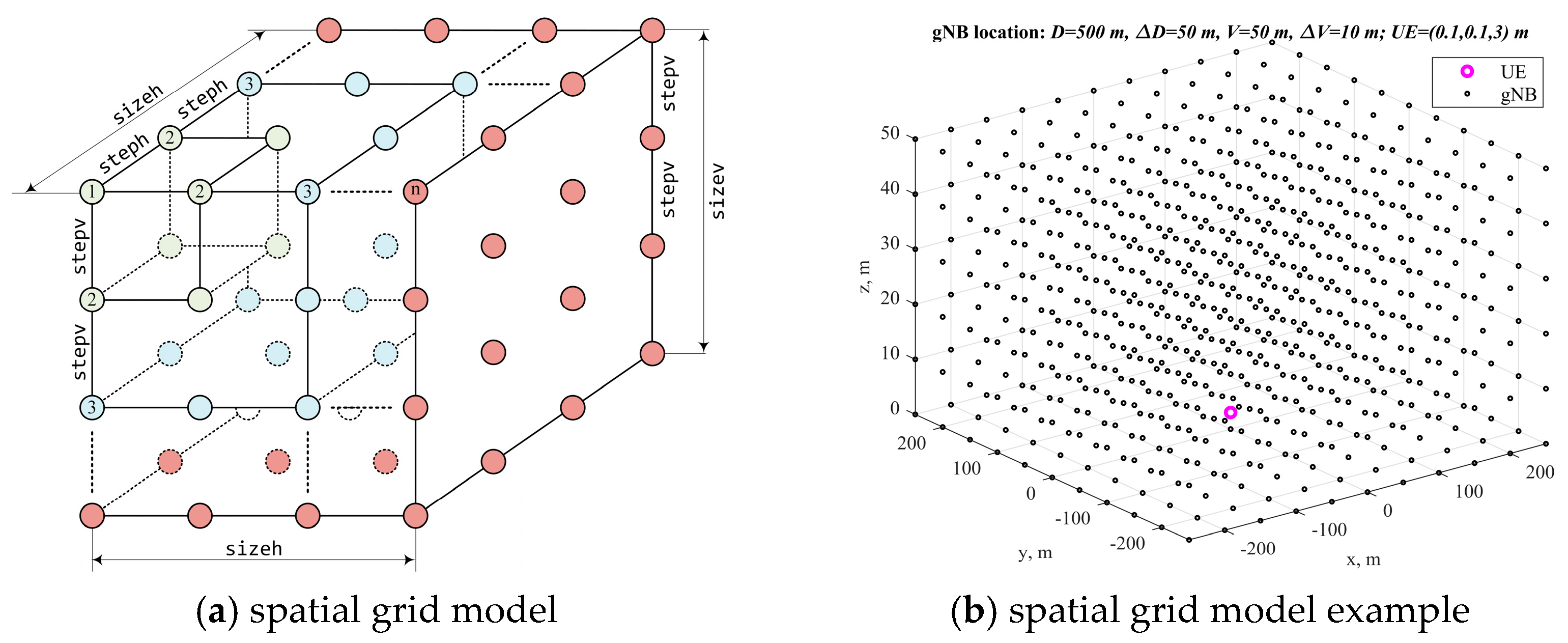
Table 1 contains parameters for the UE positioning area with placement of gNBs in space, as well as horizontal and vertical steps, which model the density of gNBs in space.
Figure 3a illustrates spatial grid model for possible gNB and UE locations according to the spatial parameters of the topology search in Table 1. To select the parameters of the device placement area, consider as an example the parameters of the Gazprom Arena stadium [41]: the roof diameter is 286 m, and the height from the ground to the roof is 75 m. Thus, the territory of the stadium fits with a margin in the size of the zone of the enhanced positioning service area with a length D = 500   m . The height parameter for the analysis of the area of placement of devices in space vertically is assumed to be V = 100   m . Figure 3b illustrates an example of a spatial grid in a space of 500 × 500 × 50 m with horizontal and vertical steps D = 50   m and V = 10   m , respectively. The UE is fixed in the center of the grid in point with coordinates x = 0.1,0.1,3 T .
Further, to search for gNB locations, the step of their possible placement in space horizontally and vertically, we will take equal-to-minimum values of the relative range for UE-relative positioning with the ranging method: D = V = 1   m [37], i.e., steph = stepv = 1.
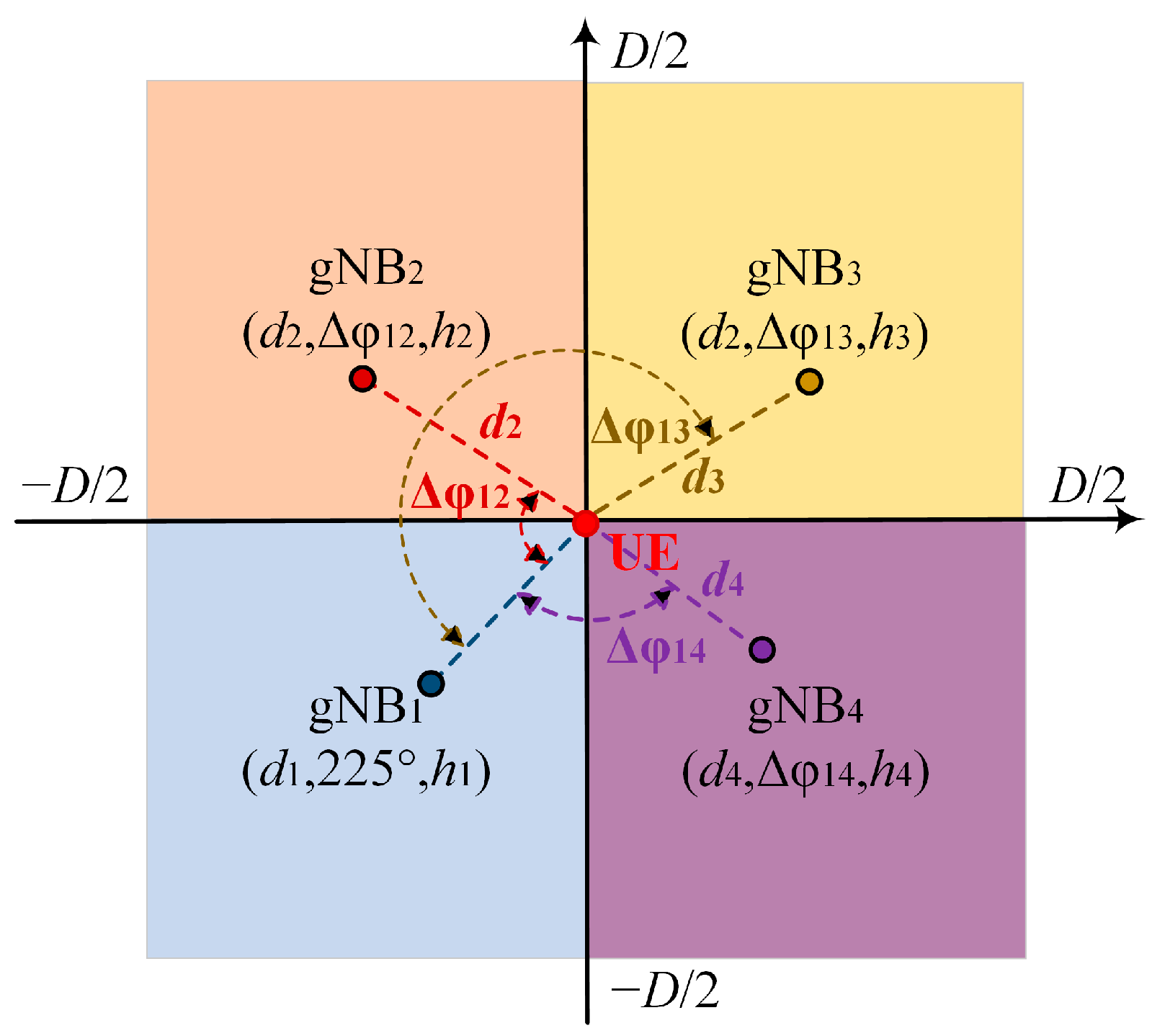
At least four gNBs are required for UE positioning in space by the range-difference method, so the present model and corresponding software implementation searches for the locations of four gNBs. All functions comprising open-source software implementation are available at https://github.com/grihafokin/Topology_search_using_DOP (accessed on 27 March 2023). Based on the premise of the uniform placement of gNBs in the UE positioning service area, in order to obtain the best DOP factor of the UE location estimation accuracy, the search for gNB locations was carried out by the brute-force method in equal quadrants of a given service area. Figure 4 shows four gNB quadrants for the topology search. A square was divided into four equal parts that were used to search for the locations of four gNBs, each of which is in its own quadrant.

4.2. Procedures for Topology Search Using DOP Criterion in UDNs

To search for gNB locations, we first initialized the number of search iterations M , an array R N × M × 1 of all possible coordinates x n = x n , y n , z n T for n = 1 , , N gNBs, as well as a vector of geometric factors PDOP, HDOP, and VDOP of dimension R M × 1 . After the initialization of arrays and vectors, the method of primary measurements was set (TOA, TDOA, AOA, TOA–AOA, and TDOA–AOA), according to which the analysis and search for gNB placements was carried out further by the DOP criterion.
Further, in the loop according to the number of search iterations M , the following procedures were performed: from a given set of quadrants in Figure 4, a random choice of coordinates for each gNB was made, and after that, with a fixed UE location x = x , y , z T and selected location of gNB set x n = x n , y n , z n T , the simulation model calculated PDOP, HDOP, and VDOP. The results of the calculation of PDOP, HDOP, and VDOP together with the gNB coordinates for each iteration were stored in previously initialized vectors and served as initial data for further processing in order to find the best gNB topology in space according to the DOP criterion. The first step in processing of the calculated PDOP, HDOP, and VDOP values was the initialization of the minimum D O P m i n and maximum D O P m a x values of the DOP factors; DOP values less than two were considered good [30,31,32]. Next, the gNB configurations were processed for only one DOP criterion.
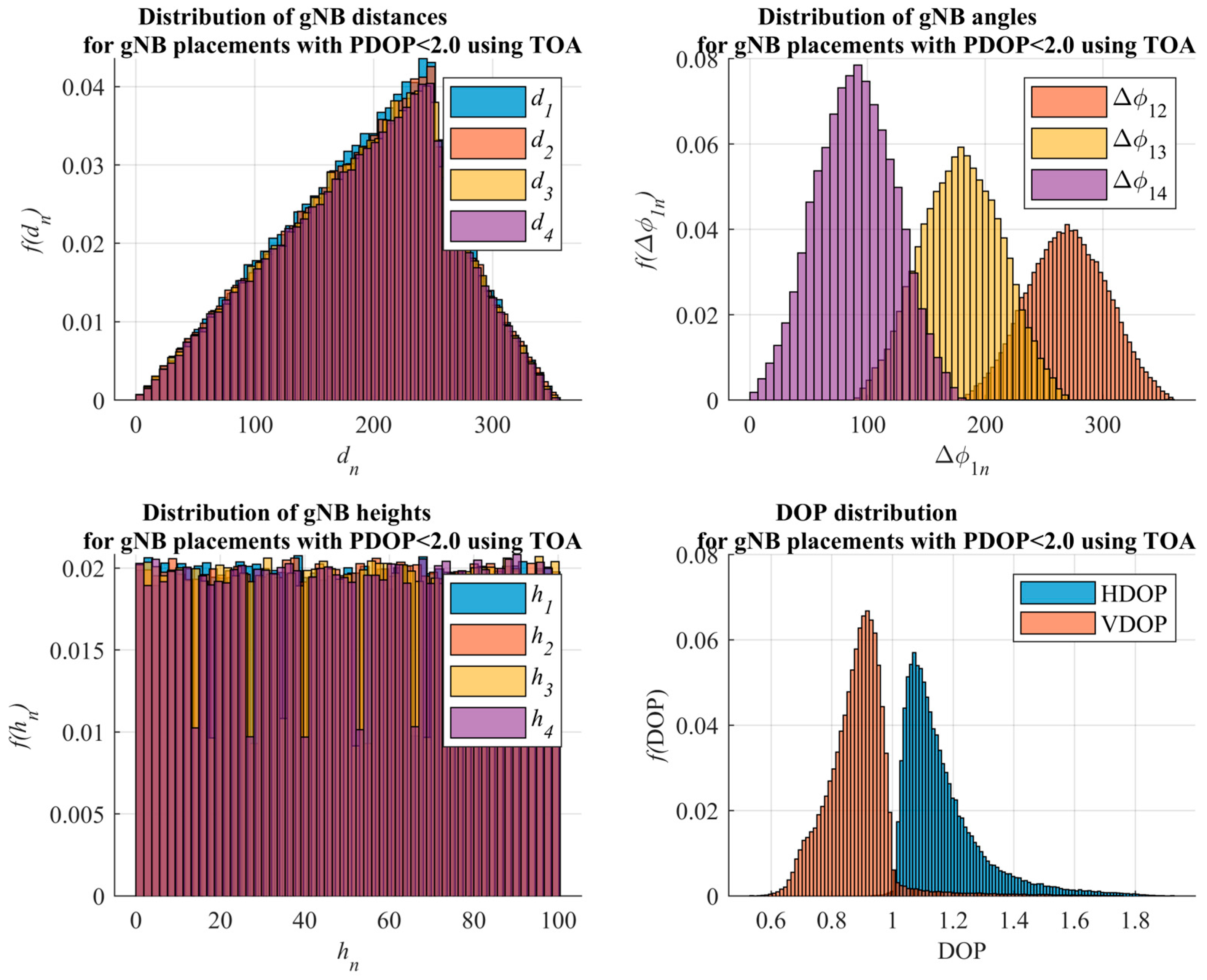
The processing began with filtering out the gNB placement configurations that met the maximum DOP factor requirements; those configurations of gNB, for which PDOP, HDOP, and VDOP exceeded the value of D O P m a x , were excluded from further analysis. After filtering the gNB configurations, they were sorted in ascending order of the DOP factors. For each gNB configuration, the distance d n and the angle φ 1 n to the UE were calculated, as well as the height h n of each base station. Based on the parameters d n , φ 1 n , and h n , their distributions were calculated, and the most probable ones were searched [42]. The resulting functions f d n , f φ 1 n , and f h n , plotted in Figure 5 for TOA measurements, are obtained distributions of g N B n distance d n , angle φ 1 n , and height h n , giving the most probable geometrical values of gNB topology, which provided DOP in a given range.
Further, according to the parameters of ranges d n , angles φ 1 n , and heights h n of four gNBs, relative to the UE, the absolute coordinates of each gNB were calculated according to
x n y n z n = cos ( φ 1 n ) sin ( φ 1 n ) 0 sin ( φ 1 n ) cos ( φ 1 n ) 0 0 0 1 d n 0 h n = d n cos ( φ 1 n ) d n sin ( φ 1 n ) h n .
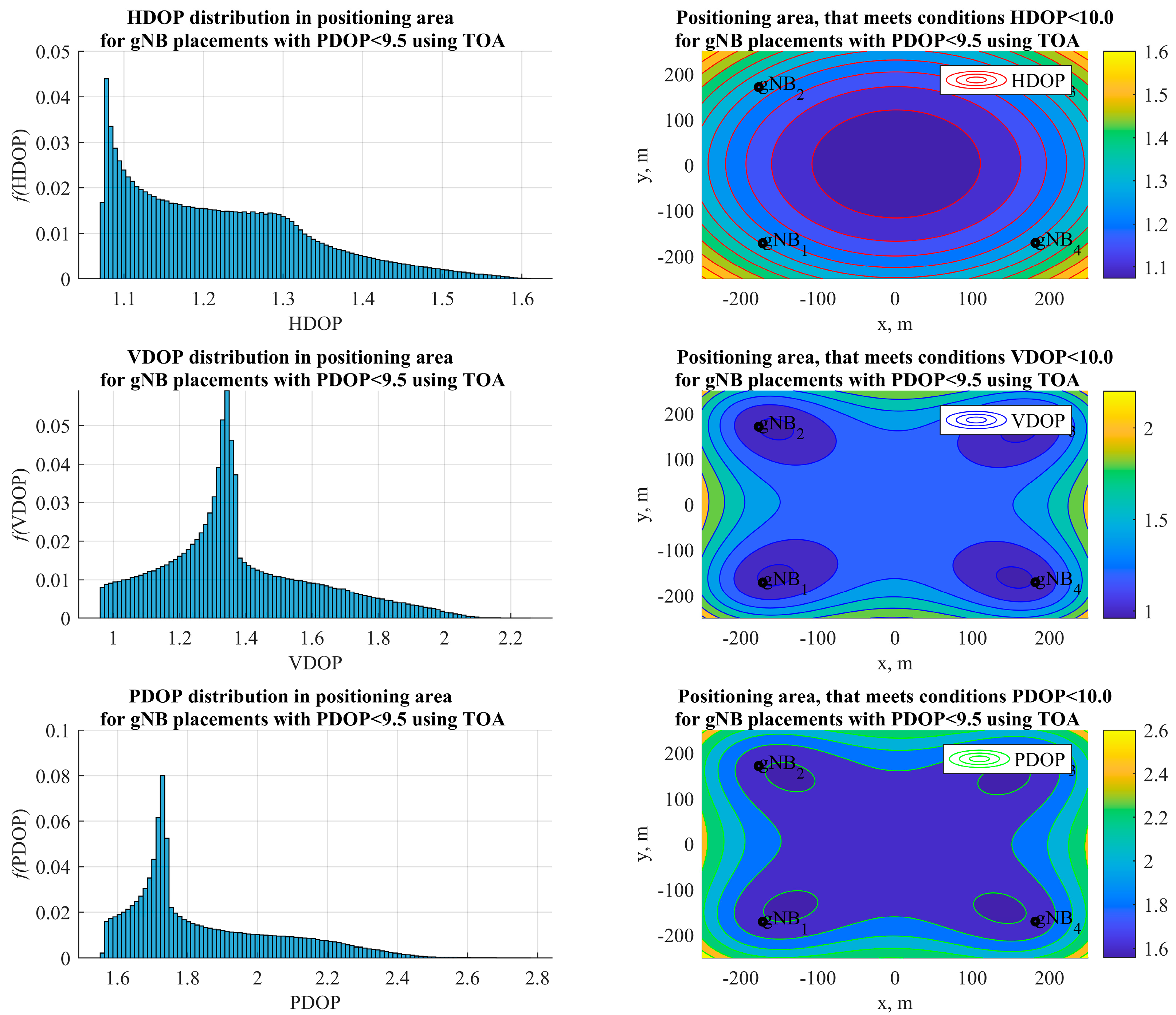
After obtaining the topologies of four gNBs in Figure 6, we calculated the DOP distribution for the variable UE location on the plane with a given step. In particular, f H D O P , f P D O P , and f V D O P were the resulting distributions of horizontal, vertical, and position GDOP factors of UE positioning in the location area, plotted in Figure 7.
Because it is appropriate to talk about the distribution of devices in space in UDNs of the terahertz range, the geometric factor PDOP (36), which considers all three coordinates, was chosen as the criterion for finding the locations for gNBs.
Models for the searching configurations of the four gNBs according to the DOP criteria for range measurements are presented in [42]. Next, we considered models for estimating geometric factors for the configurations of four gNBs found by the PDOP criterion for all sets of primary measurements: TOA, TDOA, AOA, TOA–AOA, and TDOA–AOA.

4.3. Models for Dilution of Precision Factors Processing

Figure 5 illustrates the distribution of the distance d n , angle φ 1 n to UE, and height h n of each gNB from the filtered gNB configurations for TOA measurement processing. Figure 6 illustrates the resulting gNB topology in space for TOA measurement processing, found from the most likely distributions of the d n , φ 1 n , and h n parameters. Figure 7 illustrates PDOP, HDOP, and VDOP distributions for the obtained gNB topologies, remaining after the initial filtering of the base stations, whose deployments caused D O P m a x to be exceeded.
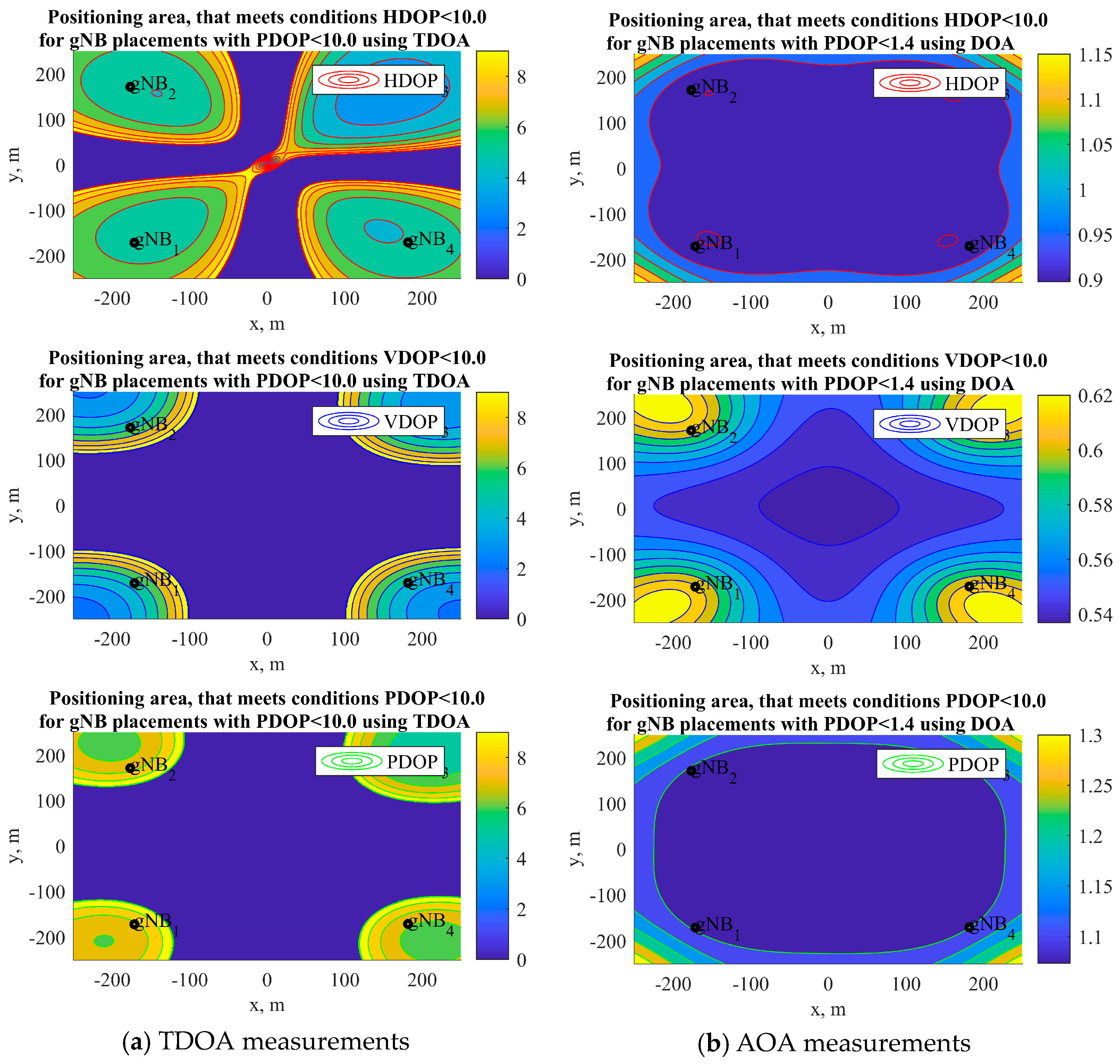
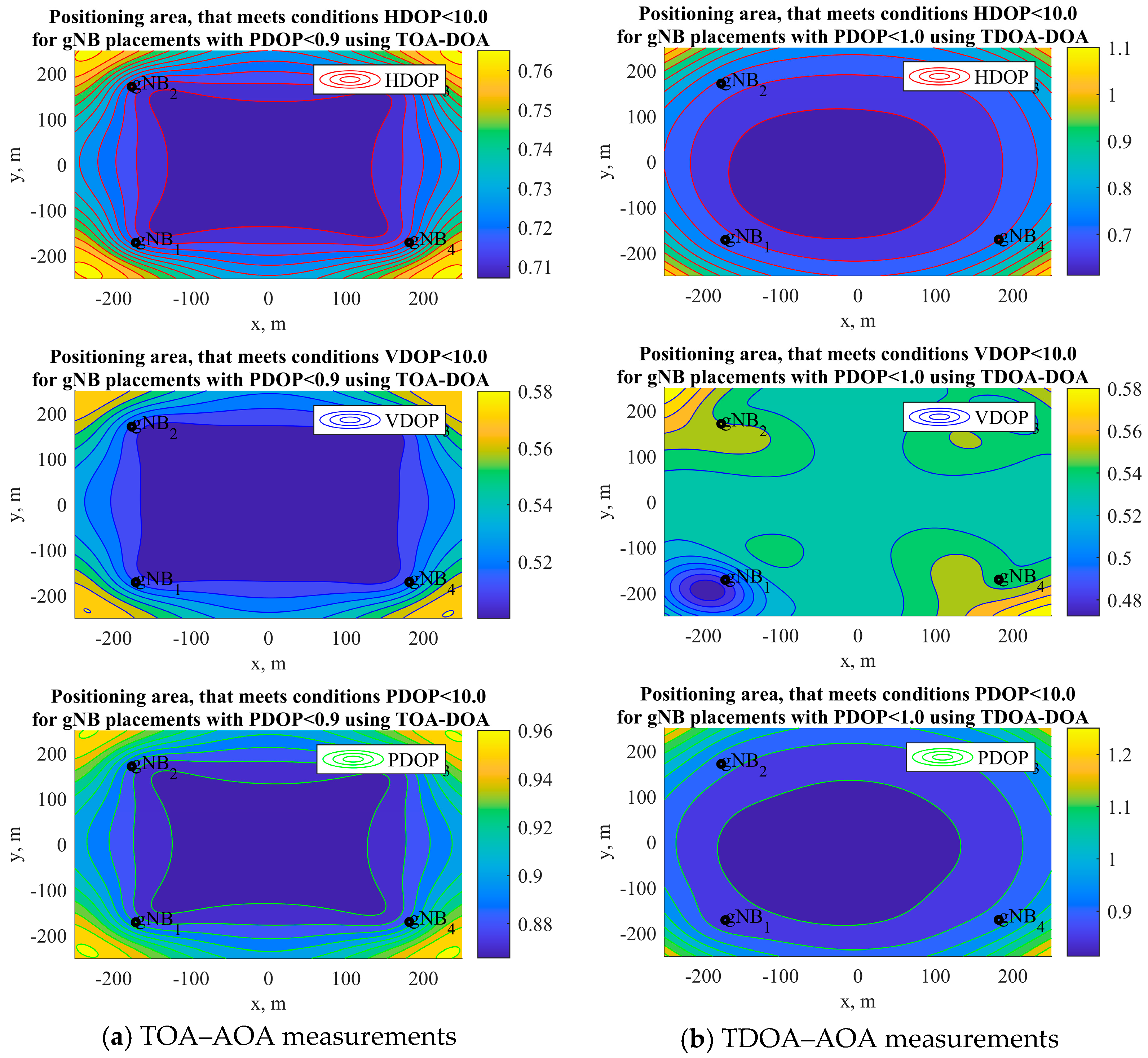
Distributions of the distance d n , angle φ 1 n to UE, and height h n of each gNB from the filtered gNB configurations and resulting gNB topologies in space for the TDOA, AOA, TOA–AOA, and TDOA–AOA measurements were generally similar to the case for the TOA measurements: four gNBs were located in the vicinity of vertices of the square of the positioning area. Figure 8 and Figure 9 illustrate the PDOP, HDOP, and VDOP distributions for the obtained gNB topologies for the TDOA, AOA, TOA–AOA, and TDOA–AOA measurements.
The choice of four gNBs for the topology search can be explained by the fact that existing work in this field [50,51,52,53,54,55,56,57,58,59,60,61] usually treats the layout of four base stations. To compare the presented results with known ones, we used the PDOP criterion with TOA and TDOA primary measurement processing. If we consider the deployment scale, we can see that the presented PDOP contours for TOA measurements in Figure 7 and for the TDOA measurements in Figure 8 are more than one and do not contradict the corresponding contours for range and pseudo-range measurements and lowest GDOP analytical estimate 2 / N in [61], thus confirming the correctness of the developed mathematical and simulation models.

4.4. DOP for Topology of Four gNB Simulation Results Discussion

The comparison of a set of PDOP, HDOP, and VDOP contours for the obtained gNB configurations, using AOA and combined TOA–AOA and TDOA–AOA measurement processing in Figure 9, is difficult due to the lack of similar results in a 3D space.
An analysis of d n , φ 1 n distributions revealed that the most suitable topology for the case of four gNBs with the PDOP criterion is square, when the gNBs are well spaced from the UE in the center, which is consistent with known results. Furthermore, an analysis of the DOP models, presented above in Figure 5, Figure 6, Figure 7, Figure 8 and Figure 9, allows us to draw the following conclusions:
1. The topologies of the four gNBs found from the most probable distributions of the base station location parameters, relative to the fixed UE coordinates, for TOA, TDOA, AOA, TOA–AOA, and TDOA–AOA measurements, are generally similar: four gNBs are located in the vicinity of vertices of the square of the positioning area; gNB heights are selected as the largest of the allowable vertical placement area.
2. The most uniform working area according to the HDOP, VDOP, and PDOP factors, as well as the lowest values of the DOP factors for reducing accuracy horizontally, vertically, and in space, is provided by the combined TOA–AOA measurement processing; in this case, the DOP values in the entire positioning area at a fixed height of the UE are less than one, which is considered to be close to the ideal result in radio navigation.
3. The HDOP, VDOP, and PDOP contour plots for the combined TOA–AOA and TDOA–AOA measurement processing with four gNBs yielded DOP values below 1 and are less than the lower-bound 2 / N with N optimally located base stations for TOA or TDOA-only measurement processing.
The presented algorithmic, methodological, and software tools for the gNB topology search in space, based on the dilution of the precision criterion, assume a fixed placement of the UE in the ultra-dense network positioning service area. The direction of the development of the approach is to remove the restriction on the fixed placement of the UE in the UDN positioning service area and to increase the number of gNBs to more than four. Such an approach will make it possible to search for and justify gNB topology in UDN scenarios.

5. Algorithm for Topology Search Using DOP Criterion in UDN Formalization

5.1. Algorithm Restrictions

The analysis of methods and models for the topology search, using the dilution of the precision criterion in ultra-dense network positioning service area for fixed gNB location, carried out in the first part of the study showed that this approach is multi-parametric. The solution of a multi-parameter problem by enumeration was carried out by the so-called “greedy algorithms” (brute-force search) and can provide the most suitable topologies of gNBs under the given constraints. Let us formulate the following two fundamental limitations and restrictions from the previous analysis.
Firstly, the found gNB topology in space satisfied the criterion of maximum allowable selected DOP. With one criterion, for example PDOP, the remaining DOP factors in the horizontal plane (HDOP) and the vertical plane (VDOP) turned out to be “not bad” at best.
Secondly, the found gNB topology in space turned out to be the best for a given fixed location of the UE in the center of the positioning service area. At points other than the center of the positioning service area selected with a given step on the plane, the target (for example, PDOP) and the remaining geometric factors (for example, HDOP and VDOP) decreased; the DOP analysis with UE variation in height was not performed.
For the analysis of 5G, B5G, and 6G UDNs, it is rational to accept the first restriction and search for the gNB topology solely using the most common PDOP criterion in space. As for the second restriction, it was removed in this work, and the search for gNB coordinates was carried out by iterative enumeration of all possible locations of stationary gNB and mobile UE with a given step in space to minimize PDOP in the selected positioning service area. Furthermore, because the most uniform positioning service area, according to the HDOP, VDOP, and PDOP criteria, as well as the smallest values of the DOP factor on the plane (HDOP), in height (VDOP), and space (PDOP), was provided by the combined range and angle measurement processing, the gNB topology search by the enumeration method will be carried out further for joint TOA–AOA measurements.

5.2. Algorithm Formalization

Algorithm, methodology, and software for the gNB topology search in space was designed to use N gNB (larger, than four) in estimating the coordinates of one UE with a location that varies in a given positioning service area. The initial data are presented in Table 1: the sizes of the gNB and UE location area are specified by the sizeh and UEsizeh parameters, respectively, and maximum height gNB sizev; UE location height UEsizev; grid step of the UE location on the plane UEsteph; maximum number of iterations of searching for the position of one gNB M; search criterion dop_case(HDOP, VDOP, PDOP); initial search step for gNB placement on the plane dSizeHDefault; initial step for gNB placement in height dSizeVDefault; number of cycles of the search algorithm Nopt.
Algorithm searches for gNB placements by the criterion of minimizing the average DOP over all UE locations in grid, specified as Xue=[-UEsizeh/2:UEsteph:UEsizeh/2], Yue=[-UEsizeh/2:UEsteph:UEsizeh/2], at fixed height UEsizev. The position search process started by setting the initial coordinates of the gNB. The first 4 gNBs were evenly spaced relative to the origin at a distance of sizeh/2 and a height of sizev/2. Additional gNBs could be located at the origin of the coordinates or at a point with random coordinates from a given gNB positioning service area. In the first cycle of the gNB topology search algorithm, a base station location search was carried out for four gNBs (the minimum number of gNBs for positioning the UE in space) without additional gNBs, and then topology search algorithm works for each additional gNB were carried out. In subsequent Nopt−1 cycles, a gNB topology search was carried out, considering all gNBs. Each search iteration for an individual gNB included the following procedures:
1. First, the initial coordinates of gNBs, the search step on the plane dSizeHDefault, and the height dSizeVDefault were initialized.
2. Next, D O P 0 was calculated for the current coordinates of all involved gNBs.
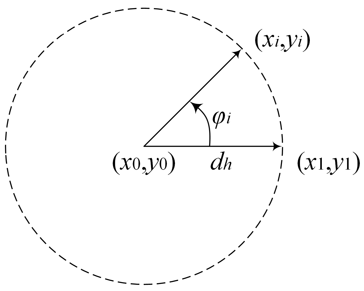
3. Then, the coordinates x i , y i , z i were calculated for N n e x t points in the vicinity of the selected kth gNB with coordinates x 0 , y 0 , z 0 . The search can be carried out on plane, then, the points x i , y i , z i were located on a circle (Figure 10) with a radius d h and center x 0 , y 0 , z 0 :
x i = x 0 + cos φ i d h ;
y i = y 0 + sin φ i d h ;
z i = z 0 .
The search could be carried out in height, then, for this case, the coordinates of only two points were calculated:
x 1 = x 2 = x 0 ;
y 1 = y 2 = y 0 ;
z 1 = z 0 d v ; z 2 = z 0 + d v .
The search could be carried out in space, then, for this case, the points were located on the surface of an ellipsoid with horizontal semi-axes d h , vertical semi-axes d v , and center point ( x 0 , y 0 , z 0 ) :
x i = x 0 + cos θ i cos φ i cos θ i d h ;
y i = y 0 + cos θ i sin φ i d h ;
z i = z 0 + sin θ i d v ;
φ i = 2 π N n e x t i , i = 0 N n e x t 1 ;
θ i = π N n e x t i , i = N n e x t 2 N n e x t 2 ;
where x i , y i , z i are the coordinates of the ith point on the plane in the vicinity of the selected gNBs; x 0 , y 0 , z 0 are the initial gNB coordinates; φ i is the azimuth angle of the ith point; θ i is the elevation angle of the ith point; d h is the current search step on the plane; d v is the current search step in height. If the coordinate of the ith point is out of range of acceptable values, then it is equal to this limit. At the end of this step, there were N n e x t gNB configurations (topologies) that differed in the coordinates of the kth gNB.
4. Next, D O P n e x t was calculated for each gNB configuration obtained in the previous step. Among the obtained values of D O P n e x t , the algorithm found the minimum D O P n e x t _ m i n value and the corresponding gNB configuration (topology).
5. If the condition D O P n e x t _ m i n < D O P 0 was satisfied, then the gNB configuration, corresponding to D O P n e x t _ m i n , was selected as the initial topology with corresponding gNB coordinates for the next iteration of the search process, and the algorithm continued searching for the position of the kth gNB according to procedures 2–6.
6. If D O P n e x t _ m i n > D O P 0 , then the search step for the gNB position on the plane and/or in height decreased to the value:
d h = μ h d h , d v = μ v d v , μ h < 1 , μ v < 1 ;
The search step reduction coefficients μ h and μ v were chosen empirically and were equal to 0.7 and 0.85, respectively. The algorithm continued to work according to procedures 2–6 until the completion condition was reached.
7. The process of searching for the position of the selected kth gNB ended if the maximum number of iterations was completed or the step of searching for the position on the plane and/or in height became less than 1 m.

6. Algorithm for Topology Search Using DOP Criterion in UDN Simulation

6.1. Algorithm Initialization

Next, we considered an example of a simulation of the algorithm for topology search using the DOP criterion in UDNs for the following initial data: size of the gNB location area is sizeh = 500 m; size of the positioning area of the UE is UEsizeh = 500 m; maximum gNB height is sizev = 100 m; maximum height at which UE (for example, in stadium) can be is UEsizev = 100 m; UE location grid step on the plane UEsteph = 10 m; UE location grid step in the heigh UEstepv = 10 m; maximum number of iterations in the search for the position of one gNB is M = 10; search criteria dop_case = PDOP; initial step of position search on the plane dSizeHDefault = 10 m; initial step of height position search dSizeVDefault = 1 m; number of search algorithm cycles Nopt = 3; gNB number N = 5, 6, and 7. During the operation of the algorithm, the positions of the first four gNBs were searched according to the minimum PDOP criterion, then, the following gNBs were added to the gNB configuration, and their placement was searched. Subsequent cycles of the algorithm were carried out considering all gNBs. Comparing the algorithm proposed here with an approach of the four gNB topology searches presented in Section 4, we emphasize that this empirical algorithm is intended for the configuration of more than four gNBs. In particular, the first four gNBs expectedly were located in the vertices of the positioning service area, which was consistent with the lowest GDOP in the 2D scenarios derived in [61].

6.2. Algorithm Procedure Simulation Analysis

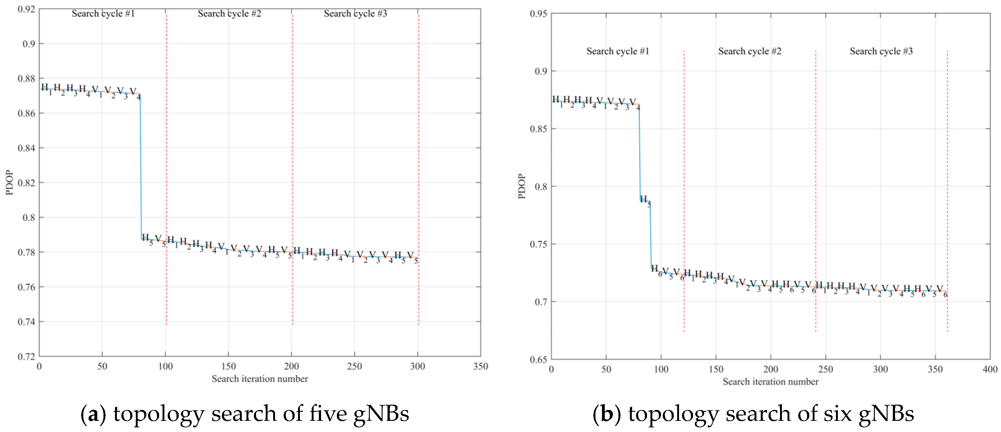
In the beginning of the algorithm, we initialized the number of algorithm search cycles; in current realization, it equaled Nopt = 3 and is illustrated in Figure 11 for the case of the five and six gNBs. For the case of more than four base stations, each additional gNB was added to the search process sequentially.
The main search function search_opt took the following input parameters: nk—gNB number, whose position is being searched; gNBpos—array of coordinates of all gNBs; ueX, ueY, and ueZ—array of UE coordinates; dSizeH—search step on the plane; dSizeV—search step in height; angStep—array of azimuths, specifying the direction of gNB position search step; Xlim, Ylim, and Zlim—array of gNB position bounds; maxIter—maximum number of iterations of the search process; dop_case—search criterion (HDOP, VDOP, and PDOP); optDir—position search plane (on the plane and in height). Main search function search_opt produces the following output parameters: gNBpos—gNB coordinates after searching the position of the nk-th gNB; gNBposP—intermediate gNB coordinates after nk-th gNB position search; dopP—intermediate DOP values after search of the nk-th gNB position; i—number of iterations performed to search the position of the nk-th gNB.
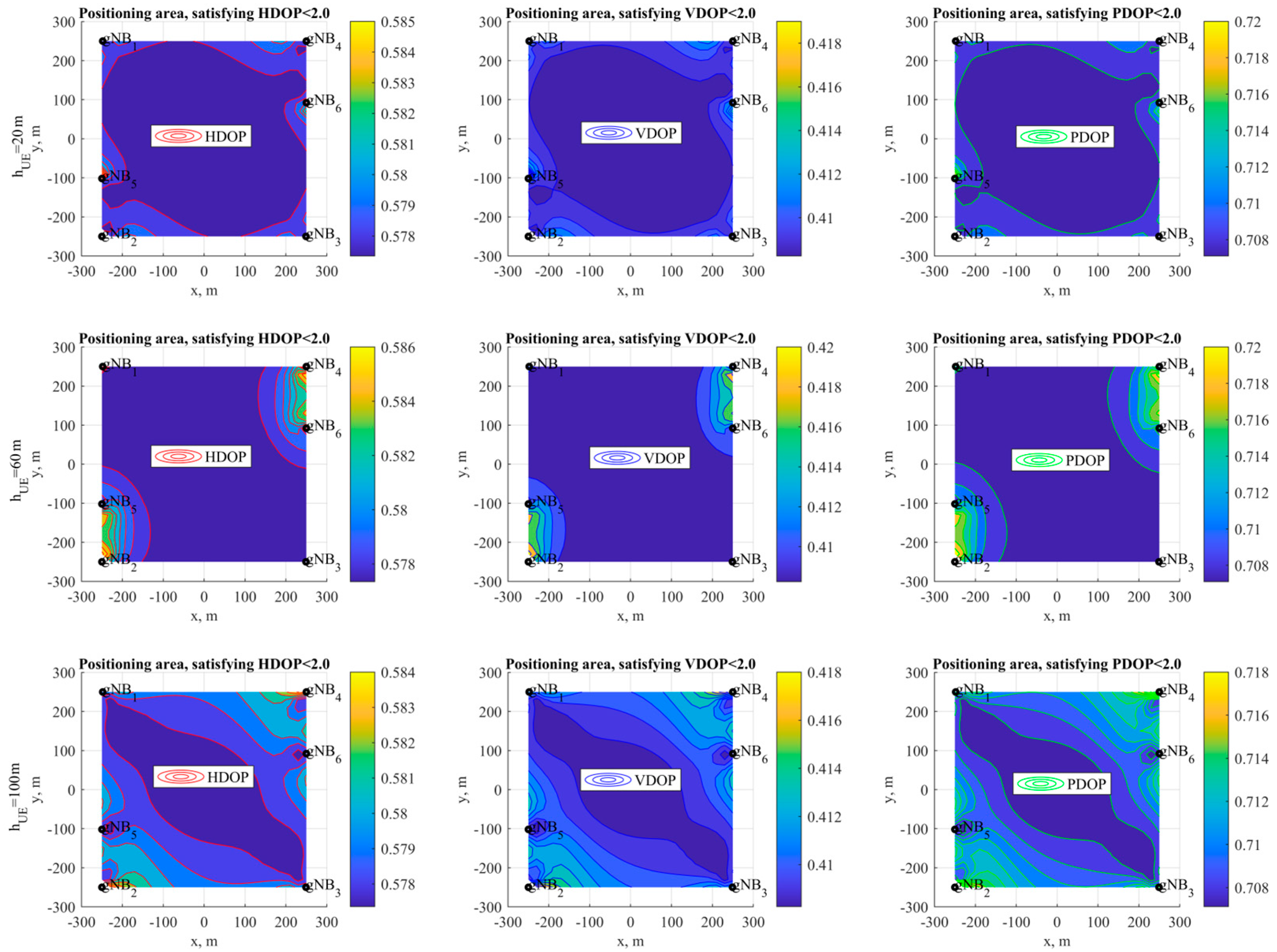
The analysis of the simulation results for the topology search in Figure 11 allows us to conclude that increasing the gNB number from five to six leads to a mean PDOP decrease from 0.78 to 0.71, which is close to the ideal result in radio navigation. In this graph, the symbols H and V denote the processes of searching for placement of gNBs on the plane and in height, respectively, and the gNB number is designated by index. PDOP decrease for search process are indicated by colors: blue line indicates DOP decrease inside algorithm search cycle and red dotted line defines search cycle boundaries. Figure 12 illustrates HDOP, VDOP, and PDOP on different UE heights in the positioning area for the resultant topologies of six gNBs.

7. Conclusions

In this paper, we developed an algorithm for the iterative enumeration of all possible locations of base stations and user equipment with a given step in space to minimize the geometric dilution of the precision factor of user equipment location estimation in positioning a service area. The algorithm allows to search for and justify the locations of base stations and/or routers in scenarios of the ultra-dense placement of devices in a space. Based on a simulation, we demonstrate that a PDOP less than one for the Gazprom Arena with only five gNBs is possible.
The MATLAB source code for the presented algorithm for the topology search using the DOP criterion in the UDN positioning service area can be downloaded at: https://github.com/grihafokin/Topology_search_using_DOP (accessed on 27 March 2023).

Author Contributions

Conceptualization, A.K. and G.F.; methodology, G.F.; software, G.F.; validation, G.F. and A.K.; formal analysis, A.K.; investigation, G.F.; resources, G.F.; data curation, A.K.; writing—original draft preparation, G.F.; writing—review and editing, A.K.; visualization, G.F.; supervision, A.K.; project administration, A.K.; funding acquisition, A.K. All authors have read and agreed to the published version of the manuscript.

Funding

The studies at St. Petersburg State University of Telecommunications. prof. M.A. Bonch-Bruevich were supported by the Ministry of Science and High Education of the Russian Federation by the grant 075-12-2022-1137.

Data Availability Statement

Not applicable.

Acknowledgments

Research and development were performed in The Bonch-Bruevich Saint Petersburg State University of Telecommunications and supported by the Ministry of Science and High Education of the Russian Federation by grant number 075-15-2022-1137.

Conflicts of Interest

The authors declare no conflict of interest.

References

  1. Kanhere, O.; Rappaport, T.S. Position Location for Futuristic Cellular Communications: 5G and Beyond. IEEE Commun. Mag. 2021, 59, 70–75. [Google Scholar] [CrossRef]
  2. Bartoletti, S.; Chiaraviglio, L.; Fortes, S.; Kennouche, T.E.; Solmaz, G.; Bernini, G.; Giustiniano, D.; Widmer, J.; Barco, R.; Siracusano, G.; et al. Location-based analytics in 5G and beyond. IEEE Commun. Mag. 2021, 59, 38–43. [Google Scholar] [CrossRef]
  3. Bartoletti, S.; Wymeersch, H.; Mach, T.; Brunnegård, O.; Giustiniano, D.; Hammarberg, P.; Keskin, M.F.; Lacruz, J.O.; Razavi, S.M.; Rönnblom, J.; et al. Positioning and sensing for vehicular safety applications in 5G and beyond. IEEE Commun. Mag. 2021, 59, 15–21. [Google Scholar] [CrossRef]
  4. Conti, A.; Morselli, F.; Liu, Z.; Bartoletti, S.; Mazuelas, S.; Lindsey, W.C.; Win, M.Z. Location awareness in beyond 5G networks. IEEE Commun. Mag. 2021, 59, 22–27. [Google Scholar] [CrossRef]
  5. De Lima, C.; Belot, D.; Berkvens, R.; Bourdoux, A.; Dardari, D.; Guillaud, M.; Isomursu, M.; Lohan, E.S.; Miao, Y.; Barreto, A.N.; et al. Convergent Communication, Sensing and Localization in 6G Systems: An Overview of Technologies, Opportunities and Challenges. IEEE Access 2021, 9, 26902–26925. [Google Scholar] [CrossRef]
  6. Bourdoux, A.; Barreto, A.N.; van Liempd, B.; de Lima, C.; Dardari, D.; Belot, D.; Lohan, E.S.; Seco-Granados, G.; Sarieddeen, H.; Wymeersch, H.; et al. 6G White Paper on Localization and Sensing. arXiv 2020, arXiv:2006.01779. Available online: https://arxiv.org/pdf/2006.01779.pdf (accessed on 27 March 2023).
  7. Mogyorósi, F.; Revisnyei, P.; Pašić, A.; Papp, Z.; Törös, I.; Varga, P.; Pašić, A. Positioning in 5G and 6G Networks—A Survey. Sensors 2022, 22, 4757. [Google Scholar] [CrossRef] [PubMed]
  8. Isaia, C.; Michaelides, M.P. A Review of Wireless Positioning Techniques and Technologies: From Smart Sensors to 6G. Signals 2023, 4, 90–136. [Google Scholar] [CrossRef]
  9. Zhang, Z.; Xiao, Y.; Ma, Z.; Xiao, M.; Ding, Z.; Lei, X.; Karagiannidis, G.K.; Fan, P. 6G Wireless Networks: Vision, Requirements, Architecture, and Key Technologies. IEEE Trans. Veh. Technol. 2019, 14, 28–41. [Google Scholar] [CrossRef]
  10. Jia, X.; Liu, P.; Qi, W.; Liu, S.; Huang, Y.; Zheng, W.; Pan, M.; You, X. Link-Level Simulator for 5G Localization. arXiv 2022, arXiv:2212.12998. Available online: https://arxiv.org/pdf/2212.12998.pdf (accessed on 27 March 2023).
  11. Chen, H.; Sarieddeen, H.; Ballal, T.; Wymeersch, H.; Alouini, M.-S.; Al-Naffouri, T.Y. A Tutorial on Terahertz-Band Localization for 6G Communication Systems. IEEE Commun. Surv. Tutor. 2022, 24, 1780–1815. [Google Scholar] [CrossRef]
  12. Chen, H.; Keskin, M.F.; Aghdam, S.R.; Kim, H.; Lindberg, S.; Wolfgang, A.; Abrudan, T.E.; Eriksson, T.; Wymeersch, H. Modeling and Analysis of 6G Joint Localization and Communication under Hardware Impairments. arXiv 2023, arXiv:2301.01042. Available online: https://arxiv.org/pdf/2301.01042.pdf (accessed on 27 March 2023).
  13. Chen, H.; Ballal, T.; Eltayeb, M.E.; Al-Naffouri, T.Y. Antenna Selection in Switch-Based MIMO Arrays via DOA Threshold Region Approximation. IEEE Trans. Veh. Technol. 2022, 71, 12344–12349. [Google Scholar] [CrossRef]
  14. Chen, H.; Aghdam, S.R.; Keskin, M.F.; Wu, Y.; Lindberg, S.; Wolfgang, A.; Gustavsson, U.; Eriksson, T.; Wymeersch, H. MCRB-Based Performance Analysis of 6G Localization under Hardware Impairments. arXiv 2023, arXiv:2204.12788. Available online: https://arxiv.org/pdf/2204.12788.pdf (accessed on 27 March 2023).
  15. Liu, F.; Cui, Y.; Masouros, C.; Xu, J.; Han, T.X.; Eldar, Y.C.; Buzzi, S. Integrated Sensing and Communications: Toward Dual-Functional Wireless Networks for 6G and Beyond. IEEE J. Sel. Areas Commun. 2022, 40, 1728–1767. [Google Scholar] [CrossRef]
  16. Yildiz, O.; Khalili, A.; Erkip, E. Hybrid Beam Alignment for Multi-Path Channels: A Group Testing Viewpoint. In Proceedings of the 2022 56th Asilomar Conference on Signals, Systems, and Computers, Pacific Grove, CA, USA, 31 October–2 November 2022; pp. 6–10. [Google Scholar] [CrossRef]
  17. Behravan, A.; Yajnanarayana, V.; Keskin, M.F.; Chen, H.; Shrestha, D.; Abrudan, T.E.; Svensson, T.; Schindhelm, K.; Wolfgang, A.; Lindberg, S.; et al. Positioning and Sensing in 6G: Gaps, Challenges, and Opportunities. IEEE Veh. Technol. Mag. 2023, 18, 40–48. [Google Scholar] [CrossRef]
  18. Mateos-Ramos, J.M.; Häger, C.; Keskin, M.F.; Magoarou, L.L.; Wymeersch, H. Model-Driven End-to-End Learning for Integrated Sensing and Communication. arXiv 2022, arXiv:2212.10211. Available online: https://arxiv.org/pdf/2212.10211.pdf (accessed on 27 March 2023).
  19. Rivetti, S.; Mateos-Ramos, J.M.; Wu, Y.; Song, J.; Keskin, M.F.; Yajnanarayana, V.; Häger, C.; Wymeersch, H. Spatial Signal Design for Positioning via End-to-End Learning. arXiv 2022, arXiv:2209.12818. Available online: https://arxiv.org/pdf/2209.12818.pdf (accessed on 27 March 2023). [CrossRef]
  20. Wymeersch, H.; Pärssinen, A.; Abrudan, T.E.; Wolfgang, A.; Haneda, K.; Sarajlic, M.; Leinonen, M.E.; Keskin, M.F.; Chen, H.; Lindberg, S.; et al. 6G Radio Requirements to Support Integrated Communication, Localization, and Sensing. In Proceedings of the 2022 Joint European Conference on Networks and Communications & 6G Summit (EuCNC/6G Summit), Grenoble, France, 7–10 June 2022; pp. 463–469. [Google Scholar] [CrossRef]
  21. Wymeersch, H.; Shrestha, D.; De Lima, C.M.; Yajnanarayana, V.; Richerzhagen, B.; Keskin, M.F.; Schindhelm, K.; Ramirez, A.; Wolfgang, A.; De Guzman, M.F.; et al. Integration of Communication and Sensing in 6G: A Joint Industrial and Academic Perspective. In Proceedings of the 2021 IEEE 32nd Annual International Symposium on Personal, Indoor and Mobile Radio Communications (PIMRC), Helsinki, Finland, 13–16 September 2021; pp. 1–7. [Google Scholar] [CrossRef]
  22. Zheng, P.; Ballal, T.; Chen, H.; Wymeersch, H.; Al-Naffouri, T.Y. Localization Coverage Analysis of THz Communication Systems with a 3D Array. In Proceedings of the GLOBECOM 2022—2022 IEEE Global Communications Conference, Rio de Janeiro, Brazil, 4–8 December 2022; pp. 5378–5383. [Google Scholar] [CrossRef]
  23. Yajnanarayana, V.; Wymeersch, H. Multistatic Sensing of Passive Targets Using 6G Cellular Infrastructure. arXiv 2022, arXiv:2211.05340. Available online: https://arxiv.org/pdf/2211.05340.pdf (accessed on 27 March 2023).
  24. Paramonov, A.; Tonkikh, E.; Koucheryavy, A.; Tatarnikova, T.M. High Density Internet of Things Network Analysis. In Proceedings of the 20th International Conference, NEW2AN 2020, and 13th Conference, ruSMART 2020, St. Petersburg, Russia, 26–28 August 2020; pp. 307–316. [Google Scholar] [CrossRef]
  25. Yastrebova, A.; Kirichek, R.; Koucheryavy, Y.; Borodin, A.; Koucheryavy, A. Future Networks 2030: Architecture & Requirements. In Proceedings of the 2018 10th International Congress on Ultra-Modern Telecommunications and Control Systems and Workshops (ICUMT), Moscow, Russia, 5–9 November 2018; pp. 1–8. [Google Scholar] [CrossRef]
  26. Fokin, G.; Lazarev, V. Location Accuracy of Radio Emission Sources for Beamforming in Ultra-Dense Radio Networks. In Proceedings of the 2019 IEEE Microwave Theory and Techniques in Wireless Communications (MTTW), Riga, Latvia, 1–2 October 2019; pp. 9–12. [Google Scholar] [CrossRef]
  27. Lazarev, V.; Fokin, G.; Stepanets, I. Positioning for Location-Aware Beamforming in 5G Ultra-Dense Networks. In Proceedings of the 2019 IEEE International Conference on Electrical Engineering and Photonics (EExPolytech), St. Petersburg, Russia, 17–18 October 2019; pp. 136–139. [Google Scholar] [CrossRef]
  28. Fokin, G.; Lazarev, V. 3D Location Accuracy Estimation of Radio Emission Sources for Beamforming in Ultra-Dense Radio Networks. In Proceedings of the 2019 11th International Congress on Ultra-Modern Telecommunications and Control Systems and Workshops (ICUMT), Dublin, Ireland, 28–30 October 2019; pp. 1–6. [Google Scholar] [CrossRef]
  29. Fokin, G.; Bachevsky, S.; Sevidov, V. System Level Performance Evaluation of Location Aware Beamforming in 5G Ultra-Dense Networks. In Proceedings of the 2020 IEEE International Conference on Electrical Engineering and Photonics (EExPolytech), St. Petersburg, Russia, 15–16 October 2020; pp. 94–97. [Google Scholar] [CrossRef]
  30. Grewal, M.S.; Andrews, A.P.; Barton, C.G. Global Navigation Satellite Systems, Inertial Navigation, and Integration, 4th ed.; John Wiley & Sons: Hoboken, NJ, USA, 2020; 608p. [Google Scholar]
  31. Bar-Shalom, Y.; Li, X.R.; Kirubarajan, T. Estimation with Applications to Tracking and Navigation; John Wiley & Sons: Hoboken, NJ, USA, 2001; 584p. [Google Scholar]
  32. Bensky, A. Wireless Positioning Technologies and Applications (GNSS Technology and Applications), 2nd ed.; Artech House: London, UK, 2016; 450p. [Google Scholar]
  33. Roth, J.D.; Tummala, M.; McEachen, J.C. Efficient System Geolocation Architecture in Next-Generation Cellular Networks. IEEE Syst. J. 2018, 12, 3414–3425. [Google Scholar] [CrossRef]
  34. Roth, J.D.; Tummala, M.; McEachen, J.C. Fundamental Implications for Location Accuracy in Ultra-Dense 5G Cellular Networks. IEEE Trans. Veh. Technol. 2019, 68, 1784–1795. [Google Scholar] [CrossRef]
  35. Elsawy, H.; Dai, W.; Alouini, M.; Win, M.Z. Base Station Ordering for Emergency Call Localization in Ultra-Dense Cellular Networks. IEEE Access 2018, 6, 301–315. [Google Scholar] [CrossRef]
  36. 3GPP TS 22.104. Service Requirements for Cyber-Physical Control Applications in Vertical Domains; Stage 1 (Release 18). V18.3.0 (2021-12). Available online: https://portal.3gpp.org/desktopmodules/Specifications/SpecificationDetails.aspx?specificationId=3528 (accessed on 27 March 2023).
  37. 3GPP TS 22.261. Service Requirements for the 5G System; Stage 1 (Release 19). V19.1.0 (2022-12). Available online: https://portal.3gpp.org/desktopmodules/Specifications/SpecificationDetails.aspx?specificationId=3107 (accessed on 27 March 2023).
  38. 3GPP TR 22.872. Study on Positioning Use Cases; Stage 1 (Release 16). V16.1.0 (2018-09). Available online: https://portal.3gpp.org/desktopmodules/Specifications/SpecificationDetails.aspx?specificationId=3280 (accessed on 27 March 2023).
  39. 3GPP TS 38.305. NG Radio Access Network (NG-RAN); Stage 2 Functional Specification of User Equipment (UE) Positioning in NG-RAN (Release 17). V17.4.0 (2023-03). Available online: https://portal.3gpp.org/desktopmodules/Specifications/SpecificationDetails.aspx?specificationId=3310 (accessed on 27 March 2023).
  40. 3GPP TR 38.855. Study on NR Positioning Support (Release 16). V16.0.0 (2019-03). Available online: https://portal.3gpp.org/desktopmodules/Specifications/SpecificationDetails.aspx?specificationId=3501 (accessed on 27 March 2023).
  41. Gazprom Arena. Available online: https://gazprom-arena.com/eng (accessed on 27 March 2023).
  42. Fokin, G.; Sevidov, V. Model for 5G UDN Positioning System Topology Search Using Dilution of Precision Criterion. In Proceedings of the 2021 International Conference on Electrical Engineering and Photonics (EExPolytech), St. Petersburg, Russia, 14–15 October 2021; pp. 32–36. [Google Scholar] [CrossRef]
  43. Fokin, G.; Sevidov, V. Topology Search Using Dilution of Precision Criterion for Enhanced 5G Positioning Service Area. In Proceedings of the 2021 13th International Congress on Ultra-Modern Telecommunications and Control Systems and Workshops (ICUMT), Brno, Czech Republic, 25–27 October 2021; pp. 131–136. [Google Scholar] [CrossRef]
  44. Lazarev, V.O.; Fokin, G.A. Positioning Performance Requirements Evaluation for Grid Model in Ultra-Dense Network Scenario. In Proceedings of the 2020 Systems of Signals Generating and Processing in the Field of on-Board Communications, Moscow, Russia, 19–20 March 2020; pp. 1–6. [Google Scholar] [CrossRef]
  45. Fokin, G. Vehicles Tracking in 5G-V2X UDN Using Range and Bearing Measurements. In Proceedings of the 2021 IEEE Vehicular Networking Conference (VNC), Ulm, Germany, 10–12 November 2021; pp. 103–106. [Google Scholar] [CrossRef]
  46. Fokin, G.; Vladyko, A. Vehicles Tracking in 5G-V2X UDN using Range, Bearing and Inertial Measurements. In Proceedings of the 2021 13th International Congress on Ultra-Modern Telecommunications and Control Systems and Workshops (ICUMT), Brno, Czech Republic, 25–27 October 2021; pp. 137–142. [Google Scholar] [CrossRef]
  47. Fokin, G. Vehicle Positioning Requirements for Location-Aware Beamforming in 5G UDN. In Proceedings of the 2022 Intelligent Technologies and Electronic Devices in Vehicle and Road Transport Complex (TIRVED), Moscow, Russia, 10–11 November 2022; pp. 1–6. [Google Scholar] [CrossRef]
  48. Huang, J.; Liang, J.; Luo, S. Method and analysis of TOA-based localization in 5G ultra-dense networks with randomly distributed nodes. IEEE Access 2019, 7, 174986–175002. [Google Scholar] [CrossRef]
  49. Ash, J.N.; Moses, R.L. On optimal anchor node placement in sensor localization by optimization of subspace principal angles. In Proceedings of the 2008 IEEE International Conference on Acoustics, Speech and Signal Processing, Las Vegas, NV, USA, 31 March–4 April 2008; pp. 2289–2292. [Google Scholar] [CrossRef]
  50. Xhafa, A.; del Peral-Rosado, J.A.; López-Salcedo, J.A.; Seco-Granados, G. Evaluation of 5G Positioning Performance Based on UTDoA, AoA and Base-Station Selective Exclusion. Sensors 2022, 22, 101. [Google Scholar] [CrossRef] [PubMed]
  51. Posluk, M.; Ahlander, J.; Shrestha, D.; Razavi, S.M.; Lindmark, G.; Gunnarsson, F. 5G Deployment Strategies for High Positioning Accuracy in Indoor Environments. arXiv 2021, arXiv:2105.09584. Available online: https://arxiv.org/pdf/2105.09584.pdf (accessed on 27 March 2023).
  52. Deng, Z.; Wang, H.; Zheng, X.; Fu, X.; Yin, L.; Tang, S.; Yang, F. A Closed-Form Localization Algorithm and GDOP Analysis for Multiple TDOAs and Single TOA Based Hybrid Positioning. Appl. Sci. 2019, 9, 4935. [Google Scholar] [CrossRef]
  53. Roth, J.D.; Tummala, M.; Mceachen, J.C. A new probability density function for minimizing geometric dilution of precision in location-aware wireless communications. IEEE Access 2020, 8, 160461–160479. [Google Scholar] [CrossRef]
  54. Lin, Y.C.; Chen, C.S.; Shou, H.N.; Sun, C.T. Dilution of Position calculation for Accuracy Improvement in Wireless Location Systems. Adv. Mat. Res. 2011, 204, 1036–1040. [Google Scholar] [CrossRef]
  55. Dempster, A.G. Dilution of precision in angle-of-arrival positioning systems. Electron. Lett. 2006, 42, 291–292. [Google Scholar] [CrossRef]
  56. Li, B.; Zhao, K.; Shen, X. Dilution of precision in positioning systems using both angle of arrival and time of arrival measurements. IEEE Access 2020, 8, 192506–192516. [Google Scholar] [CrossRef]
  57. Miao, S.; Dong, L.; Hou, J. Dynamic base stations selection method for passive location based on GDOP. PLoS ONE 2022, 17, e0272487. [Google Scholar] [CrossRef] [PubMed]
  58. Sharp, I.; Yu, K.; Guo, Y.J. GDOP analysis for positioning system design. IEEE Trans. Veh. Technol. 2009, 58, 3371–3382. [Google Scholar] [CrossRef]
  59. Li, F.; Tu, R.; Hong, J.; Zhang, S.; Liu, M.; Lu, X. Performance Analysis of BDS–5G Combined Precise Point Positioning. Remote Sens. 2022, 14, 3006. [Google Scholar] [CrossRef]
  60. Guo, W.; Deng, Y.; Guo, C.; Qi, S.; Wang, J. Performance improvement of 5G positioning utilizing multi-antenna angle measurements. Satell. Navig. 2022, 3, 17. [Google Scholar] [CrossRef]
  61. Levanon, N. Lowest GDOP in 2-D scenarios. IEE Radar Sonar Navig. 2000, 147, 149–155. [Google Scholar] [CrossRef]
  62. Stansfield, R.G. Statistical theory of DF fixing. J. Inst. Electr. Eng. Part IIIA Radiocommun. 1947, 94, 762–770. [Google Scholar] [CrossRef]
  63. Lee, H.B. A novel procedure for assessing the accuracy of hyperbolic multilateration systems. IEEE Trans Aerosp. Electron Syst. 1975, 1, 2–15. [Google Scholar] [CrossRef]
  64. Lee, H.B. Accuracy limitations of hyperbolic multilateration systems. IEEE Trans Aerosp. Electron. Syst. 1975, 1, 16–29. [Google Scholar] [CrossRef]
  65. Torrieri, D.J. Statistical Theory of Passive Location Systems. IEEE Trans Aerosp. Electron. Syst. 1984, 20, 183–198. [Google Scholar] [CrossRef]
  66. Massatt, P.; Rudnick, K. Geometric formulas for dilution of precision calculations. Navigation 1990, 37, 379–391. [Google Scholar] [CrossRef]
  67. Manolakis, D.E. Efficient solution and performance analysis of 3-D position estimation by trilateration. IEEE Trans Aerosp. Electron. Syst. 1996, 32, 1239–1248. [Google Scholar] [CrossRef]
  68. Shin, D.H.; Sung, T.K. Comparisons of error characteristics between TOA and TDOA positioning. IEEE Trans Aerosp. Electron. Syst. 2002, 38, 307–311. [Google Scholar] [CrossRef]
  69. Spirito, M.A. On the accuracy of cellular mobile station location estimation. IEEE Trans. Veh. 2001, 50, 674–685. [Google Scholar] [CrossRef]
  70. Guvenc, I.; Chong, C.C. A survey on TOA based wireless localization and NLOS mitigation techniques. IEEE Commun. Surv. 2009, 11, 107–124. [Google Scholar] [CrossRef]
  71. Li, B.; Dempster, A.G.; Wang, J. 3D DOPs for positioning applications using range measurements. Wirel. Sens. Netw. 2011, 3, 334. [Google Scholar] [CrossRef]
  72. Choi, H.H.; Jin, M.H.; Lim, D.W.; Lee, S.J.; Park, C. Dilution of Precision Relationship between Time Difference of Arrival and Time of Arrival Techniques with No Receiver Clock Bias. J. Electr. Eng. Technol. 2016, 11, 746–750. [Google Scholar] [CrossRef]
  73. Algorithm for Topology Search Using Dilution of Precision Criterion in Ultra-Dense Network Positioning Service Area Simulator. Available online: https://github.com/grihafokin/Topology_search_using_DOP (accessed on 27 March 2023).
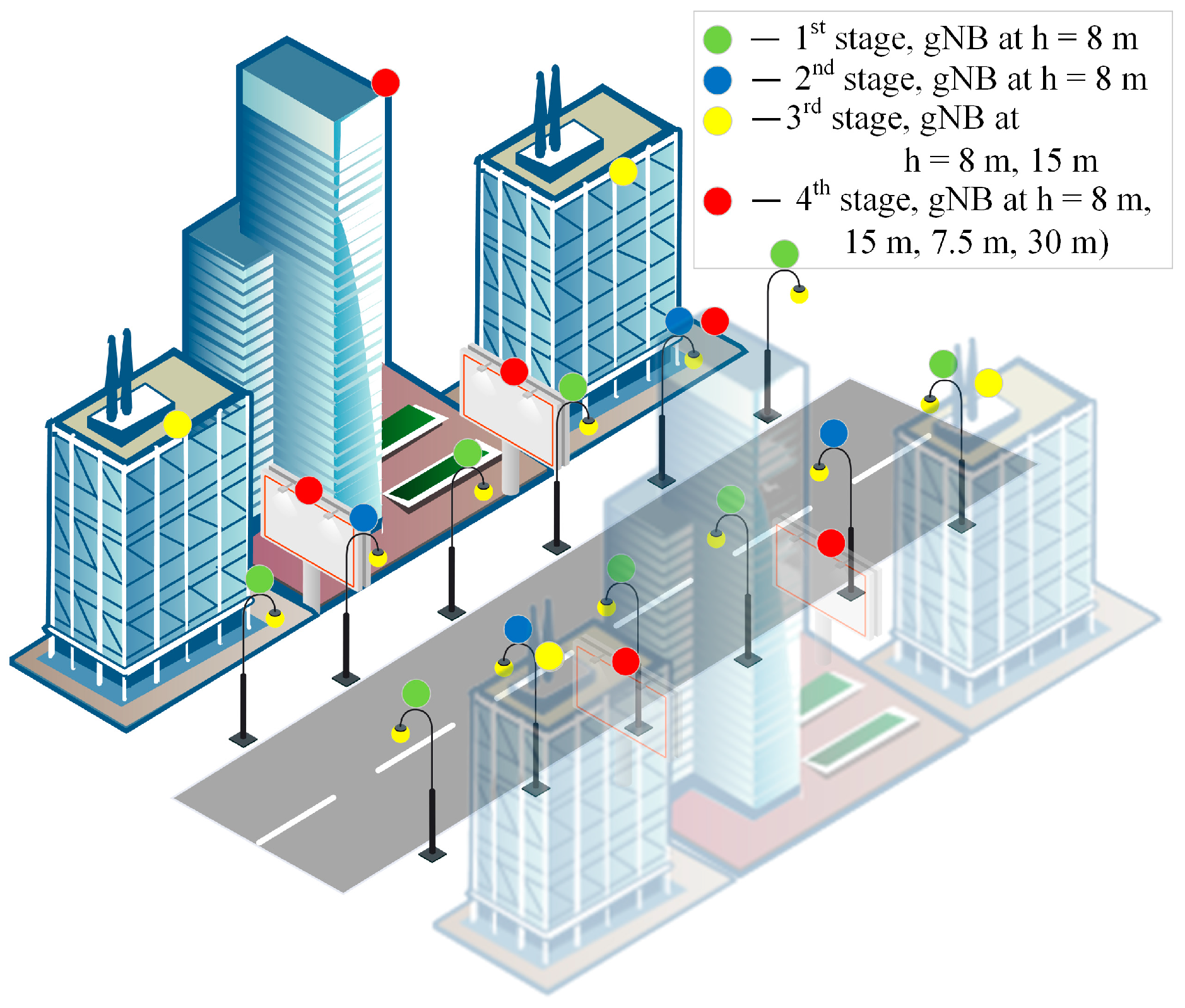
Figure 1. UDN positioning service area scenario.
Mathematics 11 02227 g001
Figure 2. UE and gNB 3D layout geometry.
Mathematics 11 02227 g002
Figure 3. Spatial grid model and example.
Mathematics 11 02227 g003
Figure 4. Four gNB layout for topology search.
Mathematics 11 02227 g004
Figure 5. Distribution of gNB parameters for TOA measurements.
Mathematics 11 02227 g005
Figure 6. Topologies of four gNBs and DOP in positioning area for TOA measurements.
Mathematics 11 02227 g006
Figure 7. DOP for gNB topology in positioning area for TOA measurements.
Mathematics 11 02227 g007
Figure 8. DOP for gNB topologies in positioning areas for TDOA and AOA measurements.
Mathematics 11 02227 g008
Figure 9. DOP for gNB topologies in positioning areas for combined measurements.
Mathematics 11 02227 g009
Figure 10. Search neighborhood on a circle.
Mathematics 11 02227 g010
Figure 11. PDOP decrease process for topology search of five and six gNBs. PDOP decrease for search process are indicated by colors: blue line indicates DOP decrease inside algorithm search cycle and red dotted line defines search cycle boundaries.
Mathematics 11 02227 g011
Figure 12. HDOP, VDOP, and PDOP on different heights in positioning area for topologies of six gNBs.
Mathematics 11 02227 g012
Table 1. Spatial parameters for topology search.
DesignationSpatial Parameter Description
nnumber of gNB base stations in a given region of space
sizehmaximum length of gNB location area in horizontal plane (on xy plane)
stephgrid spacing of possible horizontal locations of gNBs (on the xy plane)
sizevmaximum height of the gNB location area in vertical plane (altitude z)
stepvvertical grid spacing of possible gNB locations (in altitude z)
UEsizehmaximum length of the UE location area in horizontal plane (on xy plane)
UEstephgrid spacing of possible horizontal locations of UE (on the xy plane)
UEsizevmaximum height of the UE location area in vertical plane (altitude z)
UEstepvgrid spacing of possible vertical locations of UE (in altitude z)
dSizeHDefaultinitial step for optimizing the position of gNB horizontally on xy plane
dSizeVDefaultinitial step for optimizing the position of gNB vertically on altitude z
Disclaimer/Publisher’s Note: The statements, opinions and data contained in all publications are solely those of the individual author(s) and contributor(s) and not of MDPI and/or the editor(s). MDPI and/or the editor(s) disclaim responsibility for any injury to people or property resulting from any ideas, methods, instructions or products referred to in the content.