Article

Seismic Bearing Capacity Solution for Strip Footings in Unsaturated Soils with Modified Pseudo-Dynamic Approach

School of Civil Engineering, Central South University, Changsha 410075, China
*
Author to whom correspondence should be addressed.
Mathematics 2023, 11(12), 2692; https://doi.org/10.3390/math11122692
Submission received: 17 April 2023 / Revised: 5 June 2023 / Accepted: 8 June 2023 / Published: 14 June 2023
(This article belongs to the Special Issue Mathematical Modelling for Solving Engineering Problems)

Abstract

:
In engineering mathematics, the unsaturated nature of soil has a significant impact on the seismic bearing capacity solution. However, it has generally been neglected in the published literature to date. Based on the kinematic approach of limit analysis, the present study proposes a method for calculating the bearing capacity of shallow strip footings located in unsaturated soils, taking four common types of soils as examples. The modified pseudo-dynamic (MPD) approach is used to calculate the seismic forces varying with time and space, and the layerwise summation method is used to derive the power generated by the seismic forces. In the calculation of internal energy dissipation, this paper introduces the effective stress based on the suction stress to derive the cohesion expression at different depths. The analytical formula of bearing capacity is obtained by the principle of virtual work, and its value is optimized by the Sequential Quadratic Programming (SQP) algorithm. In order to verify the validity of the proposed method, the present results are compared with the solutions published so far and a good agreement is obtained. Finally, a parametric study is performed to investigate the influence of different types of parameters on the bearing capacity.

1. Introduction

Strip footings are widely used in building structures to support upper loads and transfer them to the ground due to their easy construction and high applicability. China is an earthquake-prone country, and many studies have shown that earthquakes can seriously reduce the bearing capacity of strip footings, so the accurate derivation of the seismic bearing capacity solution of strip footing is a hot issue in engineering mathematics.
An appropriate seismic load description method is the basis for the seismic bearing capacity assessment. The commonly used seismic wave description methods can be divided into two main categories: the pseudo-static method and the pseudo-dynamic method. The pseudo-static (PS) method, which is most widely used, simplifies the seismic acceleration to a constant that does not vary with time and space, and ignores the influence of parameters such as bedrock depth, foundation soil damping ratio, etc. The pseudo-dynamic method overcomes the shortcomings of the pseudo-static method, which does not respond to the time-range characteristics of ground shaking and the dynamic properties of geotechnical materials. According to the difference in the way of characterizing the amplitude of seismic waves, the pseudo-dynamic method can be subdivided into the conventional pseudo-dynamic (CPD) method, the spectral pseudo-dynamic (SPD) method, and the modified pseudo-dynamic (MPD) method. These seismic load description methods are often combined with the limit–equilibrium method [1,2,3], upper bound method of limit analysis [4,5,6,7,8] and stress characteristics [9,10] to solve the seismic bearing capacity assessment.
However, all solutions in the above studies have some limitations because they assume that the soil is in a dry or saturated state without considering the matric suction. In practical engineering terms, a number of shallow foundations are usually constructed above the water table or are often affected by rainfall, resulting in the majority of the overlying soils being unsaturated. The damage to the foundation is caused to a large extent by shear damage of the unsaturated soil. Therefore, the shear strength of unsaturated soils is a parameter that should be studied as a priority in foundation design. Several investigations have demonstrated that unsaturated soils’ shear strength can be increased by the presence of matric suction [11]. Therefore, the bearing capacity of strip footings in unsaturated soils can be significantly increased due to the development of matric suction within the unsaturated soil compared to the saturated or dry condition.
Adding matric suction from unsaturated soils to the classic bearing capacity equation is the widely accepted method for properly taking into account the impact of matric suction in the calculation of foundation bearing capacity. Fredlund et al. [12] proposed a linear equation, which is known as the two-independent stress state variable method, to represent the relationship between matric suction and shear strength of unsaturated soils. Oloo et al. [13] combined this method with Terzaghi’s formula to derive a linear equation for the bearing capacity of unsaturated layered soil pavements. However, experiments show that the relationship between matric suction and bearing capacity is not a simple linear relationship [14]. Therefore, to be more relevant to reality, Lu and Likos [11] introduced the concept of suction stress, which includes matric suction and physicochemical and bond forces, and investigated its distribution with depth and its variation with time factors such as temperature, evaporation, and precipitation. Lu et al. [15] went further and proposed a closed-form equation for the effective stress representing the shear strength behavior of unsaturated soils, which was applied to foundation-bearing capacity evaluation and slope stability by Vahedifard and Robinson [16].
It should be noted that the effective stresses of Lu et al. [15] are described in terms of a single stress variable (matric suction), modified from the expression for saturated soils. However, the theory is difficult to determine the effective stress coefficients χ and cannot explain the wetting of unsaturated soils. The effective stress expression using net stress and matric suction as two independent stress variables [12] can overcome the shortcomings of the theory. However, it creates new problems: (1) it is difficult to deal with smooth transitions between saturated and unsaturated states, (2) it is difficult to deal with the variation of intensity with suction, and (3) it is difficult to deal with the effect of saturation and the coupling with percolation. In contrast, the effective stress expression of Lu et al. [15] can be used for both shear strength and deformation analysis, and can also unify the limit equilibrium analysis of unsaturated and saturated classical soil mechanics problems.
This study aims to propose a new formulation for the estimation of the bearing capacity of strip footing under the coupled action of seismic load and matric suction, using the kinematic approach of limit analysis as a framework. The most rigorous MPD method was adopted to consider the effect of seismic forces and combined with the layerwise summation method to compute the power of seismic forces. By taking four typical unsaturated geotechnical materials (clay, silt, loess, and sand) as examples, effective stress expressions based on suction stresses are introduced to calculate the shear strength in different depths of the damage zone to establish the balance equation. Finally, key factors such as damping ratio, seismic wave wavelength, horizontal acceleration coefficient, water table depth, and flow rate are also analyzed and discussed in this solution.

2. Theoretical Framework of Seismic Bearing Capacity

2.1. Kinematic Method of Limit Analysis

The upper bound theorem of limit analysis has been widely used in studies of slope stability [17,18,19], tunnel face stability [20,21,22], and foundation-bearing capacity [23]. It can be described as follows: For a given velocity field permitted by the maneuver, the power of external work is equal to the power of the object’s internal energy dissipation:
A T i v i d A + V F i v i d V = V σ i j ε i j d V
where v i = the velocity of the failure block, σ i j and ε i j = the internal stress and the corresponding plastic strain rate, respectively, T i and F i = the surface force and body force acting on foundations, respectively, and A and V = the area and volume of the integration region, respectively.

2.2. Pseudo-Dynamic Approach

As bedrock shaking propagates to the surface in the form of seismic waves, there is spatial and temporal variability in its characteristic parameters, such as amplitude and frequency. The specific variability is related to parameters such as density, damping, and modulus of the overlying bedrock layer. To simplify the analysis, Steedman and Zeng [24] suggested a method that ignores the change of wave velocity and vibration frequency during the propagation of seismic waves, called the conventional pseudo-dynamic (CPD) method. The amplitude of vibration acceleration varies linearly as the seismic wave propagates to the surface, and the amplification factor is f. The bedrock burial depth is H, and the vibration acceleration of the transverse wave (wavelength λ , period T ) at the depth z below the surface is:
a h ( z , t ) = ( f + 1 - f H z ) k h g sin ( 2 π t T H z λ )
where kh = horizontal seismic acceleration coefficient, g = gravitational acceleration. It is worth paying attention to how to determine the wavelength value of seismic wave λ . As is known to all, the magnitude of the wavelength λ is equal to the product of wave velocity v s and period T , i.e., λ = v s T . The shear wave velocity v s of soil is mainly related to the type and characteristics of the site soil, as shown in Table 1. Generally, in denser soil, the propagation speed of seismic waves is faster. The period of seismic wave T generally adopts the designed characteristic period of ground motion, which can comprehensively reflect the influence of such factors as earthquake magnitude, epicentral distance, and site category, as shown in Table 2. For specific site categories and site grouping, please refer to the Code for the seismic design of buildings [25].
However, the CPD method cannot satisfy the boundary condition at z = 0. Therefore, Bellezza [26] proposes a modified pseudo-dynamic (MPD) method, which is the most rigorous method for assessing seismic effects. The MPD method considers that the soil below the foundation follows more realistic visco-elastic properties rather than linear elastic properties, and considers the attenuation of the amplitude of seismic waves by soil damping ratio D. The expression of S-wave seismic acceleration obtained by the MPD method is:
a h ( z , t ) = a h 0 ( C s 2 + S s 2 ) [ ( C s C s z + S s S s z ) cos ( ω t ) + ( S s C s z C s S s z ) sin ( ω t ) ]
where
a h 0 = k h g
C s z = cos ( y 1 z H ) cosh ( y 2 z H )
S s z = sin ( y 1 z H ) sinh ( y 2 z H )
C s = cos ( y 1 ) cosh ( y 2 )
S s = sin ( y 1 ) sinh ( y 2 )
y 1 = 2 π H λ 1 + 4 D 2 + 1 2 ( 1 + 4 D 2 )
y 2 = 2 π H λ 1 + 4 D 2 1 2 ( 1 + 4 D 2 )
In addition, there is an in-between method, which is known as the spectral pseudo-dynamic (SPD) method. The soil is a visco-elastic material as in the MPD method, and calculates a h ( z , t ) with the same formula as the CPD method, except that the amplification factor is changed to a binary function about the damping ratio and wavelength, which is expressed as follows:
f = 1 cos 2 ( 2 π H / λ ) + ( D 2 π H / λ ) 2

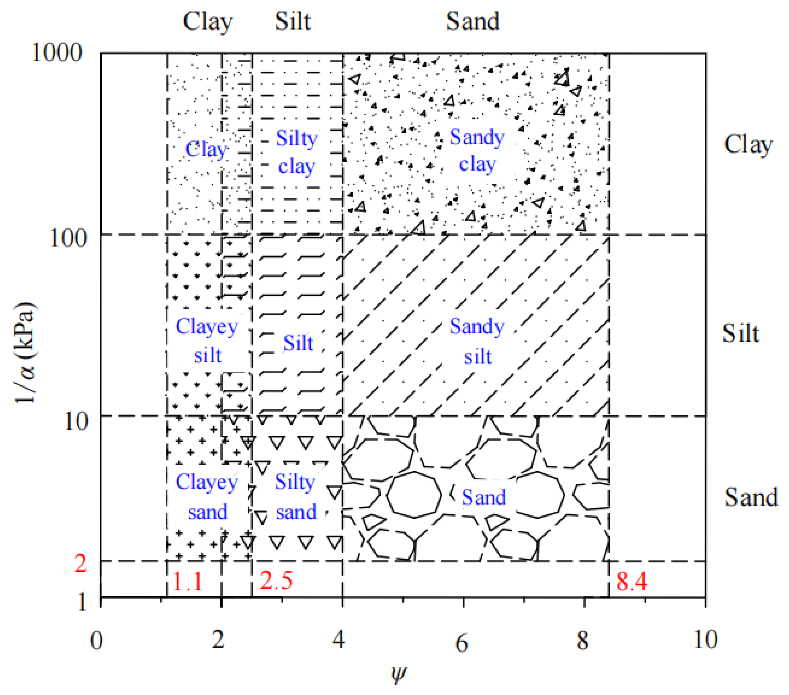
2.3. Cohesion of Unsaturated Soils

The study of effective stresses in unsaturated soils is the most fundamental and crucial in the study of unsaturated soils. The calculation of effective stresses in unsaturated soils can be divided into the single stress variable method and the double stress variable method proposed by Fredlund et al. [12], depending on the number of stress variables. On this basis, Lu and Likos [11] proposed a new effective stress calculation equation for both saturated and unsaturated soils by studying the suction stress characteristic curves:
σ = σ u a σ s
where σ = the effective stress, σ = the total stress, u a = the pore air pressure; and σ s = the suction stress. It is worth stating that suction stress is a broad concept that includes all the principal forces between soil particles. To quantify it, Lu et al. [15] proposed a closed-form equation, as follows:
σ s = ( u a u w ) ( u a u w ) 0 ( u a u w ) 1 + α ( u a u w ) ψ ( ψ 1 ) / ψ ( u a u w ) > 0
where u w = the pore water pressure; u a u w = the matric suction, α , whose reciprocal equals the air-entry pressure, varies from 0.0 to 0.5 kPa−1 and ψ is a dimensionless constant that reflects the breadth of soil pore size, whose general range of value is 1.1–8.5. Both α and ψ are the fitting parameters of SWCC, and their specific values can be referred to in Figure 1: ( u a u w ) 0 means saturated soil, in which case substituting Equation (13) into (12) yields the classical Terzaghi’s effective stress equation σ = σ u w . On the contrary, ( u a u w ) > 0 represents unsaturated soil, which is the present research object to evaluate the bearing capacity.
In order to obtain an analytical solution for the matric suction profile, Gardner’s exponential model was applied [27]:
k = k s e α ( u a u w )
where k , k s = hydraulic conductivity of unsaturated and saturated soils, respectively. Assuming that the matric suction is zero at the water table (z = 0) and flow rate q is fixed, the matric suction profile under a one-dimensional steady flow can be derived as:
u a u w = 1 α ln ( 1 + q k s ) e γ w α z q k s
where γ w = unit weight of water, taken 10   kN / m 3 , k s = saturated hydraulic conductivity, and z = height above the water table. A positive value of q denotes infiltration, whereas a negative number denotes evaporation. Substitution of Equation (15) into (13) gives an expression for the suction stress of unsaturated soils, which clearly involves four constants, including the flow case q and the characteristic soil parameters ( α , ψ , k s ):
σ s = 1 α ln ( 1 + q k s ) e γ w α z q k s 1 + ln ( 1 + q k s ) e γ w α z q k s ψ ( ψ 1 ) / ψ
Calculations reveal that the value of σ s is negative in the one-dimensional vertical unsaturated steady-state flow condition. The cohesion generated by σ s through the effective internal friction angle is called apparent cohesion with the following expression:
c a p p = σ s tan φ
where φ = effective internal friction angle. Introducing Equations (16) to (17) provides the expression of c a p p for various types of soils and flow conditions. The effective cohesion c and the apparent cohesion c a p p can be seen as constituting the total cohesion c of unsaturated soils [16], which are expressed as follows:
c = c + c a p p

3. Formulation of Seismic Bearing Capacity

If not specifically stated, four types of unsaturated soils, including sand, clay, loess and silt, which are representative of nature, will be selected in the present study to assess the bearing capacity. Their typical parameters are recorded in Table 3. The strip footing has a rough bottom and a thick enough layer of unsaturated soil beneath it to cover the entire damaged region. Under earthquake action, shallow foundations often bear inclined and eccentric loads [28,29,30], but the assessment of bearing capacity in this situation is relatively complex. Therefore, this article assumes that only vertical concentric loads act on shallow foundations. The most rigorous MPD method is utilized to evaluate seismic effects, and only the horizontal seismic force is considered.

3.1. Multi-Block Failure Mechanism

Under earthquake action, the damage to the foundation tends to occur along a certain direction and is, therefore, asymmetric. Compared with the conventional arc-shaped damage mechanism, the multi-block mechanism with higher accuracy and more realistic fit will be adopted to calculate the seismic bearing capacity of strip footings. As shown in Figure 2, this multi-block failure mechanism consists of n triangular rigid blocks, where each block has two interior angles that are unknown variables ( α i , β i ), so there are a total of 2n variables to be optimized. The length of the side corresponding to the angle β i is l i , and the length of the side corresponding to α i is d i . The strip footing width is B, according to the sine theorem, we can obtain:
l i = B j = 1 i sin β j sin ( α j + β j ) 1 i n
d i = B sin α i sin β i j = 1 i sin β j sin ( α j + β j ) 1 i n
As shown in Figure 3, a kinematically admissible velocity field is built up to calculate the external force power. When the foundation is subjected to ultimate load, each rigid block will undergo translational motion at certain velocities, including the absolute velocity v i with the lower soil body and the relative velocity [ v ] i with neighboring blocks. The soil follows the associated flow law. v i and [ v ] i are at an angle of φ with the velocity interruption line corresponding to d i and l i , respectively. The first triangle A B B 1 translates jointly with the rigid base at a velocity of v 1 . The velocities of the other blocks can be obtained as follows:
v i = j = 1 i 1 sin ( α j + β j 2 φ ) sin ( β j + 1 2 φ ) v 1 1 i n
[ v ] i = sin ( α i + β i β t + 1 ) sin ( β i + 1 2 φ ) j = 1 i 1 sin ( α j + β j 2 φ ) sin ( β j + 1 2 φ ) v 1 1 i n - 1

3.2. Calculation of External Work Rate

The internal dissipated power caused by the cohesion of the unsaturated soil can be considered to occur along the velocity interruption lines l i and d i in this multi-block mechanism. Its value is generally obtained by multiplying the total cohesion, the length of the interrupted line, and the magnitude of the velocity projection on the interrupted line:
D int = D f + D y
where D f and D y are the dissipation caused by the effective cohesion c and the apparent cohesion c a p p , respectively. The apparent cohesion c a p p caused by one-dimensional steady-state seepage does not vary linearly along the depth, so numerical integration is needed to calculate D f :
D f = i = 1 n 1 0 l i sin j = 1 i α i c a p p [ v ] i cos φ d y sin j = 1 i α i + 1 2 i = 1 n σ B i s + σ B i + 1 s d i v i sin φ  
where σ B i s and σ B i + 1 s represent the suction stress of points B i and B i + 1 , which can be obtained by substituting z i = l i sin j = 1 i α i and z = l i + 1 sin j = 1 i + 1 α i into Equation (16), respectively. In contrast, the effective cohesion c remains constant along the depth direction. Therefore, D y :
D int = c cos φ ( i = 1 n d i v i + i = 1 n 1 l i [ v ] i )
The external forces acting on the strip footing include the vertical force of the superstructure P e , the gravity of the lateral soil q 0 , the soil self-weight G within the collapse mechanism, and the seismic force. Since the seismic force changes with time and space, a right-angle coordinate system was established, as shown in Figure 4, with point B as the origin, the vertically downward direction as the positive z-axis direction, and the expansion direction of the damage mechanism as the positive x-axis direction. Then, according to Equation (3), the horizontal acceleration coefficients at different times and different positions can be derived as:
k h ( z , t ) = k h ( C s 2 + S s 2 ) [ ( C s C s z + S s S s z ) cos ( ω t ) + ( S s C s z C s S s z ) sin ( ω t ) ]
By substituting z = 0 to Equation (26), the acceleration coefficient at the ground surface k h 0 can be obtained as:
k h 0 = k h ( C s 2 + S s 2 ) [ C s cos ( ω t ) + S s sin ( ω t ) ]
The power of the strip footing’s ultimate load and its corresponding horizontal seismic inertia force is:
W P e = P e v 1 [ k h 0 cos ( β 1 φ ) + sin ( β 1 φ ) ]
The power of lateral soils weight and its corresponding seismic inertia force is:
W q 0 = q 0 v n d n [ k h 0 cos ( α n + β n φ ) + sin ( α n + β n φ ) ]
The power of the self-weight of the soils within the collapse range is:
W γ = 1 2 γ i = 1 n l i d i sin ( α i + β i ) v i sin ( β i φ j = 1 i 1 α j )
The seismic force acting on the soils within the collapse area is related to both time and space, and the power produced by it is typically calculated by two methods: the direct integration method and the layer wise summation method [6,11,31]. The layerwise summation method is chosen in the present study due to its obvious advantages in terms of accuracy control and computational efficiency. First, each block will be divided into m strips of cells according to the depth, as shown in Figure 4a. Mathematically, as long as m is large enough, the seismic inertia force within each strip cell can be regarded as constant. After that, the total power of the seismic inertia force can be obtained by summing up the power of all strip cells, expressed as:
W e = γ i = 1 n j = 1 m S i j k h ( z , t ) v i cos ( β i φ j = 1 i 1 α j )
where S i j = the area of the jth strip cell of the ith block, calculated according to the following equation:
S i j = 1 2 ( x i j x i j + x i ( j + 1 ) x i ( j + 1 ) ) z i ( j + 1 ) z i j j = 1 , 2 , 3 m
where ( x i j , z i j ), ( x i j , z i j ), ( x i ( j + 1 ) , z i ( j + 1 ) ), and ( x i ( j + 1 ) , z i ( j + 1 ) ) = the coordinates of the four vertices of this strip cell, as shown in Figure 4b. The total power caused by the external force can be obtained by accumulating the power of each part of the external force, i.e.,:
W ext = W P e + W q 0 + W γ + W e

3.3. Seismic Bearing Capacity Solution

In the process of the upper load or seismic fluctuations gradually becoming larger until the foundation collapses, it is known that the power caused by external forces is always smaller than that dissipated by internal energy. Equaling external work power with internal energy power yields a functional balance equation, which is written as:
W ext = D int
The solution of this equation is the upper bound solution of seismic bearing capacity, which is written as:
q c e = P e B = D int W P e + W q 0 + W γ + W e B [ k h 0 cos ( β 1 φ ) + sin ( β 1 φ ) ]
where q c e = the ultimate load that can be carried by a strip footing in a unit area. If the apparent cohesion generated by the suction stress of unsaturated soils is neglected, i.e., the total cohesion is considered to be a constant ( c = c ). In this case, Equation (35) can be written in the form of classical Terzaghi’s expression:
q c e = 1 2 γ B N γ + q 0 N q + c N c
where N γ , N q , N c = the bearing capacity parameters related to γ , q 0 , c , respectively, whose detailed expressions are as follows:
N γ = f 1 + k h f 2 k h 0 cos ( β 1 φ ) + sin ( β 1 φ )
N q = f 3 + k h f 4 k h 0 cos ( β 1 φ ) + sin ( β 1 φ )
N c = f 5 + f 6 k h 0 cos ( β 1 φ ) + sin ( β 1 φ )
where f 1 - f 6 are dimensionless functions, whose detailed expressions are recorded in the Appendix A. Most scholars [4,32,33] choose to optimize N γ , N q and N c individually, and then substitute them into Equation (36) to get q c e according to the superposition principle. Therefore, this method is known as the superposition method, whose results are on the conservative side.
However, in order to get the upper bound solution that is more suitable to the actual situation, the present study considers the influence of steady flow on unsaturated soils. According to Equations (18) and (23) the apparent cohesion on each velocity interruption line is different, so the superposition method cannot be employed. Instead, the value of q c e need to be optimized directly according to Equation (35). The detailed optimization process is shown in Figure 5. In fact, the seismic bearing capacity is a multivariate linear function with respect to α i , β i and t / T , which can be expressed as:
q c e = f ( α i , β i , t / T )
It can be seen that there are 2n + 1 variables to be optimized. The classical multi-objective sequential quadratic programming (SQP) algorithm is applied to find the minimum upper-bound solution, and the constraints to be embedded in the optimization algorithm are presented in Table 4.

4. Results and Discussion

For the sake of better fitting the actual engineering, the default values of input parameters are generally adopted unless otherwise stated, i.e.,: φ = 2 0 ° , q 0 = 0 , D = 0.05 , H = 10 B , k h = 0.1 , λ = 20   m , D w = 4 B and q = 0 . As for the number of rigid triangular blocks n of the multi-block mechanism, it will significantly affect the accuracy in the upper bound solution of seismic bearing capacity q c e , but too many blocks can be computationally overwhelming. Therefore, in order to balance the computational volume and accuracy, a convergence study is carried out to determine the value n . Table 5 records the variation of q c e , with n using clay as an example. Notice that the reduction of q c e falls to 0.1% when n increases to 9, which is accurate enough, so n = 9 will be used throughout the analysis. All parameters take default values, and the SQP algorithm is used to search for the critical slip surface of the strip footings in four different types of unsaturated soils, whose results are shown in Figure 6. From Figure 6, it can be observed that the bearing capacity of the four soils is ranked as clay > silt > loess > sand. What is more, a large bearing capacity means a large collapse range. In other words, if the collapse range of the foundation is wider and deeper, its ultimate bearing capacity will be larger.

4.1. Comparisons

For assessing the bearing capacity of strip footings, external conditions affecting soil strength, including steady flow and seismic force, are considered simultaneously for the first time in the present limit analysis. Therefore, in this section, these two external conditions are analyzed separately in order to better demonstrate the validity of the results. First, the MPD results are compared with the results of other methods [4,34], as shown in Figure 7. It can be seen that with the increase of seismic wave wavelength, the results of Soubra [4], who apply the CPD method, remain basically constant. At the same time, the present results show continuous ups and downs, which are generally consistent with Soufi et al. [34]. Moreover, the local maxima of the present results coincide with the PS and CPD results. These characteristics have been proven to be correct by many scholars [5,34], thus ensuring the validity of the seismic load assessment in this study.
Then, to verify the effect of unsaturation on the bearing capacity, the seismic effect of the soil is neglected ( k h = 0 ). Consider a clay soil with characteristic parameters ψ = 1.8 , α = 0 . 005   kPa 1 , k s = 5 × 10 8   m / s , and it is in a hydrostatic state q = 0 . Then the bearing capacity of strip footings in unsaturated clay q c e can be returned by optimizing Equation (36), which will be compared with the results of Vahedifard and Robinson [16] and Du et al. [35], as shown in Figure 8. It is obvious that all three methods show an almost linear increase with the increase of D w / B . Furthermore, for all values of D w / B , the results of Vahedifard and Robinson [16] are the largest, and the present results are the second largest. The results of Du et al. [35] are slightly larger than the present results, with an average difference of 1.42%, which is because the present study adopted the unilateral asymmetric mechanism while Du et al. [35] adopted the bilateral symmetric mechanism. However, as Dw/B increases from 4 to 10, the difference between the results of Vahedifard and Robinson [16] and the present study increases from 23.5% to 36.7%, which is attributed to the fact that the present method calculates the cohesive force strictly according to different depths, while Vahedifard and Robinson [16] adopt an average value of different depths.
In summary, the present study is able to produce reasonably valid results regarding various properties of soils and the numerical analysis results without considering these properties are in high agreement with Soubra [4]. Therefore, the proposed formula for estimating the bearing capacity of strip footings in unsaturated soils under seismic conditions has a high degree of confidence. The impact of various parameters on present results will be analyzed in the following sections.

4.2. Effect of Earthquake Action

Figure 9 shows the variation of the seismic bearing capacity q c e for four types of unsaturated soils with respect to the effective internal friction angle φ and the horizontal acceleration coefficient k h , respectively. It is seen that as φ increases, q c e undoubtedly increases rapidly, and the rate of increase is also accelerated. As k h increases, q c e decreases almost linearly. For the same values of φ and k h , the order of magnitude of q c e of the four soil types is clay > silt > loess > sand.
Figure 10 illustrates the variation of seismic bearing capacity q c e with the shear wavelength λ normalized to the bedrock burial depth H for four types of unsaturated soils and three different values of damping ratios D. For all four soil types, q c e increases with increasing D, as expected. This explains the need to build on sites with higher damping ratios in areas of higher seismic intensity. As the normalized wavelength λ/H increases, a continuous wave of bearing capacity q c e can be clearly observed, but with an overall decreasing trend. This is because, for smaller wavelengths, the direction of acceleration changes continuously and the seismic forces in opposite directions cancel each other out, reducing the negative effect of the seismic forces on the bearing capacity. This inhomogeneous acceleration field is shown in Figure 11, in which the smaller the wavelength, the greater the inhomogeneity. Conversely, for larger wavelengths, both the value and direction of acceleration in the damage zone will tend to be uniform, and this homogeneous acceleration field will produce a large seismic force and reduce the foundation’s bearing capacity. If the wavelength of the seismic wave is equal to the wavelength corresponding to the natural frequency of the ground, the foundation will resonate with the ground, causing a sudden increase in acceleration amplitude and a sudden reduction in the bearing capacity. The normalized wavelengths λ / H corresponding to these local minima obey certain mathematical laws. These laws can be expressed as follows:
λ / H = 1 ( 1 4 + j 2 ) j = 0 , 1 , 2 , ,

4.3. Effect of Steady Flow

As stated in the previous section, the four parameters that characterize the unsaturated nature of the soil are the fitting parameters ( α , ψ ), the saturated hydraulic conductivity k s and the flow rate q . In addition, the depth of the water table D w is also a crucial factor in the study of unsaturated soils under steady seepage [35,36]. These five factors together determine the apparent cohesion of the soil c a p p and thus affect the seismic bearing capacity q c e . Figure 12 shows the distribution of apparently normalized cohesion c a p p / γ D w with normalized distance above the water table z / D w for two water table depths, i.e., D w . = 1 and 10 m, and three flow rates, i.e., q = −3.14 × 10⁻⁸ m/s, 0, and 1.15 × 10⁻⁸ m/s, for four types of soils. As shown in Figure 12a, for each water table depth and flow rate, the c a p p / γ D w values of clay increase linearly with increasing z / D w . Furthermore, Infiltration significantly reduces the apparent cohesion c a p p relative to the no-flow condition, while evaporation has a positive effect on c a p p . For example, at D w = 1 m, infiltration reduces c a p p at the surface (z = 0) by 2.304 KPa, while evaporation increases c a p p by 0.859 KPa. In contrast to clay, the apparent cohesion curves for silt are non-linear. For z / D w < 0.2 , the curves for different q and D w almost overlap. When z / D w is greater than 0.2, the infiltration and evaporation curves gradually deviate from the no-flow curve. However, the effect of flow rate q on c a p p is not as significant as that of D w , which is the opposite of the case for clay. For loess and sand, the effect of different q on c a p p is negligible, and the value of c a p p rises and then falls with the increase of distance from the water table: i.e., there is a clear peak. The reason for this phenomenon is that excessively wet or dry conditions reduce the capillary forces in the soil, resulting in low apparent cohesions [11]. Note that as the water table rises, the apparent cohesion increases in all four soils, particularly in loess and sandy soils.
To investigate the effects of D w and q at greater depths, Figure 13 directly shows the variation of seismic bearing capacity of strip footings q c e with changes in water table depth D w normalized to foundation width B for different q values B = 1   m . Obviously, the effect of these two factors, particularly D w on q c e varies with soil type. Specifically, with increasing D w / B , q c e increases linearly for sand while showing a non-linear increase for silt. q c e values for both types of soils are also affected by q, especially for clay, and the order of magnitude is evaporation > no-flow > infiltration. As for loess and sand, q has little effect on their apparent cohesion, as mentioned above, resulting in very small differences for different q values. It is worth noting that the q c e value for loess reaches its maximum at D w / B = 4 and then decreases sharply. When it comes to sand, the q c e value decreases, and the rate of decrease slows down with increasing Dw/B. By combining Figure 12 and Figure 13, it can be concluded that the apparent cohesion c a p p has a very direct and critical influence on the bearing capacity q c e , with a large cohesion implying a large bearing capacity, and vice versa.
For the case of φ = 2 0 ° , q 0 = q = 0 , c = 1 0   kPa and k s = 5 × 10 8 m / s , Figure 14 gives the q c e versus air-entry pressure 1 / α with various ψ values ( ψ = 1.1 ,   2 . 0 ,   2 . 5 ,   4 . 0 ,   8 . 5 ) for different water table depth D w , normalized to foundation width B. From Figure 14, it can be observed that, for a given value of 1 / α , q c e decreases with increasing ψ . On the contrary, for a given value of ψ , ψ increases with an increase in 1 / α . In particular, for ψ = 1.1 , q c e increases slowly with increasing 1 / α for all values of D w / B . However, for ψ 2.0 , q c e increases sharply before slowly converging, and the q c e values first approach each other at a value of 1 / α . This 1 / α value increases with the increase of D w / B , and is taken to be approximately 40 kPa, 60 kPa, 80 kPa, 100 kPa, for D w / B = 4, 6, 8, 10, respectively. Ultimately, for a given value of D w / B , the curves corresponding to all values of ψ tend to be horizontal and overlap when 1 / α is large enough, indicating that the effect of ψ is negligible at this point. In addition, the larger the value of D w / B , the later the convergence of the curves corresponding to all values of 1 / α , demonstrating the positive effect of the deep water table on q c e .

5. Conclusions

In this paper, a new formula for seismic bearing capacity solution in unsaturated soils is proposed following the kinematic method of limit analysis. The modified pseudo-dynamic (MPD) method, which is the most realistic to describe the seismic load, is adopted based on the layerwise summation method. In order to evaluate the effect of one-dimensional steady flow on seismic bearing capacity, four common soils (clay, silt, loess, and sand) are used as examples, and the effective stress expression is adopted to calculate the apparent cohesion at different depths. An asymmetric multi-block destructive mechanism is constructed, and the upper bound solution is optimized by the SQP algorithm for 18 angular variables and a time-dependent variable. The present results are compared with those of several studies and proved to be valid and superior. Detailed parametric studies are also performed with the following conclusions:
(1) For all soil types, the bearing capacity q c e increases rapidly as the effective internal friction angle φ increases while decreasing linearly as the acceleration coefficient k h increases. With the increase of η and k , the bearing capacity shows an increasing linear trend.
(2) The decrease in the wavelength λ of seismic waves leads to a more non-homogeneous acceleration field, i.e., the transverse waves propagate from bedrock to surface with changing direction and magnitude. The power generated by seismic forces in different directions will cancel each other out, resulting in a higher bearing capacity q c e , which explains the increase in q c e with a decrease in λ . What needs special attention in seismic design is that when the frequency of seismic waves is equal to the inherent frequency of the soil, resonance phenomenon will occur, leading to a sharp decrease in q c e .
(3) Compared to the hydrostatic condition, the apparent cohesion will become smaller and thus produce a smaller bearing capacity q c e when the soil is infiltrated by rainfall. Conversely, the evaporation condition produces a larger bearing capacity. The effects of flow rate q on q c e of the four soil types are ranked as: clay > silt > loess > sand.
(4) As the water table rises, the bearing capacity of the four kinds of soils will change in different ways. Specifically, the apparent cohesion of clay and silt increases, thus improving the bearing capacity. The bearing capacity of loess increases and then decreases, while sandy soils decrease sharply.
(5) For different values of ψ , the bearing capacity always increases with the increase of air-entry pressure 1 / α , accompanied by different growth rates, but when it is 1 / α > 80   kPa , the bearing capacity corresponding to all ψ values gradually converges.

Author Contributions

Methodology, S.X.; Resources, D.Z.; Data curation, S.X.; Writing—original draft, S.X.; Writing—review & editing, D.Z.; Supervision, D. All authors have read and agreed to the published version of the manuscript.

Funding

This research received no external funding.

Data Availability Statement

Data available on request from the authors.

Conflicts of Interest

The authors declare no conflict of interest.

Appendix A

f 1 = sin 2 β 1 sin 2 ( α 1 + β 1 ) i = 1 n sin α i sin ( α i + β i ) sin β i sin ( β i φ j = 1 i 1 α j ) j = 2 i sin 2 β j sin 2 ( α j + β j ) j = 1 i 1 sin ( α j + β j 2 φ ) sin ( β j + 1 2 φ )
f 2 = i = 1 n j = 1 m ( x i j x i j + x i ( j + 1 ) x i ( j + 1 ) ) z i ( j + 1 ) z i j ( C s C s z + S s S s z ) cos ( ω t ) + ( S s C s z C s S s z ) sin ( ω t ) ( C s 2 + S s 2 ) j = 1 i 1 sin ( α j + β j 2 φ ) sin ( β j + 1 2 φ ) cos ( β i φ j = 1 i 1 α j )
f 3 = sin β 1 sin ( α 1 + β 1 ) sin ( β n φ j = 1 n 1 α j ) j = 2 n sin β j sin ( α j + β j ) j = 1 n 1 sin ( α j + β j 2 φ ) sin ( β j + 1 2 φ )
f 4 = sin β 1 sin ( α 1 + β 1 ) cos ( β n φ j = 1 n 1 α j ) j = 2 n sin β j sin ( α j + β j ) j = 1 n 1 sin ( α j + β j 2 φ ) sin ( β j + 1 2 φ ) C s cos ( ω t ) + S s sin ( ω t ) ( C s 2 + S s 2 )
f 5 = sin β 1 cos φ sin ( α 1 + β 1 ) i = 1 n sin α i sin β i j = 2 i sin β j sin ( α j + β j ) j = 1 i 1 sin ( α j + β j 2 φ ) sin ( β j + 1 2 φ )
f 6 = sin β 1 cos φ sin ( α 1 + β 1 ) i = 1 n 1 sin ( β i β i + 1 + α i ) sin ( β i + 1 2 φ ) j = 2 i sin β j sin ( α j + β j ) j = 1 i 1 sin ( α j + β j 2 φ ) sin ( β j + 1 2 φ )

References

  1. Priyanka, G.; Deepankar, C. Seismic bearing capacity factors for shallow strip footings by pseudo-dynamic approach. Disaster Adv. 2011, 4, 34–42. [Google Scholar]
  2. Saha, A.; Ghosh, S. Modified pseudo-dynamic bearing capacity analysis of shallow strip footing considering total seismic wave. Int. J. Geotech. Eng. 2020, 14, 101–109. [Google Scholar] [CrossRef]
  3. Debnath, L.; Ghosh, S. Modified Pseudo-dynamic Bearing Capacity of Strip Footing Resting on Layered Soil. Iran. J. Sci. Technol. Trans. Civ. Eng. 2021, 45, 2733–2763. [Google Scholar] [CrossRef]
  4. Soubra, A.-H. Upper-Bound Solutions for Bearing Capacity of Foundations. J. Geotech. Geoenvironmental Eng. 1999, 125, 59–68. [Google Scholar] [CrossRef] [Green Version]
  5. Liu, J.; Xu, S.; Yang, X.-L. Modified pseudo–dynamic bearing capacity of strip footing on rock masses. Comput. Geotech. 2022, 150, 104897. [Google Scholar] [CrossRef]
  6. Chen, B.H.; Luo, W.J.; Xu, X.Y.; Hu, R.Q.; Yang, X.L. Seismic Bearing Capacity of Strip Footing with Nonlinear Mohr—Coulomb Failure Criterion. Int. J. Géoméch. 2022, 22, 06022029. [Google Scholar] [CrossRef]
  7. Yang, X.-L.; Yin, J.-H. Slope Stability Analysis with Nonlinear Failure Criterion. J. Eng. Mech. 2004, 130, 267–273. [Google Scholar] [CrossRef]
  8. Yang, X.; Wang, J. Ground movement prediction for tunnels using simplified procedure. Tunn. Undergr. Space Technol. 2011, 26, 462–471. [Google Scholar] [CrossRef]
  9. Keshavarz, A.; Jahanandish, M.; Ghahramani, A. Seismic bearing capacity analysis of reinforced soils by the method of stress characteristics. Iran. J. Sci. Technol. 2011, 35, 185–197. [Google Scholar]
  10. Ganesh, R.; Kumar, J. Seismic Bearing Capacity of Strip Foundations with Nonlinear Power-Law Yield Criterion Using the Stress Characteristics Method. J. Geotech. Geoenvironmental Eng. 2022, 148, 04022083. [Google Scholar] [CrossRef]
  11. Lu, N.; Likos, W.J. Suction stress characteristic curve for unsaturated soil. J. Geotech. Geoenvironmental Eng. 2006, 132, 131–142. [Google Scholar] [CrossRef] [Green Version]
  12. Fredlund, D.G.; Morgenstern, N.R.; Widger, R.A. The shear strength of unsaturated soils. Can. Geotech. J. 1978, 15, 313–321. [Google Scholar] [CrossRef]
  13. Oloo, S.Y.; Fredlund, D.G.; Gan, J.K.M. Bearing capacity of unpaved roads. Can. Geotech. J. 1997, 34, 398–407. [Google Scholar] [CrossRef]
  14. Oh, W.T.; Vanapalli, S.K. Modelling the applied vertical stress and settlement relationship of shallow foundations in saturated and unsaturated sands. Can. Geotech. J. 2011, 48, 425–438. [Google Scholar] [CrossRef] [Green Version]
  15. Lu, N.; Godt, J.W.; Wu, D.T. A closed-form equation for effective stress in unsaturated soil. Water Resour. Res. 2010, 46, 8646. [Google Scholar] [CrossRef] [Green Version]
  16. Vahedifard, F.; Robinson, J.D. Unified Method for Estimating the Ultimate Bearing Capacity of Shallow Foundations in Variably Saturated Soils under Steady Flow. J. Geotech. Geoenvironmental Eng. 2016, 142, 1445. [Google Scholar] [CrossRef]
  17. Zhang, Z.; Yang, X. Unified solution of safety factors for three-dimensional compound slopes considering local and global instability. Comput. Geotech. 2023, 155, 105227. [Google Scholar] [CrossRef]
  18. Zhong, J.-H.; Yang, X.-L. Pseudo-dynamic stability of rock slope considering Hoek–Brown strength criterion. Acta Geotech. 2021, 17, 2481–2494. [Google Scholar] [CrossRef]
  19. Li, Z.-W.; Yang, X.-L. Stability assessment of 3D reinforced soil structures under steady unsaturated infiltration. Geotext. Geomembr. 2022, 50, 371–382. [Google Scholar] [CrossRef]
  20. Yang, X.; Huang, F. Collapse mechanism of shallow tunnel based on nonlinear Hoek–Brown failure criterion. Tunn. Undergr. Space Technol. 2011, 26, 686–691. [Google Scholar] [CrossRef]
  21. Hou, C.T.; Yang, X.L. 3D stability analysis of tunnel face with influence of unsaturated transient flow. Tunn. Undergr. Space Technol. 2022, 123, 104414. [Google Scholar] [CrossRef]
  22. Zhong, J.-H.; Yang, X.-L. Kinematic analysis of the three-dimensional stability for tunnel faces by pseudodynamic approach. Comput. Geotech. 2020, 128, 103802. [Google Scholar] [CrossRef]
  23. Yang, X.-L.; Yin, J.-H. Upper bound solution for ultimate bearing capacity with a modified Hoek–Brown failure criterion. Int. J. Rock Mech. Min. Sci. 2005, 42, 550–560. [Google Scholar] [CrossRef]
  24. Steedman, R.S.; Zeng, X. The influence of phase on the calculation of pseudo-static earth pressure on a retaining wall. Géotechnique 1990, 40, 103–112. [Google Scholar] [CrossRef]
  25. GB 50011-2010; Chinese Standard in English. Code for Seismic Design of Buildings. Chinese Standard: San Jose, CA, USA, 2010.
  26. Bellezza, I. A New Pseudo-dynamic Approach for Seismic Active Soil Thrust. Geotech. Geol. Eng. 2014, 32, 561–576. [Google Scholar] [CrossRef]
  27. Gardner, W.R. Some steady-state solutions of the unsaturated moisture flow equation with application to evaporation from a water table. Soil Sci. 1958, 85, 228–232. [Google Scholar] [CrossRef]
  28. Maghferati, S.P.; Chenari, R.J.; Lajevardi, S.H.; Payan, M.; Mirhosseini, S.M. Seismic combined bearing capacity of strip footings on partially saturated soils using lower bound theorem of finite element limit analysis and second-order cone programming. Comput. Geotech. 2023, 157, 105327. [Google Scholar] [CrossRef]
  29. Tavakoli, M.A.; Fathipour, H.; Payan, M.; Chenari, R.J.; Ahmadi, H. Seismic bearing capacity of shallow foundations subjected to inclined and eccentric loading using modified pseudo-dynamic method. Transp. Geotech. 2023, 40, 100979. [Google Scholar] [CrossRef]
  30. Fathipour, H.; Tajani, S.B.; Payan, M.; Chenari, R.J.; Senetakis, K. Impact of Transient Infiltration on the Ultimate Bearing Capacity of Obliquely and Eccentrically Loaded Strip Footings on Partially Saturated Soils. Int. J. Géoméch. 2023, 23, 04022290. [Google Scholar] [CrossRef]
  31. Zhong, J.; Li, Y.; Yang, X. Estimation of the seismic bearing capacity of shallow strip footings based on a pseudodynamic approach. Int. J. Geomech. 2022, 22, 04022143. [Google Scholar] [CrossRef]
  32. Conti, R. Simplified formulas for the seismic bearing capacity of shallow strip foundations. Soil Dyn. Earthq. Eng. 2018, 104, 64–74. [Google Scholar] [CrossRef]
  33. Ghosh, P. Upper bound solutions of bearing capacity of strip footing by pseudo-dynamic approach. Acta Geotech. 2008, 3, 115–123. [Google Scholar] [CrossRef]
  34. Soufi, G.R.; Chenari, R.J.; Javankhoshdel, S. Conventional vs. modified pseudo-dynamic seismic analyses in the shallow strip footing bearing capacity problem. Earthq. Eng. Eng. Vib. 2021, 20, 993–1006. [Google Scholar] [CrossRef]
  35. Du, D.; Zhuang, Y.; Sun, Q.; Yang, X.; Dias, D. Bearing capacity evaluation for shallow foundations on unsaturated soils using discretization technique. Comput. Geotech. 2021, 137, 104309. [Google Scholar] [CrossRef]
  36. Du, J.; Ye, F. The bearing capacity of strip footings adjacent to the crest of unsaturated soil slopes. Environ. Earth Sci. 2021, 80, 664. [Google Scholar] [CrossRef]
Figure 1. The values of α and ψ for different types of soils [15].
Mathematics 11 02692 g001
Figure 2. Unilateral collapse mechanism for seismic bearing capacity ( D W = the depth of water table).
Mathematics 11 02692 g002
Figure 3. (a) kinematically admissible velocity field; (b) Corresponding velocity vector hodograph.
Mathematics 11 02692 g003
Figure 4. Schematic diagram of (a) stratification of the i-th triangular block and (b) force on the strip cell.
Mathematics 11 02692 g004
Figure 5. Flow chart for computing the seismic bearing capacity q c e .
Mathematics 11 02692 g005
Figure 6. The critical slip surface of the four soils with default parameters.
Mathematics 11 02692 g006
Figure 7. Comparisons of q c e values for different seismic load assessment methods [4,31,34].
Mathematics 11 02692 g007
Figure 8. Comparisons of q c e values for different unsaturation assessment methods [16,35].
Mathematics 11 02692 g008
Figure 9. q c e versus (a) φ and (b) k h for four types of soils.
Mathematics 11 02692 g009
Figure 10. qce versus λ / H for different D: (a) Clay, (b) Silt, (c) Loess, and (d) Sand.
Mathematics 11 02692 g010
Figure 11. k h ( z , t ) of the MPD method versus z / H for different λ / H .
Mathematics 11 02692 g011
Figure 12. Normalized apparent cohesion profiles for normalized distance above the water table and three flow rates for (a) Clay, (b) Silt, (c) Loess, and (d) Sand.
Mathematics 11 02692 g012
Figure 13. q c e versus Dw/B for different q: (a) Clay, (b) Silt, (c) Loess, and (d) Sand.
Mathematics 11 02692 g013
Figure 14. q c e versus 1 / α for different ψ values: (a) D w / B = 4 ; (b) D w / B = 6 ; (c) D w / B = 8 ; (d) D w / B = 10 .
Mathematics 11 02692 g014
Table 1. Shear wave velocity range of different types of soils [25].
Soil TypesName and Properties of Soils v s ( m / s )
Medium hard soil Medium   dense   crushed   stone   soil ;   dense   coarse   or   medium   sand ;   cohesive   soil   and   silt   with   f a k > 150 ; hard loess 250 < v s 500
Medium soft soil Slightly   dense   coarse   or   medium   sand ,   cohesive   soil   and   silt   with   f a k 150 ,   filling   soil   f a k > 130 , plastic new loess 150 < v s 250
Soft soil Silt   and   muddy   soil ,   loose   sand ,   newly   deposited   cohesive   soil   and   silt ,   fill   with   f a k 130 , flow plastic loess v s 150
f a k is the characteristic value of foundation-bearing capacity obtained from load tests and other methods (kPa).
Table 2. Characteristic period values [25].
Design Earthquake GroupingSite Classification
I 0 I 1 IIIIIIV
Group 10.200.250.350.450.65
Group 10.250.300.400.550.75
Group 10.300.350.450.650.90
Table 3. Input parameters of the four types of soils adopted in the present study.
Soil Typesψ α   ( kPa 1 ) k s ( m / s ) c ( kPa ) γ ( kN / m 3 )
Clay20.0055 × 10−81018
Silt20.015 × 10−71018
Loess40.0255 × 10−6018
Sand40.15 × 10−5018
Table 4. Limitations to be embedded in the algorithm.
Constraints/Conditions
Geometric compatibility i = 1 n α i = π   and   α i + β i < π
Kinematic admissibility α i + β i   >   β i + 1 ,   v i + 1   >   v i   and   v i   >   0
Range of values 0 < α i < π / 2 ,   1 < β i < π   and   0 < t / T < 1
Table 5. The magnitude of q c e versus different numbers of rigid triangular blocks n .
n q c e Difference (%)
3339.64
4330.172.79
5326.761.03
6325.160.49
7324.290.27
8323.760.16
9323.410.10
Disclaimer/Publisher’s Note: The statements, opinions and data contained in all publications are solely those of the individual author(s) and contributor(s) and not of MDPI and/or the editor(s). MDPI and/or the editor(s) disclaim responsibility for any injury to people or property resulting from any ideas, methods, instructions or products referred to in the content.

