Article

The Composite Grid Method for Singular Problems of Partial Differential Equations

1
Department of Mathematics and Physics, Fujian Health College, Fuzhou 350101, China
2
School of Big Data, Fuzhou University of International Studies and Trade, Fuzhou 350202, China
*
Author to whom correspondence should be addressed.
These authors contributed equally to this work.
Mathematics 2023, 11(15), 3385; https://doi.org/10.3390/math11153385
Submission received: 26 June 2023 / Revised: 19 July 2023 / Accepted: 1 August 2023 / Published: 2 August 2023
(This article belongs to the Section Computational and Applied Mathematics)

Abstract

:
Partial differential equations are crucial in scientific computing, and this paper will consider some of the problems of partial differential equation singularities. The Composite Mesh Method (CGM) is a new and improved numerical method for solving partial differential equations based on existing numerical methods for finite elements. The method has two meshes over the entire domain—a coarse and a fine set. The two sets of meshes generated by Mesh3 are separate in their respective regions and do not nest or interact. This method improves the accuracy of solving the numerical solution of partial differential equations. This paper discusses the CGM method based on the Finite Element Program Generator (FEPG) and uses it to simulate several singular problems. The numerical simulation results show that the proposed method can obtain more satisfactory simulation results for global problems and use a smaller number of computational generations than the general finite element method.

1. Introduction

It is generally known that the following two-stage procedure can be used to derive the discretization of various time-varying problems in partial differential equations (PDEs). The PDE issue is first converted into a system of typically rigid ordinary differential equations with time as the independent variable by discretizing the spatial variables on a chosen spatial grid, primarily using finite difference or finite element approximations [1,2]. Singularity problems and problems with significant changes in local gradients, such as welding problems, often arise in scientific and engineering calculations.
Over the past several years the interest in moving-grid methods has rapidly increased. For example, Williamson [3] analyses the reasons for the incomplete success of early grid methods in solving atmospheric evolution problems and briefly reviews test cases for dynamic core evaluation, focusing on spherical geometry and pole problems. More work can be viewed in the literature [4,5,6]. Excellent work has been conducted by many scholars on these two practical problems. For example, the local mesh refinement method, the fast adaptive composite grid method (FAC), and the global-local method (GLM) [7] are the most commonly used methods to solve these problems. These methods have been proven effective in solving these problems, but each has some things that could be improved. For example, the construction of local mesh refinement methods is based on smooth scale transitions over the global domain and high-quality irregular meshes, which are difficult to refine locally and cannot be better applied to 3 D real-world environments; similarly, regular and nested meshes are required in FAC, but they require overly stringent conditions in practice; for GLM methods [8], coarse and fine meshes are only computed once. For the GLM method, the coarse and fine meshes are calculated only once, and there is no iterative process, so the accuracy of the solutions obtained by this method is low. The shortcomings of these methods have led to some research interest in the CGM method [9,10,11].
The CGM is constructed based on the method described above. Therefore, the CGM method is still a FAC method and can be seen as an improvement of the FAC method. Compared to methods such as GLM, the CGM method does not require regular and nested meshes, and it overcomes the difficulties of mesh re-division. In the CGM method, the need to use a set of coarse meshes for the whole domain and not to consider the effect of singularities is an advantage of the method. Secondly, in using a set of fine meshes for a local singular region, the singularities and the lack of influence of the two sets of meshes on each other need to be considered separately. This paper’s new iterative method is constructed to solve the global coarse grid problem and the local delicate grid problem from these advantages. Numerical experiments show that the iterative method we construct based on CGM can obtain better results with less computational consumption and higher accuracy of numerical solutions to coarse and fine grid accuracy, respectively.
The rest of the paper is organized as follows. Section 2 introduces the composite mesh method and a new iterative method for solving singular problems for partial differential equations constructed based on this method. Section 3 performs numerical simulations in which the proposed iterative scheme is applied to the elliptic chi-squared problem and the laser welding simulation. The conclusions of the paper are given in Section 4.
In this paper, we will use these notations for the following: Ω denotes the full domain of the polygon; T H and T h represent the coarseness of the mesh that divides the region, using T H for a coarse mesh and T h for a fine mesh; regions divided by meshes of different sizes are denoted by S H and s H , respectively; and in each region, their bases are { ψ j } j = 1 n Ψ , { ϕ i } i = 1 n f , respectively, and then an arbitrary element in the region can be linearly tabulated by the base.

2. Composite Grid Method

As mentioned in the introduction, the numerical methods of common singular partial differential equations typically involve reducing them to their corresponding variational form and then discretizing the boundary equations for solving. Thus, the finite element method was born. It is widely used, versatile, and very effective. The main steps in solving differential equation boundary value problems are as follows:
Step 1, find the variational problem corresponding to the original equation.
Step 2, partition the region to be solved Ω and discretize it into a collection of finite cells. The shape of these cells can be any mesh size, but since we are now studying low-dimensional differential problems, triangles or quadrilaterals are generally chosen as the shape of the cell mesh.
Step 3, each cell is analyzed and the approximate variational equations are solved.
Next, we elaborate on the CGM algorithm and give an iterative method for solving singular partial differential equations following the above ideas.

2.1. Algorithm Description

In this section, we discuss the construction process of the CGM algorithm. For simplicity, the following chi-square elliptic boundary problem needs to be considered first:
L c v = f c , i n Ω c , L f u = f f , i n Ω f , v | Γ = u | Γ .
Moreover, the variational form of (1) will be used in the subsequent derivation. So it is necessary to give the following variational problem corresponding to the chi-square elliptic boundary problem:
L c v , v ¯ Ω c = ( f c , v ¯ ) Ω c , L f u , u ¯ Ω f = ( f f , u ¯ ) Ω f , v | Γ = u | Γ .
where Ω is a polygonal global domain, Ω = Ω c Ω f , Ω is the boundary of domain Ω and Γ is the intersection of domain Ω and Ω f . L c , L f are elliptic differential operators on Ω c and Ω f , separately.
Then, meshing Ω and Ω f , respectively, we get coarse grid T H and fine grid T h , see Figure 1 (here T h is much smaller than T H in mesh size, and the size of the grid depends on the particular application ). T H and T h can be either a regular or irregular grid. S H and S h are finite element spaces, correspondingly.
Finally, we combine Equation (2) to get the following:
{ (3a) ( L c v f c , v ¯ ) Ω = ( L c u c f c , v ¯ ) Ω f ( L f u f f f , v ¯ ) Ω f , (3b) ( L f u , u ¯ ) Ω f = ( f f , u ¯ ) Ω f . v | Γ = u | Γ
u c and u f are solutions of the coarse and fine grid operator on the fine grid region, respectively.
CGM calculates on two sets of grids, which are generated separately and do not restrict each other. The finite element method solves equations on coarse and fine grids iteratively. Calculated results in the coarse grid are mapped into the boundary of the refined grid through an interpolation matrix. On the boundary of the fine grid, interpolation matrix D is introduced to transform the energy integral between basis functions of two finite element spaces (coarse S H and fine S h ) into the energy integral of bases of the same finite element space. Then, those results in the coarse grid are corrected by residuals calculated in the fine grid. This method can also be suitable for irregular grids. Authors J. Xu and A. Zhou [12,13] demonstrated that with the same material parameters in global and local domains, the numerical solution of this method can reach its precision on the coarse and fine grids.
Let { ϕ i } i = 1 n f be the basis of S h and { ψ j } j = 1 n c be the basis of S H . For functions of coarse-grid finite element space, which are restricted to the fine grid region, they can be expressed as a linear combination of the basis of fine-grid finite element space, so that Ψ = D Φ , D n c × n f is an interpolating matrix; here, n f and n c are element nodal elements of fine and coarse grids. We have
u = i u i ϕ i = U T Φ ,
v = j v j ψ j = V T Ψ = V T D Φ , i n Ω f .
Set
U = u 1 , u 2 , , u n f T , V = v 1 , v 2 , , v n c T , Φ = ϕ 1 , ϕ 2 , , ϕ n f T , Ψ = ψ 1 , ψ 2 , , ψ n c T .
Equation (3a) yields the following:
L c v f c , v ¯ Ω = L c V T Ψ f c , V ¯ T Ψ Ω = V ¯ T A c V F Ω ; ( L c u c f c , v ¯ ) Ω f = V ¯ T D A c Ω f U c F c Ω f ; L f u f f f , v ¯ Ω f = V ¯ T D A f Ω f U f F f Ω f .
Therefore,
( A c V F Ω ) = D A c Ω f U c F c Ω f D A f Ω f U f F f Ω f .
Here,
A c = ( L c Ψ , Ψ ) Ω , A f Ω f = ( L f Φ , Φ ) Ω f , A c Ω f = ( L c Φ , Φ ) Ω f , F Ω = ( f c , Ψ ) Ω , F c Ω f = ( f c , Φ ) Ω f , F f Ω f = ( f f , Φ ) Ω f .
Similarly, from Equation (3b) we have the following:
L f u , u ¯ Ω f = U ¯ T A f Ω f U , f f , u ¯ Ω f = U ¯ T F f Ω f , u | Γ = v | Γ .
Hence,
U ¯ T A f Ω f U = U ¯ T F f Ω f , u | Γ = v | Γ .
Theorem 2.1. 
For any initial vectors u c 0 , u f 0 . The CGM algorithm produces an iterative sequence v n that is convergent and satisfies the following relation for any ε > 0 :
| | v n + 1 v n | | < ε
The theory of convergence of CGM algorithms is very well established and can be seen in the theoretical analyses of many papers in the lattice direction; the theoretical analysis of Theorem 2.1 is omitted here.

2.2. Algorithm Scheme

The process of CGM is as follows:
Step 1 (Initialize) Set n = 0 , u c 0 = 0 , u f 0 = 0 ;
Step 2 Calculate v n + 1 S H , which satisfies
L c v n + 1 f c , v ¯ Ω = L c u c n f c , v ¯ Ω f L f u f n f f , v ¯ Ω f , v ¯ S H ;
Step 3 Calculate u c n + 1 S h and u f n + 1 S h , such that
L c u c n + 1 , u ¯ Ω f = f c , u ¯ Ω f ; u c n + 1 | Γ = v n + 1 | Γ , u ¯ S h . and L f u f n + 1 , u ¯ Ω f = ( f f , u ¯ ) Ω f ; u f n + 1 | Γ = v n + 1 | Γ , u ¯ S h .
Step 4 Calculate
L c u c n + 1 f c , v ¯ Ω f L f u f n + 1 f f , v ¯ Ω f ;
Step 5 (Convergence judgement) If the result is convergent ( | | v n + 1 v n | | < ε , where ε is a given accuracy), end calculation; otherwise, set n = n + 1 and return to step 2.

3. Numerical Example

In this section, we shall apply the CGM algorithm to solving singular problems of PDE. The simulation uses finite element software FEPG (Finite Element Program Generator). When PDE is written in FE Language [14,15], the FEPG will generate calculation programs automatically; these programs are written in the FORTRAN language.

3.1. Elliptical Homogeneous Boundary Value Problems

Solve the Dirichlet boundary value problems with singularity of Poisson equations by CGM. Consider the elliptical homogeneous boundary value problems:
Δ u = 0 , Ω = ( 1 , 1 ) × ( 1 , 1 ) , u = r 0.5 cos θ 2 , Ω
The genuine solution is u = r 0.5 cos θ 2 , where r is obviously the long radius of the ellipse. There is a crack on the sub-domain 0 x < 1 , y = 0 of ( 1 , 1 ) × ( 1 , 1 ) , the genuine solution on the upper ( θ = 0 ) and lower ( θ = 2 π ) boundary of the crack are r 0.5 and r 0.5 , respectively. For antisymmetry ( u ( x , y ) = u ( x , y ) ), we only consider the solution on ( 1 , 1 ) × ( 0 , 1 ) [16].
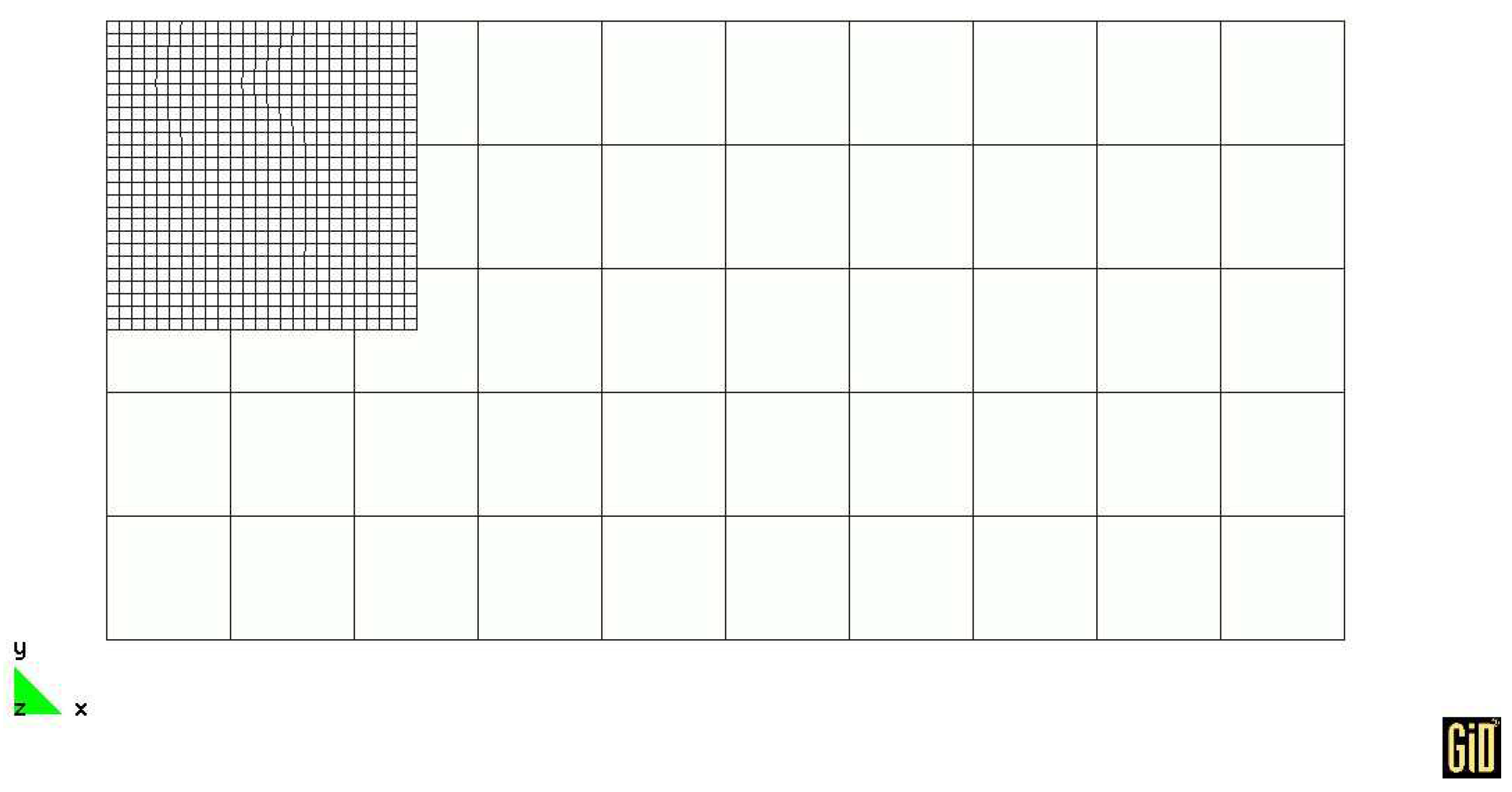
A rectangular element is used in this experiment. In CGM, the fine grid is used in the local region where the crack is included, its mesh sizes are h = 1 8 and h = 1 16 , respectively (see Figure 2). After discretization, the algebraic equations are solved by the successive over-relaxation (SOR) iterative method. v n + 1 is the iterative solution between the coarse and fine grid, v n + 1 v n < ε is stopping condition ( ε = 1 e 5 ).
Calculate with the general finite element method again; uniform grids are applied; the mesh sizes are h = 1 8 and h = 1 16 , respectively. Choose A ( 1 4 , 1 4 ) , B ( 0 , 1 4 ) , C ( 1 4 , 1 4 ) , D ( 1 2 , 1 4 ) and E ( 3 4 , 1 4 ) as observation points. The error of general FEM and CGM on these points are shown in Table 1.

3.2. The Simulation of Laser Welding

Now, we shall apply the CGM algorithm to simulate the result of laser welding. Laser welding, using a laser beam of high energy density as a heat source, is a highly efficient and precise welding method [17].
For the weldment to be symmetrical, the weld joint must be on the axis of symmetry of the weld bit. Therefore, the result of the welding process can be analyzed on the hemi-section. So numerical analysis is practiced on a 2 D axisymmetric cylinder coordinate system.
Coarse grid size is 20 × 10 mm, divided into 50 elements; fine grid is 5 × 5 mm in 625 elements, see Figure 3:
For the transient heat transfer problem, according to the Fourier heat transfer theorem and the energy conservation theorem, the heat-conduction control equation can be described as:
ρ c T t = · ( λ T ) + q
In the equation, ρ is the density of material, c is the specific thermal capacity of the material, λ is the heat conductivity of the material, T is the temperature, q is the heat source.
The Navier-Stokes equation is the partial differential equation that generally governs the flow phenomenon:
ρ u t + ρ u · u + p = μ Δ u + ρ f · u = 0
where t is the time, x is the position vector in the Cartesian coordinate system, respectively; u = u ( x , t ) , p = p ( x , t ) , ρ and μ denote velocity vector, pressure, density and kinematic viscosity coefficient, respectively. f is the force.
In order to avoid the difficulties in computation, when we compute the approximate solution of the Navier-Stokes equations, the operator splitting method (OSM) is used. Here, the physical process described by the equations is decomposed into three processes: a diffusion process, a pressure-projection term and a convection process, and the finite element equation is established [18].
The governing equation corresponding to the Fluid Diffusive Part is as follows:
ρ u t = μ Δ u + ρ f
The Pressure-projection part is as follows:
ρ u t + p = 0 · u = 0
The corresponding governing equation of the fluid diffusive part is:
ρ u t + ρ u · u = 0
The diffusion Equation (11) is solved first. The OSM algorithm is described as follows:
step 1: u n + 1 3 = u n + μ Δ u n + 1 3 + ρ f n Δ t
step 2:
u n + 2 3 = u n + 1 3 + p n + 1 Δ t · u n + 2 3 = 0
step 3: u n + 1 = u n + 2 3 u n + 2 3 · u n + 2 3 Δ t
The initial condition is as follows: when t = 0 , the workpiece has a uniform primary temperature. The environmental temperature is commonly chosen as 27 °C.
In order to simulate the typical molten pool of high energy beam welding more precisely, which is in the shape of a nailhead with a large aspect ratio, the Rotary-Gauss body heat source model is established. The mathematical formula of the Rotary-Gauss body heat source model is as follows: ref. [19]:
q ( x , y , z ) = c s Q π H 1 1 e 3 exp 3 c s ln ( H z ) x 2 + y 2
c s = 3 R 0 2 is the concentration coefficient of the shape of the heat source, R 0 is the opening radius of the heat source, H is the height of the heat source, Q is the heat source power. See Figure 4.
The time step is 1 ms and the heating time is 10 ms. Calculate by CGM. Rectangular element is used. The fine grid’s result can be see in Figure 5, Figure 6 and Figure 7. The horizontal coordinate of Figure 5 and Figure 6 consists of the time step and the vertical coordinate is the solder joint temperature.
We have selected the welding simulation graphs from the simulation software for two different time steps, see Figure 7. As can be seen in Figure 7, the left side graph is the temperature graph of the interface at the first time step and the right side is the temperature graph at the 22nd time step. Comparing the two plots, it can be seen that the MCG algorithm solves the soldering problem well.
Calculate using the gener/[-al finite element method. Uniform grids are applied, with subdivision scales the same as the fine grid of CGM. See the temperature result of the solder joint in Table 2.

4. Conclusions

In this paper, we introduced the CGM, an improved FAC method. From the numerical examples, we can see that, because the fine grid only generates on the local singular domain, the grid number and nodal number are reduced effectively, which causes the labor of calculation to be reduced, saving the system resource and calculating time considerably. Thus, complex problems can be solved on low-configuration machines. This method improves the accuracy at the local singular domain, and the local solution can be obtained effectively. Compared with the global fine grid, the CGM`s accuracy nearly reached the FE analysis accuracy of the global fine grid. However, there is a massive order of magnitude difference in the labor of calculation between them. In CGM, L c and L f can be different operators. It is more suitable to solve more complex problems than other methods. The iterative number is reduced in CGM. When operators L c and L f satisfy L c = L f , iteration is convergent in one iterative step. When treating the problem of the local singular domain being moved to the global domain relatively, it is important to note that the two sets of grids are not nested. However, it is still possible to move a fine grid with its corresponding one by adding a control Fortran program.
The method can effectively improve the convergence speed of the iterative algorithm through the conversion between coarse and fine meshes, in addition to improving the accuracy of the numerical solution. Future research will focus on how to design a fast and stable composite mesh method to reduce the computation time and improve the numerical accuracy further.

Author Contributions

Methodology, H.Y.; Writing—original draft, H.Y.; Writing—review & editing, Y.X.; Visualization, Y.X. All authors have read and agreed to the published version of the manuscript.

Funding

This work is supported by the National Natural Science Foundation of China (No. 11901098) and the Natural Science Foundation of Fujian Province, China (No. 2020J05034).

Data Availability Statement

Data will be made available on reasonable request.

Conflicts of Interest

The author declares that they have no conflict of interest.

References

  1. Furzeland, R.M.; Verwer, J.G.; Zegeling, P.A. A numerical study of three moving-grid methods for one-dimensional partial differential equations which are based on the method of lines. J. Comput. Phys. 1990, 89, 349–388. [Google Scholar] [CrossRef] [Green Version]
  2. Chen, Y.; Chen, L.; Zhang, X. Two-Grid method for nonlinear parabolic equations by expanded mixed finite element methods. Numer. Methods Partial. Differ. Equations 2013, 29, 1238–1256. [Google Scholar] [CrossRef]
  3. Williamson, D.L. The evolution of dynamical cores for global atmospheric models. J. Meteorol. Soc. Jpn. 2007, 85, 241–269. [Google Scholar] [CrossRef] [Green Version]
  4. Chesshire, G.; Henshaw, W.D. Composite overlapping meshes for the solution of partial differential equations. J. Comput. Phys. 1990, 90, 1–64. [Google Scholar] [CrossRef]
  5. Mak, H.W.L. Improved Remote Sensing Algorithms and Data Assimilation Approaches in Solving Environmental Retrieval Problems; Hong Kong University of Science and Technology: Hong Kong, China, 2019. [Google Scholar]
  6. Takemura, K.; Ishioka, K.; Shige, S. Development of a non-hydrostatic atmospheric model using the Chimera grid method for a steep terrain. Atmos. Sci. Lett. 2016, 17, 109–114. [Google Scholar] [CrossRef] [Green Version]
  7. Tao, L.; Jimin, S.; Zhenbao, L. Domain Decomposition Methods—New Numerical Techniques for Solving PDE; Science Press: Beijing, China, 1992. (In Chinese) [Google Scholar]
  8. Mote, C.D. Global-local finite element. Int. J. Numer. Methods Eng. 1971, 3, 565–574. [Google Scholar] [CrossRef]
  9. Zhu, K.; Zheng, X.; Zhang, C. The behavior of interlocked ortho-grid composite sandwich structure subjected to low-velocity impact. Compos. Struct. 2023, 304, 116399. [Google Scholar] [CrossRef]
  10. Lebon, F. Two-grid method for regularized frictional elastostatics problems. Eng. Comput. 1995, 12, 657–664. [Google Scholar] [CrossRef]
  11. Cai, Z.; McCormick, S. On the accuracy of the finite volume element method for diffusion equations on composite grids. Siam J. Numer. Anal. 1990, 27, 636–655. [Google Scholar] [CrossRef]
  12. Xu, J.; Park, U. The auxiliary space method and optimal multigrid preconditioning techniques for unstructureed grids. Computing 1996, 56, 215–235. [Google Scholar] [CrossRef]
  13. Xu, J.; Zhou, A. Local and parallel finite element Algorithms based on two-grid discretizations. Math. Comp. 2000, 69, 881–909. [Google Scholar] [CrossRef] [Green Version]
  14. Liang, G. FEPG User’s Manual; 2008.
  15. Beijing FEGENSOFT Co., Ltd. FEPG Reference Manual—Finite Element Method Based on FEPG; Beijing FEGENSOFT Co., Ltd.: Beijing, China, 2005. [Google Scholar]
  16. Chikin, P.; Chinbo, L.; Tsimin, S. On the computational aspects of the fast adaptive composite grid method for solving second order elliptic equations. J. Numer. Methods Comput. Appl. 1994, 4, 293–298. [Google Scholar]
  17. Guoming, H.; Jian, Z.; Jian Qang, L. Dynamic simulation of the temperature field of stainless steel laser welding. Mater. Des. 2007, 28, 240–245. [Google Scholar] [CrossRef]
  18. Shui, W.; Nielsen, M.P. Solving Navier-Stokes equation by mixed interpolation method. J. Southeast Univ. 2006, 22, 93–95. [Google Scholar]
  19. Su, W.; Haiyan, Z.; Yu, W. A new model in numerical simulation of high energy beam welding. Trans. China Weld. Inst. 2004, 25, 91–94. [Google Scholar]
Figure 1. Composite grid model.
Mathematics 11 03385 g001
Figure 2. Composite Grid (mesh size of fine grid h = 1 8 ).
Mathematics 11 03385 g002
Figure 3. Composite Grid of weldment.
Mathematics 11 03385 g003
Figure 4. Rotary-Gauss body heat source model.
Mathematics 11 03385 g004
Figure 5. The temperature curve of the Solder Joint.
Mathematics 11 03385 g005
Figure 6. The temperature curve of the Solder Joint.
Mathematics 11 03385 g006
Figure 7. The changing of weldment in local region.
Mathematics 11 03385 g007
Table 1. The error of two methods ( · ).
Grid TypeGeneral FEMCGM
Genuine SolutionMesh SizeErrorMesh Size of Fine GridError
A 0.00469 A 0.00458
B 0.00790 B 0.00779
1 8 C 0.00801 1 8 C 0.00790
A 0.2275 D 0.00229 D 0.00229
B 0.3536 E 0.00070 E 0.00070
C 0.5493 A 0.00170 A 0.00149
D 0.7277 B 0.00309 B 0.00298
E 0.8777 1 16 C 0.00230 1 16 C 0.00229
D 0.00081 D 0.00079
E 0.00020 E 0.00020
Table 2. The temperature field results of two methods.
Time Step121015304560
Temperature
T 1 (general FEM)471.982887.1212949.382184.16880.003443.312352.915
T 2 (CGM)474.085892.3132971.352183.30867.932439.152350.282
| T 2 T 1 T 1 | 0.0044560.0058530.0074490.0003940.0137170.0093840.007461
Disclaimer/Publisher’s Note: The statements, opinions and data contained in all publications are solely those of the individual author(s) and contributor(s) and not of MDPI and/or the editor(s). MDPI and/or the editor(s) disclaim responsibility for any injury to people or property resulting from any ideas, methods, instructions or products referred to in the content.