Abstract
An automated Condition Monitoring (CM) and real-time controlling framework is essential for outdoor mobile robots to ensure the robot’s health and operational safety. This work presents a novel Artificial Intelligence (AI)-enabled CM and vibrotactile haptic-feedback-based real-time control framework suitable for deploying mobile robots in dynamic outdoor environments. It encompasses two sections: developing a 1D Convolutional Neural Network (1D CNN) model for predicting system degradation and terrain flaws threshold classes and a vibrotactile haptic feedback system design enabling a remote operator to control the robot as per predicted class feedback in real-time. As vibration is an indicator of failure, we identified and separated system- and terrain-induced vibration threshold levels suitable for CM of outdoor robots into nine classes, namely Safe, moderately safe system-generated, and moderately safe terrain-induced affected by left, right, and both wheels, as well as severe classes such as unsafe system-generated and unsafe terrain-induced affected by left, right, and both wheels. The vibration-indicated data for each class are modelled based on two sensor data: an Inertial Measurement Unit (IMU) sensor for the change in linear and angular motion and a current sensor for the change in current consumption at each wheel motor. A wearable novel vibrotactile haptic feedback device architecture is presented with left and right vibration modules configured with unique haptic feedback patterns corresponding to each abnormal vibration threshold class. The proposed haptic-feedback-based CM framework and real-time remote controlling are validated with three field case studies using an in-house-developed outdoor robot, resulting in a threshold class prediction accuracy of 91.1% and an effectiveness that, by minimising the traversal through undesired terrain features, is four times better than the usual practice.
Keywords:
AI; condition monitoring; vibration; vibrotactile haptic feedback; wearable device; IMU; current sensor; 1D CNN; outdoor mobile robot; remote control; operational safety MSC:
68T40; 68T01; 68T07; 93C85
1. Introduction
The rapid developments of robotics fundamental techniques and Artificial Intelligence (AI) models have enabled versatile outdoor robots to reduce human efforts in performing dull, dirty, and repetitive tasks, thereby resolving labour shortage issues and workplace-related safety infection risks. There is a vast market demand for diverse outdoor applications such as pavement sweeping, fumigation and fogging, landscaping, inspection, logistics, and security. Based on ABI Research, an expected shipment volume of outdoor mobile robots is 350,000 units by 2030, compared to 40,000 units in 2021 [1]. Much research has been published on autonomous performance improvement to fit the outdoor environment; for example, environmental perception [2], visual navigation [3], path planning [4], localisation [5], motion control [6], and pedestrian safety [7]. Though the system degradation in an outdoor robot is faster due to its exposure to extreme terrain and weather changes, focus on Condition Monitoring (CM) studies are still not commonly used to assess health states and terrain-related flaws, causing accelerated deterioration and potential hazards. The above mentioned research works are mainly focused on performing operations autonomously. However, there is still a long way to go to make these robots operate without human guidance by considering the open, hostile, and unsafe outdoor environment. Also, local regulations and certifications are to be checked and complied with for deploying robots autonomously on public pavements [8].
In this context, shared autonomy, where the robot’s autonomous system and operator input work collaboratively to make decisions and achieve common goals [9,10], is a safe and feasible option for outdoor robot deployment. Also, studies on haptic-feedback-based motion control of robots [11,12,13,14] have enabled effective remote operation. An environment-independent sensor selection for data acquisition and a fast and accurate classifier model is crucial for real-time CM frameworks for the outdoor environment. There are numerous AI-enabled and vibration-based terrainability studies for outdoor robots using different sensors to classify tile, stone, sand, asphalt, grass, and gravel [15,16,17,18,19], which will help to decide the traversability of the robot, but there is not a proper CM approach for assessing the health condition of the robot and level of terrain-induced concerns that accelerate system degradation. Hence, an automated CM and feasible remote controlling framework involving a shared autonomy and haptic feedback system is imperative for outdoor robots assisting in either stopping or minimising the exposure to extreme terrain conditions based on the internal health and external terrain states of the robot. Towards this effort, this paper proposes and discusses vibration-based anomalies prediction using Inertial Measurement Unit (IMU) and current sensors data and a 1D Convolutional Neural Network (1D CNN) as the classifier, along with real-time robot control, by developing a wearable vibrotactile haptic feedback system, assuring productivity and operational safety in outdoor mobile robots.
1.1. Problem Statement
The deployment of mobile robots in a dynamically changing and unsafe outdoor environment is still a challenging problem, and condition monitoring studies performed to assess the health conditions of the robot and the uneven terrain features affecting accelerated deterioration is an unexplored research area, resulting in catastrophic failure, a high maintenance cost, unexpected downtime, operational hazards, and customer dissatisfaction. The aforesaid terrainability studies may help the last mail delivery or outdoor security robots in path planning, avoiding terrain-related flaws. However, in fumigation, lawn mowing, and pavement sweeping applications, the robot is supposed to cover a given area for the intended function. In particular, traversing through grass fields is more challenging where exteroceptive techniques are impractical as most ground-level imperfections are grass-covered. The system also degrades naturally due to continuous usage, even when deployed in a plain area, or there may be accelerated deterioration due to the terrain flaws depending on the workspace deployed. Hence, periodic maintenance is not advised for outdoor robots. The manual procedure is generally practised to assess the robot’s condition and how good the given area is for deployment, which is labour-oriented and results in high maintenance costs. Hence, a study on automated CM strategy for outdoor mobile robots is vital for addressing this problem.
Selecting proper sensors to extract the characteristics of both system degradation and terrain-induced concerns is critical, and it should be environment-independent for outdoor robots. Vibration is widely accepted for fault detection, and most of the studies used an IMU sensor for vibration-indicated data modelling based on the change in linear and angular motions. However, sometimes robots are stopped by ground-level obstacles where no abnormal vibrations are noticed, so more suitable sensors must be integrated and explored. A fast and computationally low-cost neural network model with higher prediction accuracy is mandated for real-time applications to avoid false positive actions. The shared autonomy and haptic-feedback-based approach is a feasible approach for CM in outdoor robots; however, the current studies are mainly focused on controlling robot arms, motion control, and safe navigation, avoiding obstacles in mobile robots and drones in their heading direction, and do not explore CM applications in outdoor mobile robots. Since CM covers internal and external factors and different threshold levels are involved, a multi-level haptic feedback patterns system is essential for effectively monitoring and controlling the robot. The proposed study analyses the abovementioned problems for a feasible solution for CM applications in outdoor mobile robots.
1.2. Related Works
Abnormal vibration is an indicator of system failure; hence, many fault detection and prognosis studies are conducted based on vibration-indicated data collected through suitable sensors, mainly accelerometers [20,21,22]. The advent of deep learning models, especially 1D CNN, is found to be accurate in extracting the unique features in order to classify and assess the severity of anomalies, and they are used for real-time applications due to their simple structure, low computational complexity, and easy deployability [23]. The vibration and 1D-CNN-based works are common for the CM and fault assessment of machine components [24,25], structural systems [26], and industrial robots [27]. Other CM and fault diagnosis works for industrial robots include minimising downtime in a wafer transfer robot [28], failure prediction in a packaging robot [29], and a safe stop for a collaborative robot [30]. However, such CM works are not extended for outdoor mobile robots, though a great research scope using the typical onboard sensors and a necessity because of their vast market demand and safety. Towards this CM effort, we introduced two vibration-based approaches in previous works for indoor mobile robots, considering both internal and external sources of vibration. In an IMU sensor-based work [31], the change in angular velocity and linear acceleration data due to vibration sources is mainly modelled as vibration data and, in the second work, a monocular camera sensor [32] is used and the change in optical flow 2D vector displacement data is modelled as vibration-indicated data for training. In both works, a 1D CNN was adapted as a classifier and compared with other models, such as a Support Vector Machine (SVM), Multilayer Perceptron (MLP), Long Short-Term Memory (LSTM), and CNN-LSTM, showing better accuracy and inference time.
The CM studies for outdoor robots are more challenging and unexplored, and the existing studies are limited to terrain classification using different sensors and AI models to assess traversability only; for instance, a terrain type study using IMU and a Probabilistic Neural Network (PNN) for autonomous ground vehicles in [15], classifying asphalts, gravel, mud, and grass. A terrain feature study based on texture-based descriptors is conducted in [17] using a camera and Random Forest (RF) classifier. A sensor fusion approach using IMU and camera is used in [18] for terrain classification, adapting an SVM as the classifier and mentioning that a faster model is needed for real-time application. A 3D LiDAR sensor is used for traversability analysis in [19] with the positive naive Bayes classifier by defining the feature vectors with different dimensions. Regarding the wheel–terrain tough interactions due to ground-level imperfections and obstacles, a higher torque is applied to overcome the flaws and, naturally, a higher current consumption occurs. However, the current sensors are more used for energy efficient strategy studies in mobile robots [33,34] rather than CM applications, except an earlier study in [35] for fault diagnosis in motor-driven equipment by monitoring current readings.
The vibrotactile haptic feedback approach is used in many systems, conveying information to the user or operator through vibration patterns, mainly for human health monitoring or assistance, by developing wearable devices, such as the health monitoring of an offshore operator in [36] and wheelchair navigation for disability people in [37]. Recently, these techniques have been applied to remotely controlled industrial and mobile robots. For instance, haptic-feedback-based teleoperation using a Phantom Omni haptic feedback master device and a 6-DOF robot arm was used with a force sensor as a slave, enabling the operator to adjust the position and direction of the arm safely from a distance based on the distance from the haptic feedback to the manipulator [38], and a similar study was conducted in [39] to stop the manipulator avoiding any collision. An inexpensive electro-tactile-based haptic feedback method is presented in [40] for obstacle avoidance in a cluttered workspace of a teleoperated robot arm. A wearable hand gesture recognition and vibrotactile system is developed in [41] to control drone navigation, where the obstacle information in the heading direction is fed back to the operator. A haptic feedback and shared autonomy-based teleoperation for the safe navigation of mobile robots is explained in [11], where obstacle range information is fed back to the operator as a force through a haptic probe. Similar force feedback studies for mobile robots were conducted, including [12,13,14]. These haptic-feedback-based works are mainly undertaken for indoor robots for smooth navigation and avoiding obstacles in the heading direction. However, to our knowledge, there are no such works for CM applications in outdoor robots, feeding back the system deterioration stage and terrain-related features to ensure the robot’s health and operational safety.
1.3. Contributions
- 1.
- An unexplored vibration-based Condition Monitoring (CM) framework is introduced for outdoor mobile robots considering both the system deterioration state and uneven terrain features.
- 2.
- Eight abnormal states are identified for an outdoor wheeled robot set at different threshold levels for CM in view of real-world cases.
- 3.
- The vibration-indicated data are modelled based on IMU and current sensors data, which complement each other for system-generated/degraded and wheel–terrain interaction-related robot behaviour.
- 4.
- A simple 1D CNN-based model is structured for the fast, accurate, and computationally low cost enabling of the real-time prediction of vibration threshold classes.
- 5.
- A novel wearable vibrotactile haptic feedback device architecture is presented for CM applications in outdoor robots and configured with unique tactile feedback patterns for each threshold class.
- 6.
- The real-time field case studies conducted using an in-house-developed outdoor fumigation robot show the impacts of the proposed research framework, enhancing the robot’s health and operational safety.
- 7.
- The proposed AI-enabled vibrotactile feedback-based CM framework for real-time remote controlling is the first of its kind for outdoor mobile robots.
The remainder of this paper is structured as follows. Section 2 presents an overview and methodology of the proposed work. Section 3 elaborates on the framework evaluation and results. Section 4 explains field case studies conducted to validate the proposed method for real-time application, and Section 5 concludes with a summary of the work.
2. Overview of the Vibrotactile Feedback-Based Condition Monitoring Framework
An overview of the proposed vibrotactile feedback-based condition monitoring and real-time remote controlling framework for health monitoring and avoiding uneven terrain features in outdoor mobile robots is depicted in Figure 1. It mainly consists of two systems: a health status and uneven terrain-induced threshold classes publishing system at the robot side and a haptic-feedback-based real-time remote controlling system using a vibrotactile haptic feedback device at the operator side. The data transfer between the robot (publisher) and the vibrotactile device (subscriber) is accomplished by setting a topic through a Message Queuing Telemetry Transport (MQTT) broker protocol. The design and methodology followed to develop and test these two systems for the proposed framework are elaborated as follows.
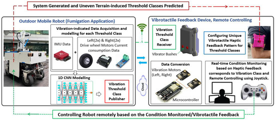
Figure 1.
Overview of the vibrotactile feedback-based condition monitoring and remote controlling.
2.1. Predicting the Anomalous Cases for Condition Monitoring—Robot Side
This section explains the methodology followed for identifying and predicting the anomalous cases at the robot side, covering the details of the outdoor robot platform used for the data acquisition and field trials, the system-generated/deteriorated and uneven terrain-induced vibration threshold classes, vibration-indicated data modelling, and the 1D CNN model structured for classification and prediction.
2.1.1. Outdoor Mobile Robot Test Platform
An in-house-developed wheeled outdoor mobile robot is used in this study for vibration-indicated data acquisition and real-time field case studies. The base platform of this robot is designed with interchangeable payloads for outdoor applications such as fumigation (pest control), pavement sweeping, and lawn mowing by mounting a sprayer with a tank assembly, sweeping brushes, and grass-cutting wire module, respectively. Here, we used the fumigation robot as it is intended to travel on both pavements and grass fields, exposing maximum undesired terrain features, and is hence an ideal test platform for this study. The size of the robot is 1.6 (L) × 0.85 (W) × 1 (H) m and it has an approximate weight of 300 Kg. The robot’s locomotion unit consists of four hub wheel motors of 250 W and steering motors of 100 W power, and the wheel size is 38 (outer diameter) × 15 (width) cm. An omnidirectional mobility is designed with independent steering drive wheels enabling better manoeuvrability. The robot is built with a robust chassis using the welding of stainless-steel sections, plates, shafts, and brackets for mounting all critical sub-assemblies and sensors, including a double wishbone suspension system to fit driving for outdoor applications. A 300 Ah 48V DC Lithium iron phosphate (LFP) battery is used to power the system and payloads. An Industrial PC Anewtech IPC970-10WF5E1A is integrated for entire operation and data storage. The Robot Operating System (ROS) middleware in the Ubuntu Noetic operating system is used to execute all communications. A TP-Link LTE 4G Router is added for remote monitoring and control, establishing Internet and wireless networking.
A shared autonomy framework is executed; hence, the robot’s autonomous behaviour is combined with human input as needed to monitor and control the robot, assuring the robot’s health and operational safety. The onboard computer processes a low-level autonomy stack using the perception sensors integrated to avoid large obstacles. The sensors include four ultrasonic sensors (UCC4000) mounted at four corners of the robot and two 2D LiDARs (SICK TIM581) mounted at the front and rear sides. A stereo camera (ZED 2) is mounted at the front towards the heading direction. For live streaming, four cameras are mounted: one main camera facing towards the heading direction, one at the rear side for any reverse motion, and the other two cameras at the left and right sides. This shared autonomy framework integrated into this fumigation robot was based on the previous works from our research lab [10], and a briefing of this shared autonomy framework is as follows. The four ultrasonic sensors detect obstacles, including transparent glass walls (when the robot traverses nearby buildings) and moving objects at all sides. The two 2D LiDAR sensors enable the robot to mainly detect any prominent cliffs, kerbs, or steps. The stereo camera detects the presence of pedestrians, bicycles, animals, and vehicles at the front, and measures pedestrian density as well. The four cameras help with live streaming. Additionally, a decision-making process based on multi-layer fuzzy logic is integrated into the robot as additional safety layers, considering the operator’s attention level and switching the operation modes, accordingly avoiding hazardous events. However, this is applicable only for the large obstacles in the heading direction of the robot, and any unseen and undetected ground-level obstacles are still harmful to the robot’s health and operational safety. The fumigation outdoor robot, as explained, used as a test platform in this study, is shown in Figure 2, including the perception sensors integrated for shared autonomy. Depending on the remote location, the human–robot interface/shared autonomy layer is connected through a network protocol, either using a local area network or cloud computing.
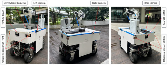
Figure 2.
Shared autonomy integrated outdoor fumigation robot test platform.
2.1.2. Vibration Threshold Classes for Condition Monitoring
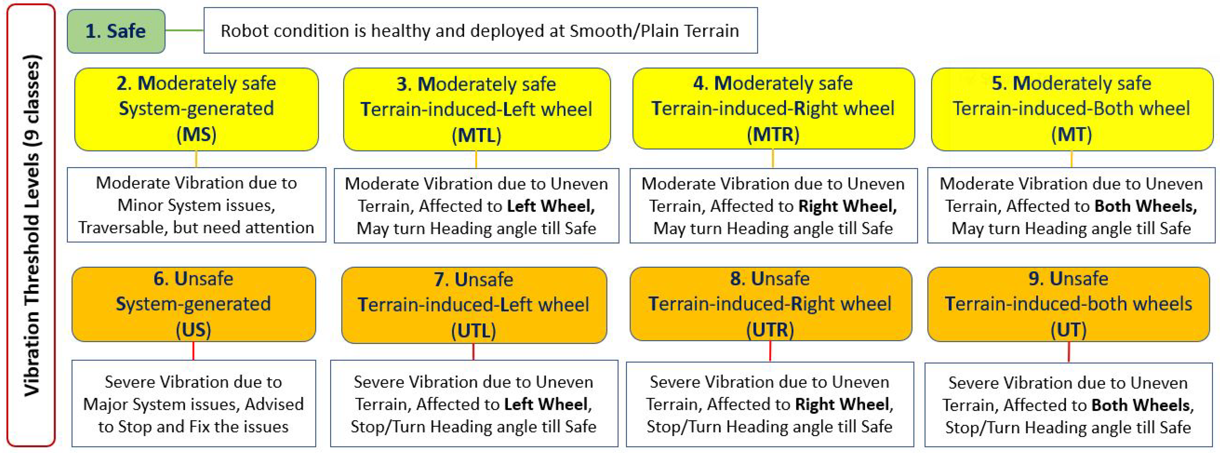
A mobile robot produces unusual vibrations as early symptoms of failure and potential hazards. The sources of such vibrations could be due to internal system issues like component deterioration, wear and tear, loose assembly, and an unbalanced structure, or external factors like uneven terrain and undetected ground-level small obstacles/features. Here, the severity of vibration depends on the various levels of such internal and external factors. Hence, a vibration threshold level-based classification used to distinguish the vibration sources and their acceptance assessment is essential to trigger prompt and proper corrective or maintenance action. For example, if the robot’s vibration is moderate, close attention is needed to proceed or change the heading direction. Suppose that the vibrations are severe due to internal or external factors: the operator should stop and fix the issues as soon as possible or change the heading direction to avoid ground-level obstacles and hazards. Hence, this study proposes nine vibration threshold classes for condition monitoring suitable for a four-wheeled outdoor mobile robot by considering both system-generated vibrations due to internal concerns and terrain-flaws-related external circumstances, namely Safe (no action required), Moderately safe due to System-generated (MS), Moderately safe due to Terrain-induced Left wheels affected (MTL), Moderately safe due to Terrain-induced Right wheels affected (MTR), Moderately safe due to Terrain-induced where both Left and Right wheels are affected (MT), Unsafe due to System-generated (US), Unsafe due to Terrain-induced Left wheels affected (UTL), Unsafe due to Terrain-induced Right wheels affected (UTR), and Unsafe due to Terrain-induced where both Left and Right wheels are affected (UT). Here, the MS class need to be kept in view to ensure that the condition is not worsening. The MTL, MTR, and MT classes need attention while proceeding or the heading direction may change. For the US class, the robot should be stopped and the issues should be fixed with proper maintenance actions. For the UTL, UTR, and UT classes, it is better to stop and change the heading angle and proceed only if it is safe. These nine vibration threshold classes tested and validated for condition monitoring in outdoor robots are depicted in Figure 3.
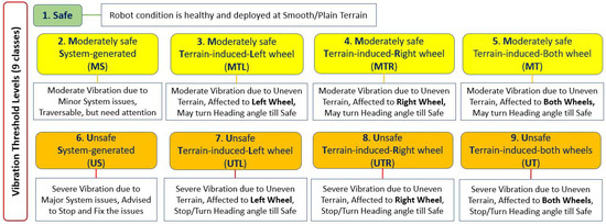
Figure 3.
Vibration threshold classification for condition monitoring.
2.1.3. Vibration-Indicated Dataset Modelling
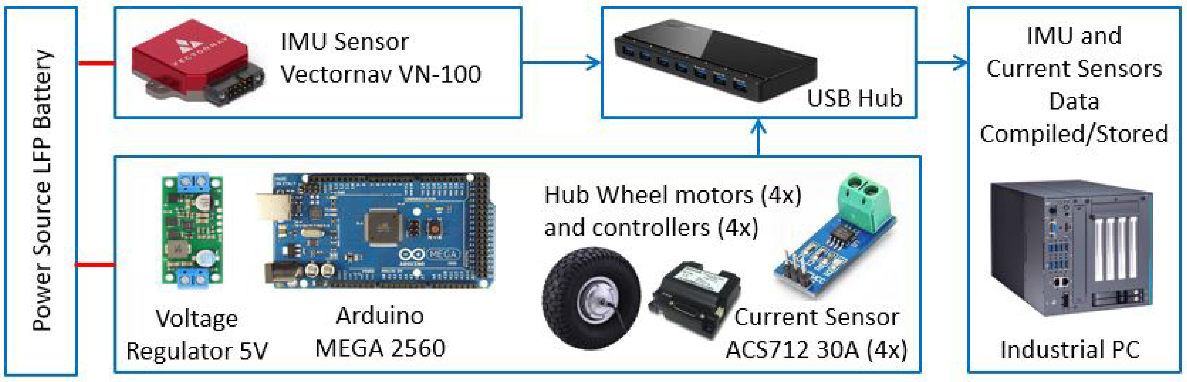
A wheeled outdoor mobile robot vibrates at different rates linearly or in angular motion (roll, pitch, yaw) due to being system-generated or terrain-induced, as explained in the previous section. Such abnormal movements of the robot could be assessed through IMU sensor data. Sometimes, the robot may not show an apparent vibration/angular motion when stuck with ground-level obstacles; instead, it keeps trying to overcome the obstacle, resulting in a higher torque required and higher current consumption. Hence, adding the current consumed data from each wheel motor will enhance the terrain-related threshold classes assessment specific to the left or right side affected for corrective action. Thus, these heterogeneous IMU and current sensors data support filling the gaps of individual sensors in extracting the relevant vibration-affected features. In this study, we used the onboard Vectornav VN-100 IMU sensor to extract the rate of the linear and angular motion of the robot at different vibration threshold classes, i.e., linear acceleration and angular velocity, from the accelerometer and gyroscope integrated with IMU. An ACS712 current sensor module is integrated with each wheel drive motor to tap the current consumption using an Arduino Mega 2560 microcontroller, enabling better prediction accuracy for terrain-induced classes specific to left and right. The calculated angular acceleration from the angular velocity data is added for further dataset strengthening. These proprioceptive sensors do not depend on each other and are unaffected by the environment or light conditions, facilitating higher-accuracy prediction. As the robot locomotion is controlled by four independent steering wheels (two drive wheels at both the front and rear) with holonomic mobility, the average current value of the front-left wheel motor and rear-left wheel motor is recorded as the left current value, and similarly for the Right. The IMU current sensors data acquisition scheme is depicted in Figure 4.
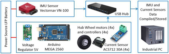
Figure 4.
Dataset acquisition scheme using IMU and current sensors.
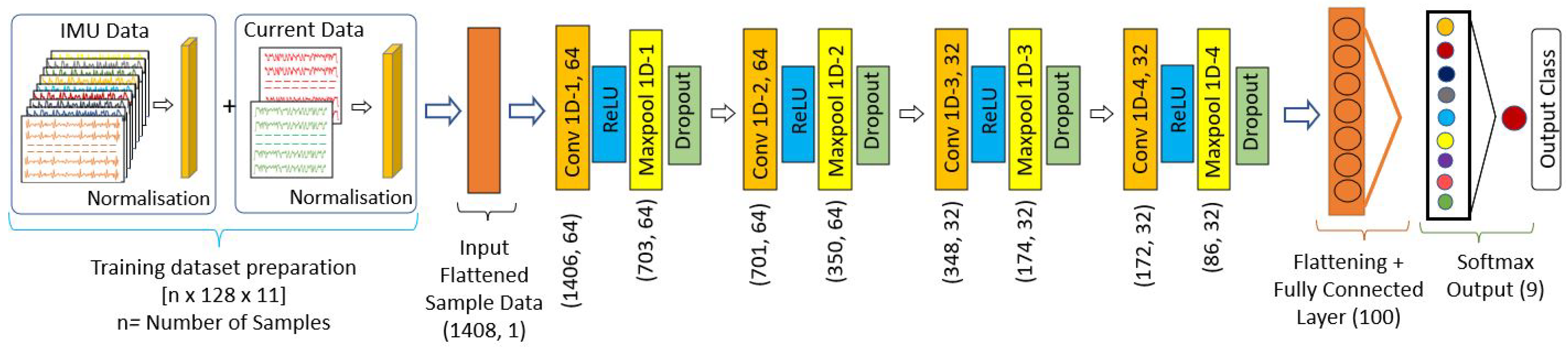
In this work, the vibration-indicated data (Vibdata) are the changes in the linear acceleration, angular velocity, angular acceleration measured through the IMU sensor, and data of the average current consumed by left-side pair motors and right-side pair motors measured using the current sensors, due to the various vibration threshold classes, which is modelled and represented as in (1). Here, the two types of sensors used have different behaviour; hence, the sequential data subscription rate is critical to represent all data recorded for the particular class in the given period. This is assured by setting the IMU subscription rate at 80 Hz and lowering the delay in the Arduino program to the same rate as the current sensor data subscription. It also confirmed that the total number of samples data collected at any particular time is the same. The data features for linear acceleration, angular velocity, and angular acceleration are recorded in three axes—a total of nine data from IMU and two data features from the robot’s left and right-side motors pair—hence, a total of 11 data features are used. Further, each data feature is compiled with 128 temporal data, forming one sample datum for training acquired in 1.6 s. Hence, a sample datum is an array of [128 × 11] as represented in (2). The IMU and current sensors data are normalised into standard scale without losing information for better convergence during training, and then compiled into an array of [n × 128 × 11] as training and evaluation datasets for each class for the 1D CNN training, where n is the total number of samples.
2.1.4. 1D CNN Modelling for Training and Prediction of Threshold Classes
A simple structured 1D-CNN-based model is proposed to train threshold classes for fast, accurate prediction and real-time CM applications. The model follows the convolution operations on data vectors using a nonlinear activation function that convolves the input vector to the output layer using a filter vector, as in Equations (3) and (4) [42]. Here, x (of length N) is the input data vector, (of length L) is the filter vector, the term b is the bias to the best fit for given data, and c is the output layer (of length N− L + 1). For detecting the key characteristics and reducing the number of parameters, a max pooling output vector d is added after convolution layers, where is the kernel size, u is a window function, and s is the filter moving stride over input vector c.
The dataset [128 × 11] prepared for each class is flattened into a 1D array [1 × 1408] to be fed into convolution layers. The CNN structure for this study is made simple with four layers, and uses sixty-four filters for the first two layers, and then thirty-two for the remaining. A convolution window (kernel) size of 3 is used for each layer. For effective learning of the non-linear vibration-indicated heterogeneous sensors data pattern, a Rectified Linear activation Unit (ReLU) is applied to each convolutional layer, followed by a max pooling layer with a stride size of 2, enabling a reduction in the computation time. To avoid over-fitting while training, a dropout layer is added at a rate of 0.2 for each layer. Finally, with a flattening function, the pooled feature maps are converted into a 1D array in the output layer, which predicts the multinomial probability of threshold classes. The proposed 1D-CNN-based model structure is illustrated in Figure 5.

Figure 5.
One-dimensional CNN model structure and data shape for training.
2.2. Vibrotactile Feedback System for Condition Monitoring and Remote Controlling—Operator Side
This section explains the vibrotactile haptic feedback device developed and the methodology followed to receive and convert the predicted abnormal classes to unique haptic feedback patterns corresponding to the abnormal threshold classes, enabling prompt actions by the remote operator.
2.2.1. Vibrotactile Haptic Feedback Device Architecture
A vibrotactile haptic feedback device is developed to understand the anomalous cases related to the robot’s system/deterioration level and uneven terrain features causing accelerated degradation or hazards, thereby switching the robot’s control to operator mode and taking necessary actions in real-time. Here, the anomalous cases are the eight abnormal threshold classes (MS, MTL, MTR, MT, US, UTL, UTR, and UT) identified and predicted by the robot (publisher). The haptic device comprises an ESP8266 ESP-12E microcontroller, two vibration modules/motors (DFR0440), a 9 V alkaline battery, a 5 V voltage regulator, and a power switch. A 3D-printed middle bracket for holding/guiding the components and top and bottom protective enclosures are used and fastened with screws. The DFR0440 vibration module is built with an Eccentric Rotating Mass (ERM) vibration motor; hence, the module vibrates when the motor shaft with offset mass rotates. The vibration modules are vertically guided independently and floated with low-tension compression springs. A hemispherical plastic bush is attached to each vibration module, acting as an actuator for tactile stimulation. The two vibration modules and the vibrator bushes named left and right also represent the robot’s left and right wheels in the cases of left- and right-wheel-induced vibration classes. The vibration modules stimulate based on the vibration pattern configured for each threshold class and effectively deliver tactile feedback to the operator through the left and right vibrator bushes. As it is a wearable device, various ergonomics and safety factors have been considered while designing the device; for instance, a compact and minimum overall size while at the same time keeping the left and right bushes as far as possible to distinct the two bushes’ feedback, a lower weight, being easy to wear with a single hand, being adjustable to fit with the operator’s upper arm size, and having no sharp corners, especially regarding the vibrator bushes, which are in contact with the operator, for mechanical safety. In addition, the electrical circuits and battery connection are carefully wired and isolated for electrical safety. The device is compact, with a size of 80 × 68 × 38 mm, and weighs 100 gm. A single armband with a velcro fastener is used to firmly hold the device with the remote operator’s upper arm, and the spring-loaded left and right vibrator bushes ensure contact with the operator. The design and assembly details of the haptic feedback device proposed for the CM application of an outdoor mobile robot are depicted in Figure 6.
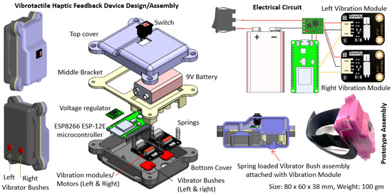
Figure 6.
Vibrotactile haptic feedback device architecture.
2.2.2. Vibrotactile Haptic Feedback Patterns for Threshold Classes and Encoding
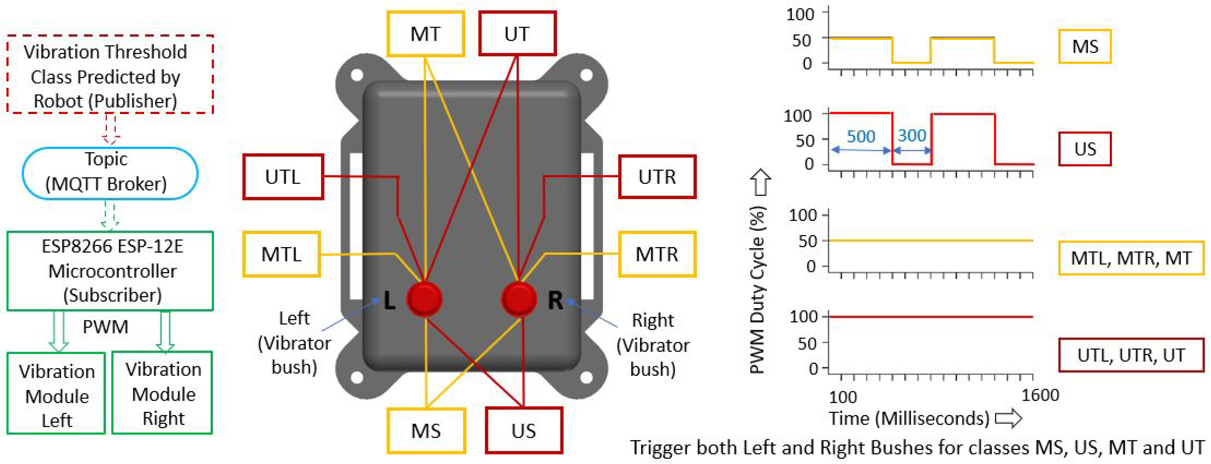
The vibration threshold classes predicted by the 1D CNN model at the robot side are published to a topic via MQTT Broker, which is subscribed by the microcontroller at the haptic feedback device. The vibrotactile feedback pattern for each threshold class should be easy to perceive and intuitive to avoid additional cognitive attempts from the operator. Hence, distinctive vibration feedback patterns are planned that correspond to each threshold class by changing the vibration intensity of the module (ERM speed), setting to ON/OFF and continuous ON modes, and utilising the left and right vibration modules/bushes. The vibration intensities of the module are set by changing the duty cycle of the Pulse Width Modulation (PWM) signal sent to the vibration module. The left, right, or both vibration modules will be stimulated for the terrain-induced classes specific to the affected left-, right-, or both-side wheels. For all Moderately safe classes (MS, MTL, MTR, and MT), the PWM duty cycle is set as 50% and, for all Unsafe classes (US, UTL, UTR, and UT), it is set to 100%, resulting in moderate and the highest vibration intensity, respectively. Further, to distinguish between system-generated and terrain-induced, the vibration pattern is set as ON and OFF mode for System-generated classes (MS and US) with an off time of 300 ms. And, for Terrain-induced classes (MTL, MTR, MT, UTL, UTR, and UT), the vibration mode is set as a continuous pattern. The predicted vibration threshold classes’ conversion to specific vibrotactile feedback patterns is illustrated in Figure 7. Here, 1.6 s is used for the vibration pattern, considering each prediction based on every new dataset.
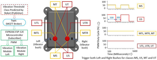
Figure 7.
Vibrotactile feedback patterns for abnormal threshold classes.
As there are a total of eight abnormal classes (excluding the safe class, which needs no action) in our proposed study, designing a unique pattern for each class was one of the challenges in the work, which we realised by the combination of the mechanical design of the haptic device, hardware, and software architecture. The mechanical design and hardware setup were made simple with only two actuators (left and right vibrator tactile bush/vibrator module) as more actuators/vibrator modules raise complexity in ergonomics and assessment. Similarly, the programming simplified the design by limiting the Pulse Width Modulation (PWM) duty cycles to only two settings (50% and 100%). Based on these minimum number of features/ parameters, the unique haptic feedback pattern for eight classes is made simple and intuitive.
In summary, for all Moderate classes (MS, MTL, MTR, and MT), the haptic feedback intensity (vibration intensity of the vibrator module/motor) will be moderate, and for the Unsafe classes (US, UTL, UTR, and UT) the haptic feedback intensity is set at maximum (not harmful) to distinguish between these two threshold levels. Further, the haptic feedback is set ON and OFF for the System-generated vibration MS and US classes (internal system degradation), i.e., the device will be OFF for 300 ms after a 500 ms feedback period. These vibration patterns designed are intuitive or need less learning effort; hence, the operator can easily make decisions based on this vibration intensity difference and ON/OFF vibration pattern configurations for the specific class.
As per the haptic feedback received through the vibrator bushes, the operator can trigger the corrective actions by changing the robot’s heading angle, moving left or right, thereby minimising the traversal through uneven terrain or planning to stop the robot if the robot persistently predicts unsafe classes either due to system-generated or terrain-induced flaws. The distinctive haptic feedback is evaluated, simulating the eight classes, and is tested by different users. No haptic feedback is programmed for safe class prediction.
3. Training and Evaluation of 1D-CNN-Based Threshold Class Prediction Model
This section composes data acquisition methods representing the nine classes based on the two heterogeneous sensors and their visual representation, followed by the 1D CNN model training for optimum performance and evaluation results.
3.1. Training Dataset Preparation for the Vibration Threshold Classes
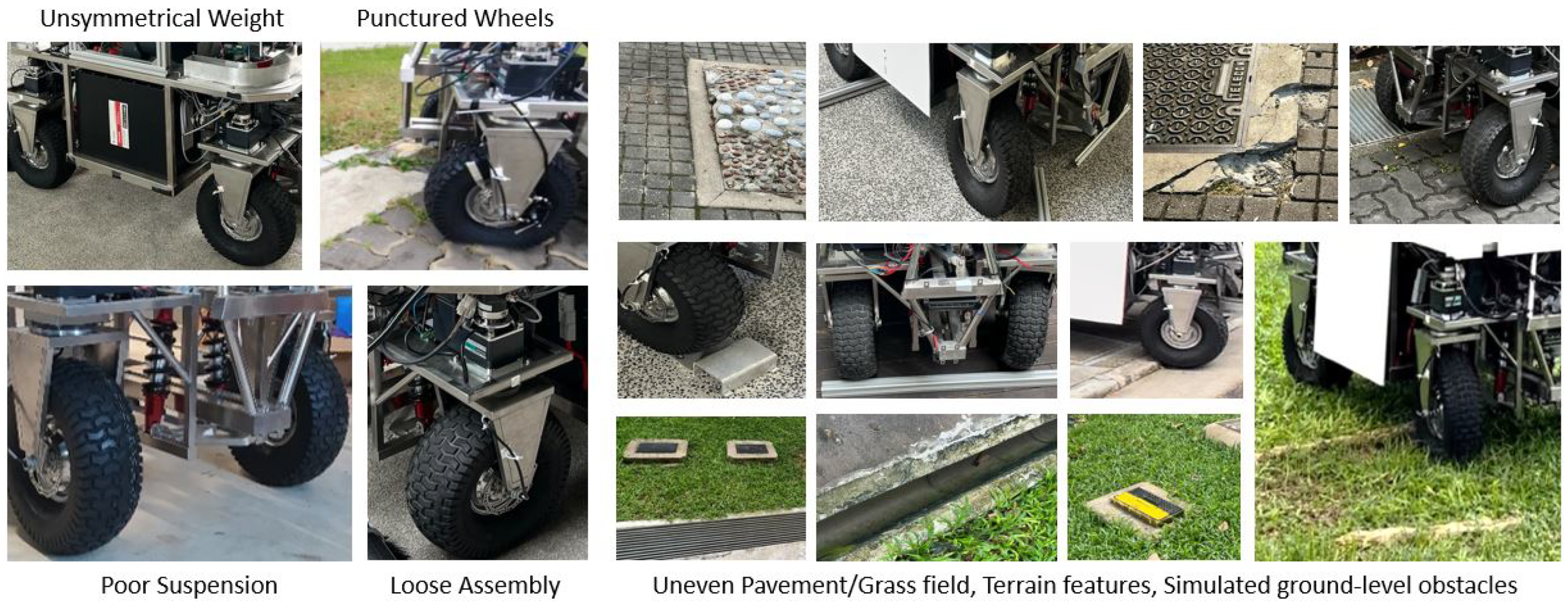
The data acquisition representing the nine classes for training the 1D CNN model, using the two heterogeneous sensors integrated with the fumigation robot, is critical. Hence, it is firstly confirmed that the Vectonav VN-100 IMU sensor and the four ACS712 30 A current sensors are mounted firmly with the chassis and wheel motors, and the data subscription rate (80 Hz) and dataset collection algorithm work properly, compiling the data in an array of [n × 128 × 11] as explained in Section 2.1.3. The robot’s linear speed is set at 0.3 m/s, which is the same as the operating speed, and the robot is driven in a zig-zag pattern while collecting the training data. For the safe class dataset preparation, the robot is tested, assuring good health, and is operated on plain and well-maintained pavements and grass fields, where no apparent vibrations are observed. The dataset collected during this trial is saved and labelled as the safe class. The data collection for the abnormal threshold classes involves robot modification representing system-generated classes and running through uneven and simulated ground-level obstacle environments, including positive and negative obstacles/features and unstructured grass fields. Some of these setups used to capture the internal system-generated classes (health issues) and external uneven/undetected ground-level obstacles/features for terrain-induce classes data collection are shown in Figure 8.
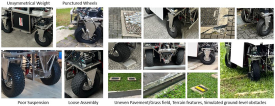
Figure 8.
Robot modification and terrain exposure for threshold classes training data acquisition.
The robot was modified on a minor level for the Moderately safe System-generated class (MS). This includes loosening the components assembly mounting brackets, setting the air pressure of one or more wheels as low, reducing the suspension system performance, and placing offset the heavier items such as the battery. Then, the robot was driven on the same plain terrains as the safe class and a minor level of vibration was noticed compared to the safe class, which is purely due to the degraded system causes. The data were collected and labelled as the MS class. Further, for the Unsafe System-generated class (US), the modifications above intensified more with close observations and safety measures, such as an emergency stop, resulting in a higher vibration of the robot compared to the MS class. The data collected during these trials were labelled as the US class.
The left and right wheels of the robot are kept 0.7 m apart; hence the spot ground-level obstacles are exposed to the particular wheel only, and the deterioration rate is affected by the specific wheel and related assembly only. In this view, if the robot is exposed to the spot obstacles at left-side wheels (front and rear), it will be labelled as MTL or UTL depending on the size of the ground-level obstacles, and, similarly for right-side wheels, MTR or UTR. The advantage of this approach is that the operator can easily avoid the terrain-induced vibration, detecting left or right spot obstacles by moving left and right, utilising the holonomic mobility of the robot as well. Alternatively, if the obstacle is spread like a long root or a large uneven pebbled area, both left/right wheels undergo the same experience; hence, such data are labelled as MT or UT.
Next, for collecting moderately safe terrain-induced classes data, the robot is exposed to typical pavements and grass fields with uneven/unstructured surfaces, damaged/missing tiles pavement, stones, roots, pits, utility hole raised lids, and gutters, including simulated obstacles. Here such selected imperfections had a moderate size of around 2–4 cm, both positive and negative. As explained above, these Moderate Terrain-induced data are recorded as MTL, MTR, and MT. The same exercise and approach are repeated for Unsafe Terrain-induced classes (UTL, UTR, and UT), driving through the undesired terrain features of sizes of around 4-6 cm height, and the data were labelled accordingly.
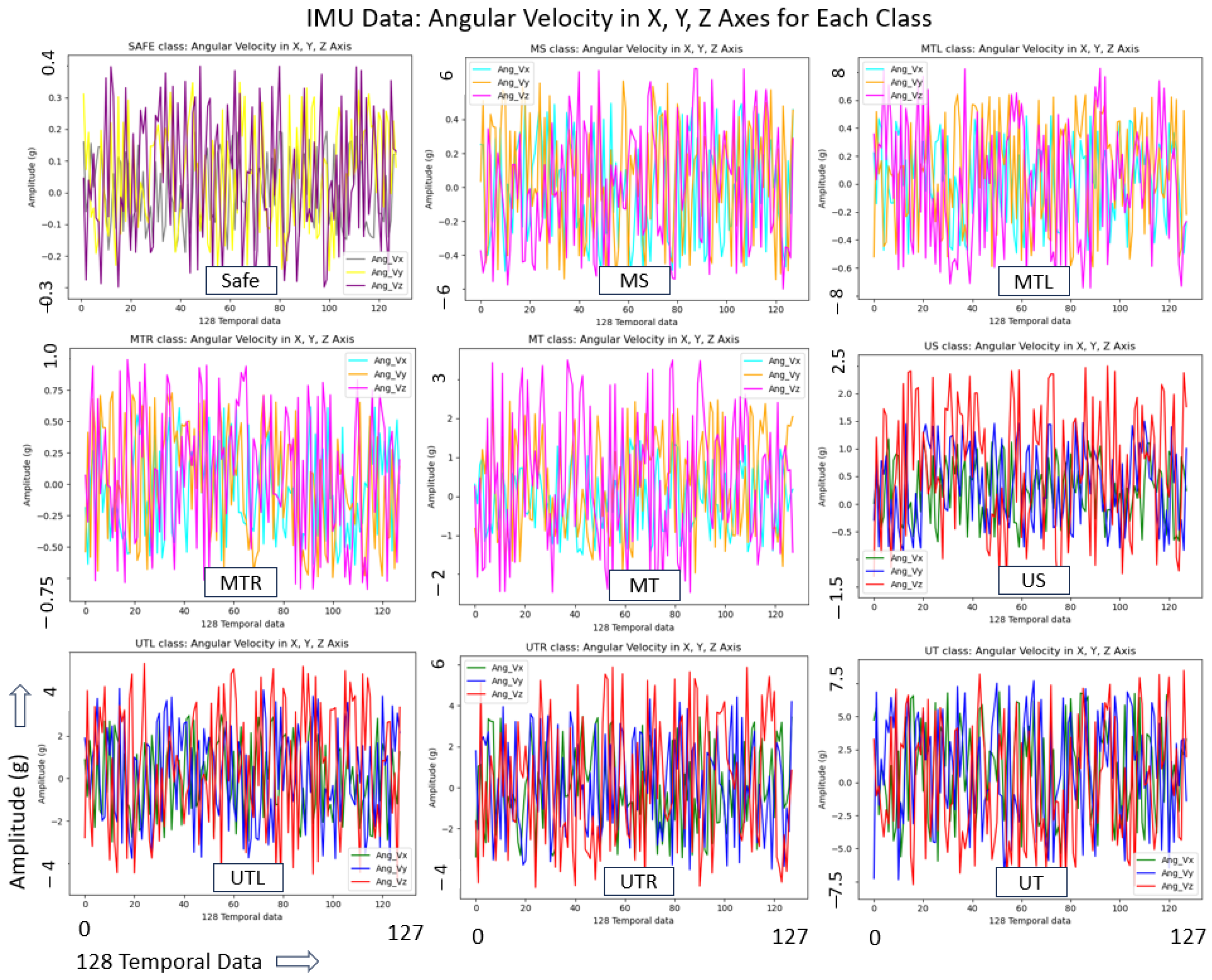
For all Unsafe classes (US, UTL, UTR, and UT), as the robot vibrates more severely, the deterioration rate become faster, and chances of total failure and hazards are high. Hence, during such trials, the robot stopped intermittently and adjusted to continue trials as an unsafe class. Also, all safety measures like close observation and an emergency stop button were taken if needed. For each threshold class, a total of 2500 samples, forming an array of [2500 × 128 × 11], were saved and split into 80% and 20% for training and validation, respectively, for training the 1D CNN model. Additionally, a total of 500 dataset samples were recorded for each class to evaluate the accuracy of the trained model. The vibration-indicated IMU and current sensors data across the nine classes found different values/patterns, enabling a faster convergence in extracting the unique characteristics of each class and a higher prediction accuracy. For a visual representation of this unique dataset for each class, we randomly collected a single dataset of 128 elements and used only five features here for plotting, i.e., features from IMU (angular velocity in X, Y, and Z axes) and the current sensor (left and right wheel current consumption) as shown in Figure 9 and Figure 10.
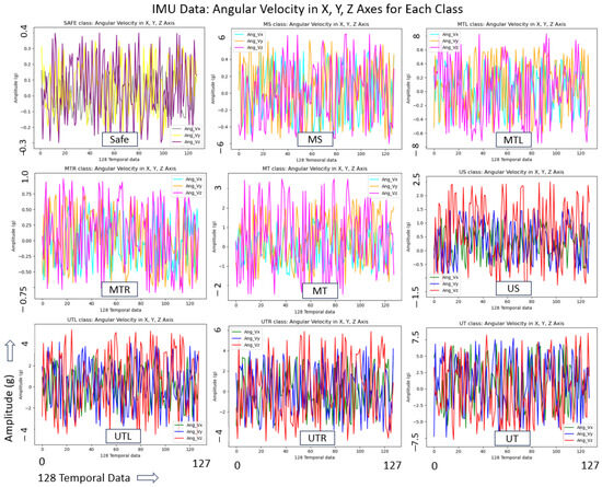
Figure 9.
Vibration-indicated data from IMU sensor for each class.
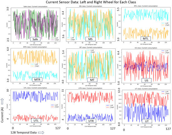
Figure 10.
Vibration-indicated data from current sensors for each class.
As the data features are in different scales, especially the current sensors values, normalisation pre-processing is conducted for the standard scale, supporting faster convergence during the 1D CNN training. Here, IMU data were normalised into −1 to +1 and 0 to 1 for current consumption data following Equations (5) and (6), respectively.
3.2. 1D CNN Model Training and Evaluation Results
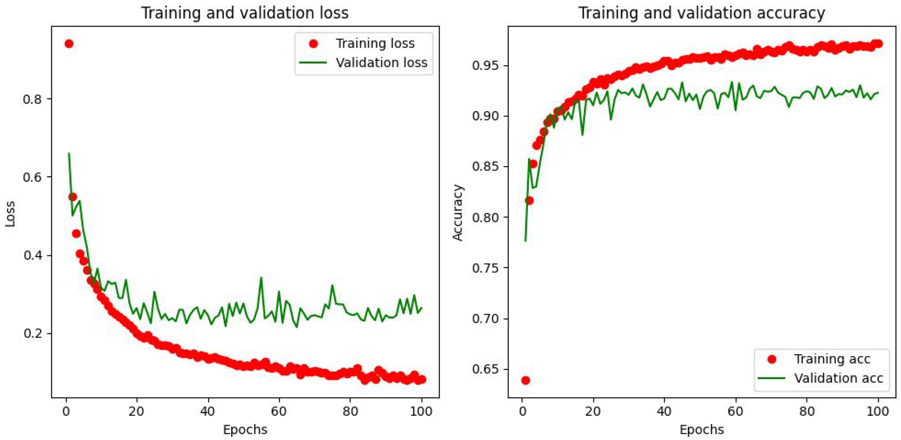
This section provides the 1D CNN model training methodology and the results. The heterogeneous sensors-based unique dataset compiled is trained following a supervised learning strategy using an Nvidia GeForce GTX 1080 Ti-powered workstation and Tensorflow DL-library [43]. To avoid over-learning and for generalisation, a K-fold cross-validation technique is applied, where k = 5, assuring the dataset quality. A momentum with gradient descent optimising strategy is adapted for faster learning and in order not to be stuck with local minima. After tuning with different functions and values, the following hyperparameters are used for the optimum performance of the model. An adaptive learning rate approach optimisation algorithm—an adaptive moment optimisation (Adam) optimiser [44] is applied with a learning rate of 0.001. Here, the exponential decay rates of 0.9 and 0.999 are used for the first and second moment, respectively. Considering this model’s multinomial classification and probability prediction, a categorical cross-entropy loss function is used, ensuring minimum loss while compiling the model. The model performed better when set with a batch size of 32 and an epoch size of 100, as plotted in Figure 11, depicting the loss and accuracy curve graphs during training and validation.
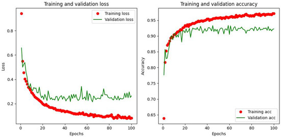
Figure 11.
Loss and accuracy curves during training and validation.
The prediction accuracy of the trained model is assessed based on the statistical metrics precision, recall, F1-score, and accuracy following Equations (7)–(10) [45], where TP, TN, FP, and FN are True Positive, True Negative, False Positive, and False Negative, respectively. The additional 500 samples recorded for each class during data acquisition, which were not part of training, were used for the 1D CNN model evaluation, resulting in an average prediction accuracy of 92.6% with an inference time of 0.238 ms. Table 1 lists the detailed results of this offline evaluation test for each class. Hence, this proposed model is suitable for accurately predicting the vibration threshold classes and condition monitoring applications in outdoor mobile robots

Table 1.
One-dimensional CNN model evaluation result.
A summary of the various challenges and fixes during the 1D-CNN-based classifier training and an evaluation are as follows. The training data acquisition and compilation representing all nine classes were challenging; the data subscription rate for both types of sensors selected (IMU and current sensors) should be the same, and a higher data subscription rate is preferred for a maximum number of predictions per unit of time, where each data feature (a total of 11 features from two types of sensors) with a process window size (128 temporal data) is to be confirmed, forming a single dataset for training. This was realised by developing a data subscription and compiling algorithm, lowering the delay in the Arduino program during the current consumption data subscription for the maximum data subscription rate, and ensuring that the dataset was prepared for all the features with a uniform processing window size. As the proposed IMU and current heterogeneous sensor data fall on different scales, there are difficulties in converging speed during training; hence, the data are brought to a common scale by normalisation. A fast and low computation cost and higher prediction accuracy are crucial for the CM in a mobile robot; hence, the model is structured with a minimum number (four) of convolution layers and tested with different filter sizes and convolution windows in order to choose ideal parameters to fit the given dataset. We opted for a suitable activation function (ReLU) for this classification model, tested with different configurations of pooling and dropout layers to reduce the computation time and overfitting, and finalised the structure of the 1D CNN model for a fast and accurate prediction model. Similarly, the challenges faced during the training for fast convergence and better accuracy were fixed by exploring the various hyperparameters of the model. We used the accuracy and loss curve tool to monitor how well the proposed 1D CNN model fits training data (training loss) and new data (validation loss) and updated the hyperparameters accordingly to finalise a fast and accurate model.
4. Real-Time Experiments and Framework Validation
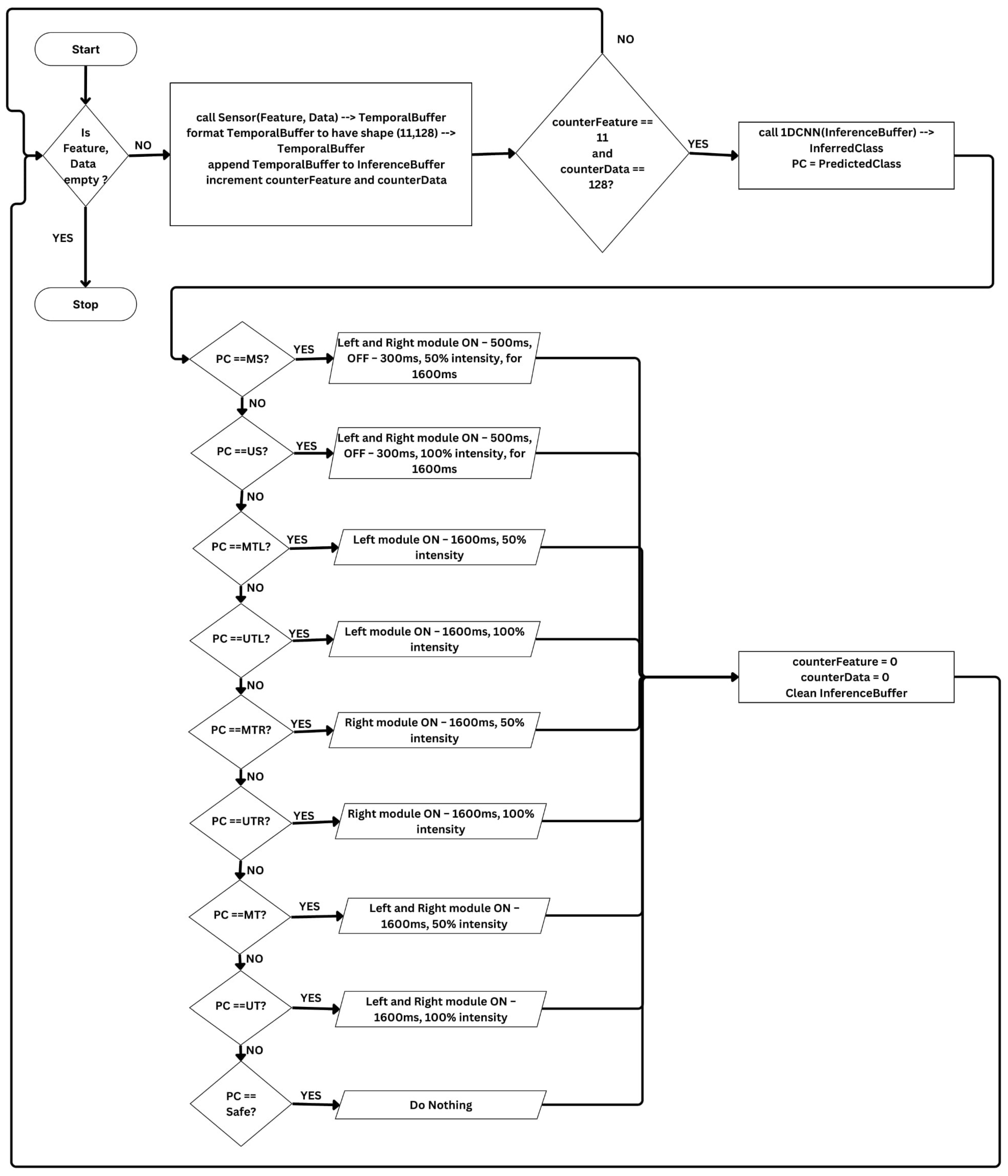
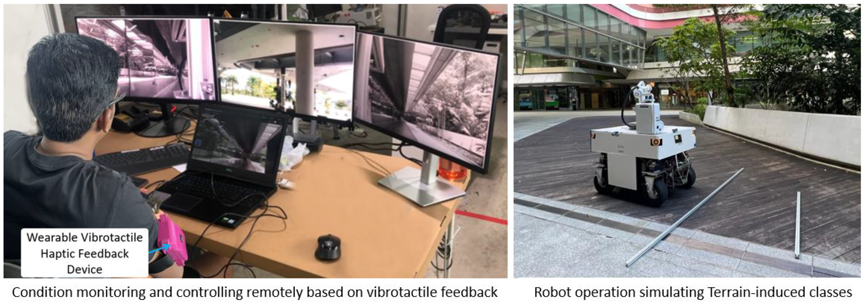
The proposed haptic-feedback-based real-time condition monitoring and remote controlling framework to assess system-generated issues mainly deterioration and minimise traverse through terrain-related flaws reducing the chances of accelerated deterioration and hazards, is validated by conducting three field case studies. Prior to the case studies, a threshold class inference and haptic feedback trigger engine is developed as illustrated in the flowchart, Figure 12. Here, the engine applies the 1D CNN model’s knowledge for every new data sample for inferencing in real-time. A total of 128 temporal data (Data) and 11 features (Feature) form a new dataset [128 × 11] for prediction. A placeholder TemporalBuffer is used during dataset collection, and InferenceBuffer holds one complete dataset as input to the 1D CNN model, runs on the TensorFlow platform, and returns the predicted threshold class. The algorithm also switches the predicted class (PC) to the corresponding vibration pattern, as illustrated. Next, the robot’s shared autonomy and control operations over cloud computing, including the class inference and haptic feedback engine performance, are verified by running the robot on a plain pavement and intruding rods of different sizes, testing safe, MTL, MTR, MT, UTL, UTR, and UT classes as shown in Figure 13.
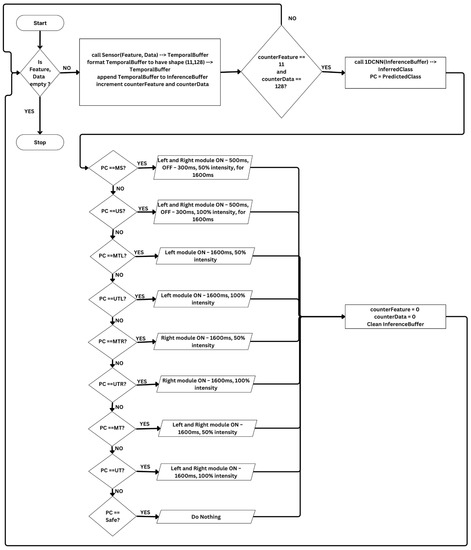
Figure 12.
Flowchart: class inference and haptic feedback engine.
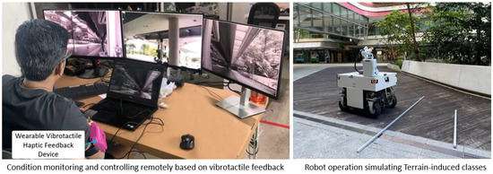
Figure 13.
Pre-trial set up and framework testing.
Field case studies are planned to assess all the threshold classes’ real-time prediction accuracy and how the vibrotactile haptic feedback system enables operators to stop, avoid/minimise ground-level obstacles, and ensure a safe class. Two engineers are trained to learn vibration patterns for each threshold class and are assigned these field trials to monitor and switch over to manual control and operate based on haptic feedback threshold class patterns. The robot is driven in a zig-zag pattern to cover the given test area at a linear speed of 0.3 m/s. The IMU and current sensors data subscription ensure the same at 80 Hz. Before starting each trial, it is also ensured that the robot’s health conditions are good.
A plain ground with uniformly paved tiles is identified for the first case study and a total area of 10 × 12 m2 is selected for testing. There are few drainage utility holes with raised covers as ground-level obstacles and also some aluminium profiles of different sizes are kept, randomly inducing terrain threshold classes. Secondly, an uneven grass field of a test area of 15 × 20 m2 is selected, where many natural surface level flaws of different sizes are observed, such as small pits, stones, and tree roots spread over the ground, that are either passable or blocking. Most of these imperfections are covered by grass so that they can be detected and controlled only through this proposed retrospective technique. Finally, a pavement area is identified with ground-level obstacles, such as missing or broken tiles, small pits, cliffs, kerbs, gutters, and drainage cover at varied heights, and more obstacles are added, which is the same as the first case study, simulating a poorly maintained pavement. Here, a total area of 8 × 16 m2 was selected and isolated from other users, considering further testing as a long-term trial for system-generated classes. The test areas for these three field case studies are shown in Figure 14.
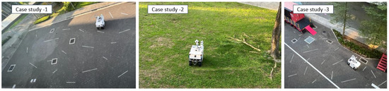
Figure 14.
Three case studies conducted for haptic-feedback-based CM framework validation.
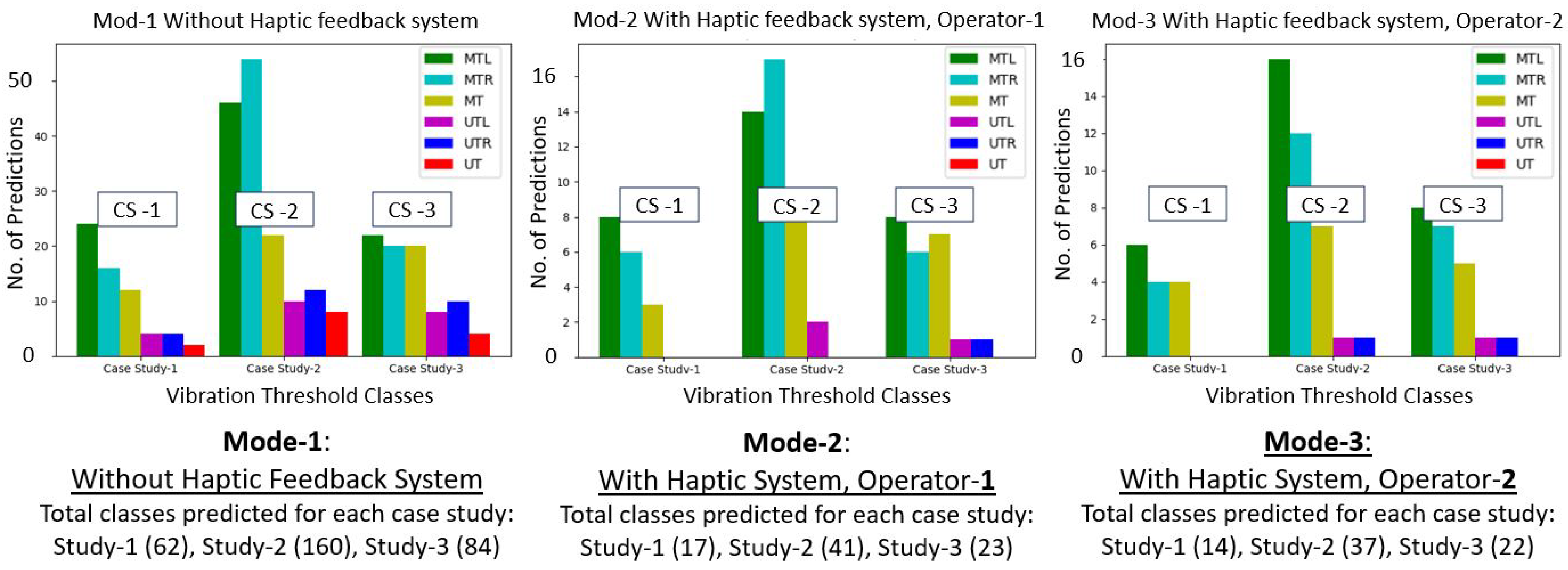
We planned three operation modes for each case study to validate the effectiveness of this proposed haptic-feedback-based condition monitoring and robot controlling framework. The first mode is without executing the proposed haptic feedback system and observing the total number of abnormal threshold classes predicted by the system. This means that the robot is exposed to each test area with uneven terrain, which will cause an accelerated system deterioration or become hazardous if driven continuously. The second and third modes run with the proposed haptic feedback system, and the robot is controlled remotely by operators 1 and 2, respectively. Here, we mainly tested how many ground-level obstacles are avoided based on the haptic feedback when the robot hit the terrain obstacles and control, avoiding the severe features or being limited to the moderate class, or helping not to repeat this for the rear wheels by adequately changing the heading direction. So, here, we mainly checked the total number of abnormal threshold classes reduced compared to without the haptic feedback and controlling system. Also, with two operators, the repetitiveness of the system was tested and validated. The robot drove on the three field areas selected for each mode and covered the whole area once in a zig-zag pattern for each test. The test results summary of these three case studies (CS 1-3) for the three modes of operation is plotted in Figure 15.
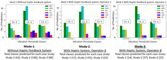
Figure 15.
Threshold class predicted/haptic feedback summary: 3 case studies, 3 operation modes.
Here, for instance, in case study 1, without integrating the haptic feedback system for real-time control, which is mode 1, the robot encountered 62 abnormal terrain features. At the same time, the operator could control the robot for the same test environment, avoiding such terrain anomalies based on the proposed haptic feedback, and encountered only 17 terrain features (as shown in mode 2), reducing the chances of accelerated system degradation and operational hazards.
Accordingly, the total number of abnormal classes exposed without haptic feedback and hence the chances of system deterioration and hazards is four times more than with the proposed system. Also, there is not much difference between modes 2 and 3, i.e., the ease of operation in detecting the feedback pattern and controlling is validated. Additionally, for mode 1 without haptic-feedback-based operations, a safety operator on the spot was involved whenever the robot got stuck, especially when encountering MT, UTL, UTR, and UT classes. The total number of instances of manual involvement needed to resume the operations as per mode 1 for case studies 1–3 was 4, 13, and 5, respectively. This also shows additional time and effort for a robot without integrating such a proposed CM framework, other than the system degradation and chances of hazardous events.
Here, no system-deteriorated classes are observed as the robot was tested in healthy condition and the test was completed in the short term to cover the given area once. So, for testing system-generated classes, the third case study was planned to continue for the long term (average 4 h a day) by removing the comparatively bigger ground-level obstacles, allowing the robot to pass over the obstacles limited to moderated safe terrain-induced classes. The robot was driven in a closed loop and zig-zag pattern in the predefined area. The prediction classes and haptic feedback were tested daily. On the 20th day, an intermittent prediction of the MS class and corresponding haptic feedback pattern was observed. We continued this state for a few hours, closely monitoring the ground truth with safety precautions such as e-stop, and, further, one of the wheels became punctured and generated wobbling. The system occasionally predicted the US class as haptic feedback whenever the wobbling effect was severe. To avoid total failure or hazards, we stopped the operations and triggered maintenance actions to fix the loose assembly and replace the wheel.
We randomly collected 300 samples of each class from the above case studies and long-term tests, closely observing the ground truth and actual haptic feedback to assess the real-time prediction accuracy. Accordingly, the average accuracy was 91.1%, as listed in Table 2 for each class, close to the offline evaluation results. This shows the feasibility and repetitive accuracy of the proposed vibrotactile haptic-feedback-based condition monitoring framework for outdoor mobile robots for real-time applications.
Table 2.
Real-time prediction accuracy of threshold classes.
The proposed study is distinct from the existing techniques, such as shared autonomy, haptic feedback, and terrain classification. The usual shared autonomy works mainly to switch to operator control due to the limitation of safe navigation, i.e., mainly avoiding obstacles in its heading direction. The haptic feedback devices are generally used for human health monitoring and to collect information about the obstacles in mobile robots. The terrain classification intends to detect the type of terrain in order to assess the traversability. However, our proposed work is for CM applications in outdoor mobile robots detecting both the robot’s degradation level and terrain extremities, causing accelerated deterioration and operational hazards. Hence, this is an additional protection other than shared autonomy capabilities.
5. Conclusions
The deployment of a mobile robot in a public outdoor workspace exposed to extreme terrain features is still challenging due to the lack of a proper robot health monitoring system, real-time control that avoids ground-level obstacles, limitations of technology readiness, and other local regulations. This paper discussed and proposed a feasible and novel approach for the real-time condition monitoring and remote control of an outdoor robot by developing an AI-enabled haptic-feedback-based condition monitoring framework that assesses the robot’s health state and enables remote operators to minimise traversing through undesired terrain flaws. We proposed eight abnormal vibration threshold levels for a typical four-wheeled outdoor robot for condition monitoring, including the system health/deterioration status and the wheel–terrain-related undesired effects due to extreme terrain features. The vibration-indicated data for the threshold classes were modelled based on the onboard IMU and current sensors data, which are independent of environment conditions and complement each other, representing the robot’s behaviour for each class. A simple structured 1D CNN model was developed and trained on this heterogeneous sensor data for fast, accurate, and real-time execution. A wearable vibrotactile haptic feedback device architecture suitable for the condition monitoring of outdoor robots and configured multi-level vibrotactile patterns unique to each threshold class is presented, enabling the real-time controlling of the robot. A shared autonomy integrated in-house-developed outdoor fumigation robot was used as a test platform in this work to validate the proposed framework by conducting three field case studies, including a long-term test. Accordingly, the threshold class prediction accuracy was found to be 91.1%, and the effectiveness of the real-time haptic device operation was evaluated to be four times better than the usual practice by assisting either in stopping or minimising the exposure to extreme terrain features. Hence, the proposed AI-enabled vibrotactile feedback-based condition monitoring and remote control significantly impact the robot’s health and operational safety. We will further improve the prediction accuracy by exploring additional sensors as future work suitable for outdoor mobile robots.
Author Contributions
Conceptualisation, S.P., P.V. and M.R.E.; methodology, S.P., R.E.A. and P.V.; software, R.E.A. and S.P.; validation, S.P. and R.E.A.; formal analysis, S.P., M.R.E. and R.E.A.; investigation, S.P. and R.E.A.; resources, M.R.E.; data, S.P. and R.E.A.; writing—original draft preparation, S.P., R.E.A. and P.V.; supervision, M.R.E.; project administration, M.R.E.; funding acquisition, M.R.E. All authors have read and agreed to the published version of the manuscript.
Funding
This research is supported by the National Robotics Programme under its National Robotics Programme (NRP) BAU, Ermine III: Deployable Reconfigurable Robots, Award No. M22NBK0054 and also supported by A*STAR under its “RIE2025 IAF-PP Advanced ROS2-native Platform Technologies for Cross-sectorial Robotics Adoption (M21K1a0104)” programme.
Data Availability Statement
Data will be made available on request.
Acknowledgments
The authors would like to thank the National Robotics Programme, the Agency for Science, Technology and Research, and SUTD for their support.
Conflicts of Interest
The authors declare no conflict of interest.
References
- ABI Research. Labor Shortages and Workplace Safety Concerns Propel Shipments of Outdoor Mobile Robots to 350,000 by 2030. Available online: https://www.abiresearch.com/press/labor-shortages-and-workplace-safety-concerns-propel-shipments-of-outdoor-mobile-robots-to-350000-by-2030/ (accessed on 10 January 2023).
- Zhang, F.S.; Ge, D.Y.; Song, J.; Xiang, W.J. Outdoor scene understanding of mobile robot via multi-sensor information fusion. J. Ind. Inf. Integr. 2022, 30, 100392. [Google Scholar] [CrossRef]
- Liang, Z.; Fang, T.; Dong, Z.; Li, J. An Accurate Visual Navigation Method for Wheeled Robot in Unstructured Outdoor Environment Based on Virtual Navigation Line. In Proceedings of the International Conference on Image, Vision and Intelligent Systems (ICIVIS 2021), Changsha, China, 15–17 June 2021; pp. 635–656. [Google Scholar]
- Dong, Y.; Liu, S.; Zhang, C.; Zhou, Q. Path Planning Research for Outdoor Mobile Robot. In Proceedings of the 2022 12th International Conference on CYBER Technology in Automation, Control, and Intelligent Systems (CYBER), Jilin City, China, 27–31 July 2022; pp. 543–547. [Google Scholar]
- Yang, L.; Wang, L. A semantic SLAM-based dense mapping approach for large-scale dynamic outdoor environment. Measurement 2022, 204, 112001. [Google Scholar] [CrossRef]
- Liu, F.; Li, X.; Yuan, S.; Lan, W. Slip-aware motion estimation for off-road mobile robots via multi-innovation unscented Kalman filter. IEEE Access 2020, 8, 43482–43496. [Google Scholar] [CrossRef]
- Manikandan, N.; Kaliyaperumal, G. Collision avoidance approaches for autonomous mobile robots to tackle the problem of pedestrians roaming on campus road. Pattern Recognit. Lett. 2022, 160, 112–121. [Google Scholar] [CrossRef]
- CETRAN. Centre of Excellence for Testing & Research of Autonomous Vehicles—NTU. Available online: https://cetran.sg/ (accessed on 10 November 2022).
- Reddy, S.; Dragan, A.D.; Levine, S. Shared autonomy via deep reinforcement learning. arXiv 2018, arXiv:1802.01744. [Google Scholar]
- Azcarate, R.F.; Daniela, S.; Hayat, A.; Yi, L.; Muthugala, M.V.J.; Tang, Q.; Povendhan, A.; Leong, K.; Elara, M. Shared Autonomy for Safety Between a Self-reconfigurable Robot and a Teleoperator Using Multi-layer Fuzzy Logic. In Proceedings of the 2022 IEEE/RSJ International Conference on Intelligent Robots and Systems (IROS), Kyoto, Japan, 23–27 October 2022; pp. 141–148. [Google Scholar]
- Lee, S.; Sukhatme, G.S.; Kim, G.J.; Park, C.M. Haptic control of a mobile robot: A user study. In Proceedings of the IEEE/RSJ International Conference on Intelligent Robots and Systems, Lausanne, Switzerland, 30 September–4 October 2002; Volume 3, pp. 2867–2874. [Google Scholar]
- Farkhatdinov, I.; Ryu, J.H.; An, J. A preliminary experimental study on haptic teleoperation of mobile robot with variable force feedback gain. In Proceedings of the 2010 IEEE Haptics Symposium, Waltham, MA, USA, 25–26 March 2010; pp. 251–256. [Google Scholar]
- Rösch, O.J.; Schilling, K.; Roth, H. Haptic interfaces for the remote control of mobile robots. Control. Eng. Pract. 2002, 10, 1309–1313. [Google Scholar] [CrossRef]
- Diolaiti, N.; Melchiorri, C. Obstacle avoidance for teleoperated mobile robots by means of haptic feedback. In Proceedings of the IEEE 1st International Workshop on Advances in Service Robotics, Online, 31 March 2003. [Google Scholar]
- Dupont, E.M.; Moore, C.A.; Collins, E.G.; Coyle, E. Frequency response method for terrain classification in autonomous ground vehicles. Auton. Robot. 2008, 24, 337–347. [Google Scholar] [CrossRef]
- Csík, D.; Odry, Á.; Sárosi, J.; Sarcevic, P. Inertial sensor-based outdoor terrain classification for wheeled mobile robots. In Proceedings of the 2021 IEEE 19th International Symposium on Intelligent Systems and Informatics (SISY), Subotica, Serbia, 16–18 September 2021; pp. 159–164. [Google Scholar]
- Khan, Y.N.; Komma, P.; Bohlmann, K.; Zell, A. Grid-based visual terrain classification for outdoor robots using local features. In Proceedings of the 2011 IEEE Symposium on Computational Intelligence in Vehicles and Transportation Systems (CIVTS) Proceedings, Paris, France, 11–15 April 2011; pp. 16–22. [Google Scholar]
- Weiss, C.; Tamimi, H.; Zell, A. A combination of vision-and vibration-based terrain classification. In Proceedings of the 2008 IEEE/RSJ International Conference on Intelligent Robots and Systems, Nice, France, 22–26 September 2008; pp. 2204–2209. [Google Scholar]
- Suger, B.; Steder, B.; Burgard, W. Traversability analysis for mobile robots in outdoor environments: A semi-supervised learning approach based on 3D-lidar data. In Proceedings of the 2015 IEEE International Conference on Robotics and Automation (ICRA), Seattle, WA, USA, 26–30 May 2015; pp. 3941–3946. [Google Scholar]
- Janssens, O.; Slavkovikj, V.; Vervisch, B.; Stockman, K.; Loccufier, M.; Verstockt, S.; Van de Walle, R.; Van Hoecke, S. Convolutional neural network based fault detection for rotating machinery. J. Sound Vib. 2016, 377, 331–345. [Google Scholar] [CrossRef]
- Kumar, P.; Shankar Hati, A. Convolutional neural network with batch normalisation for fault detection in squirrel cage induction motor. IET Electr. Power Appl. 2021, 15, 39–50. [Google Scholar] [CrossRef]
- Abdeljaber, O.; Sassi, S.; Avci, O.; Kiranyaz, S.; Ibrahim, A.A.; Gabbouj, M. Fault detection and severity identification of ball bearings by online condition monitoring. IEEE Trans. Ind. Electron. 2018, 66, 8136–8147. [Google Scholar] [CrossRef]
- Kiranyaz, S.; Avci, O.; Abdeljaber, O.; Ince, T.; Gabbouj, M.; Inman, D.J. 1D convolutional neural networks and applications: A survey. Mech. Syst. Signal Process. 2021, 151, 107398. [Google Scholar] [CrossRef]
- Eren, L.; Ince, T.; Kiranyaz, S. A generic intelligent bearing fault diagnosis system using compact adaptive 1D CNN classifier. J. Signal Process. Syst. 2019, 91, 179–189. [Google Scholar] [CrossRef]
- Ince, T.; Kiranyaz, S.; Eren, L.; Askar, M.; Gabbouj, M. Real-time motor fault detection by 1-D convolutional neural networks. IEEE Trans. Ind. Electron. 2016, 63, 7067–7075. [Google Scholar] [CrossRef]
- Abdeljaber, O.; Avci, O.; Kiranyaz, S.; Gabbouj, M.; Inman, D.J. Real-time vibration-based structural damage detection using one-dimensional convolutional neural networks. J. Sound Vib. 2017, 388, 154–170. [Google Scholar] [CrossRef]
- Wang, J.; Wang, D.; Wang, X. Fault diagnosis of industrial robots based on multi-sensor information fusion and 1D convolutional neural network. In Proceedings of the 2020 39th Chinese Control Conference (CCC), Shenyang, China, 27–29 July 2020; pp. 3087–3091. [Google Scholar]
- Kim, H.G.; Yoon, H.S.; Yoo, J.H.; Yoon, H.I.; Han, S.S. Development of predictive maintenance technology for wafer transfer robot using clustering algorithm. In Proceedings of the 2019 International Conference on Electronics, Information, and Communication (ICEIC), Auckland, New Zealand, 22–25 January 2019; pp. 1–4. [Google Scholar]
- Onur, K.; Kaymakci, O.T.; Mercimek, M. Advanced Predictive Maintenance with Machine Learning Failure Estimation in Industrial Packaging Robots. In Proceedings of the 2020 International Conference on Development and Application Systems (DAS), Suceava, Romania, 21–23 May 2020; pp. 1–6. [Google Scholar]
- Aliev, K.; Antonelli, D. Proposal of a monitoring system for collaborative robots to predict outages and to assess reliability factors exploiting machine learning. Appl. Sci. 2021, 11, 1621. [Google Scholar] [CrossRef]
- Pookkuttath, S.; Rajesh Elara, M.; Sivanantham, V.; Ramalingam, B. AI-Enabled Predictive Maintenance Framework for Autonomous Mobile Cleaning Robots. Sensors 2022, 22, 13. [Google Scholar] [CrossRef]
- Pookkuttath, S.; Gomez, B.F.; Elara, M.R.; Thejus, P. An optical flow-based method for condition-based maintenance and operational safety in autonomous cleaning robots. Expert Syst. Appl. 2023, 222, 119802. [Google Scholar] [CrossRef]
- Constantin, G.; Maroșan, I.A.; Crenganiș, M.; Botez, C.; Gîrjob, C.E.; Biriș, C.M.; Chicea, A.L.; Bârsan, A. Monitoring the Current Provided by a Hall Sensor Integrated in a Drive Wheel Module of a Mobile Robot. Machines 2023, 11, 385. [Google Scholar] [CrossRef]
- Rapalski, A.; Dudzik, S. Energy Consumption Analysis of the Selected Navigation Algorithms for Wheeled Mobile Robots. Energies 2023, 16, 1532. [Google Scholar] [CrossRef]
- Kryter, R.; Haynes, H. Condition Monitoring of Machinery Using Motor Current Signature Analysis; Technical Report; Oak Ridge National Lab.: Oak Ridge, TN, USA, 1989.
- Sanfilippo, F.; Pettersen, K.Y. A sensor fusion wearable health-monitoring system with haptic feedback. In Proceedings of the 2015 11th International Conference on Innovations in Information Technology (IIT), Dubai, United Arab Emirates, 1–3 November 2015; pp. 262–266. [Google Scholar]
- Devigne, L.; Aggravi, M.; Bivaud, M.; Balix, N.; Teodorescu, C.S.; Carlson, T.; Spreters, T.; Pacchierotti, C.; Babel, M. Power wheelchair navigation assistance using wearable vibrotactile haptics. IEEE Trans. Haptics 2020, 13, 52–58. [Google Scholar] [CrossRef]
- Song, G.; Guo, S.; Wang, Q. A Tele-operation system based on haptic feedback. In Proceedings of the 2006 IEEE International Conference on Information Acquisition, Weihai, China, 20–23 August 2006; pp. 1127–1131. [Google Scholar]
- Dekker, I.; Kellens, K.; Demeester, E. Design and Evaluation of an Intuitive Haptic Teleoperation Control System for 6-DoF Industrial Manipulators. Robotics 2023, 12, 54. [Google Scholar] [CrossRef]
- Pamungkas, D.S.; Ward, K. Tele-operation of a robot arm with electro tactile feedback. In Proceedings of the 2013 IEEE/ASME International Conference on Advanced Intelligent Mechatronics, Wollongong, Australia, 9–12 July 2013; pp. 704–709. [Google Scholar]
- Lee, J.W.; Yu, K.H. Wearable Drone Controller: Machine Learning-Based Hand Gesture Recognition and Vibrotactile Feedback. Sensors 2023, 23, 2666. [Google Scholar] [CrossRef] [PubMed]
- Mitiche, I.; Nesbitt, A.; Conner, S.; Boreham, P.; Morison, G. 1D-CNN based real-time fault detection system for power asset diagnostics. IET Gener. Transm. Distrib. 2020, 14, 5766–5773. [Google Scholar] [CrossRef]
- Abadi, M.; Barham, P.; Chen, J.; Chen, Z.; Davis, A.; Dean, J.; Devin, M.; Ghemawat, S.; Irving, G.; Isard, M.; et al. Tensorflow: A system for large-scale machine learning. In Proceedings of the Osdi, Savannah, GA, USA, 2–4 November 2016; Volume 16, pp. 265–283. [Google Scholar]
- Kingma, D.P.; Ba, J. Adam: A method for stochastic optimization. arXiv 2014, arXiv:1412.6980. [Google Scholar]
- Grandini, M.; Bagli, E.; Visani, G. Metrics for multi-class classification: An overview. arXiv 2020, arXiv:2008.05756. [Google Scholar]


Disclaimer/Publisher’s Note: The statements, opinions and data contained in all publications are solely those of the individual author(s) and contributor(s) and not of MDPI and/or the editor(s). MDPI and/or the editor(s) disclaim responsibility for any injury to people or property resulting from any ideas, methods, instructions or products referred to in the content. |
© 2023 by the authors. Licensee MDPI, Basel, Switzerland. This article is an open access article distributed under the terms and conditions of the Creative Commons Attribution (CC BY) license (https://creativecommons.org/licenses/by/4.0/).