Article

On the Theory of Methane Hydrate Decomposition in a One-Dimensional Model in Porous Sediments: Numerical Study

by
Ahmed K. Abu-Nab
1,2,*,
Alexander V. Koldoba
1,
Elena V. Koldoba
3,
Yury A. Poveshchenko
4,
Viktoriia O. Podryga
4,
Parvin I. Rahimly
4 and
Ahmed E. Bakeer
1,5
1
Phystech School of Applied Mathematics and Informatics, Moscow Institute of Physics and Technology, Dolgoprudny 141700, Russia
2
Department of Mathematics and Computer Science, Faculty of Science, Menoufia University, Shebin El-Koom 32511, Egypt
3
Department of Computational Mechanics, Faculty of Mechanics and Mathematics, Lomonosov Moscow State University, Moscow 119991, Russia
4
Keldysh Institute of Applied Mathematics, Russian Academy of Sciences, Moscow 125047, Russia
5
Department of Mathematics, Faculty of Science, Damanhur University, Damanhur 22516, Egypt
*
Author to whom correspondence should be addressed.
Mathematics 2023, 11(2), 341; https://doi.org/10.3390/math11020341
Submission received: 16 November 2022 / Revised: 2 January 2023 / Accepted: 5 January 2023 / Published: 9 January 2023

Abstract

:
The purpose of this paper is to present a one-dimensional model that simulates the thermo-physical processes for methane hydrate decomposition in porous media. The mathematical model consists of equations for the conservation of energy, gas, and liquid as well as the thermodynamic equilibrium equation for temperature and pressure ( P T ) in the hydrate stability region. The developed model is solved numerically by using the implicit finite difference technique on the grid system, which correctly describes the appearance of phase, latency, and boundary conditions. The Newton–Raphson method was employed to solve a system of nonlinear algebraic equations after defining and preparing the Jacobean matrix. Additionally, the proposed model describes the decomposition of methane hydrate by thermal catalysis of the components that make up the medium through multiple phases in porous media. In addition, the effect of thermodynamic processes during the hydrate decomposition on the pore saturation rate with hydrates a7nd water during different time periods was studied in a one-dimensional model. Finally, in a one-dimensional model over various time intervals, t = 1 , 10 , 50 s , the pressure and temperature distributions during the decomposition of methane hydrates are introduced and investigated. The obtained results include more accurate solutions and are consistent with previous models based on the analysis of simulations and system stability.

1. Introduction

Methane hydrates (MHs) are ice-like crystals composed of natural gas and water molecules under particular thermodynamic circumstances [1,2]. Permafrost regions are known to contain twice as much carbon as all accessible traditional resources combined. They are most commonly found in ocean sediments at sea–continental margins. is the porosity; ( P ) and low temperature ( T ) , this carbon is typically present as CH 4 trapped in the molecular cavities of water as a polyhedral lattice, giving it an ice-like structure. More hydrocarbon reserves are found in the hydrate deposits than in all known conventional fossil fuels, including coal, oil, and natural gas. At ordinary pressure and temperature conditions, one kilogram of hydrate may create 164.6 kg of methane gas and 0.87 kg of water [3]. As a result, natural gas hydrate is seen as a possible future energy resource, prompting several countries to start joint research and development programs in this field. Furthermore, heat and mass transfer through sediment, and thermodynamic parameters influence the formation and decomposition of naturally occurring MHs [4,5]. Thus, sediments and their properties influence heat and mass transfer in naturally occurring MHs.
Indeed, thermodynamic conditions are mainly dependent on hydrate-bearing sediments (HBS), depth, and geothermal gradient, whereas the formation of featured MHs environments in nature is dependent on sediments and their features. Therefore, a thorough study of naturally existing MHs is required to demonstrate varied environments and reservoir conditions [6,7,8,9].
On the other hand, there are currently no commercially viable methods for extracting natural gas from hydrate deposits [10,11,12,13]. The Siberian gas hydrate reservoir is the only experimental instance of long-term gas production from hydrates [14]. When compared to the other recommended ways, this strategy is thought to be the most convenient because it relies on depressurization and encourages the gas hydrate to dissociate by dropping the well bore pressure below the hydrate stability pressure at a specific temperature [15].
To explain and comprehend gas hydrate productivity in the lack of field experience, we depend on laboratory research, short-term production tests from field deposits, and the theoretical formulations of mathematical models [16,17,18,19,20,21]. However, the lack of data on this reservoir makes it difficult to identify the gas production characteristics of natural gas hydrate reservoirs.
More recently, research has focused on the decomposition and production of methane from reservoirs containing methane hydrate, which necessitated the use of non-thermal, multi-stage, and multi-component models.
Since guest gas molecules are trapped in the cavity made by the hydrogen-bonded water molecules in the hydrate, considerable volumes of methane, the primary component of natural gas, are also trapped by MHs [22,23,24]. Gas hydrates, which naturally exist under permafrost, are stable under relatively high pressure and cold temperatures. In this case, the reaction describing the processes of decomposition and formation of MHs can be defined as follows [19,22].
CH 4 N h H 2 O ( s ) CH 4 ( g ) + N h H 2 O ( 1 )
where N h is the hydration number. For the generation of natural gas from hydrate-containing reservoirs, many standard technologies and their combinations have been proposed. Depressurization is the first and most common approach, which involves lowering the reservoir pressure below the hydrate decomposition pressure [23,24], while thermal catalysis is the second technique, which involves heating the reservoir above the temperature at which hydrates decompose [25]. The third method is inhibitor injection, in which methanol or brine is used to transfer the thermodynamic equilibrium and separate the hydrate [26]. Finally, the fourth approach involves dislodging the hydrate with carbon dioxide to produce methane from it. Furthermore, injecting carbon dioxide into reservoirs can reduce emissions while also improving shale oil recovery. Carbon dioxide has many beneficial properties for oil production, such as its high efficiency in developing solubility with oil, which results in oil expansion and reduced viscosity. Therefore, carbon dioxide is very significant for the extraction of oil from unconventional reservoirs [27,28,29]. The endothermic heat generated during the decomposition process of MHs is overcome by the exothermic heat released during the formation of CO2 hydrates. This process also provides the opportunity for carbon sequestration [28].
The current state of knowledge about natural gas hydrate development and decomposition in the marine environment still requires more research since recent efforts to study replacement reactions in porous media with saline water have failed to achieve large recovery rates, owing to mass transfer restrictions. Therefore, for future development of this technology, it is necessary to study the kinetics of the formation and decomposition of MHs and possibly by mixing them with higher order hydrocarbons in unconsolidated porous media and salt water, which simulate true marine sediments. It is also necessary to comprehend the molecular mechanism of the displacement process.
Over the last few decades, there has been a rise in interest in using computational fluid dynamics (CFD) to simulate non-isothermal multiphase multicomponent processes in the subsurface [20]. CFD models, for example, have been used in the petroleum industry since the 1970s to help optimize oil output via steam-overwhelming [27]. Furthermore, since the 1980s, governments and industries have been concerned about an increasing number of environmental engineering issues such as groundwater contamination caused by subsurface petroleum product infiltration, which has led to the development of multiphase multicomponent models to simulate the transport of contaminants in the subsurface [28]. Recent studies have focused on the decomposition and extraction of methane from methane-hydrate-containing reservoirs, which necessitated the use of non-isothermal, multiphase, multicomponent systems. There are many mathematical models and numerical algorithms that have been used to decompose and generate MHs and simulate complex physical and chemical processes [30,31,32]. In addition, researchers also need multi-component, open source, efficient software.
Rempel and Buffett [33] and Xu and Rempel [34] both presented one of these early models in order to determine the rate of hydrate formation when methane is transported to the hydrate stability zone or is created locally by methane sources. These models gave a semi-analytical solution to the mass and energy balance equations, although they did not take into account the source of the methane, the consequent deposition and burial of oceanic sediments [35].
In other previous models, hydrate decomposition has been studied as a moving boundary problem with an isothermal decomposition process [36]. Other researchers regarded hydrate decomposition as a dynamic process and built a three-phase/one-dimensional approach to predict the behavior of gas production from methane hydrate in depressurized conditions [37,38]. These models took into account the flow of gas and water in independent continuity equations as well as time fluctuations in permeability and porosity throughout hydrate decomposition. The numerical results reported closely match the experimental data on gas and water production [35,36,37].
In addition, various mathematical models and simulations for gas production from MHs under depressurized environments have been presented recently by the authors [39,40,41,42]. For instance, there are studies focused on mathematical modeling of the decomposition of gas hydrate deposits via CO2 injection. The approximate analytical solutions for the replacement of CH4 hydrate with CO2 when CO2 is injected into the reservoir and the early phase of hydrate dissociation are effectively described by these mathematical methods [18,21], and some of these calculations were introduced in refs. [43,44,45,46]. The case of CO2 injection in a gaseous state into a natural reservoir containing methane and its gas hydrate was examined by Khasanov et al. [47]. Khasanov et al. [48] used the similar previous technique, which is presented in work [48], but instead of CO2 in the gaseous state, carbon dioxide in the liquid state was provided. However, only the case where methane recovery from the hydrate happens in the replacement mode and is not followed by methane gas hydrate dissociation was studied by Khasanov et al. [48]. In addition, the injection mechanism of a liquid CO2 reservoir into a limited length gas hydrate, accompanied by the dissociation of CH4 gas hydrate and the subsequent generation of CO2 hydrate, was thoroughly investigated.
In the current study, we introduce a numerical simulation of the decomposition of methane hydrate in three phases of flow. Because hydrate decomposition occurs over a long time (thousands to millions of years) in the marine environment, it is allowable to assume local thermodynamic equilibrium and ignore any chemical kinetic effects, which means that the three phases and sediment grains in a small volume are at the same temperature, allowing us to formulate the energy balance of the contents of the porous medium as a whole. To characterize our proposed model, we formulate a system of partial differential equations using the mass balance equations for methane, water, and energy balance. This model also contains the following features: (1) The component splitting between phases is computed using the local thermodynamic equilibrium. (2) Each stage can vanish or reappear in any part of the field. (3) Fluid flow occurs in liquid and gas phases via pressure and temperature, as stated in the polyphasic representation of Darcy’s law, which takes relative permeability into account. (4) Enthalpy, h , is used to demonstrate energy conservation. (5) The latent heat of phase transition is the difference in enthalpy between the hydrate and its reactants is ignored in the proposed model, and heat is transported by conduction and polyphase delay.
Our calculations were applied to a porous medium in a one-dimensional model containing gas, water, and hydrates. The study focuses on three different cases of filtration flow during the decomposition of methane hydrate. The first case considers the flow of two incompressible fluids in which the energy equation breaks down and the temperature distribution does not affect the fluid flow. The second case deals with the problem of displacement of an incompressible liquid at different temperature values. In the third case, we assume that the thermal conditions are constant throughout the computations, such that no hydrates could be formed. This was done in two steps; in the first one, an ideal gas flow was assumed, while the second step implied that the flow was an incompressible liquid with a constant heat capacity.
The paper is organized as follows: The introduction is presented in Section 1. Section 2 presents the description of physical processes. The theoretical analysis and mathematical formulation are investigated in Section 3. The numerical solution methodology is introduced in Section 4. The thermodynamic equilibrium of hydrate decomposition in phases two and three of the porous medium are discussed in Section 5 and Section 6. Finally, the concluding remarks are covered in Section 7.

2. Description of the Physical Approach

MHs are crystalline solid compounds formed by methane gas molecules and water molecules that remain stable at low temperatures and high pressures [1]. These types of conditions can be obtained on maritime continental edges and permafrost zones, where the presence of methane encourages the formation and growth of hydrates. The stability of methane hydrate is controlled by the salinity and the concentration of methane in the water. Our proposed model takes into account that the flow is in three phases (gas, liquid, and hydrate) and that there are two components (methane and water) [15,18,19]. A schematic of the conceptual framework used in this investigation is shown in Figure 1. Assume that the system consists of CH4 and H2O as well as the assumptions of the suggested model and the descriptions of physical processes, which are covered later. Water (H2O) is the only element in the liquid phase and CH4 is the only element in the gas phase. Both the dissolution of CH4 in the liquid phase and the evaporation of H2O into the gas phase are not taken into consideration. According to the thermobaric conditions, a hydrate may form in the system, and the hydrate’s phase contains both parts in the following mass fractions.
CH 4 / H 2 O = ε / 1 ε
Here, ε is the mass fraction of methane in the hydrate’s phase. The pressures in the dynamic three phases were assumed to be the same, which was significant because it ignored the jump in capillary pressure at the gas–liquid interface. The dynamic system for the gas, liquid, and hydrate in this situation is in local thermodynamic equilibrium, keeping the temperatures of all phases constant. In addition, depressurization of a hydrate reservoir is a complex physical–chemical procedure that involves decomposition and reformation, heat transfer, porous media reconstruction, gas migration with water, and other factors. Some basic assumptions are provided to make the mathematical model more accurate and simple relying on some previous theoretical and experimental studies during these hypotheses [3,18,32].
  • The gas hydrates in the numerical simulation are measured in SI units, without taking into account the composition of the salt.
  • The behavior of multiphase fluid flow in uniform porous media is described by Darcy’s law, and hydrate is stagnant in porous media.
  • Gravity and capillary forces are not taken into account.
  • The thermal conductivity that is supposed to be included in the total heat transfer equation as compared to convection is negligible, which means that the thermal conductivities of the energy equations are neglected.
  • The current model discusses the states of filtering flow of a fluid through a porous medium in the case of incompressible fluids by another fluid, by the same fluid, and in the case of an ideal gas.
  • In the case of heat and mass transfer, the influence of diffusion and dispersion was ignored, and during the decomposition process, there is no ice phase.
  • During hydrate decomposition, the hydrate-bearing sediments were considered stiff and not distorted.

3. Theoretical Analysis and Mathematical Model

Hydrate Decomposition in A Three-Phase Porous Medium

In this case, isothermal multiphase flow in porous media presents problems containing phase transitions that are currently being mathematically formulated by systems of nonlinear partial differential equations, and due to the lack of a comprehensive understanding of the qualitative aspects of the thermodynamic effects of systems, several different numerical and theoretical approaches are currently being introduced.
Based on these concerns, Darcy’s law, the laws of conservation of mass and energy, and the equation for thermodynamic equilibrium of gas hydrate stability are introduced by a system that includes basic equations describing the processes of filtration and heat transfer in a porous medium in one-dimensional x coordinates.
Additionally, the capillary pressure jump is neglected, which implies the pressures in the phases are the same. Moreover, the gas phase contains the component CH 4 , while the liquid component is H 2 O . In this paper, the balance equations for energy and mixture components ( CH 4 , H 2 O ) take the following form:
t { m ( E g S g + E w S w + E h S h ) + ( 1 m ) E s } + x { E g W g + E w W w + P W } = 0 ,
t { m ( ρ g S g + ε ρ h S h ) } + x { ρ g W g } = 0 ,
t { m ( ρ w S w + ( 1 ε ) ρ h S h ) } + x { ρ w W w } = 0 .
Here, m is the porosity; t is the time; x represent axis direction distance. S i refers the saturation of three phases; the index i refers to the three phases, for gas, liquid, and hydrate ( i . e . ,   i = g , w , h ) . E g , E w , E h , E s are the density of energy, and ε is the mass fraction of gas in hydrate. ρ i , ρ are defined as the densities for the three phases and the density of sand, respectively. C i , C s are defined as the specific heat for the three phases and skeleton. P is the pressure, and T is the temperature.
The below relationship illustrates the saturation of water, gas, and hydrate:
S g + S w + S h = 1 .
Owing to the laboratory-scale dimensions, in this work, W g , and W w represent the Darcy’s velocities for the water and gas phases, respectively. For fluid flow in porous media, the velocities of gas and water are assumed to follow Darcy’s multiphase law [32,35]:
W g = k χ g ( S g , S h ) μ g P x ,
W w = k χ w ( S w , S h ) μ w P x .
Here, μ g , μ w are the viscosity of gas and water, respectively. k is the intrinsic permeability, and χ g , χ w are the relative permeability of gas and liquid, respectively. In addition, the hydrate filling the pore space interferes with fluid flow, and the absolute permeability change interferes with hydrate saturation. As a result of gas hydrate decomposition, the volume occupied by gas and water increases with time.
Additionally, the thermodynamic equilibrium of gas hydrate stability is strongly dependent on the pressure–temperature relationship, which is defined as follows [19]:
G ( T , P ) = 0 .
Hydrate decomposition is an endothermic reaction, and the rate of decomposition is greatly influenced by temperature [13]. The convective heat transmission, the heat inside and outside in terms of gas and water injection/production, and the heat of hydrate decomposition are included in the balance of energy equation. Moreover, the change in the enthalpy of the gas, water, and hydrate phases is defined as follows [37,38]:
ε h g + ( 1 ε ) h w = h h + H .
Here, H is the latent heat. The specific enthalpies for the three phases are defined as [32,35]:
h i = ε i + P ρ i .

4. Discretization and Linearization of the Governing Equations

Before proceeding to the description of the computational algorithm for the numerical calculations of equations, let us introduce a new notation that makes it possible to describe the finite difference scheme used here more compactly. The total density of energy is defined as follows:
E = m ( S g E g + S w E w + S h E h ) + ( 1 m ) E s .
The mass densities of components ( CH 4 , H 2 O ) :
ρ CH 4 = m ( ρ g S g + ε ρ h S h ) ,
ρ H 2 O = m ( ρ w S w + ( 1 ε ) ρ h S h ) .
The flow for energy and components is defined as:
F E = E g W g + E w W w + P W ,
F CH 4 = ρ g W g ,
F H 2 O = ρ w W w .
Here, W is the total filtration rate as:
W = W g + W w = K Λ P x ,
where Λ = χ g μ g + χ w μ w is the complete movability.
Let us introduce the fraction of the gas phase in the flow (the Buckley function) as the following:
φ = χ g / μ g Λ .
From the Equations (14)–(19), then
F E = K Λ ( φ E g + ( 1 φ ) E w ) P x , F CH 4 = K Λ φ ρ g P x , F H 2 O = K Λ ( 1 φ ) ρ w P x
Furthermore, the flows for energy and components in all cases have the form
F α = K Λ B α P x , α = ( E , CH 4 , H 2 O ) ,
where B α is the corresponding ratio for convenience and K represents the term for intrinsic and relative permeability. By applying the Equations (20) and (21), the system of Equations (3)–(5) takes the following form:
E t + F E x = 0 ,
ρ CH 4 t + F CH 4 x = 0 ,
ρ H 2 O t + F H 2 O x = 0 .
One of the difficulties of the numerical simulation of filtration flows with phase transitions, which includes the problems of formation/ decomposition of gas hydrates, is the change in the number of phases in space and time. This circumstance entails a change in the number of equations that describe the flow. Hence, the four possibilities of greatest interest are as follows:
  • Three-phase flow (gas, liquid, hydrate).
  • Two-phase flow (gas, liquid).
  • Two-phase flow (gas, hydrate).
  • Two-phase flow (liquid, hydrate).
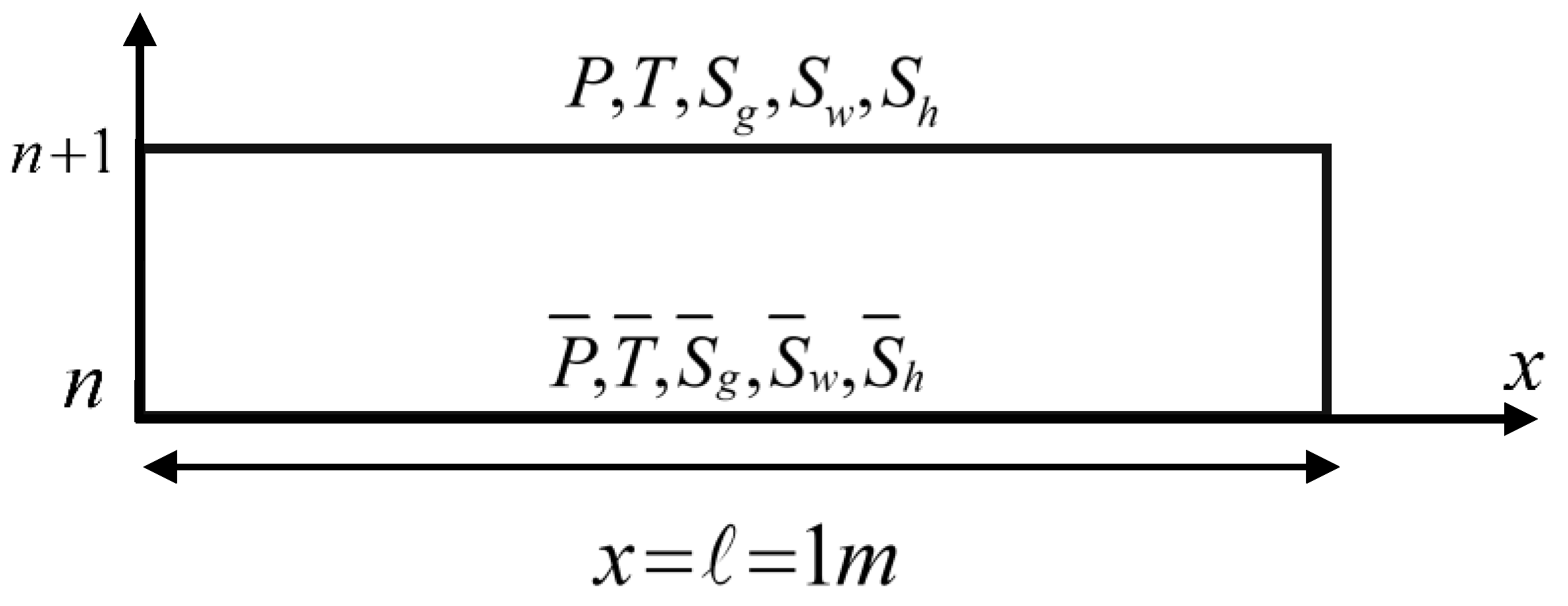
For all cases, the system consists of the balance equations for energy and component masses ( CH 4 , H 2 O ) as well as the condition for normalizing the volume fractions of the phases. The state of the mixture is in a two-phase flow only if G ( T , P ) > 0 , but when G ( T , P ) < 0 , they are not acceptable. It is assumed that the fulfillment of the last inequality, the mixture, passes into a three-phase state, in which the temperature and pressure are related by the conditions of phase equilibrium G ( T , P ) = 0 . In addition, if the mixture forms (locally) three phases of flow, then the algebraic equation is added to the system of equations at the corresponding space–time point G ( T , P ) = 0 . Thus, in case 1 the system of equations contains five equations, while in cases 2–4, the system consists of four equations. The system is closed by defining the dependencies of mass, energy density, the relative viscosity, and permeability coefficients for each phase. The primary variables of our proposed model are pressure P , temperature T , gas saturation S g , water saturation S w , and hydrate saturation S h , as shown in Figure 2 at the time n and n + 1 .
Now, the system of the three Equations (19)–(21) of the balance equations for energy, gas, and liquid, after applying the finite difference technique, can be rewritten in a simplified form as follows:
E i E ¯ i + Δ t Δ x ( F E , i + 1 2 F E , i 1 2 ) = 0 ,
ρ g , i ρ ¯ g , i + Δ t Δ x ( F g , i + 1 2 F g , i 1 2 ) = 0 ,
ρ w , i ρ ¯ w , i + Δ t Δ x ( F w , i + 1 2 F w , i 1 2 ) = 0 ,
The flow components F α = ( F E , F CH 4 , F H 2 O ) are approximated on an implicit time layer as:
F α , i + 1 / 2 = D α , i + 1 / 2 P i + 1 P i 1 Δ x = ( K Λ ) i + 1 / 2 , B α , i + 1 / 2 P i + 1 P i 1 Δ x ,
Here, ( K Λ ) i + 1 / 2 = 2 ( K Λ ) i ( K Λ ) i + 1 ( K Λ ) i + ( K Λ ) i + 1 ; and the coefficient B α is approximated upstream as the following form
B α , i + 1 / 2 = { B α , i P i > P i + 1 B α , i + 1 P i < P i + 1
After applying the finite difference technique to the system of Equations (22)–(24), we obtain the system of nonlinear algebraic equations. Now, the Newton–Raphson algorithm is employed because it is considered one of the most famous methods for finding roots due to its simplicity and speed [32,35].

5. Thermodynamic Equilibrium of Hydrate Decomposition in a Three-Phase Porous Medium

Case 1:
In this case, the porous medium is in a three-phase state, meaning it contains a liquid, a gas, and a hydrate. The heat transfer phenomena during the dissociation of MHs play a significant role. Because hydrates are solids that form gas and water phases upon decomposition, the heat transfer to hydrates is a three-phase flow process (gas, water, and hydrate). Moreover, the energy required for MHs dissociation is 120–140 kJ of energy per mole of methane gas liberated from the hydrate phase and is a solid-to-gas/water phase transition. At a given temperature, T, the different effects of heat and pressure that control MHs decomposition can be calculated from Equation (9). To calculate theoretically the rate of saturation of pores with (gas, water, and hydrate), apply the Newtonian–Raphson method to Equations (22)–(24), then
E i k E ¯ i + ( E P δ P + E T δ T + E S g δ S g + E S w δ S w + E S h δ S h ) i + ( L E δ P ) i + Δ t Δ x ( F E , i + 1 / 2 k F E , i 1 / 2 k ) = 0 ,
ρ i , CH 4 k ρ ¯ i , CH 4 + ( ρ CH 4 P δ P + ρ CH 4 T δ T + ρ CH 4 S g δ S g + ρ CH 4 S w δ S w + ρ CH 4 S h δ S h ) i + ( L CH 4 δ P ) i + Δ t Δ x ( F CH 4 , i + 1 / 2 k F CH 4 , i 1 / 2 k ) = 0 ,
ρ i , H 2 O k ρ ¯ i , H 2 O + ( ρ CH 4 P δ P + ρ H 2 O T δ T + ρ H 2 O S g δ S g + ρ H 2 O S w δ S w + ρ H 2 O S h δ S h ) i + ( L H 2 O δ P ) i + Δ t Δ x ( F H 2 O , i + 1 / 2 k F H 2 O , i 1 / 2 k ) = 0 ,
G ( P , T ) P δ P + G ( P , T ) T δ T = 0 ,
δ S g + δ S w + δ S h = 0 ,
After converting the system of non-linear Equations (30)–(34) into a system of liner algebraic equations for three points, the Gaussian elimination technique is applied to solve the system of linear algebraic equations at each time level, and the iteration process continues until a given level of solution accuracy is achieved. Consequently, the Equations (30)–(34) can be rewritten in the matrix of coefficients, which take the following form:
( a 11 a 12 a 13 a 14 a 15 a 21 a 22 a 23 a 24 a 25 a 31 a 32 a 33 a 34 a 35 0 0 a 43 a 44 a 45 a 51 a 52 0 0 0 ) ( δ P δ T δ S g δ S w δ S h ) + ( L 1 L 2 L 3 0 0 ) δ P = ( Q 1 Q 2 Q 3 Q 4 Q 5 ) ,
where
Q 1 = E ¯ E k Δ t Δ x ( F E , i + 1 / 2 k F E , i 1 / 2 k ) , Q 2 = ρ ¯ CH 4 ρ CH 4 k Δ t Δ x ( F CH 4 , i + 1 / 2 k F CH 4 , i 1 / 2 k ) , Q 3 = ρ ¯ H 2 O ρ H 2 O k Δ t Δ x ( F H 2 O , i + 1 / 2 k F H 2 O , i 1 / 2 k ) , Q 4 = 0 , Q 5 = G ( T k , P k ) .
and
( L α δ P ) i = Δ t Δ x 2 ( D α , i + 1 / 2 ( δ P i + 1 δ P i ) D α , i 1 / 2 ( δ P i δ P i 1 ) ) , α = ( E , CH 4 , H 2 O ) = ( 1 , 2 , 3 ) .
Here, E ¯ , ρ ¯ CH 4 , ρ ¯ H 2 O are the quantities on the explicit time layer, E k , ρ CH 4 k , ρ H 2 O k are the values on k iteration, and δ P = P k + 1 P k , are amendments.
Multiplying the system of equations matrix (35) in the coefficient λ m , we obtain
( m λ m a m 1 + λ 1 L 1 + λ 2 L 2 + λ 3 L 3 ) δ P + m λ m a m 2 δ T + m λ m a m 3 δ S g + m λ m a m 4 δ S w + m λ m a m 5 δ S h = m λ m Q m 1
Multipliers λ m , m = 1 , , 5 are chosen so that the coefficients are turned to zero m λ m a m n = 0 , m = 1 , , 5 , n = 2 , , 5 ; these coefficients are specified in Appendix A.
Then, the result is a three-point equation for δ P i , which is solved by the sweep method [50,51,52]. After obtaining δ P , corrections were calculated at each node of the computational grid δ T , δ S g , δ S l , δ S h from the system.
( a 12 a 13 a 14 a 15 a 22 a 23 a 24 a 25 a 32 a 33 a 34 a 35 0 a 43 a 44 a 45 ) ( δ T δ S g δ S w δ S h ) = ( Q 1 Q 2 Q 3 Q 4 ) Δ t .

6. Thermodynamic Equilibrium of Hydrate Decomposition in a Two-Phase Porous Medium

In cases of two-phase flow (cases = 2, 3, 4), the iterative system algorithm remains the same. The changes in the system equations are illustrated as follows.
The fifth equation, which describes the conditions of phase equilibrium, falls out of the system.
The conditions for normalizing the volume fractions of phases take the following cases:
  • Case 2: S g + S w = 1 ,
  • Case 3: S g + S h = 1 ,
  • Case 4: S w + S h = 1 .
The saturations of moving phases (gas, liquid) are introduced according to the formulas:
s g = S g 1 S h , s w = S w 1 S h .
Case 2:
The Buckley–Leverett problem of displacement of an incompressible fluid by another is discussed in this section. Within the framework of the model described above, it is assumed that the thermobaric conditions in the entire computational domain are constant such that hydrate formation does not occur. In this case, we consider the flow of two incompressible fluids, and the energy equation breaks down in the sense that the temperature distribution does not affect the fluid flow. However, the energy balance equation is solved together with the component mass balance equations.
In the proposed model, the densities and viscosity coefficients of the liquid phases were taken as constant values. The porosity of the skeleton m = 0.35 , permeability k = 0.01 m d , and heat capacity per unit volume c s = 0.873 J kg - 1 K - 1 .
Furthermore, the following dependences of the relative phase permeabilities of liquid phases on saturations are accepted:
χ g ( s g ) = s g 2 , χ w ( s w ) = s w 2 .
In the proposed model, the domain of study is 0 < x < 100 cm , and the initial time is at t = 0 . The computational domain is filled with liquid phase s w | t = 0 = 1 , and pressure and temperature are constant ( P | t = 0 = 24.155 MPa , T | t = 0 = 292 K ) .
At t > 0 , the pressure at the left boundary increases and the gas phase is injected through the left boundary into the domain s g | x = 0 = 1 . In this problem, the overall filtration rate is constant over space W = 1 .
The saturation discontinuity velocity and the discontinuity amplitude are determined by the Jouguet condition:
φ ( s * ) = φ ( s * ) s * ,
where φ ( s ) is the fraction of gas phase flow (Buckley function), which is defined by the following relation:
φ ( s ) = χ g / μ g χ g / μ g + χ w / μ w ,
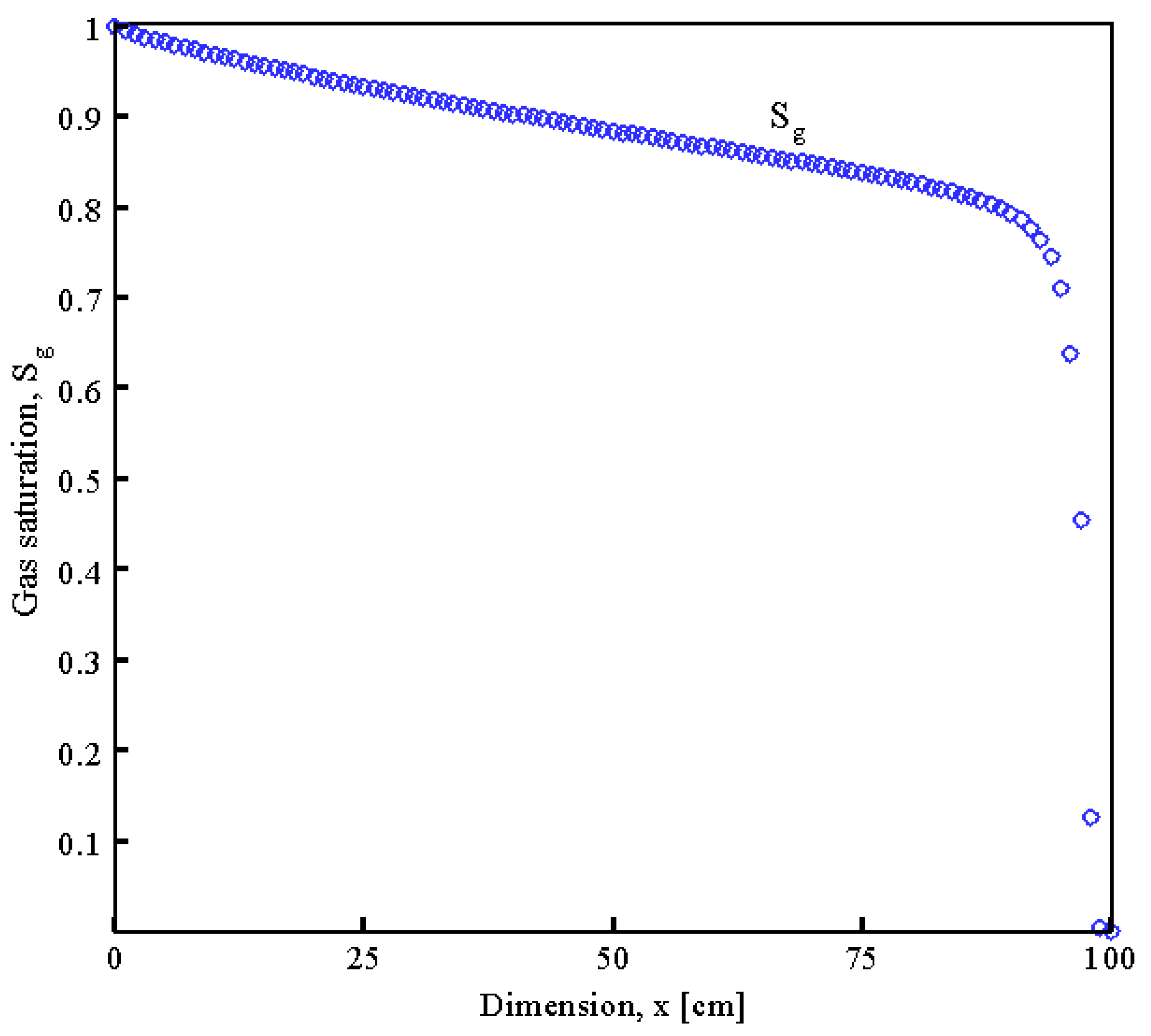
and the velocity of the saturation gap is D = 3.482 cm / s . Regarding the dependence of the relative permeabilities on the saturation adopted here, S * = 0.816 , φ ( S * ) = 1.219 .
The calculations were carried out on a uniform computational grid containing N = 100 intervals, the grid spacing in space is Δ x = 1 cm , and the time integration step Δ t = 1 s .  Figure 3 shows the dependence of the saturation of the gas phase on the coordinate at the time.
Case 3:
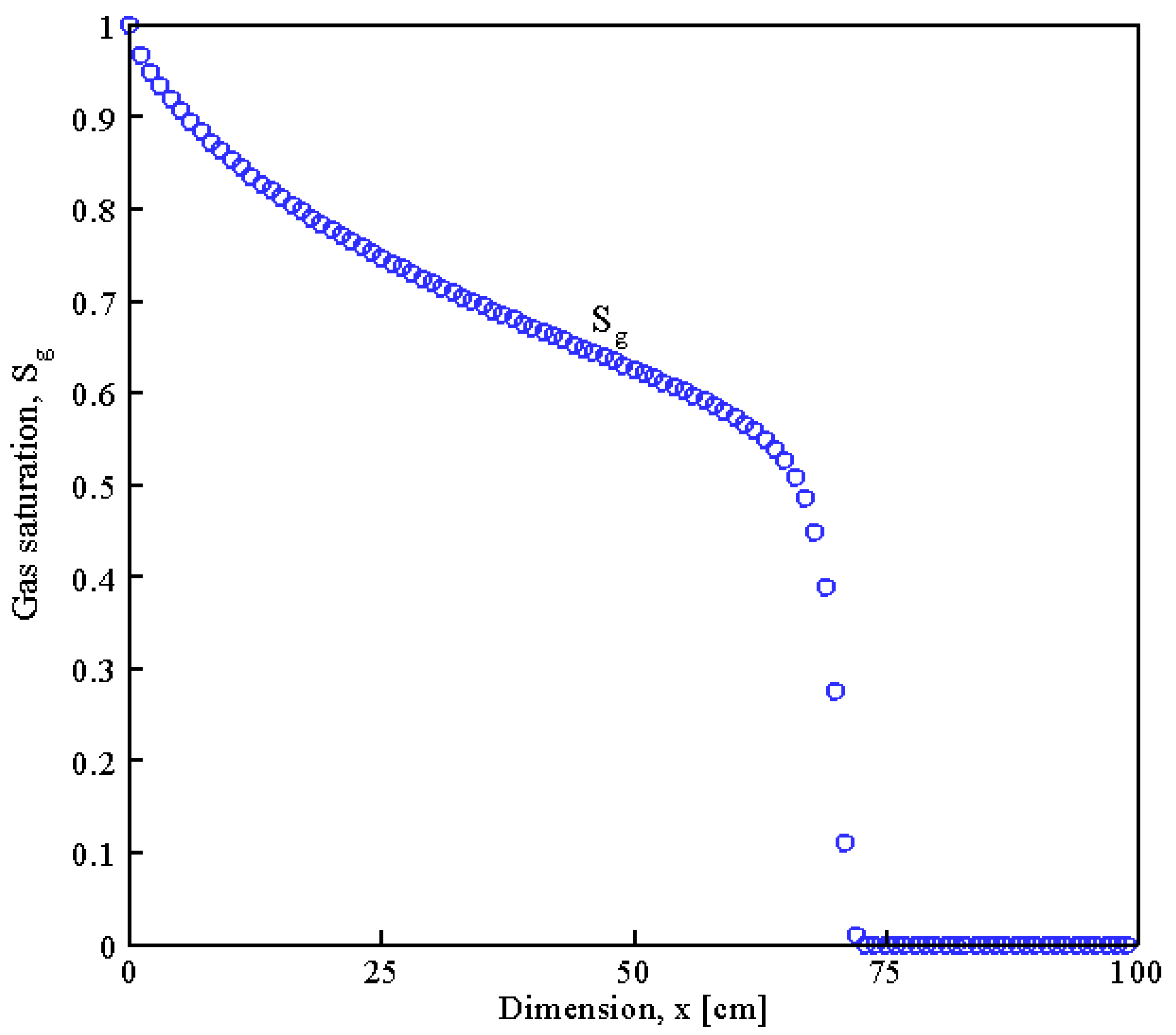
In this section, the problem of displacement of an incompressible fluid by the same fluid at the different temperatures is examined. Within the framework of the proposed model described above, it is assumed that the thermobaric conditions in the entire computational domain are such that no hydrate is formed. The density and viscosity coefficients are constants ρ w = 1000 kg m 3 , μ w = 10 3 Pa s . The heat capacity of a liquid per unit volume is c w = 4165 J kg - 1 K - 1 . In addition, the porosity of the skeleton is m = 0.35 , the permeability is k = 0.01 md , and the heat capacity per unit volume c s = 873 J kg - 1 K - 1 . The problem is considered in the domain 0 < x < 100 cm . At the initial moment of time t = 0 , the computational domain is filled with liquid ( i . e . , s w | t = 0 = 1 ) . The pressure and temperature of which are constant P | t = 0 = 30 MPa , T | t = 0 = 303.15 K . Figure 4 shows that the gas saturation S g during the computational domain x = 100 cm ; at the beginning, it is at its maximum value S g = 1 , and then it begins to decrease gradually, and the reason for this is due to the difference in temperatures during the computational domain.
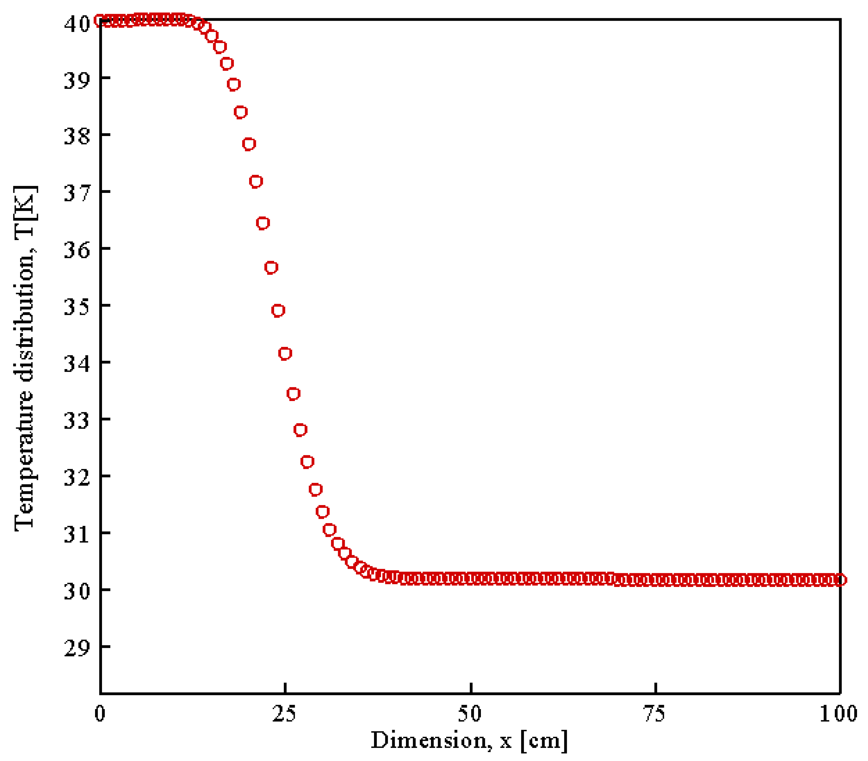
At t > 0 the pressure at the left boundary rises and a fluid with an increased temperature is injected into the domain through it, T | x = l = T l = 313.15 K . In Figure 5, it is noticed that the filtration rate is constant throughout the computational domain, and the temperature distribution decreases as the dimension x increases up to the point x = 38.5 cm . The temperature distribution remains constant from x = 38.5 cm to x = 100 cm , and its rate of propagation is given by the following relation:
D T = W m m c w m c w + ( 1 m ) c s .
Here, D T is the temperature wave velocity. T 0 is the temperature before the rupture, and T l is the temperature after the rupture, and the calculations were carried out on a uniform computational grid containing N = 100 intervals, and the grid step in space is Δ x = 1 cm . Figure 4 and Figure 5 present the results of calculations of the specified problem at the time t = 60 s .
Case 4:
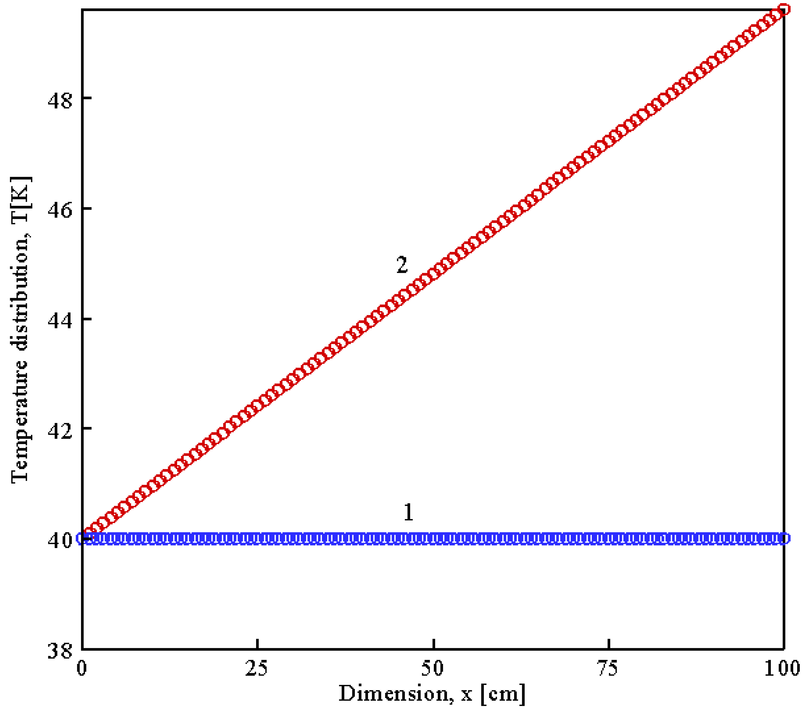
In this case, the problem of stationary filtration flow of fluids through a porous medium is considered in the framework of the model described above, and it is assumed that the thermobaric conditions in the entire computational domain are constant such that no hydrate is formed. In the first step, the flow of an ideal gas is taken into account, and in the second step, the flow is considered to be an incompressible liquid with a constant heat capacity. As is known, in a stationary flow, the specific enthalpy is constant along the streamlines. In a one-dimensional setting, this means that the enthalpy is constant in the computational domain. The specific enthalpy of an ideal gas depends only on temperature; therefore, with a steady flow of an ideal gas, the temperature is constant during the whole computational domain.
For incompressible fluid flows, the filtration rate W is constant, and the specific enthalpy of an incompressible fluid with constant heat capacity is
h w = c w T + P ρ w ,
where c w is the specific heat for water. Under the assumed assumptions about the coefficients, therefore, the temperature profile is a linear function with a slope coefficient
d T d x = 1 ρ w c w d P d x = μ w W ρ w c w K .
At t > 0 the pressure on the left boundary increases and a fluid (gas, liquid) enters the domain through the left boundary at a temperature T | x = 0 = T l = 40 K .
For an ideal gas, ρ g = P R T , E g = P γ 1 , where γ = 4 / 3 is an adiabatic exponent. The energy density of an incompressible fluid is E w = ρ w c w T , and the density and specific heat capacity are ρ w = 1000 kg m - 3 , c w = 4165 J kg 1 K - 1 . The viscosity coefficients of the gas and liquid phases are constant μ g = 0.014 × 10 3 Pa s , μ w = 10 3 Pa s . The heat capacity of the skeleton is equal to 0 ( i . e . , c s = 0 ) for the purity of the computational experiment. The problem is considered in the domain 0 < x < 100 cm . At the initial time t = 0 , the computational domain is filled with the corresponding phase; the pressure and temperature are constant P | t = 0 = 30 MPa , T | t = 0 = 40 K .
At t > 0 , the pressure at the left boundary rises and a fluid (gas or liquid) with an increased temperature is injected into the domain through it, T | x = 0 = T l = 40 K .
The calculations were carried out on a uniform computational grid containing N = 100 intervals, and the grid step in space is Δ x = 1 cm . The calculations were carried out until reaching the steady state. The calculation results are presented in Figure 6.
To illustrate the calculation of filtration flows with a change in number of phases, the following problem is considered. At the initial moment of time, t = 0 s in a one-dimensional model 0 < x < 100 cm filled with hydrate and gas S h | t = 0 = 0.6 , S g | t = 0 = 0.4 at pressure P | t = 0 = 24 MPa and temperature T | t = 0 = 293 K . At t > 0 , the left boundary of the computational domain and the pressure decreases to P | x = 0 = 24 MPa , which leads to the decomposition of the hydrate into gas and liquid and the emergence of a three-phase flow in the vicinity of the left boundary.
Now, we assume that the gas is ideal with a molecular weight M = 16 kg / k mol (methane) and constant isobaric heat capacity c g = γ R γ 1 , γ = 4 / 3 . The fluid is incompressible, v w = constant with constant specific heat c w . The hydrate is considered incompressible, v h = constant with constant heat capacity c h . Additionally, it is assumed that the stresses in the hydrate are reduced to a pressure coinciding with the pressure in the different transition phases.
The condition of phase equilibrium in the three-phase flow is calculated by the equation
η h = ε η CH 4 + ( 1 ε ) η H 2 O ,
Here, η h , η CH 4 , η H 2 O are the chemical potentials for hydrate, methane, and water per unit mass. In addition, the chemical potential of an incompressible fluid with constant heat capacity is
η H 2 O = v w P c w T ln T + c w T + A w T + B w .
Similarly, the chemical potential of the hydrate is defined as follows:
η h = v h P c h T ln T + c h T + A h T + B h ,
and the chemical potential of an ideal gas with constant heat capacity is
η CH 4 = R T ln P c g T ln T + A g T + B g ,
where A h , B h , A w , B w , A g , B g are constants.
The phase equilibrium condition in the three phases (methane, water, and hydrate) system takes the form
ε R ln P + ( c h ε c g ( 1 ε ) c w ) ln T + ( ε v w v h ) P T + A T + B = 0 ,
where A , B are constants connected with A h , B h , A w , B w , A g , B g obvious relations and are chosen from the conditions for the implementation of three-phase equilibrium and the heat of the phase transition at some reference point on ( P , T ) planes, A = 3.1152 × 10 5 J / kg , B = 3.083 × 10 3 J / ( kg K ) . Figure 6 shows the results of calculations of the specified problem at the time, and Table 1 shows the values of the physical parameters used in our proposed model.
Now, the results of testing the developed computational algorithm are examined. Moreover, the hypothesized model in which the filtration flow was initiated by the mass and energy sink in the central part of the computational domain. In addition, the sink terms were added to the balance equations for the energy and mass of the components, which are illustrated below. In the current work, these terms were approximated on an implicit time layer.
The filtration model is considered in one dimension. At the initial moment of time, the pressure, temperature, and volume fractions of the phases are uniformly distributed over the domain as follows:
T | t = 0 = 293 K , P | t = 0 = 2 MPa .
The volume fractions of the phases are homogeneous in space,
S g | t = 0 = 0.2 , S w | t = 0 = 0.3 , S h | t = 0 = 0.5 .
The boundaries of the computational domain are assumed to be impenetrable (i.e., there is no flow through them,
W g | x = 0 = 0 , W w | x = 0 = 0 , W g | x = l = 0 , W w | x = l = 0 .
The intensity of the effluents of the mass of liquid and gas has the following form:
q g = { Φ 1 ( P P 0 ) , 0 < x < 1 0 , otherwise .
Here, P 0 is the constant pressure. Φ 1 is the constant parameter corresponding to the flow in the bottom hole zone due to the pressure difference between the wellbore and the reservoir. The domain of the sources is 0.4 < x < 0.6 m . The energy source takes the form
q ε = q w ε w + q g ( ε g + P ρ g ) ,
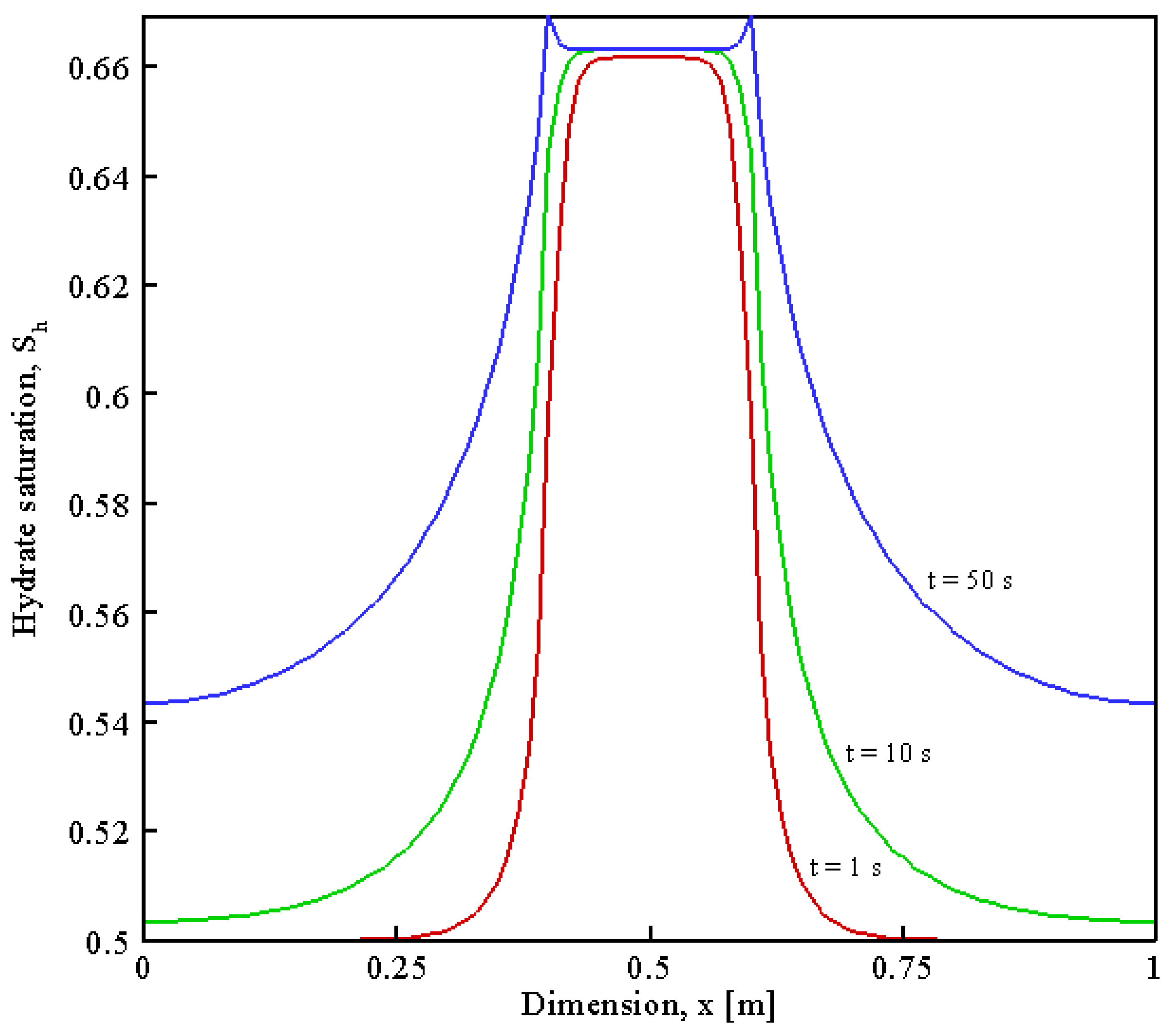
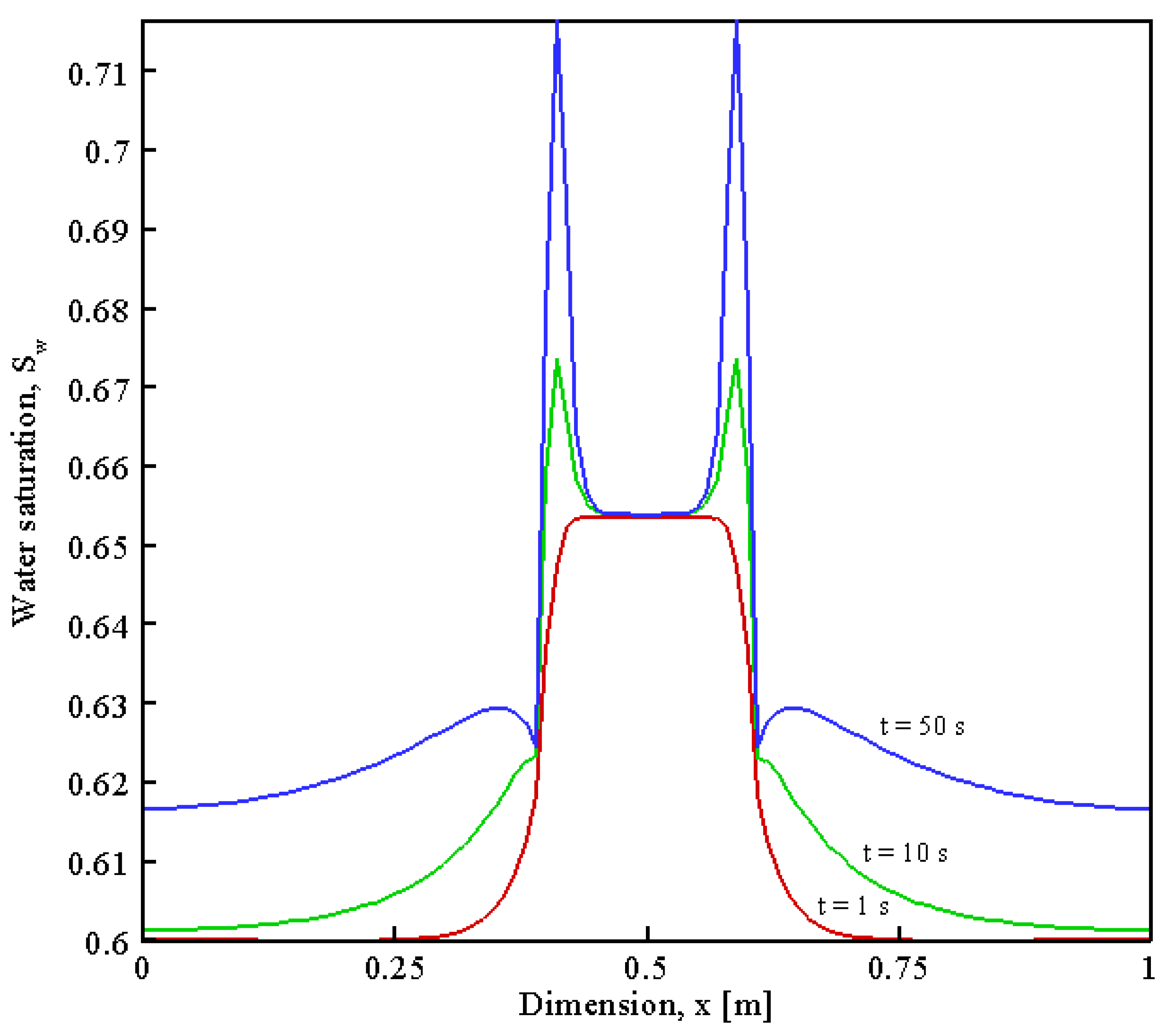
From the previous knowledge and concepts, we are taking into account the adiabatic expansion of the gas, and this type of energy sink makes it possible to consider the work performed by the fluids to push the gas into the well. Figure 7, Figure 8, Figure 9 and Figure 10 show the results of calculations at the different values of time t , t = 1 , 10 , 50 s , and the phase equilibrium conditions are taken in the form
G ( T , P ) = 7.28 ln P ( MPa ) T ( K ) + 169.7 = 0 .
The specific enthalpy of gas, liquid, and hydrate per unit mass in the thermodynamic concepts is as follows:
h h = ε h g + ( 1 ε ) h w H ,
where h g , h w are the specific enthalpies of gas and liquid phases.
The relative permeabilities of these phases were represented as the following:
χ g = ( 1 S h ) 3 k g ( s ) , χ w = ( 1 S h ) 3 k w ( s ) .
where s = S w 1 S h is the saturation of the liquid phase in the thawed part of the pore space.
χ g ( s w ) = { χ g ( S w , min ) , S w < S w , min 1.044 1.7 S w + 0.6 S w 2 , S w , min < S w < S w , max 0 , S w > S w , max ,
χ w ( s w ) = { 0 < S w < S w , min , S w < S w , min 1.477 S w 2 1.587 S w 6 + 1.11 S w 7 0.0473 , S w , min < S w < S w , max χ r l ( S w , max ) , S w > S w , max    
The maximum value of water saturation is S w , max = 0.9 , and the minimum value of water saturation is S w , min = 0.55 .

7. Conclusions

In conclusion, a mathematical model that concentrated on the study of MHs in one dimension was developed, and the implicit finite difference technique was utilized to solve the system of Equations (3)–(6) and (9) given the information above with a moving one-dimensional spatial grid set in the compacting solid sediments and advancing the solution in finite time steps. To allow for short time steps, an implicit approach of the finite difference technique was used for time discretization, and we obtained the following conclusions after analyzing the results:
  • The spatial coordinate is divided into finite intervals.
  • The finite difference method has been carried out by using the computational algorithm code written in the Compaq visual Fortran version 6.6 programming language [53,54].
  • In addition, the initial values and physical parameters used in our numerical calculations of the proposed model are illustrated in Table 1.
  • The Newton–Raphson method was employed to determine the essential variables such as pressure, temperature, and the rate of saturation of pores with hydrate and water in the spatial distribution over different values of time.
  • The solution method demonstrated good numerical stability, sufficient accuracy, and good agreement with the model of Poveshchenko et al. [32] and the model of Rahimly et al. [35].

Author Contributions

A.K.A.-N.: writing—original draft preparation, methodology, writing—review and editing; A.V.K.: software, methodology, supervision, writing—review and editing; E.V.K.: validation, software, methodology; Y.A.P.: conceptualization, formal analysis, software, methodology, supervision; V.O.P.: investigation; P.I.R.: resources; A.E.B.: data curation. All authors have read and agreed to the published version of the manuscript.

Funding

The work of Rahimly P.I. (resources) and Poveshchenko Y.A. (conceptualization, formal analysis, software, methodology, supervision) was supported by the Russian Science Foundation (project № 22-71-10109). The work of Podryga V.O. (investigation) was carried out within the framework of the state assignment of KIAM RAS.

Data Availability Statement

Not applicable.

Conflicts of Interest

The authors declare no conflict of interest.

Appendix A

a 11 = m S g d E g d P a 12 = m ( S g d E g d T + S w d E w d T + S h d E h d T ) + ( 1 m ) d E s d T a 13 = m E g a 14 = m E w a 15 = m E h
a 21 = m ( S g d ρ g d P ) a 22 = m ( S g d ρ g d T ) a 23 = m ρ g a 24 = 0 a 25 = m ε ρ h
a 31 = 0 a 32 = 0 a 33 = 0 a 34 = m ρ w a 35 = m ρ h ( 1 ε )

References

  1. Sloan, E.D. Clathrate Hydrates of Natural Gas, 2nd ed.; Marcel Dekker Inc: New York, NY, USA, 1998. [Google Scholar]
  2. Max, M.D.; Dillon, W.P. Oceanic methane hydrate: Character of the Blake Ridge hydrate stability zone and potential for methane extraction. J. Pet. Geol. 1998, 21, 343–358. [Google Scholar] [CrossRef]
  3. Ruan, X.; Song, Y.; Zhao, J.; Liang, H.; Yang, M.; Li, Y. Numerical simulation of methane production from hydrates induced by different depressurizing approaches. Energies 2012, 5, 438–458. [Google Scholar] [CrossRef] [Green Version]
  4. Malagar, B.R.C.; Lijith, K.P.; Singh, D.N. Singh. Formation & dissociation of methane gas hydrates in sediments: A critical review. J. Nat. Gas Sci. Eng. 2019, 65, 168–184. [Google Scholar]
  5. Gao, Y.; Yang, M.; Zheng, J.N.; Chen, B. Production characteristics of two class water-excess methane hydrate deposits during depressurization. Fuel 2018, 232, 99–107. [Google Scholar] [CrossRef]
  6. Misyura, S.Y. The influence of porosity and structural parameters on different kinds of gas hydrate dissociation. Sci. Rep. 2016, 6, 30324. [Google Scholar] [CrossRef]
  7. Ye, H.; Wu, X.; Li, D. Numerical Simulation of Natural Gas Hydrate Exploitation in Complex Structure Wells: Productivity Improvement Analysis. Mathematics 2021, 9, 2184. [Google Scholar] [CrossRef]
  8. Mao, P.; Wu, N.; Ning, F.; Hu, G.; Sun, J.; Chen, Q.; Guo, Y.; Bu, Q.; Wan, Y. Behaviors of gas and water production from hydrate induced by depressurization with different types of wells. Nat. Gas Ind. 2020, 40, 168–176. [Google Scholar]
  9. Gaidukova, O.; Misyura, S.; Strizhak, P. Key Areas of Gas Hydrates Study: Review. Energies 2022, 15, 1799. [Google Scholar] [CrossRef]
  10. You, K.; Flemings, P.B. Methane Hydrate Formation and Evolution During Sedimentation. J. Geophys. Res. Solid Earth 2021, 126, e2020JB02123. [Google Scholar] [CrossRef]
  11. Kumar, A.; Maini, B.; Bishnoi, P.R.; Clarke, M.; Zatsepina, O.; Srinivasan, S. Experimental determination of permeability in the presence of hydrates and its effect on the dissociation characteristics of gas hydrates in porous media. J. Pet. Sci. Eng. 2010, 70, 114–122. [Google Scholar] [CrossRef]
  12. Xu, Q.; Liu, C.; Liu, Q.; Zhu, Y.; Zhou, H.; Guo, L. Interfacial characteristics of steam jet condensation in subcooled water pipe flow—An experimental and numerical study. Chem. Eng. Sci. 2022, 251, 117457. [Google Scholar] [CrossRef]
  13. Xu, Q.; Zhu, Y.; Zhou, H.; She, Y.; Guo, L. Flow characteristic of steam jet condensed into a water pipe flow—A numerical study. Appl. Therm. Eng. 2022, 205, 118034. [Google Scholar] [CrossRef]
  14. Konno, Y.; Oyama, H.; Nagao, J.; Masuda, Y.; Kurihara, M. Numerical analysis of the dissociation experiment of naturally occurring gas hydrate in sediment cores obtained at the Eastern Nankai Trough, Japan. Energy Fuels 2010, 24, 6353–6358. [Google Scholar] [CrossRef]
  15. Makogon, Y.F. Hydrates of Natural Gas, 1st ed.; Penn Well Publishing Company: Tulsa, OK, USA, 1997. [Google Scholar]
  16. Khataniar, S.; Kamath, V.A.; Omenihu, S.D.; Patil, S.H.; Dandekar, A.Y. Modelling and economic analysis of gas production from hydrates by depressurization method. Can. J. Chem. Eng. 2002, 80, 135–143. [Google Scholar] [CrossRef]
  17. Pooladi-Darvish, M.; Zatsepina, O.; Hong, H.F. Behaviour of Gas Production from Type III Hydrate Reservoirs. In Proceedings of the 6th International Conference on Gas Hydrates, Vancouver, BC, Canada, 6–10 July 2008. [Google Scholar]
  18. Musakaev, N.G.; Khasanov, M.K.; Borodin, S.L. The mathematical model of the gas hydrate deposit development in permafrost. Int. J. Heat Mass Transf. 2018, 118, 455–461. [Google Scholar] [CrossRef]
  19. Gamwo, I.K.; Liu, Y. Mathematical modeling and numerical simulation of methane production in a hydrate reservoir. Ind. Eng. Chem. Res. 2010, 49, 5231–5245. [Google Scholar] [CrossRef]
  20. Zhao, J.; Shi, D.; Zhao, Y. Mathematical model and simulation of Gas Hydrate reservoir decomposition by depressurization. Oil Gas Sci. Technol. Rev. IFP Energ. Nouv. 2012, 67, 379–385. [Google Scholar] [CrossRef] [Green Version]
  21. Khasanov, M.K.; Musakaev, N.G.; Stolpovsky, M.V.; Kildibaeva, S.R. Mathematical model of decomposition of methane hydrate during the injection of liquid Carbon dioxide into a reservoir saturated with methane and its hydrate. Mathematics 2020, 8, 1482. [Google Scholar] [CrossRef]
  22. Song, Y.; Zhang, L.; Lv, Q.; Yang, M.; Ling, Z.; Zhao, J. Assessment of gas production from natural gas hydrate using depressurization, thermal stimulation and combined methods. RSC Adv. 2016, 6, 47357. [Google Scholar] [CrossRef]
  23. Jin, Y.; Yang, D.; Li, S.; Pang, W. Hydrate dissociation conditioned to depressurization below the quadruple point and salinity addition. Fuel 2019, 225, 115758. [Google Scholar] [CrossRef]
  24. Wan, Q.-C.; Si, H.; Li, B.; Li, G. Heat transfer analysis of methane hydrate dissociation by depressurization and thermal stimulation. Int. J. Heat Mass Transf. 2018, 127, 206–217. [Google Scholar] [CrossRef]
  25. Fitzgerald, G.C.; Castaldi, M.J. Thermal stimulation-based methane production from hydrate bearing quartz sediment. Ind. Eng. Chem. Res. 2013, 52, 6571–6581. [Google Scholar] [CrossRef]
  26. Fan, S.; Zhang, Y.; Tian, G.; Liang, D.; Li, D. Natural Gas Hydrate Dissociation by Presence of Ethylene Glycol. Energy Fuels 2006, 20, 324–326. [Google Scholar] [CrossRef]
  27. Yamamoto, K.; Nagakubo, S. Review of Energy Efficiency of the Gas Production Technologies from Gas Hydrate-Bearing Sediments. Front. Energy Res. 2021, 9, 741715. [Google Scholar] [CrossRef]
  28. Goel, N. In situ methane hydrate dissociation with carbon dioxide sequestration: Current knowledge and issues. J. Pet. Sci. Eng. 2006, 51, 169–184. [Google Scholar] [CrossRef]
  29. Bao, J.; Chen, Z.; Xian, C. Investigations of CO2 storage capacity and flow behavior in shale formation. J. Pet. Sci. Eng. 2022, 208, 109659. [Google Scholar]
  30. Omidi, M.; Shahsavand, A.; Share Mohammadi, H. Modeling and simulation of hydrate thermal dissociation around gas production pipe from suboceanic sediment. J. Nat. Gas Sci. Eng. 2016, 32, 48–58. [Google Scholar] [CrossRef]
  31. Kwon, T.-H.; Cho, G.-C. Gas hydrate dissociation in sediments: Pressure-temperature evolution. Geochem. Geophys. Geosystems 2008, 9, Q03019. [Google Scholar] [CrossRef]
  32. Poveshchenko, Y.; Rahimly, P.; Rahimly, O.; Podryga, V.; Gasilova, I. A Numerical Approach to Study the Thermal Influence on Gas Hydrates by Physical Process Splitting. Int. J. Numer. Anal. Mod. 2020, 17, 404–433. [Google Scholar]
  33. Rempel, A.W.; Buffett, B.A. Mathematical models of gas hydrate accumulation, in Gas Hydrates: Relevance to World Margin Stability and Climate Change. Geol. Soc. Spec. 1998, 137, 63–74. [Google Scholar] [CrossRef]
  34. Xu, W.; Ruppel, C. Predicting the occurrence, distribution, and evolution of methane gas hydrate in porous marine sediments. J. Geophys. Res. 1999, 104, 5081–5095. [Google Scholar] [CrossRef]
  35. Rahimly, P.I.; Poveshchenko, Y.A.; Rahimly, O.R.; Podryga, V.O.; Kazakevich, G.I.; Gasilova, I.V. The Use of Splitting with Respect to Physical Processes for Modeling the Dissociation of Gas Hydrates. Math. Model. Comput. Simul. 2018, 10, 69–78. [Google Scholar] [CrossRef]
  36. Chen, X.; Espinoza, D.N.; Luo, J.S.; Tisato, N.; Flemings, P.B. Pore-scale evidence of ion exclusion during methane hydrate growth and evolution of hydrate pore-habit in sandy sediments. Mar. Pet. Geol. 2020, 117, 104340. [Google Scholar] [CrossRef]
  37. Deusner, C.; Bigalke, N.; Kossel, E.; Haeckel, M. Methane production from gas hydrate deposits through injection of supercritical CO2. Energies 2012, 5, 2112–2140. [Google Scholar] [CrossRef]
  38. Ji, C.; Ahmadi, G.; Smith, D.H. Natural gas production from hydrate decomposition by depressurization. Chem. Eng. Sci. 2001, 56, 5801–5814. [Google Scholar] [CrossRef]
  39. Ji, C.; Ahmadi, G.; Smith, D.H. Constant rate natural gas production from a well in a hydrate reservoir. Energy Convers. Manag. 2003, 44, 2403–2423. [Google Scholar] [CrossRef]
  40. Yousif, M.H.; Abass, H.H.; Selim, M.S.; Sloan, E.D. Experimental and theoretical investigation of methane gas hydrate dissociation in porous media. SPE Reserv. Eng. 1991, 6, 69–76. [Google Scholar]
  41. Moridis, G.J. Numerical studies of gas production from class 2 and class 3 hydrate accumulations at the mallik site, Mackenzie Delta, Canada. SPE Res. Eval. Eng. 2004, 7, 175–183. [Google Scholar] [CrossRef]
  42. Corey, A.T. The interrelation between gas and oil relative permeabilities. Prod. Mon. 1954, 19, 38–41. [Google Scholar]
  43. Shagapov, V.S.; Khasanov, M.K. Regimes of methane recovery from gas hydrate on injection of “warm” carbon dioxide into a porous medium. High Temp. 2017, 55, 737–745. [Google Scholar] [CrossRef]
  44. Shagapov, V.S.; Khasanov, M.K.; Musakaev, N.G.; Duong, N.H. Theoretical research of the gas hydrate deposits development using the injection of carbon dioxide. Int. J. Heat Mass Transf. 2017, 107, 347–357. [Google Scholar] [CrossRef]
  45. Shagapov, V.S.; Musakaev, N.G.; Khasanov, M.K. Injection of liquid carbon dioxide into a reservoir partially saturated with methane hydrate. J. Appl. Mech. Tech. Phys. 2016, 57, 1083–1092. [Google Scholar] [CrossRef]
  46. Khasanov, M.K.; Shagapov, V.S. Methane Gas Hydrate Decomposition in a Porous Medium Upon Injection of a Warm Carbon Dioxide Gas. J. Eng. Phys. Thermophys. 2016, 89, 1123–1133. [Google Scholar] [CrossRef]
  47. Khasanov, M.K.; Stolpovsky, M.V.; Gimaltdinov, I.K. Mathematical model for carbon dioxide injection into porous medium saturated with methane and gas hydrate. Int. J. Heat Mass Transf. 2018, 127, 21–28. [Google Scholar] [CrossRef]
  48. Khasanov, M.K.; Stolpovsky, M.V.; Gimaltdinov, I.K. Mathematical model of injection of liquid carbon dioxide in a reservoir saturated with methane and its hydrate. Int. J. Heat Mass Transf. 2019, 132, 529–538. [Google Scholar] [CrossRef]
  49. Zhang, L.; Zhang, C.; Zhang, K.; Zhang, L.; Yao, J.; Sun, H.; Yang, Y. Pore-scale investigation of methane hydrate dissociation using the lattice Boltzmann method. Water Resour. Res. 2019, 55, 8422–8444. [Google Scholar] [CrossRef]
  50. Eduardo Lozano, E.; Aslam, T.D. Implicit fast sweeping method for hyperbolic systems of conservation laws. J. Comput. Phys. 2021, 430, 110039. [Google Scholar] [CrossRef]
  51. Zuev, A.I. On an algorithm for solution of nonlinear systems by the sweep method. Trudy Mat. Inst. Steklov. 1966, 74, 152–155. [Google Scholar]
  52. Bulygin, A.D. Algorithm of the Parallel Sweep Method for Numerical Solution of the Gross–Pitaevskii Equation with Highest Nonlinearities. Supercomput. Front. Innov. 2018, 5, 115–118. [Google Scholar]
  53. Galperin, B. Large Eddy Simulation of Complex Engineering and Geophysical Flows; Cambridge University Press: London, UK, 1993. [Google Scholar]
  54. Chivers, I.D.; Sleightholme, J. Introduction to Programming with Fortran; Springer-Verlag London Limited: London, UK, 2006. [Google Scholar]
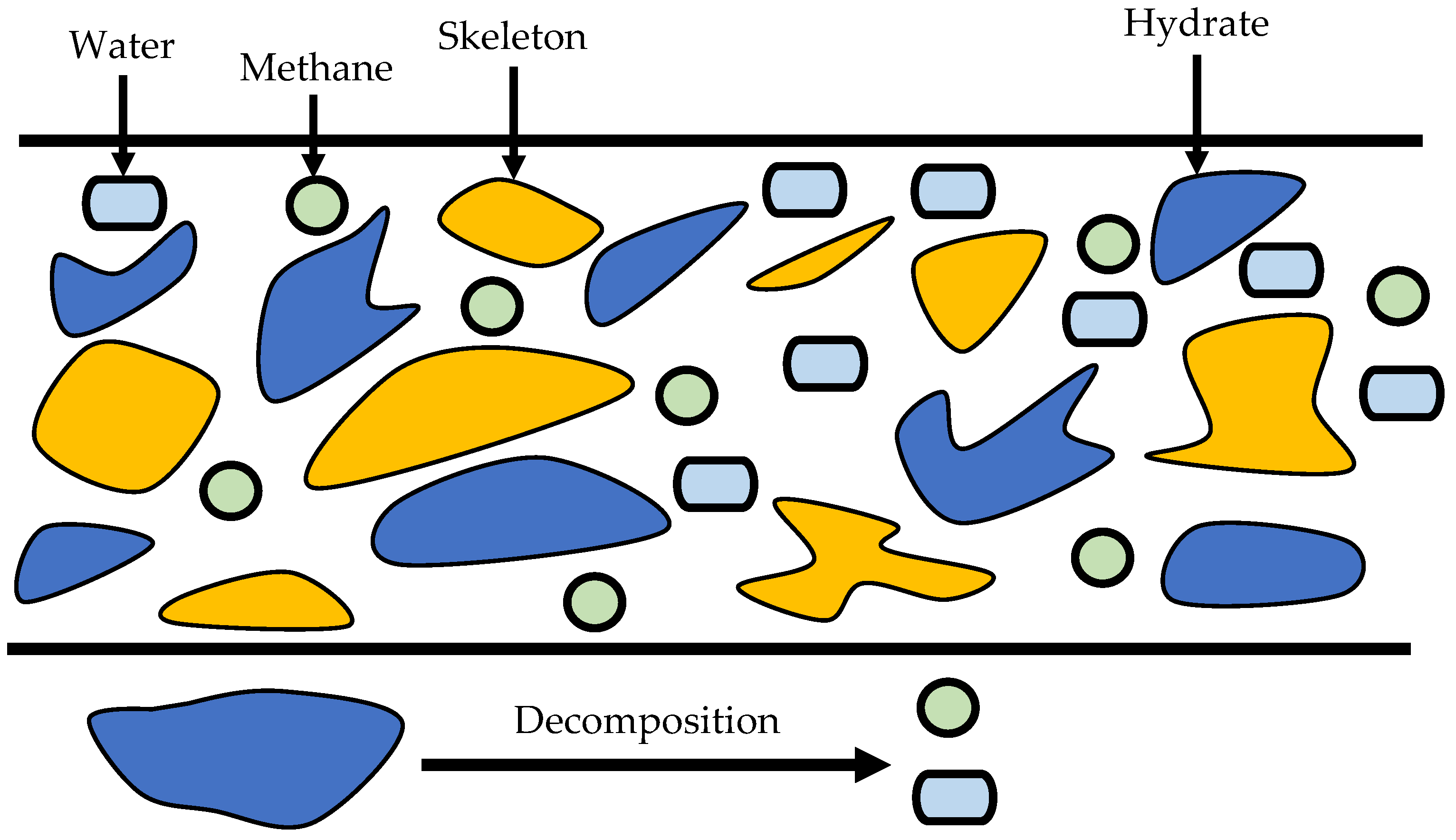
Figure 1. Scheme of the problem of the MHs decomposition in a one-dimensional model in the case of multiphasic flow [49].
Mathematics 11 00341 g001
Figure 2. Schematic diagram of the initial and boundary conditions of the hydrate decomposition in a one-dimensional model.
Mathematics 11 00341 g002
Figure 3. Gas saturation S g versus dimension x at constant thermobaric conditions in the computational domain.
Mathematics 11 00341 g003
Figure 4. Gas saturation S g versus dimension x at the different thermobaric conditions in the computational domain.
Mathematics 11 00341 g004
Figure 5. Temperature distribution T versus dimension x at the different thermobaric conditions in the computational domain.
Mathematics 11 00341 g005
Figure 6. Temperature distribution T versus dimension x ; curve 1 represents the thermal distribution in the case of an ideal gas, and curve 2- represent the different thermobaric conditions in the computational domain.
Mathematics 11 00341 g006
Figure 7. Hydrate saturation distribution S h versus dimension x at the different moments of time t = 1 , 10 , 50 s in the three-phase flow.
Mathematics 11 00341 g007
Figure 8. Water saturation distribution S w versus dimension x at the different moments of time t = 1 , 10 , 50 s in the three-phase flow.
Mathematics 11 00341 g008
Figure 9. Pressure distribution P versus dimension x at the different moments of time t = 1 , 10 , 50 s in the three-phase flow.
Mathematics 11 00341 g008
Figure 10. Temperature distribution T versus dimension x at the different moments of time t = 1 , 10 , 50 s in the three-phase flow.
Mathematics 11 00341 g009
Table 1. The physical parameters and values used in our calculations [32,35].
ParameterValueUnitDescription
P 0 2 MPa Initial pressure
c g 2500 J kg - 1 K - 1 Heat capacity of gas
c w 4165 J kg - 1 K - 1 Heat capacity of liquid
c s 873 J kg - 1 K - 1 Heat capacity of skeleton
m 0.35 - Porosity
S g 0.2 -Initial saturation of the gas
S w 0.3 -Initial saturation of the liquid
S h 0.5 -Initial saturation of the hydrate
ρ w 1000 kg m - 3 Density of liquid
ρ h 910 kg m - 3 Density of hydrate
ρ s 2800 kg m - 3 Density of skeleton
R ( 8.31 × 10 3 ) / 16 J kg - 1 Gas constant
γ 4 / 3 - Adiabatic exponent
μ g 0.014 × 10 3 Pa s Viscosity of the gas
μ l 10 3 Pa s Viscosity of the liquid
ε 0.1 - The mass fraction of methane in the hydrate
H 514,810 J kg - 1 The latent heat of phase transition
Φ 1 10 8 M Pa 1 s 1 m 3 Source of characteristics in the downhole area
N h --The hydration number
Superscripts
0 Initial
i Three phase equilibrium
g Gas
w Liquid
h Hydrate
Abbreviations
MHs Methane hydrates
FDM Finite difference method
HBS Hydrate-bearing sediments
Disclaimer/Publisher’s Note: The statements, opinions and data contained in all publications are solely those of the individual author(s) and contributor(s) and not of MDPI and/or the editor(s). MDPI and/or the editor(s) disclaim responsibility for any injury to people or property resulting from any ideas, methods, instructions or products referred to in the content.