Article

An Isogeometric Over-Deterministic Method (IG-ODM) to Determine Elastic Stress Intensity Factor (SIF) and T-Stress

by
Khadija Yakoubi
1,*,
Ahmed Elkhalfi
1,*,
Hassane Moustabchir
2,
Abdeslam El Akkad
1,3,
Maria Luminita Scutaru
4,* and
Sorin Vlase
4,5
1
Faculty of Science and Technology, Sidi Mohamed Ben Abdellah University, Fez 30000, Morocco
2
Laboratory of Systems Engineering and Applications (LISA), Sidi Mohamed Ben Abdellah University, Fez 30000, Morocco
3
Département de Mathématiques, Centre Regional des Métiers d’Education et de Formation de Fès Meknès (CRMEF Fès-Meknès), Rue de Koweit 49, Ville Nouvelle, Fez 30050, Morocco
4
Department of Mechanical Engineering, Faculty of Mechanical Engineering, Transylvania University of Brasov, B-dul Eroilor 29, 500036 Brasov, Romania
5
Technical Sciences Academy of Romania, B-dul Dacia 26, 030167 Bucharest, Romania
*
Authors to whom correspondence should be addressed.
Mathematics 2023, 11(20), 4293; https://doi.org/10.3390/math11204293
Submission received: 23 July 2023 / Revised: 11 October 2023 / Accepted: 13 October 2023 / Published: 15 October 2023

Abstract

:
In order to examine the significance of Stress Intensity Factor and T-stress (K-T parameters) in modeling pressure-cracked structures, we propose a novel method known as the Isogeometric Over-Deterministic Method IG-ODM. IG-ODM utilizes the computation of stress and displacement fields through Extended Isogeometric Analysis to improve the geometry and enhance the crack. Subsequently, these results are incorporated into the Williams expression, resulting in a set of deterministic equations that can be solved using a common solving method; this particular combination has never been attempted before. IG-ODM enables the computation of stress intensity factor SIF, T-stress, and higher-order parameters in the Williams expansion. To validate the effectiveness of this method, we conducted tests on a single-edge uniaxial-stress-cracked plate and a central uniaxial-stress-cracked plate. The results showed an error ranging from 0.06% to 2%. The obtained results demonstrate accuracy and satisfaction when compared to existing findings.
MSC:
82C27; 65K15

1. Introduction

Asymptotic analysis is an approach which consists of giving an asymptotic development using the defect parameters and the links with the stress/strain field around the crack. According to Cotterell [1], the first term of Williams expansion is the stress intensity factor SIF, determining crack initiation, the next is the T-stress controlling the stability of the crack direction, and the third verifies the stability of the crack propagation.
Several studies have demonstrated that T-stress has a major impact on crack behavior. Nejati et al. [2] investigated the link between T-stress and material properties. Matvienko [3] discussed the influence of T-stress in fracture mechanics. Ayatollahi and Zakiri [4] studied the effect of T-stress on fringe patterns around the crack tip in mode II using the theory of photoelasticity. Jayadevan [4] demonstrated that when the T-stress is negative, the plastic zone appears like butterfly wings. When there is a positive T-stress, these wings will reverse towards the back of the fracture. Ayatollahi and Hashmi [5] demonstrated the remarkable effect of composite patching on T-stress. Sherry et al. [6] described various methods, such as the Eshelby J-integral method, weight function technique, interaction integral method, stress substitution method, and stress difference methods, for determining T-stress. T-stress affects the plastic zone [7] and propagation direction [8]. A negative T-stress stabilizes the fracture path, which means that a minor disruption in the crack path is soon attenuated, whereas a positive T-stress emphasizes deviations, and crack initiation angle [9]. Miao et al. [10] evaluated the role of T-stress on crack initiation and crack bottom plasticity through 3D finite element analysis of three specimens: CCP, CTS, and FPB. Yakoubi et al. [10] studied the utility of the K-T approach in modeling pressure fractured structures.
In the literature, there are several methods to determine the crack parameters, specifically T-stress. These include Stress Different Methods (SDM) introduced by Yang et al. [11], which eliminate errors by considering the variation of numerical values near the crack point. Maleski et al. developed the Extrapolation method, and Wang et al. calculated the stress by the superposition method; in the case of a sample with a fracture loaded with the nominal mode T is a superposition of the T-stress for two situations: the first is a stress T for a cracked specimen loaded with a pressure σ ( x ) on its lips, while the second is a stress T in an uncracked specimen under a nominal load. Hou et al [12] developed the Esheby integral approach for estimating the T-stress, which takes advantage of the path-independent J-integral’s characteristics. The over-deterministic method (ODM) [13] is another approach used to determine crack parameters, including SIF, T-stress, and higher-order parameters in the Williams expansion. ODM has demonstrated efficacy in several studies [14,15].
The SIF and T-stress are crucial in the research of cracking in linear elasticity. Singular stress entities are frequently used to represent the area around the crack tip. SIF is used to assess their resistance. The parameter T is the non-singular stress that characterizes the local stress field near the fracture tip. T-stress has the role of enriching the parameter K (SIF) and the model in the elastic stress zone. The majority of approaches only consider SIF extraction and pay little attention to T-stress and higher-order terms. The transverse constraint, or T-stress, acts parallel to the crack’s propagation.
Isogeometric analysis (IGA) is a computer approach for simulating physical processes in engineering and mathematics. IGA is an approach that integrates finite element analysis (FEA) with classical NURBS-based CAD design tools. It has shown promising results in various fields, including vibration analysis [16,17], composites, and optimization problems [18]. Farshid Fathi et al. [19] presented geometrically nonlinear extended iso-geometric analysis (X-IGA) for cohesive fracture. Wenbin Hou et al. [20] coupled X-IGA and B++ spline to study crack behavior in 2D elasticity solids. X-IGA combines isogeometric analysis with the extended finite element method (X-FEM), utilizing IGA for accurate geometry representation and X-FEM for crack enrichment. The dynamic fracture behavior of stationary fractures in isotropic/orthotropic medium under impact stress was studied by Yadav et al. [21] using the X-IGA approach. Ghorashi et al. [20] demonstrated that X-IGA outperforms X-FEM in terms of accuracy, requiring significantly fewer elements to achieve an error of less than 0.1.
The objective of this study is to compute the K-T parameters in a simple and efficient method; IG-ODM employs Extended Isogeometric Analysis to calculate stress and displacement distributions, thereby refining the geometry and augmenting crack behavior. These outcomes are then integrated into the Williams expression, yielding a series of deterministic equations solvable through a conventional method. This unique combination represents an unprecedented endeavor in this field.
The article is organized as follows: Section 2 discusses X-IGA and iso-geometric over-deterministic method. Section 3 presents the numerical application, result, and discussion. Finally, the conclusion is provided in the subsequent section.

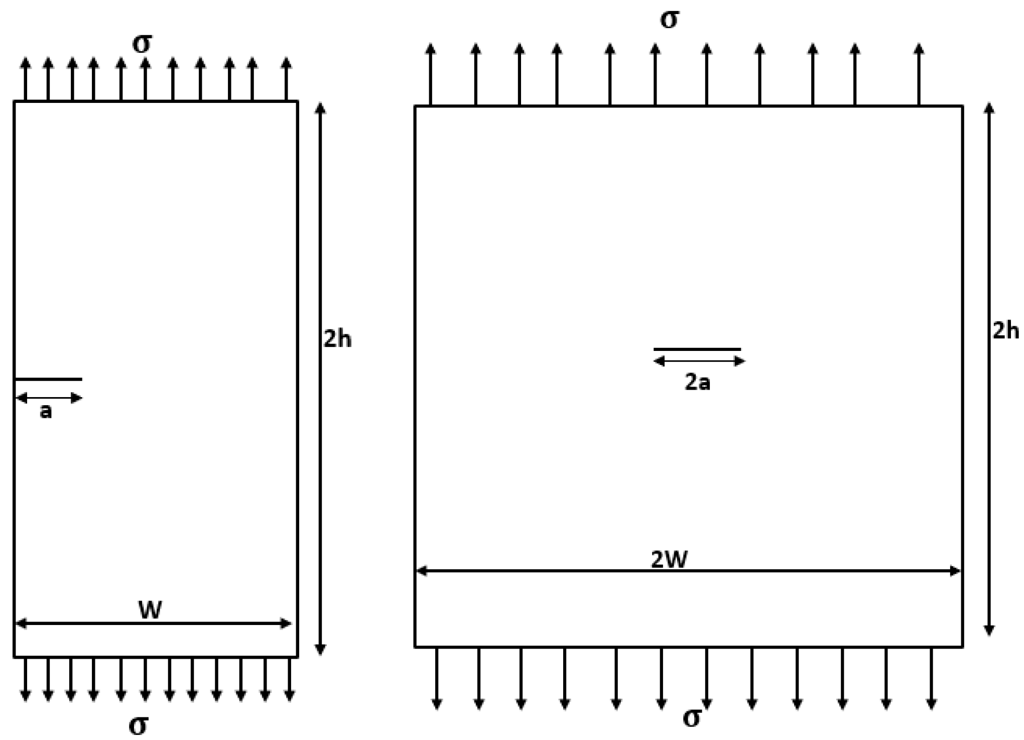
2. Models and Method

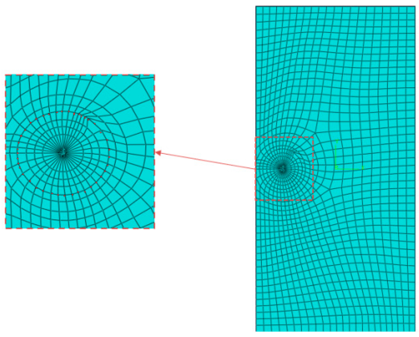
2.1. Extended Iso-Geometric Analysis (IGA)

IGA use Non-Uniform Rational B-Splines (NURBS) as a discretization method for analysis. The IGA can produce correct results even with large meshes, whereas the finite element technique (FEM) requires refining. B-splines are defined from a knot vector. A knot vector is a set of increasing reals defined in the parameter space.
Ξ = ξ 1 , ξ 2 , , ξ n + p + 1   ;   ξ i < ξ i + 1
where ξ i R is the ith knot, i = 1, 2, …, n + p + 1, p is the polynomial order, and n is the number of basis functions. The B-spline basis functions are defined by the following:
For p = 0,
N i , 0 = 1 ξ i   ξ < ξ i + 1 0 o t h e r w i s e
For p = 1, 2, …,
N i , p ξ = ξ ξ i ξ i + p ξ i N i , p 1 + ξ i + p + 1 ξ ξ i + p + 1 ξ i + 1 N ( ξ ) i + 1 , p 1
The properties of B-spline basis function are as follows:
  • Partition of unity: i = 1 n N i , p ξ = 1 ;
  • The continuity of the basic functions is C p 1 , where p is the polynomial degree and m is the multiplicity of the knot;
  • The support of N i , p is included in [ ξ i , ξ i + p + 1 ] ;
  • The first derivative of a B-spline basis function.
d d ξ N i , p ξ = p ξ i + p ξ i N i , p 1 ξ p ξ i + p + 1 ξ i + 1 N i + 1 , p 1 ( ξ )
NURBS are built from B-spline functions by assigning a weight to each control point. NURBS are still the dominating engineering design technology. T-splines are recent technical generalizations based on NURBS that can be somewhat unstructured. T-splines are a NURBS superset, and their local refinement features enable solving the gap/overlap problems of intersecting NURBS surfaces more easily.
R i p ξ = N i , p ( ξ ) w i i = 1 n N i , p ( ξ ) w i
where N i , p ( ξ ) is the ime B-Spline function of degree p; w i : weight. The basic function and the control points B i are combined linearly to create the B-spline curve:
C ξ = i = 1 n N i , p B i
There are three types of refinement in iso-geometric analysis:
  • Knot insertion is the h-refinement; this refinement changes the basic functions N i , p defined on a node vector, to a new basis Ň i , p :
    i n N i , p . P i = i n + 1 Ň i , p P i
  • Degree elevation entails raising the polynomial order of the basic functions, and well nodes are added to the edge. The added values are values that already exist in the initial node vector, they are the p-refinement.
  • k-refinement involves refinement steps h and p [22,23], and increases continuity as well as polynomial order.
Extended Isogeometric analysis X-IGA is a coupling between the extended finite element method X-FEM [23] and the IGA. The IGA aims to present the exact geometry, and X-FEM to model the crack by enrichment. X-IGA extends the capabilities of IGA by providing precise analysis of complicated structural phenomena such as fracture propagation and deformation, which are critical in materials science and engineering.
The level set technique is used for enrichment, which identifies the position of the crack and the crack tip in order to enrich it with the necessary function. Sethian and Osher [23] proposed the level set method as a numerical method for tracking the evolution of interfaces and shapes. The LSM is a great complement to the X-FEM because it informs you where and how to enrich:
u ξ = i n R i ( ξ ) u i + j n c f R j ξ [ H ξ H ( ξ j ) ] a j + k n c t R k ( ξ ) α = 1 4 [ ψ α ( ξ ) ψ α ( ξ ) ] b α k
where Ri is the basis function; n c f is the number of nodes enriched by the Heaviside function; n c t is the number of nodes enriched by the functions of enrichments in the crack tip; ψ α : the functions of enrichments in the crack tip and H is the Heaviside function,
H ξ = + 1   φ ξ > 0 0   φ ξ = 0 1   φ ξ < 0 ,
u i , a j , b α k represent the classical, discontinuous, and singular degrees of freedom, respectively.

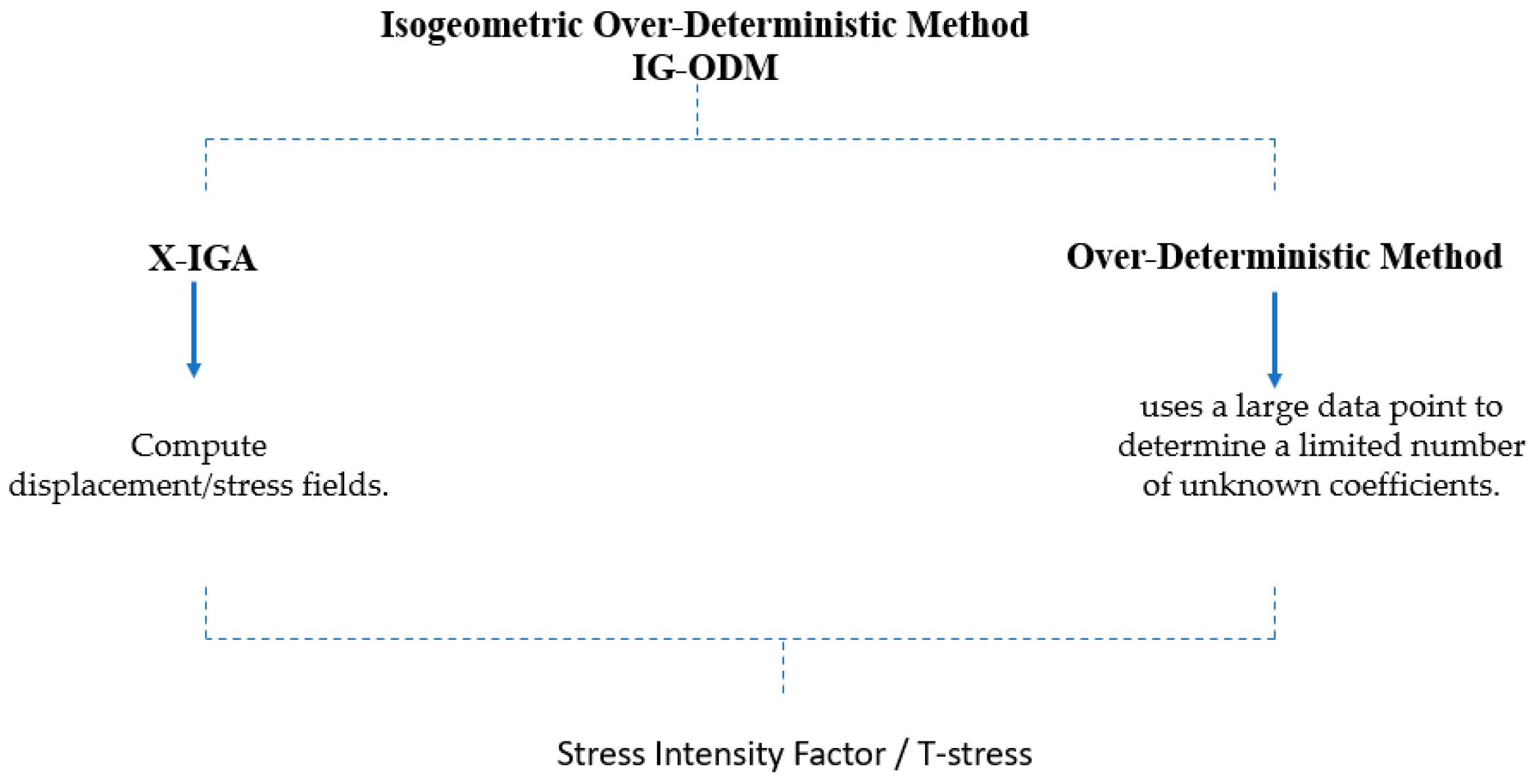
2.2. Iso-Geometric Over-Deterministic Method
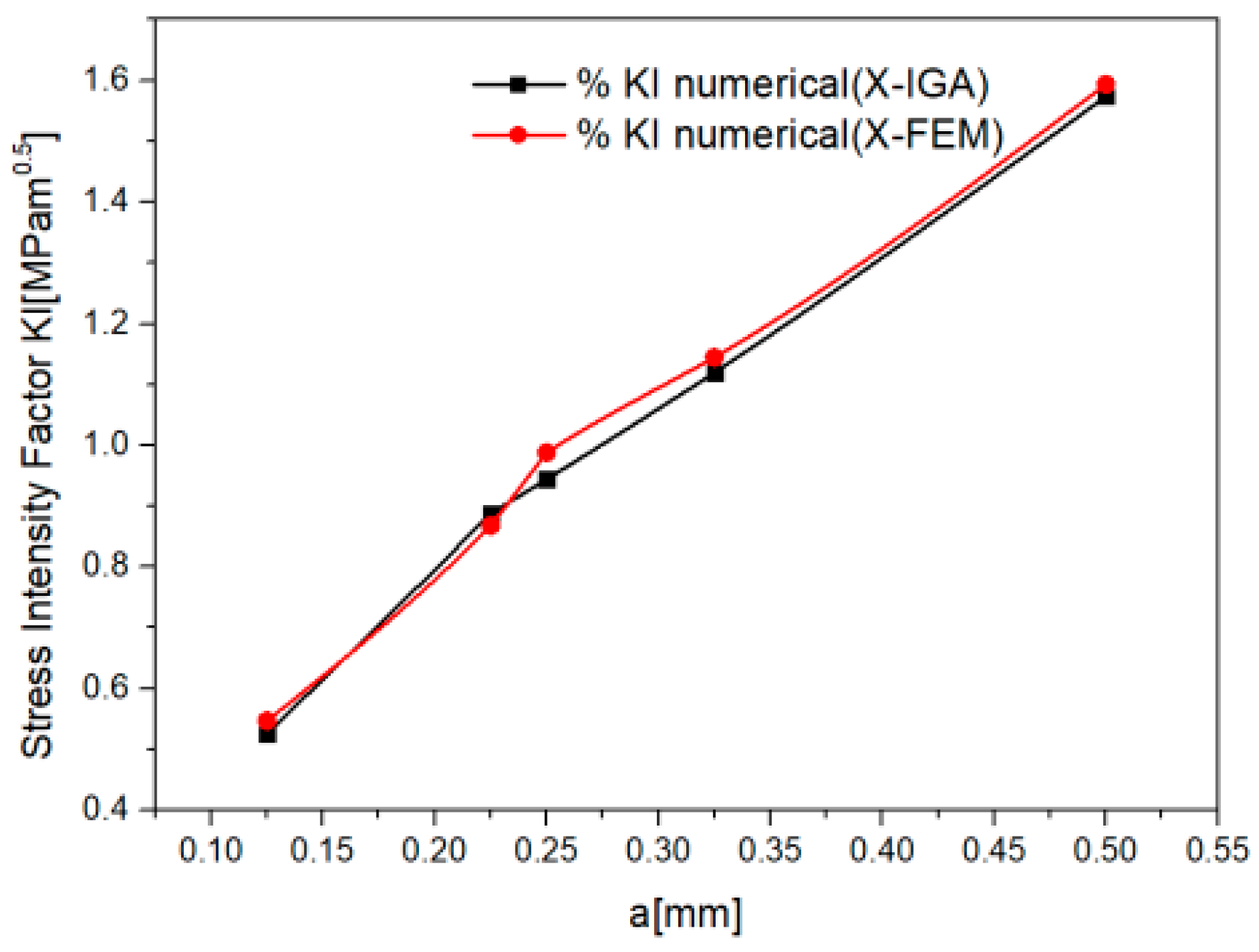
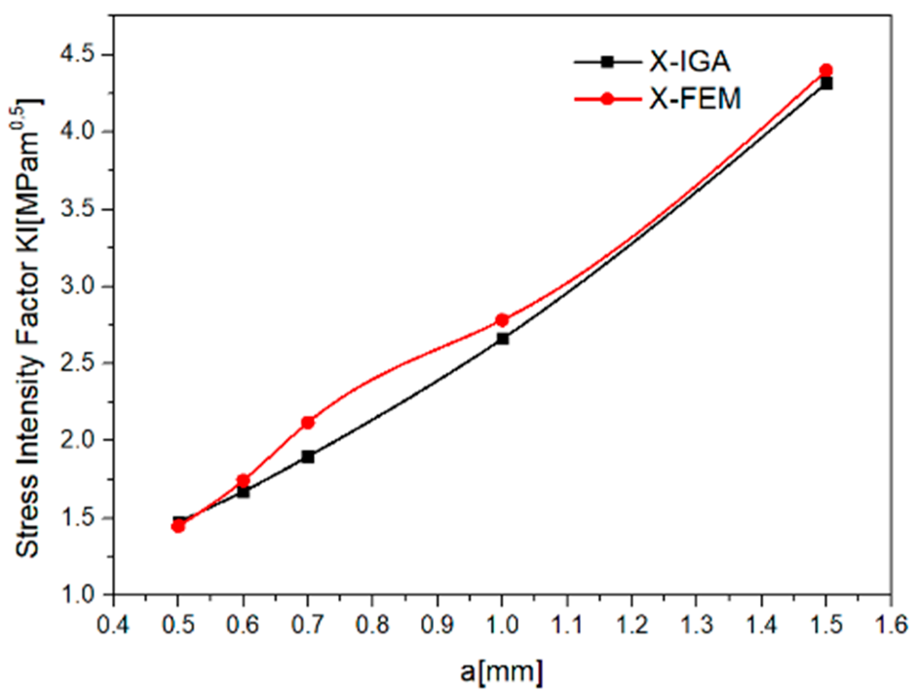
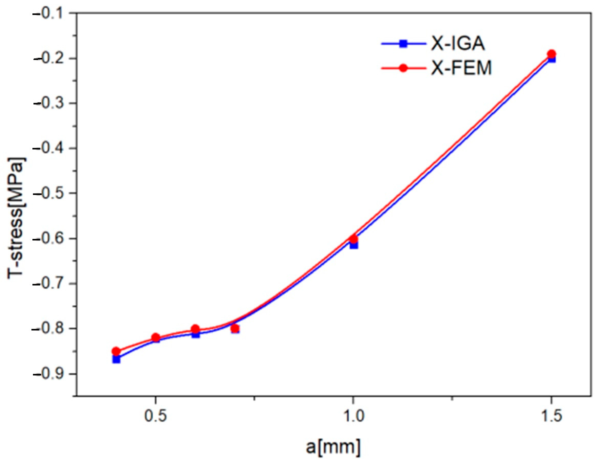
IG-ODM is based on the calculation of displacement and stress around the crack point (Figure 1).
These results are then introduced into the Williams expression [24], yielding a set of over-deterministic equations. The least squares method [13] is used to solve these equations and obtain the crack parameters. In our study, we utilize the X-IGA numerical technique to obtain a more precise displacement field. By improving the precision of the displacement field, we can achieve more accurate parameter computation using the ODM technique in Figure 2.
The displacement field at the crack tip:
u = n = 0 N A n 2 μ r n / 2 × k + n 2 + 1 n cos n 2 θ n 2 cos n 2 2 θ + n = 0 M B n 2 μ r n / 2 × k n 2 + 1 n sin n 2 θ n 2 sin n 2 2 θ v = n = 0 N A n 2 μ r n / 2 × k n 2 1 n sin n 2 θ n 2 sin n 2 2 θ + n = 0 M B n 2 μ r n / 2 × k n 2 + 1 n cos n 2 θ n 2 cos n 2 2 θ
u and v are the displacement in x and y directions, μ = E 2 ( 1 + ϑ ) is the shear modulus, and k the Kolosov constant.
Equation (6) can be written as
u = n N A n f n 1 r , θ + n M B n f n 2 ( r , θ ) ;     v = n N A n g n 1 r , θ + n M B n g n 2 ( r , θ )    
f n 1 r , θ ,   f n 2 r , θ , g n 1 r , θ   a n d   g ( r , θ ) are functions of coordinates r and θ ; An and Bn are related to the crack parameters, SIF K 1 and K 2 , T-stress and the higher order parameters.
K 1 = 2 π A 1     ,   T = 4 A 2 .
The set of equations can be represented as follows, if there are k nodes near the crack:
                                                                U 2 L = C 2 L ( N + M + 2 ) X ( N + M + 2 ) .
The terms An and Bn are associated with the mode I and mode II components of deformation, respectively. For n = 0, the displacement components can be written as
                                                            u 0 = f 0 A 0 = κ + 1 2 μ A 0 ;   v 0 = g 0 B 0 = κ + 1 2 μ B 0 .
Equation (12) is the rigid body translation of the crack tip that is independent of the position of the points. κ is the Kolosov constant, and μ is the shear modulus.
The term B2 refers to the crack’s rigid body rotation with regard to the crack tip.
u = κ + 1 2 μ B 2 r s i n θ ;   v = κ + 1 2 μ B 2 c o s θ
The amplitude of the crack’s rigid body rotation is equal to the angle formed by the initial direction of the fracture and the bisector of crack faces following structural deformation. [U] contains the nodal displacement calculated by extended iso-geometric analysis X-IGA, so
u ξ = i n R i ( ξ ) u i + j n c f R j ξ [ H ξ H ( ξ j ) ] a j + k n c t R k ( ξ ) α = 1 4 [ ψ α ( ξ ) ψ α ( ξ ) ] b α k
The second term in the equation represents the enrichment of the discontinuity, and the third to model the crack tip, and the NURBS basic function R i are presented by Equations (3) and (4). [C] includes the values of functions f ( r , θ ) and g ( r , θ ) at the nodal position.
f n , r , θ = n 2 r n 2 1 [ ( 2 + n 2 + 1 n cos n 2 1 θ n 2 1 c o s ( n 2 3 ) θ ]
g n , r , θ = n 2 r n 2 1 [ ( 2 n 2 1 n cos n 2 1 θ + n 2 1 c o s ( n 2 3 ) θ ]
[X] includes the coefficients of the Williams expansion, unknown parameters, SIF, T-stress and higher-order terms:
C T U = C T C X ;   X = ( C T C ) 1 C T U .
The least-squares approach is used to calculate the unknown parameters.

3. Results

In order to investigate the crack parameters in pure mode I using IG-ODM, we conducted tests on two geometries: the SECT and the CCT, as shown in Figure 3. The geometric dimensions used in the test were h = w = 4 , a = 1 and σ = 1   M P a [13]. For the calculations, we selected the Young’s modulus (E) as 1000 MPa and the Poisson’s ratio (v) as 0.3.
In the case of the CCT specimen, we employed 1600 control points, 1444 nodes, and a polynomial order of p = q = 3. For the SECT specimens, we used 1200 nodes and 1352 control points (Figure 4). the type of crack is sharp. The X-IGA method was utilized to compute the displacement fields, while the ODM (over-deterministic method) was employed to calculate the higher-order parameters in the Williams series.
The input parameters (the polynomial order, control points, and node vectors) are the initial phase in the MATLAB 2020 software computing approach for the X-IGA implementation. Secondly, the crack data are introduced. For determining the crack position and enrichment points, we employed the level set approach. Then, the boundary conditions, nodal force vector, and stiffness matrix are determined.
After obtaining the displacement and stress fields using X-IGA, we select a ring around the crack tip (as shown in Figure 4). The selected ring satisfies the condition a/4 < r < a/2, where a is the crack length. In order to ensure the solvability of the system, the number of equations must be greater than twice the number of unknowns, following the inequality 2k ≥ 2(N + M + 2) [14], where K is the number of nodes used to compute SIF and T-stress; and N and M are the numbers of terms used in the Williams expression for mode 1 and 2, respectively.
We have selected 52 nodes to calculate the SIF and T-stress, denoted as K = 52. In our calculation, we consider N = 10 terms in the Williams series for Mode I crack analysis. A MATLAB algorithm is used to compute the unknown parameters, employing the least-squares method [25].
Table 1 and Table 2 present the SIF K1 and T-stress for the Mode I crack under static loading. To evaluate the accuracy of the proposed method, we calculate the error using the formula: K I G O D M K i K i × 100 . The distribution of stress intensity factor by X-IGA et X-FEM at the crack tip as a function of crack size for the CCT and SECT specimen, as illustrated in Figure 5 and Figure 6.
For the CCT specimen, the IG-ODM yields a SIF of 1.888 M P a m , with an inaccuracy of 1.911% compared to reference [13] and 1.799% compared to reference [26]. The T-stress obtained is −1.1037 MPa, with an error of less than 0.64% (Table 1). These results demonstrate that the proposed method exhibits errors ranging from 0.06% to 2% when compared to other research studies.
Table 2 compares the SIF and T-stress results obtained by IG-ODM for SECT specimens to those obtained by previous studies. The error is less than 0.26 percent for SIF and less than 2 percent for T-stress.
In Figure 5, which pertains to the CCT geometry, the SIF obtained from the X-IGA method shows an upward trend as the crack size (a) increases. This indicates that larger cracks result in higher stress intensity at the crack tip.
Similarly, Figure 6 presents the SIF variation for the SECT geometry. Here as well, the SIF obtained from the X-IGA method exhibits a rising pattern with increasing crack size (a). This implies that larger cracks lead to higher stress intensity in the SECT specimen.
Figure 7 represents the variation of T-stress by stress different method using X-IGA and X-FEM as a function of the size of the crack a; the absolute value of T decreases with the increase in a.

4. Discussion and Conclusions

The paper discusses the fracture parameters SIF (stress intensity factor) and T-stress using a novel IG-ODM (Isogeometric Over-Deterministic Method) approach.
Most approaches concentrate primarily on SIF extraction, with little focus devoted to T-stress and higher-order terms. The objective of this work is to more precisely determine SIF and T-stress using the IG-ODM approach, and evaluate its accuracy compared to other methods. The approach involves computing the displacement and stress around the crack using extended isogeometric analysis X-IGA, incorporating the results into the Williams expression, and obtaining crack parameters through the least-squares method.
Computing fracture parameters provides valuable insights into the crack, its propagation, and the stability of its path. Ensuring the accuracy of these computations is crucial, and X-IGA has proven to be effective in various studies. For instance, Yin et al. [27] used the X-IGA to study static crack problems in the two-dimensional model, achieving an error of e K 1 = 0.1406 % for an edge-crack plate with 656 control points, and obtained excellent results for K1 for the center crack. Additionally, a comparison between X-IGA and X-FEM demonstrated that X-IGA is more accurate than X-FEM with fewer elements and less computation time [28]. El Fakkoussi et al. [29] emphasized the importance and accuracy of X-IGA compared to FEM and X-FEM in computing SIF at the point of an external crack in an arc under internal pressure. Ghorashi et al. [20] demonstrated that X-IGA provides computation times twice as fast as X-FEM. Even with a large mesh, the X-IGA approach is more accurate than the finite element method [10], so the number of elements is chosen according to calculation time, in order to reduce costs.
Leveraging these advantages, the paper aimed to achieve greater precision in computing the displacement field using X-IGA, followed by the application of ODM (Over-Deterministic Method), which has also proven to be effective in computing the coefficients of the Williams series. Accurate results were obtained, demonstrating that IG-ODM is an efficient method for computing crack characteristics such as SIF and T-stress. We selected the distance of the ring from the fracture tip to verify a/4 < r < a/2, because of the relatively substantial numerical errors that exist in nodes extremely near the crack tip.
The ODM approach, based on the stress field, was originally proposed by Cheng Hou et al. [12] for the computation of SIF and T-stress; they achieved accurate results for SECT (K_1 = 2.6525 MPa√m, T = −0.5984 MPa) and CCT (K_1 = 1.9252 MPa√m, T = −1.1044 MPa), with an error of less than 1.124% compared to other research. YufeiLi et KanZheng [14] also examined the SIF and T-stress using ODM based on the displacement field, employing the nodal findings of X-FEM analysis. The effectiveness of the FEODM (Finite Element Over-Deterministic Method) was demonstrated in the work of R. Ayatollahi et al. [30]. The benefit of the IG-ODM approach we have described compared to other ways employing ODM; the geometry and the crack are precisely represented [31,32,33] using the X-IGA method.
The observed negative T-value implies a stable fracture propagation direction, while a positive T-value indicates an unstable direction, as discussed by Cotterell et al. [34]. Another study [35,36,37,38,39,40,41] showed that a negative T-value reduced the crack initiation angle while a positive T value raises it.
The IG-ODM has yielded significant and accurate results, which can be attributed to the accuracy of X-IGA extended isogeometric analysis as compared to the finite element approach (FEM), as well as the efficacy of the over-deterministic ODM approach, which calculates a limited number of unknown coefficients from a large number of data points [42]. In this work, a coupling of the X-IGA method with the over-deterministic method (ODM) are proposed to calculate the T-stress and the SIF at the crack tip for mode Ι. This work aims to take advantage of the benefits of X-IGA and ODM. IG-ODM is based on the calculation of stress and displacement fields by X-IGA to better present the geometry and enrich the crack, thereby introducing the results into the Williams iv expression, from which a set of deterministic equations is obtained whose solution is obtained by the least-squares method.
  • The T-stress is introduced to enrich SIF, in a better presentation of the crack.
  • The SIF and T-stress are determined using IG-ODM, which is an efficient method for computing fracture parameters.
  • The IG-ODM approach proves to be more efficient when the displacement field is accurately determined, utilizing a more precise numerical method such as X-IGA.
  • IGA, as a technology, allows for interaction with CAD systems, leading to improved solution accuracy and reduced computational costs.
  • In order to obtain accurate results using IG-ODM, it is essential that the number of crack parameters exceeds the number of nodal displacements determined by X-IGA.
  • Because of the relatively significant numerical errors that exist in nodes that are very near to the fracture tip, it is better to obtain the essential data from nodes that are further away from the crack tip, and it is preferable to select nodes from a particular ring.
The studied subject allows for further development and obtaining new results in the field. We expect to develop a new project where the authors will employ IG-ODM to investigate cracking problems in complex geometries, demonstrating its potential for accurate analysis and understanding in such scenarios.

Author Contributions

Conceptualization, K.Y., A.E., H.M., A.E.A., M.L.S. and S.V.; methodology, K.Y., A.E., H.M. and A.E.A.; validation, K.Y., A.E., H.M., A.E.A., M.L.S. and S.V.; formal analysis, K.Y., A.E., H.M. and A.E.A.; investigation, K.Y., A.E., H.M. and A.E.A.; writing—original draft preparation, K.Y., A.E., H.M. and A.E.A.; writing—review and editing, K.Y., A.E., H.M., A.E.A., M.L.S. and S.V.; supervision, K.Y., A.E., H.M., A.E.A., M.L.S. and S.V. All authors have read and agreed to the published version of the manuscript.

Funding

The APC was funded by Transilvania University of Brasov.

Data Availability Statement

Not applicable.

Conflicts of Interest

The authors declare no conflict of interest.

References

  1. Cotterell, B. Notes on the paths and stability of cracks. Int. J. Fract. 1966, 2, 526–533. [Google Scholar] [CrossRef]
  2. Nejati, M.; Ghouli, S.; Ayatollahi, M.R. Crack tip asymptotic fields in anisotropic planes: Importance of higher order terms. Appl. Math. Model. 2021, 91, 837–862. [Google Scholar] [CrossRef]
  3. Matvienko, Y.G. The effect of crack-tip constraint in some problems of fracture mechanics. Eng. Fail. Anal. 2020, 110, 104413. [Google Scholar] [CrossRef]
  4. Jayadevan, K.R.; Narasimhan, R.; Ramamurthy, T.S.; Dattaguru, B. Effect of T-stress and loading rate on crack initiation in rate sensitive plastic materials. Int. J. Solids Struct. 2002, 39, 1757–1775. [Google Scholar] [CrossRef]
  5. Ayatollahi, M.R.; Hashemi, R. Computation of stress intensity factors (KI, KII) and T-stress for cracks reinforced by composite patching. Compos. Struct. 2007, 78, 602–609. [Google Scholar] [CrossRef]
  6. Sherry, A.H.; France, C.C.; Goldthorpe, M.R. Compendium of t-stress solutions for two and three dimensional cracked geometries. Fatigue Fract. Eng. Mater. Struct. 1995, 18, 141–155. [Google Scholar] [CrossRef]
  7. Shahani, A.R.; Tabatabaei, S.A. Effect of T-stress on the fracture of a four point bend specimen. Mater. Des. 2009, 30, 2630–2635. [Google Scholar] [CrossRef]
  8. Fayed, A.S. Numerical Analysis of Crack Initiation Direction in Quasi-brittle Materials: Effect of T-Stress. Arab. J. Sci. Eng. 2019, 44, 7667–7676. [Google Scholar] [CrossRef]
  9. Miao, X.T.; Zhou, C.Y.; Lv, F.; He, X.H. Three-dimensional finite element analyses of T-stress for different experimental specimens. Theor. Appl. Fract. Mech. 2017, 91, 116–125. [Google Scholar] [CrossRef]
  10. Yakoubi, K.; Montassir, S.; Moustabchir, H.; Elkhalfi, A.; Pruncu, C.I.; Arbaoui, J.; Umar Farooq, M. An Extended Finite Element Method (XFEM) Study on the Elastic T-Stress Evaluations for a Notch in a Pipe Steel Exposed to Internal Pressure. Mathematics 2021, 9, 507. [Google Scholar] [CrossRef]
  11. Yang, B.; Ravi-Chandar, K. Evaluation of elastic T-stress by the stress difference method. Eng. Fract. Mech. 1999, 64, 589–605. [Google Scholar] [CrossRef]
  12. Hou, C.; Wang, Z.; Jin, X.; Ji, X.; Fan, X. Determination of SIFs and T-stress using an over-deterministic method based on stress fields: Static and dynamic. Eng. Fract. Mech. 2021, 242, 107455. [Google Scholar] [CrossRef]
  13. Ayatollahi, M.R.; Nejati, M. An over-deterministic method for calculation of coefficients of crack tip asymptotic field from finite element analysis: Calculating coefficients of crack tip asymptotic field from FE analysis. Fatigue Fract. Eng. Mater. Struct. 2011, 34, 159–176. [Google Scholar] [CrossRef]
  14. Li, Y.; Zheng, K. Crack tip asymptotic field coefficients analyses based on extended finite element method using over-deterministic displacement field fitting method. Theor. Appl. Fract. Mech. 2021, 113, 102971. [Google Scholar] [CrossRef]
  15. Cuong-Le, T.; Nguyen, K.D.; Nguyen-Trong, N.; Khatir, S.; Nguyen-Xuan, H.; Abdel-Wahab, M. A three-dimensional solution for free vibration and buckling of annular plate, conical, cylinder and cylindrical shell of FG porous-cellular materials using IGA. Compos. Struct. 2021, 259, 113216. [Google Scholar] [CrossRef]
  16. Shafei, E.; Faroughi, S.; Rabczuk, T. Nonlinear transient vibration of viscoelastic plates: A NURBS-based isogeometric HSDT approach. Comput. Math. Appl. 2021, 84, 1–15. [Google Scholar] [CrossRef]
  17. Hinz, J.; Jaeschke, A.; Möller, M.; Vuik, C. The role of PDE-based parameterization techniques in gradient-based IGA shape optimization applications. Comput. Methods Appl. Mech. Eng. 2021, 378, 113685. [Google Scholar] [CrossRef]
  18. Hou, W.; Jiang, K.; Zhu, X.; Shen, Y.; Hu, P. Extended isogeometric analysis using B++ splines for strong discontinuous problems. Comput. Methods Appl. Mech. Eng. 2021, 381, 113779. [Google Scholar] [CrossRef]
  19. Fathi, F.; de Borst, R. Geometrically nonlinear extended isogeometric analysis for cohesive fracture with applications to delamination in composites. Finite Elem. Anal. Des. 2021, 191, 103527. [Google Scholar] [CrossRef]
  20. Ghorashi, G.; Valizadeh, N.; Mohammadi, S. Extended isogeometric analysis for simulation of stationary and propagating cracks. Int. J. Numer. Methods Eng. 2012, 89, 1069–1101. [Google Scholar] [CrossRef]
  21. Yadav, A.; Godara, R.K.; Bhardwaj, G. A review on XIGA method for computational fracture mechanics applications. Eng. Fract. Mech. 2020, 230, 107001. [Google Scholar] [CrossRef]
  22. Nguyen, V.P.; Bordas, S.P.A.; Rabczuk, T. Isogeometric analysis: An overview and computer implementation aspects. Math. Comput. Simul. 2015, 117, 89–116. [Google Scholar] [CrossRef]
  23. Montassir, S.; Yakoubi, K.; Moustabchir, H.; Elkhalfi, A.; Rajak, D.K.; Pruncu, C.I. Analysis of Crack Behaviour in Pipeline System Using FAD Diagram Based on Numerical Simulation under XFEM. Appl. Sci. 2020, 10, 6129. [Google Scholar] [CrossRef]
  24. Williams, M.L. On the Stress Distribution at the Base of a Stationary Crack. (10 June 2021)ASME. J. Appl. Mech. 1957, 24, 109–114. [Google Scholar] [CrossRef]
  25. Sanford, R.J. Application of the least-squares method to photoelastic analysis: Two global methods for determining certain key parameters from full-field fringe patterns based on the method of least squares are presented. Exp. Mech. 1980, 20, 192–197. [Google Scholar] [CrossRef]
  26. Xiao, Q.Z.; Karihaloo, B.L.; Liu, X.Y. Direct determination of SIF and higher order terms of mixed mode cracks by a hybrid crack element. Int. J. Fract. 2004, 125, 207–225. [Google Scholar] [CrossRef]
  27. Bui, Q.; Zheng, X.; Gu, S. Static and dynamic fracture analysis in elastic solids using a multiscale extended isogeometric analysis. Eng. Fract. Mech. 2019, 207, 109–130. [Google Scholar] [CrossRef]
  28. Nguyen-Thanh, N.; Valizadeh, N.; Nguyen, M.N.; Nguyen-Xuan, H.; Zhuang, X.; Areias, P.; Zih, Y.; Bazilevsg, L.; De Lorenzisa, T.; Rabczuk, T. An extended isogeometric thin shell analysis based on Kirchhoff–Love theory. Comput. Methods Appl. Mech. Eng. 2015, 284, 265–291. [Google Scholar] [CrossRef]
  29. El Fakkoussi, S.; Moustabchir, H.; Elkhalfi, A.; Pruncu, C.I. Application of the Extended Isogeometric Analysis (X-IGA) to Evaluate a Pipeline Structure Containing an External Crack. J. Eng. 2018, 2018, 4125765. [Google Scholar] [CrossRef]
  30. Ayatollahi, M.R.; Nejati, M.; Ghouli, S. The finite element over-deterministic method to calculate the coefficients of crack tip asymptotic fields in anisotropic planes. Eng. Fract. Mech. 2020, 231, 106982. [Google Scholar] [CrossRef]
  31. Lai, W.; Yu, T.; Bui, T.Q.; Wang, Z.; Curiel-Sosa, J.L.; Das, R.; Hirose, S. 3-D elasto-plastic large deformations: IGA simulation by Bézier extraction of NURBS. Adv. Eng. Softw. 2017, 108, 68–82. [Google Scholar] [CrossRef]
  32. Montassir, S.; Moustabchir, H.; Elkhalfi, A.; Scutaru, M.L.; Vlase, S. Fracture Modelling of a Cracked Pressurized Cylindrical Structure by Using Extended Iso-Geometric Analysis (X-IGA). Mathematics 2021, 9, 2990. [Google Scholar] [CrossRef]
  33. Kapoor, H.; Kapania, R.K. Geometrically nonlinear NURBS isogeometric finite element analysis of laminated composite plates. Compos. Struct. 2012, 94, 3434–3447. [Google Scholar] [CrossRef]
  34. Cotterell, A. Slightly curved or kinked cracks. Int. J. Fract. 1980, 16, 155–169. [Google Scholar] [CrossRef]
  35. Codarcea-Munteanu, L.; Marin, M.; Vlase, S. The study of vibrations in the context of porous micropolar media thermoelasticity and the absence of energy dissipation. J. Comput. Appl. Mech. 2023, 54, 437–454. [Google Scholar] [CrossRef]
  36. Kim, J.-H.; Paulino, G.H. T-stress, mixed-mode stress intensity factors, and crack initiation angles in functionally graded materials: A unified approach using the interaction integral method. Comput. Methods Appl. Mech. Eng. 2003, 192, 1463–1494. [Google Scholar] [CrossRef]
  37. Shah, P.D.; Tan, C.L.; Wang, X. T-stress solutions for two-dimensional crack problems in anisotropic elasticity using the boundary element method. Fatigue Fract. Eng. Mater. Struct. 2006, 29, 343–356. [Google Scholar] [CrossRef]
  38. Sladek, J.; Sladek, V. Evaluation of the Elastic T-stress in Three-dimensional Crack Problems Using an Integral Formula. Int. J. Fract. 2000, 101, 47–52. [Google Scholar] [CrossRef]
  39. Wang, X. Elastic T-stress solutions for semi-elliptical surface cracks in finite thickness plates. Eng. Fract. Mech. 2003, 70, 731–756. [Google Scholar] [CrossRef]
  40. Koubaiti, O.; Elkhalfi, A.; El-Mekkaoui, J.; Mastorakis, N. Solving the problem of constraints due to Dirichlet boundary conditions in the context of the mini element method. Int. J. Mech. 2020, 14, 12–22. [Google Scholar]
  41. El Ouadefli, L.; El Moutea, O.; El Akkad, A.; Elkhalfi, A.; Vlase, S.; Scutaru, M.L. Mixed Isogeometric Analysis of the Brinkman Equation. Mathematics 2023, 11, 2750. [Google Scholar] [CrossRef]
  42. El Ouadefli, L.A.; El Akkad, S.A.; El Moutea, O.; Moustabchir, H.; Elkhalfi, A.; Scutaru, L.M.; Muntean, R. Numerical simulation for Brinkman system with varied permeability tensor. Mathematics 2022, 10, 3242. [Google Scholar] [CrossRef]
Figure 1. Stresses in a Cartesian reference frame.
Mathematics 11 04293 g001
Figure 2. Diagram of the proposed IG-ODM method.
Mathematics 11 04293 g002
Figure 3. SECT and CCT.
Mathematics 11 04293 g003
Figure 4. Meshes of SECT and CCT specimen.
Mathematics 11 04293 g004
Figure 5. Distribution of stress intensity factor by X-IGA et X-FEM at the crack tip as a function of crack size for CCT specimen.
Mathematics 11 04293 g005
Figure 6. Distribution of stress intensity factor by X-IGA et X-FEM at the crack tip as a function of crack size for SECT specimen.
Mathematics 11 04293 g006
Figure 7. T-stress calculated by stress different method SDM for SECT specimens.
Mathematics 11 04293 g007
Table 1. SIF and T-stress for CCT specimens.
K 1   [ M P a m ,] E r r o r = K I G O D M K i K i × 100 T-Stress [MPa] Error = T I G O D M T i T i × 100
IG-ODM1.8884---−1.1037---
Ref. [13]1.92521.911%−1.10440.06%
Ref. [26]1.9231.799%−1.11160.64%
Table 2. SIF and T-stress for SECT specimens.
K 1   [ M P a m ,] E r r o r = K I G O D M K i K i × 100 T-Stress [MPa] Error = T I G O D M T i T i × 100
IG-ODM2.6631 −0.6129---
Abaqus Contour Integral2.6570.2%−0.60082%
Ref. [13]2.65600.267%−0.60281.6%
Disclaimer/Publisher’s Note: The statements, opinions and data contained in all publications are solely those of the individual author(s) and contributor(s) and not of MDPI and/or the editor(s). MDPI and/or the editor(s) disclaim responsibility for any injury to people or property resulting from any ideas, methods, instructions or products referred to in the content.

