Article

Adaptive Variable-Damping Impedance Control for Unknown Interaction Environment

1
School of Mechanical and Electrical Engineering, University of Electronic Science and Technology of China, Chengdu 611731, China
2
Shenzhen Institute for Advanced Study, University of Electronic Science and Technology of China, Shenzhen 518000, China
3
Department of Informatics, University of Oslo, 0313 Oslo, Norway
*
Author to whom correspondence should be addressed.
Mathematics 2023, 11(24), 4961; https://doi.org/10.3390/math11244961
Submission received: 6 November 2023 / Revised: 12 December 2023 / Accepted: 13 December 2023 / Published: 14 December 2023
(This article belongs to the Special Issue Mathematical Modeling for Parallel and Distributed Processing)

Abstract

:
Aiming at the force-tracking error phenomenon of impedance control in an unknown surface environment, an adaptive variable-damping impedance control algorithm is proposed, and the stability and convergence of the algorithm are deduced. An adaptive-law selection rule is proposed to aim at the phenomenon that the adaptive parameters are too large to cause the system oscillation and overshoot and too small to cause the adaptive line variation in the curved surface environment. Finally, experiments conclude that the impedance control based on the adaptive variable-damping algorithm has a better force-tracking effect than the ordinary impedance control in the curved surface environment where the contact surface between the end-effector of the manipulator and the atmosphere is unknown.

1. Introduction

With the increasing demand for manipulators in practical applications, achieving a noncontact control of manipulators, such as in painting and welding, has become possible through path planning and trajectory control, enabling position tracking in free space [1,2]. However, executing complex tasks that involve interactions with complex external environments, such as surface polishing, burr removal, and grinding, requires the manipulator’s end-effector to not only precisely follow a target trajectory but also deliver specified operational forces to the external environment upon reaching the designated task position. This necessitates accurate force tracking, which is crucial for successfully completing interactive operations [3,4,5]. However, the contact positions on the surfaces of these work objects are often unknown. Employing methods like a complete contact position measurement, trajectory planning, or surface teaching for surface force control in the manipulator often involves extensive computations and repetitive work, lacking universality when surface objects are replaced [6,7,8]. Additionally, traditional impedance control methods applied to surface environments often exhibit an increasing force tracking error with increasing surface curvature, making it challenging to achieve the desired force tracking and posing a risk of damaging the workpieces. To address these issues, the development of an adaptive force control algorithm for manipulators capable of adapting to surface environments is necessary [9].
Currently, manipulator force control technology mainly consists of three mainstream methods: passive compliance control, force/position hybrid control, and impedance control [10,11]. These methods have been widely studied and applied in the field. However, the adaptability of passive compliance control is limited when environmental parameters dynamically change, and it is primarily suitable for specific scenarios [12,13,14]. Therefore, researchers have developed a two-dimensional, iterative-learning, robust, asynchronous-switching predictive control method to enhance the system’s disturbance rejection capability and robustness through iterative learning [15]. The variable rigid–flexible center (VRCC) method, although flexible and adaptable to environmental changes, has limitations due to its large size and weight. The force/position hybrid control method relies on accurate environmental modeling and performs poorly in unknown environments. On the other hand, impedance control demonstrates robustness against environmental uncertainties [7,16,17,18]. However, the force-tracking performance of impedance control inevitably decreases when environmental parameters change dynamically.
In practical industrial settings, designing dynamic output feedback controllers based directly on the system’s output information has significant advantages [19], given the unpredictability of the system’s state. To address these issues, we propose an adaptive variable-damping impedance control methodology. Our method adapts the damping variable to achieve precise force tracking in unknown contact environments with varying geometric and dynamic parameters. The stability and convergence of the proposed methodology have been verified. In comparison to existing impedance algorithms [20,21,22,23], the adaptive algorithm we propose dynamically adjusts the impedance parameters based on a real-time perception of the environment and external force feedback. This reduces the impact of external disturbances and uncertainties on the robot system, improving its robustness and stability.
Furthermore, experimental validation demonstrates that the impedance control based on the adaptive variable-damping algorithm achieves more accurate force tracking control and path following when dealing with unknown curved contact surfaces, surpassing conventional impedance control methods [24,25]. By adjusting the impedance parameters, the manipulator’s end-effector can avoid collisions and minimize the potential risk of damage.
This paper is organized as follows: Section 2 presents some preliminary knowledge of impedance control. In Section 3, we propose the adaptive variable-damping impedance control algorithm and provide its stability analysis. Section 4 presents experimental results to demonstrate the effectiveness of the proposed method. Finally, Section 5 concludes the paper.

2. Preliminaries

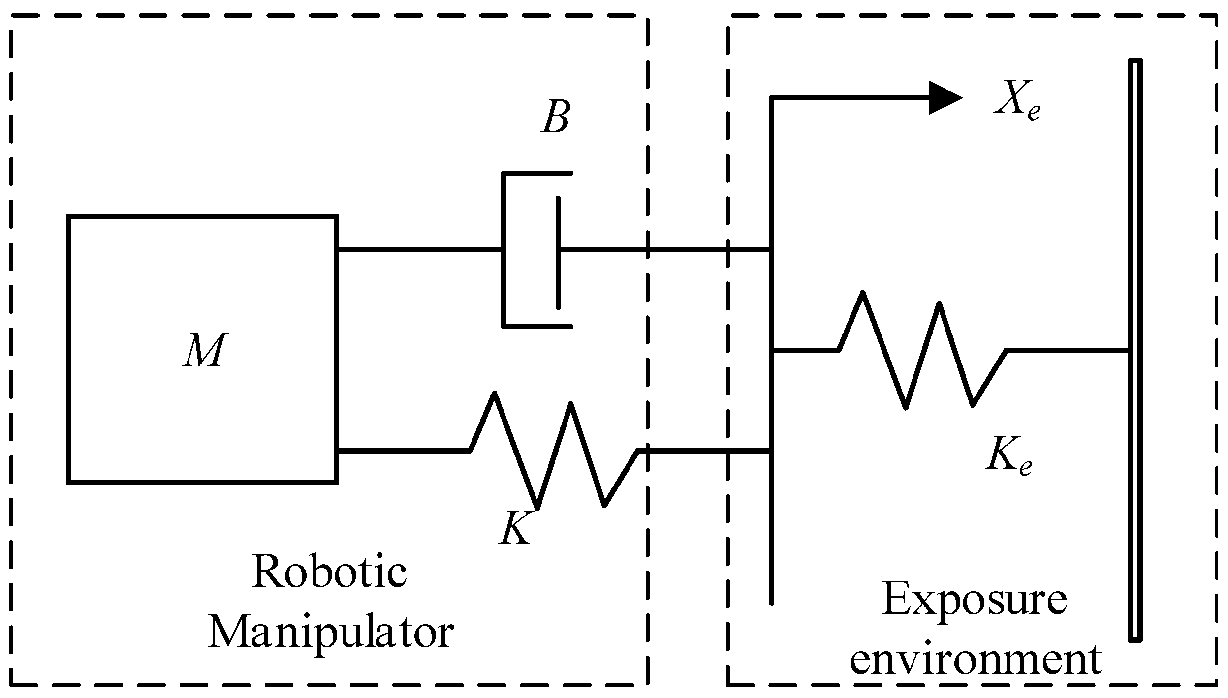
2.1. Impedance Control

The impedance control algorithm establishes the impedance relationship between force, position, and velocity. The second-order model of the mass–spring–damper system can clearly describe the dynamic relationship between the manipulator and the contact environment, as shown in Figure 1.
This dynamic model can be written as the second-order differential form
M ( X ¨ X ¨ d ) + B ( X ˙ X ˙ d ) + K ( X X d ) = F F d
where M, B, K represent the target inertia matrix, target damping matrix, and target stiffness matrix of the impedance model, respectively, and all of them are diagonal semidefinite matrices; X, X ˙ , and X ¨ are the actual position, velocity, and acceleration of the manipulator; X d , X ˙ d , and X ¨ d are the desired position, velocity, and acceleration of the manipulator, respectively. F and F d are the actual and desired force, respectively.

2.2. Impedance Control Model Analysis

The model of impedance control includes three parameters: inertia, damping, and stiffness. The three parameters have different effects on the dynamic performance of impedance control. The following explores the influence of impedance control parameters.
The general form of damping and natural frequency of the impedance control model is
G ( s ) = 1 m s 2 + 2 ξ ω n s + ω n 2
in which m is the target inertia coefficient of the impedance model, b is the target damping coefficient, k is the target stiffness coefficient, ξ = b 2 k m is the damping ratio of the model, and ω n = k m is the natural frequency of the model.
It can be seen from Equation (2) that the damping ratio of the impedance model is proportional to the damping coefficient b of the impedance model and is inversely proportional to the inertia coefficient m of the impedance model and the stiffness coefficient k of the impedance model. Therefore, to stabilize the system, b should be taken as large, m and k as small, and the large damping ratio should be maintained. The natural frequency of the impedance model is proportional to k and inversely proportional to m. When the damping ratio is fixed, the larger the natural frequency is, the better the rapidity of the second-order system is. Therefore, the impedance model’s target inertia coefficient m should be smaller. It is the opposite for the target stiffness coefficient k.
In traditional impedance control, the above impedance control parameters are fixed, but the set parameters cannot be adjusted in real time to adapt to the unknown environment, so the impedance parameters must be variable. Therefore, there should be an algorithm to adaptively adjust the impedance parameters according to environmental changes to improve the algorithm.

3. Research on Impedance Control Based on Adaptive Variable Damping Algorithm

The relationship between the impedance control model of the manipulator and the contact environment can be written as [9]:
m e ¨ + b e ˙ + k e = f f d
f = k e ( x x e )
in which e = x s d is the derivation between the actual position and the desired position of the interactive manipulator.
When the robot arm is in contact with the environment, the environment contact position is equal to the expected position X e = X d at the end of the robot manipulator. In the direction of force, the stiffness matrix k = 0 is substituted into Equation (3), and the following results are obtained:
m e ¨ + b e ˙ + k e e = f d
When the expected force f d is constant, (5) is asymptotically stable, so a good response can be obtained by dynamically adjusting the appropriate impedance parameters m and b.
When the contact surface of the manipulator’s end is curved, the contact position x e between the manipulator and the environment is unknown, Δ x e = x ˜ e x e , so only the estimated environmental part can be obtained. Then, we define:
e ˜ = e + A x e Δ x e = x ˜ e x e
where x ˜ e is the estimated value of the environment, e ˜ is the corresponding position error after increasing the estimated value.
Substituting (6) into (5), we obtain:
e ˜ f = f f d = m e ˜ ¨ + b e ˜ ˙ = m ( e ¨ + Δ x ¨ e ) + b ( e ˙ + Δ x ˙ e )
In the above equation, in the scenario of surface constant force tracking, f, e ˜ ¨ , and e ˜ ¨ are time-varying. Then, the force tracking error e ˜ f exists and changes with time. It is necessary to introduce adaptive impedance parameters to offset the force error generated during the working process [26].
From the influence of the impedance parameters of the upper section on the impedance control, it can be found that if the inertia coefficient m is changed, it is easy to cause the oscillation of the impedance control system. Therefore, to ensure the stability of the system, the damping coefficient b is adjusted adaptively, and the compensation amount Ω ( t ) is introduced:
Ω ( t ) = b e ˜ ˙ ( t ) + ε ρ ( t ) ρ ( t ) = ρ ( t λ ) + σ f ( t λ ) f d ( t λ ) b
where ε is a sufficiently small positive actual number to prevent the denominator from being 0, λ is the sampling time of the control system, and σ is the corresponding adaptive law.
Equation (7) is changed into:
e ˜ f = m e ¨ + b e ˜ ˙ + Ω = m e ˜ ¨ + b e ˜ ˙ + b Ω
The Laplace transform of Equation (9) can obtain the displacement of the end of the manipulator along the average direction of the plane, that is, the z-axis displacement of the manipulator:
Δ z = e ˜ f + b Ω m s 2 + b s
Based on the force tracking error and the adaptive law, the adaptive variable-damping impedance control can maintain a constant desired force. The control block diagram of the adaptive variable-damping impedance control is shown in Figure 2.

3.1. Stability Analysis

By substituting Equation (6) into Equation (9), we obtain:
f f d = m ( e ¨ + Δ x ¨ e ) + b ( e ˙ + Δ x ˙ e ) + b ρ ( t λ ) + σ f ( t λ ) σ f d ( t λ )
Substituting Equation (4) into (11), we have
k e ( f f d ) = m k e Δ x ¨ e + b k e Δ x ˙ e + m f ¨ + b f ˙ + b k e ρ ( t λ ) + σ k e [ f ( t λ ) f d ( t λ ) ]
Let f ˜ = k e Δ x e ; then, transform (12) into:
m f ˜ ¨ + b f ˜ ˙ = m f ¨ + b f ˙ + b k e ρ ( t λ ) + σ k e [ f ( t λ ) f d ( t λ ) ] + k e ( f f d )
Subtracting both sides of (13) by m f ¨ d + b f ˙ d ,
m r ¨ + b r ˙ = m c ¨ + b c ˙ + b k e ρ ( t λ ) + σ k e c ( t λ ) + k e c
In the equation, we have r = f ˜ f d and c = f f d .
For the adaptive law of n cycles, we have:
b ρ ( t λ ) = b ρ ( t ( n 1 ) λ ) + σ c ( t ( n 2 ) λ ) + + σ c ( t 2 λ )
The initial value of the adaptive law is set to 0, ρ ( t ( n 1 ) λ ) = 0 , and (14) is substituted into (15):
m r ¨ + b r ˙ = m c ˙ + b c ˙ + k e c + σ k e c ( t ( n 1 ) λ ) + + c ( t λ )
The Laplace transform can be written on the pair in (16) as:
c ( s ) r ( s ) = m s 2 + b s m s 2 + b s + k e + σ k e ( e ( n 1 ) λ s + + e λ s )
The characteristic equation of the system in (17) is:
m s 2 + b s + k e + σ k e e ( n 1 ) λ s + + e λ s = 0
When the system period n is large enough and the sampling time λ is small enough, we obtain:
λ m s 3 + λ b s 2 + k e λ ( 1 σ ) s + σ k e = 0
According to the Routh criterion, in order to ensure the stability of the system, the adaptive law σ should satisfy:
0 < σ < λ b λ b + m
The steady-state errors of the system are:
e s s = lim t e ( t ) = lim s 0 s E ( s ) = lim s 0 s ( c ( s ) r ( s ) ) = lim s 0 s m s 2 + b s m s 2 + b s + k e + σ k e ( e ( n + 1 ) λ s + + e λ s ) r ( s ) r ( s )
When the system step signal is r ( s ) = 1 s , (21) becomes:
e s s = lim s 0 s ( c ( s ) r ( s ) ) = 1
Then, we have:
lim s 0 s c ( s ) = 0 , lim t c ( t ) = 0
It can be seen from (23) that when t , lim s 0 s c ( s ) = 0 , lim t c ( t ) = 0 , f f d , the contact force between the end of the manipulator and the environment converges to the expected point. At the same time, it can also be proved that when the slope signal and the sinusoidal signal are input, the output is also convergent [27].

3.2. Performance Analysis and Adaptive Law Selection

In general, the position control accuracy of the industrial manipulator is very high. It can be considered that the position command of the industrial manipulator is equal to the actual position of the manipulator, that is θ r = θ . Then, Figure 2 is transformed into the form of a transfer function, as shown in Figure 3.
Expand b Ω in Equation (9) and let c ( t ) = f ( t ) f d ( t ) ; then, we have:
e ˜ f = m e ˜ ¨ ( t ) + b e ˜ ˙ ( t ) + σ c ( t n λ ) + + c ( t λ )
Assuming that n is large enough and the sampling time λ is small enough, the forward channel transfer function of the controller can be obtained:
G ( s ) = e ˜ ( s ) c ( s ) = 1 + σ 1 λ s λ s m s 2 + b s
The error transfer function in Figure 3 is as follows:
ϕ ( s ) = E ( s ) R ( s ) = 1 1 + G ( s ) H ( s ) = m λ s 3 + b λ s 2 m λ s 3 + b λ s 2 + ( 1 σ ) k e λ s + k e σ
Different signals are input to the impedance control system and the adaptive variable-damping impedance control system to observe the steady-state deviation.
Inputting the signal r ( s ) = 1 s into the above system, the steady-state deviation of impedance control is as follows:
e s s = lim s 0 s ϕ ( s ) R ( s ) = lim s 0 s ϕ ( s ) ( 1 s ) = lim s 0 s 1 1 + 1 m s 2 + b s k e 1 s = 0
The steady-state deviation of the adaptive variable-damping impedance control is as follows:
e s s = lim s 0 s ϕ ( s ) R ( s ) = lim s 0 s ϕ ( s ) ( 1 s ) = lim s 0 s 1 1 + 1 + σ 1 λ s λ s m s 2 + b s k e 1 s = 0
Equations (27) and (28) show that when the step signal is input, the steady-state error of the impedance control system and the adaptive variable-damping impedance control system is 0.
The above system input signal is r ( t ) = sin ω t . Considering the first three terms of the Taylor expansion expression, the dynamic force error of impedance control is calculated by the long division method as follows:
e s s ( t ) = ϕ ( 0 ) r ( t ) + ϕ ˙ ( 0 ) r ˙ ( t ) + 1 2 ! ϕ ¨ ( 0 ) r ¨ ( t ) + = ω b k e c o s ω t ω 2 m k b 2 2 k e 2 s i n ω t +
The dynamic force error of the adaptive variable-damping impedance control is as follows:
e s s ( t ) = ϕ ( 0 ) r ( t ) + ϕ ˙ ( 0 ) r ˙ ( t ) + 1 2 ! ϕ ¨ ( 0 ) r ¨ ( t ) + = 0 ω 2 b λ k s σ s i n ω t +
According to (29) and (30), when a sinusoidal signal is input when the environmental stiffness k e is constant, the sinusoidal signal frequency ω and the impedance control parameters m, b, and k of the ordinary impedance control are stable, and the steady-state deviation changes with the sinusoidal signal period. The variable-damping adaptive impedance control can increase the denominator term in Equation (30) by increasing the adaptive law σ to reduce the steady-state deviation and achieve the effect of surface adaptive force tracking.
Referring to the work in [11], the transient response of the adaptive variable damping is analyzed. Now, n is no longer infinite, so the transfer function needs to be rewritten. Dividing the two sides of (8) by the sampling time λ , ρ ( 0 ) = 0 in the initial state, and the sampling time λ is small enough; then, approximately, c ( t λ ) = c ( t ) , and (8) becomes:
ρ ( t ) = σ b c ( t )
By substituting (31) into (10), we have:
e ˜ f = m e ˜ ¨ + b e ˜ ˙ σ c ( t )
The transient transfer function of the adaptive variable-damping controller is obtained by the Laplace transform of (32):
G ( s ) = e ˜ ( s ) c ( s ) = 1 + σ m s 2 + b s
The oscillation damping coefficient of the controller is
ξ = b 2 m ( 1 + σ ) k e
It can be seen from (34) that as the adaptive law σ increases, the damping coefficient of the system decreases, the system is prone to oscillation, and the end of the manipulator will have a significant force overshoot at the moment of contact with the environment.
It is necessary to dynamically adjust the adaptive law according to the force error and the force error law. It is hoped that when the manipulator is in contact with the environment, the adaptive law σ will be reduced to avoid any oscillation and large force overshoot. When the system is stable, the adaptive law σ is increased to make the impedance control have good tracking performance. The adaptive law σ can be determined according to the following formula:
σ = 1 α | e f | + β | e ˙ f | + U
in which e f = f f d is the error of the force, e ˙ f = ( f f d ) / λ is the relative accuracy of the force control, and U is the value that stabilizes the system.
According to (19), the value of U can be calculated by
U = λ b + m λ b
Therefore, as shown in Figure 3, the adaptive law σ enables the dynamic adjustment of the damping parameter ξ based on the real-time measurement of the force error. This allows for the real-time adjustment of the transfer function G(s) in impedance control. When the desired force f d is constant, the adaptive law compares the difference between the actual feedback force and the desired target force based on the real-time force error e and its derivative e ˙ . It compensates and adjusts the damping parameter b, resulting in the position compensation Δ X of the robotic arm. This compensation is then applied to the actual feedback force at the end of the robotic arm, which approximates the desired target force. The stability and convergence of the adaptive law have been proven in this section.

4. Experiment Validation

The experiment selected an acrylic glass curved surface as the working surface. After enabling the robot arm, a fixed desired force was given, and the robot arm reached a stable state under the force outer-loop feedback in the Cartesian space’s Z direction. The robot arm was then moved at a constant speed of 1 mm/s along the X direction of the Cartesian space. During the movement, the curvature of the surface continuously changed. However, in traditional impedance control, fixed and unchanged impedance control parameters cannot be adjusted in real time to adapt to the unknown environment. Based on the transfer function of the impedance control shown in Figure 3, the adaptive law obtained using Equation (36) in the impedance controller was used. By comparing the dynamical feedback force output in real time from the position controller with the desired target force, the damping parameter was adaptively adjusted to obtain new force-tracking results. This was performed to verify the force-tracking effect of the robot arm on the curved surface when using the impedance control algorithm based on adaptive variable damping. In addition, a force-tracking experiment using conventional impedance control was also conducted to compare and verify the control effectiveness of the two algorithms.

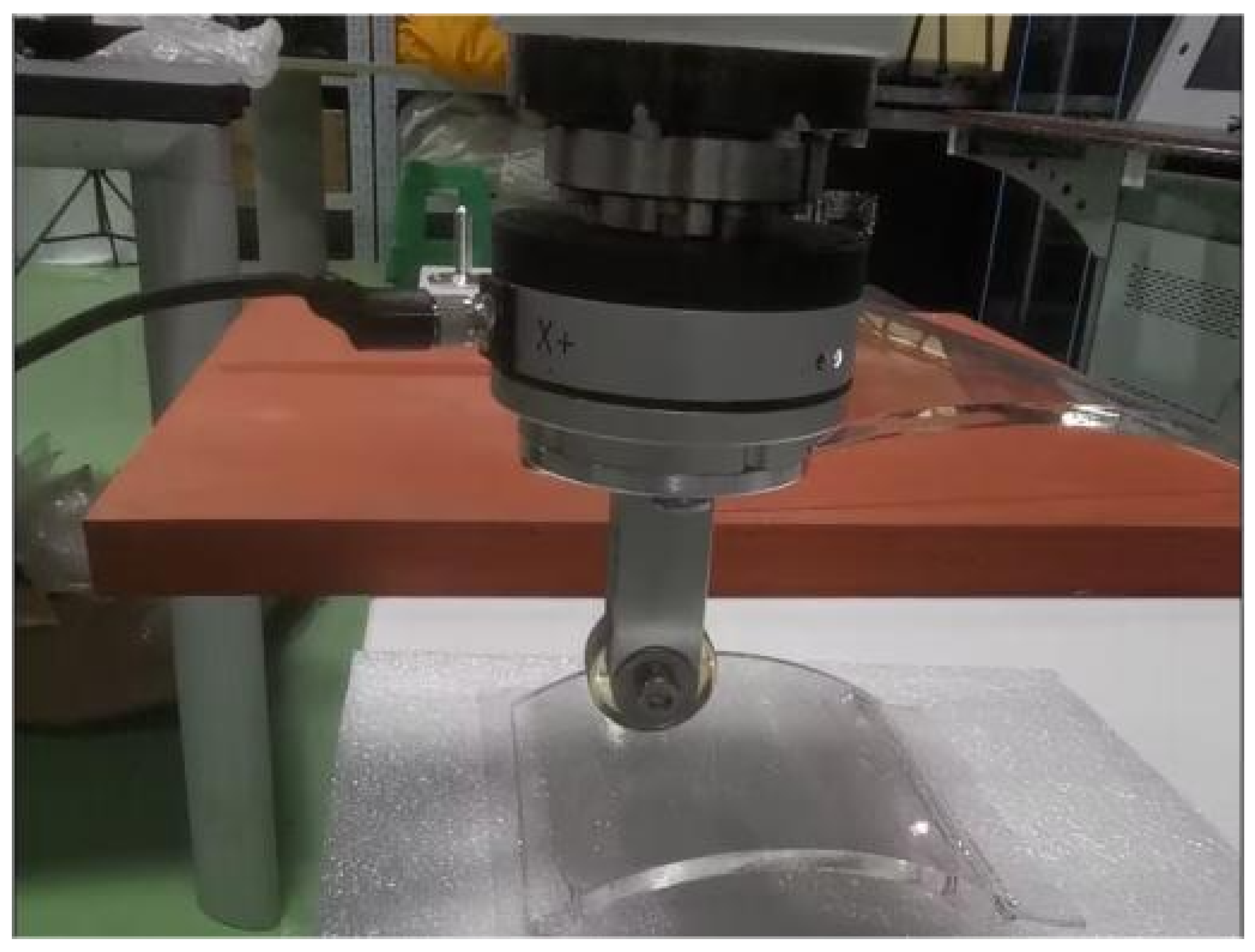
4.1. Construction of the Experiment Platform

The hardware environment of the platform was mainly composed of the following four components: host computer, force acquisition system, SD7-700 manipulator system, and motion control system.
The upper computer of the experiment equipped with Windows 10 and the system memory was 64 GB. The force acquisition system adopted the KWR75 series strain six-axis force sensor developed by Kunwei. The manipulator’s joint sensors and force sensor values communicated with the host computer through the EtherCAT bus communication protocol and carried out real-time control through Simulink Real-Time. The expected position signal transmitted by the host computer to the lower computer and the sensor signal transmitted by the lower computer to the host computer were used as the input and output of the control system. The motion controller adopted was KAGO-6301.
The experiment used the Simulink Real-Time module for real-time control. It was mainly needed to complete the path planning of the manipulator, inverse kinematics solution, data communication, and so on. The upper computer transmitted the position input instruction to the lower computer through the Ethercat PDO Transmit module of Simulink Real-Time through the Ethercat bus. At the same time, the sensors of each axis of the manipulator transmitted the sensor value to the host computer in real time through the Ethercat PDO Receive module to realize the effect of PID feedback control.

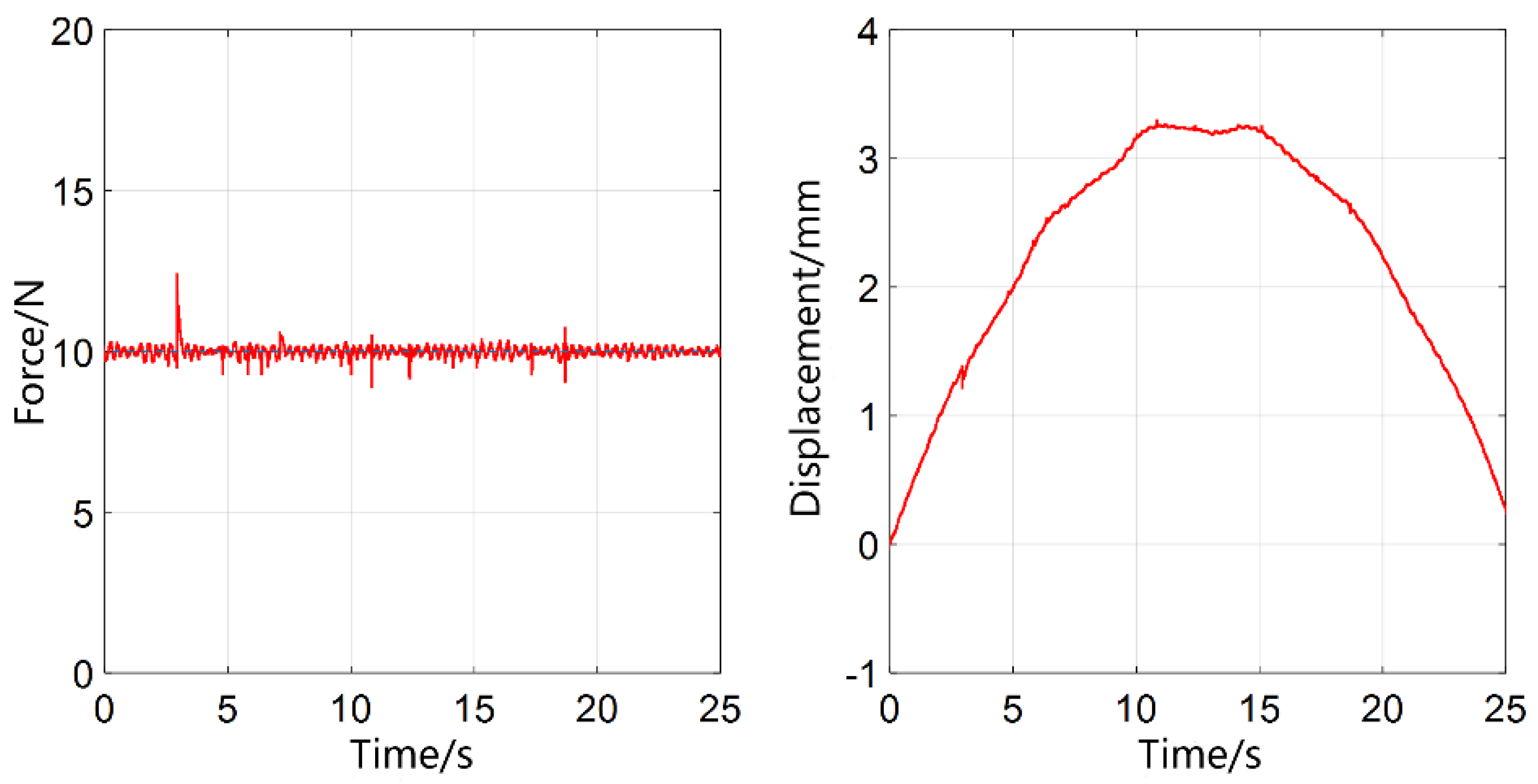
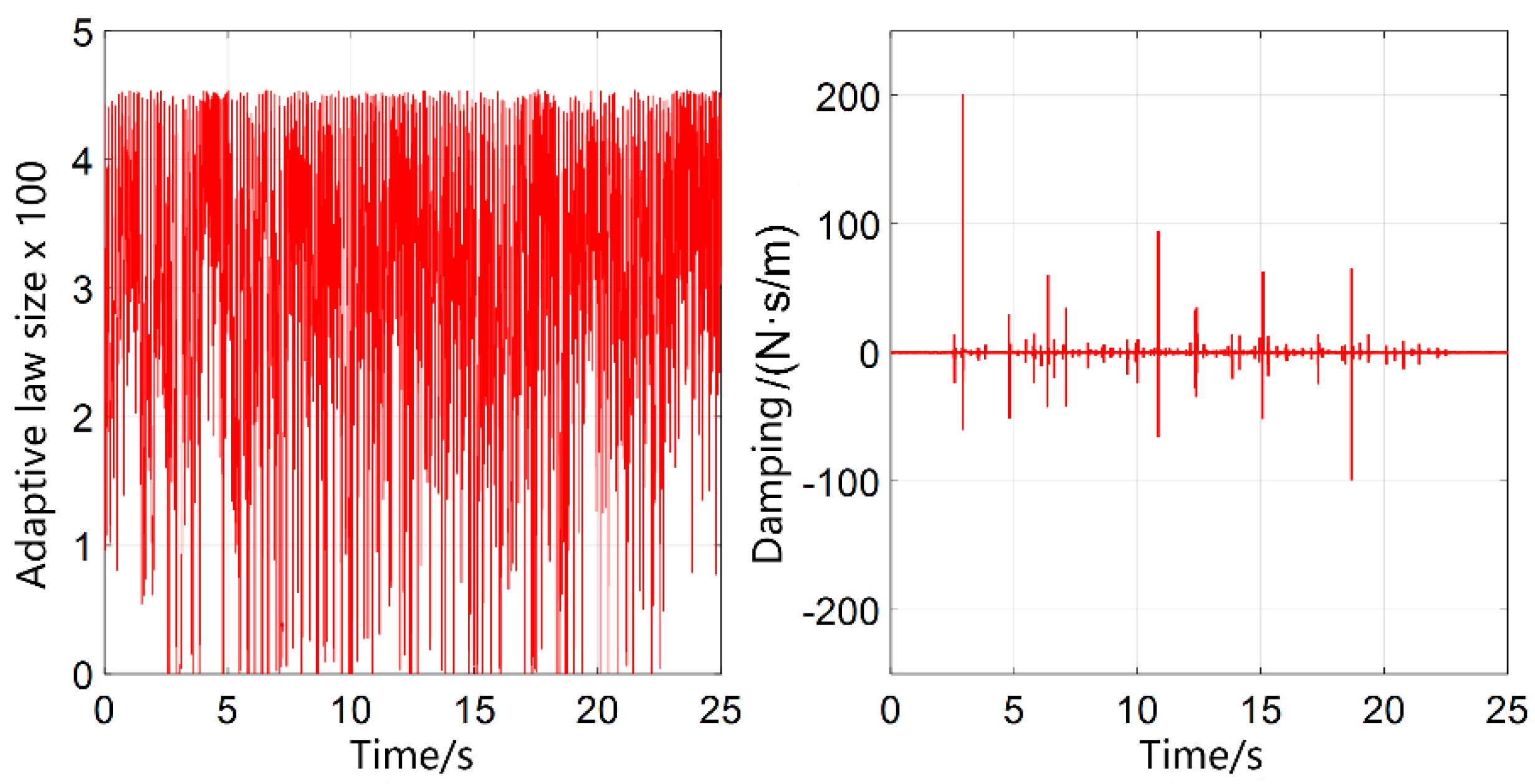
4.2. Experiment Design

As shown in Figure 4, the working surface of the manipulator was an acrylic glass surface, which was cushioned by a foam plate to avoid damage to the manipulator and the acrylic surface. After several debugging rounds, the impedance control parameters were selected: m = 1 , b = 200 , and k = 0 .
Applying the ordinary impedance control to the curved surface force-tracking experiment proceeded as follows. The manipulator was given a desired force of 10 mm/s, and the manipulator reached a stable state in the Z direction of the Cartesian space under the feedback of the force outer loop. The manipulator moved uniformly along the direction of Cartesian space at a speed of 1 mm/s. We observed the numerical changes collected by the force sensor in the uniform motion stage and the displacement changes of the end of the manipulator obtained by the joint position sensor after the forward kinematics of the manipulator. The sampling time was 2 ms.
The results are shown in Figure 5. From the experimental results, it can be seen that the ordinary impedance was controlled in the curved surface environment. The force tracking error was more prominent at the position with a more significant curvature. In the rising stage of the curved surface, the maximum contact force was 11.6 N. In the falling phase of the curved surface, the minimum contact force was 8.5 N, and the relative accuracy of the force control was more than 10%. The force tracking value was generally in a curve shape. In the rising stage, the slope decreased from large to small, and the force tracking error slipped from large to small. In the falling phase, the gradient increased from small to large, the contact force decreased, and the force-tracking error increased from small to large.
We kept the experimental environment unchanged and set the initial damping to B = 200 Nm/s. The adaptive variable-damping algorithm impedance control was used for the surface force-tracking experiment. The experimental results are shown in Figure 6 below.
Comparing Figure 6 with Figure 5, it can be observed that the surface force-tracking curve based on adaptive variable-damping impedance control exhibited overall fluctuations in the force-tracking error around the desired force of 10 N, which did not change with the trend of the surface slope variation. Apart from a significant fluctuation that reached 12.4 N, the force fluctuation remained stable within 1 N during the rest of the experimental process.
The corresponding adaptive law and damping variation in the surface force-tracking experiment based on adaptive variable damping are shown in Figure 7, indicating that the damping parameter and adaptive law of the manipulator adjusted accordingly when the curvature of the contact environment changed, aiming to regulate the control performance.
In the curved surface scenario, the manipulator moved along the x-axis at a speed of 1 mm/s. Experiments were conducted using the adaptive variable-damping algorithm and the conventional impedance algorithm, with desired forces set at 1 N, 5 N, 10 N, and 20 N. The control effectiveness was evaluated based on the maximum force error, and the performance comparison is presented in Table 1.
From the experimental results, it can be observed that the relative accuracy of force control of conventional impedance control in a curved surface environment was above 15%. In contrast, the force tracking curve based on adaptive variable-damping impedance control exhibited overall fluctuations near the desired force with a relative accuracy of force control of approximately 5% to 7%. The force fluctuations were stable within that range. In the research conducted by scholar Li Zhengyi on neural-network-based adaptive impedance control, where the robotic arm’s end-effector contacted a wooden board in the normal direction and a 2 N desired force was given, the maximum deviation of the contact force after stabilization was 0.2 N, with a relative accuracy of force control of 10% [28]. In comparison to our study, where the contact curvature varied significantly and the surface contact was more unknown, the overall relative accuracy of force control of the adaptive variable-damping impedance control algorithm remained below 10%. Based on the overall experimental results, it can be concluded that compared to conventional impedance control and other conventional adaptive impedance control methods, the force-tracking error curve of the impedance control based on the adaptive variable-damping algorithm is smoother, and it exhibits superior force-tracking performance in a curved-surface scenario.

5. Conclusions

This paper investigated the influence of impedance control model parameters on impedance control. Based on this, suitable inertia and stiffness parameters were selected, and an adaptive algorithm with variable damping was employed to adapt to unknown contact surface environments. The stability of the algorithm was proven, and a comparison was made between the input response and transient overshoot of the impedance control based on adaptive variable-damping and conventional impedance control. The selection criteria for the adaptive law were obtained. Finally, the effectiveness of the algorithm was demonstrated through real-time control experiments on the SD7-700 robotic arm system.
According to the experimental results, the force-tracking error of ordinary impedance control increased with the increase in surface curvature, and the maximum relative accuracy of force control was more than 15%, indicating poor force-tracking performance. In other literature studies, adaptive impedance control also generally has a maximum relative accuracy of force control of around 10%. In contrast, in this study, impedance control based on the adaptive variable-damping algorithm demonstrated a significant improvement in force-tracking performance. In an unknown environment, where the adaptive law varied with the motion of the robotic arm, the force-tracking error remained stable around the desired force and fluctuated less. The relative accuracy of force control was between 5% and 7%, leading to a notable enhancement in force-tracking effectiveness.
Based on the experimental results, it can be concluded that impedance control based on the adaptive variable-damping algorithm outperforms conventional impedance control in force-tracking performance in unknown contact-surface environments. It has positive implications for robot contact control applications. In the force-tracking experiment section, the construction of the surface for force-tracking experiments was relatively simple. In the future, experiments can be conducted on more complex surfaces or in environments with different surface materials to further evaluate the force-tracking performance of the adaptive variable-damping law in diverse and complex environments.

Author Contributions

Software, D.G.; Investigation, Y.S.; Writing-original draft, D.G. and Y.S.; Writing—review and editing, M.Z.; Funding acquisition, M.Z. and Y.T.; Visualization, J.J.; Project administration, S.Z. All authors have read and agreed to the published version of the manuscript.

Funding

This study was supported by the National Natural Science Foundation of China (grant no. 62303095), the Natural Science Foundation of Sichuan Province (2023NSFSC0872), and the Shenzhen Science and Technology Program under grant CYJ20210324143004012.

Data Availability Statement

The data presented in this study are available in this article.

Conflicts of Interest

The authors declare no conflict of interest.

References

  1. Nabat, V.; Rodriguez, M.d.O.; Company, O.; Krut, S.; Pierrot, F. Par4: Very high speed parallel robot for pick-and-place. In Proceedings of the 2005 IEEE International Conference on Intelligent Robots and Systems, Edmonton, AB, Canada, 2–6 August 2005; pp. 553–558. [Google Scholar]
  2. Yang, G.; Chen, I.M.; Yeo, S.H.; Lin, W. Design and analysis of a modular hybrid parallel-serial manipulator for robotised deburring applications. In Smart Devices and Machines for Advanced Manufacturing; Springer: Berlin/Heidelberg, Germany, 2008; pp. 167–188. [Google Scholar]
  3. Xu, P.; Li, B.; Chueng, C.F. Dynamic analysis of a linear Delta robot in hybrid polishing machine based on the principle of virtual work. In Proceedings of the 18th International Conference on Advanced Robotics, Hong Kong, China, 10–12 July 2017; pp. 379–384. [Google Scholar]
  4. Wu, J.; Gao, Y.; Zhang, B.; Wang, L. Workspace and dynamic performance evaluation of the parallel manipulators in a spray-painting equipment. Robot. Comput. Integr. Manuf. 2017, 44, 199–207. [Google Scholar] [CrossRef]
  5. Cherubini, A.; Navarro-Alarcon, D. Sensor-Based Control for Collaborative Robots: Fundamentals, Challenges, and Opportunities. Front. Neurorobot. 2021, 14, 113. [Google Scholar] [CrossRef]
  6. Li, T.; Huang, R.; Chen, L.; Jensen, C.S.; Pedersen, T.B. Compression of uncertain trajectories in road networks. Proc. VLDB Endow. 2020, 13, 1050–1063. [Google Scholar] [CrossRef]
  7. Li, T.; Chen, L.; Jensen, C.S.; Pedersen, T.B. TRACE: Real-time compression of streaming trajectories in road networks. Proc. VLDB Endow. 2021, 14, 1175–1187. [Google Scholar] [CrossRef]
  8. Li, T.; Chen, L.; Jensen, C.S.; Pedersen, T.B.; Gao, Y.; Hu, J. Evolutionary clustering of moving objects. In Proceedings of the 2022 IEEE 38th International Conference on Data Engineering (ICDE), Kuala Lumpur, Malaysia, 9–12 May 2022; pp. 2399–2411. [Google Scholar]
  9. Xu, K.; Wang, S.; Yue, B.; Wang, J.; Peng, H.; Liu, D.; Chen, Z.; Shi, M. Adaptive impedance control with variable target stiffness for wheel-legged robot on complex unknown terrain. Mechatronics 2020, 69, 102388. [Google Scholar] [CrossRef]
  10. Zhu, M.; Briot, S.; Chriette, A. Sensor-based design of a Delta parallel robot. Mechatronics 2022, 87, 102893. [Google Scholar] [CrossRef]
  11. Zhu, M.; Huang, C.; Qiu, Z.; Zheng, W.; Gong, D. Parallel Image-Based Visual Servoing/Force Control of a Collaborative Delta Robot. Front. Neurorobot. 2022, 16, 922704. [Google Scholar] [CrossRef]
  12. Prats, M.; Martinet, P.; del Pobil, A.P.; Lee, S. VIsion force control in task-oriented grasping and manipulation. In Proceedings of the 2007 IEEE/RSJ International Conference on Intelligent Robots and Systems, San Diego, CA, USA, 29 October–2 November 2007; pp. 1320–1325. [Google Scholar] [CrossRef]
  13. Raibert, M.H.; Craig, J.J. Hybrid position/force control of manipulators. J. Dyn. Syst. Meas. Control 1981, 102, 126–133. [Google Scholar] [CrossRef]
  14. Baeten, J.; Schutter, J.D. Integrated Visual Servoing and Force Control—The Task Frame Approach; Springer: New York, NY, USA, 2004. [Google Scholar]
  15. Li, H.; Wang, S.; Shi, H.; Su, C.; Li, P. Two-Dimensional Iterative Learning Robust Asynchronous Switching Predictive Control for Multiphase Batch Processes With Time-Varying Delays. IEEE Trans. Syst. Man Cybern. Syst. 2023, 53, 6488–6502. [Google Scholar] [CrossRef]
  16. Liu, Z.; Sun, Y. Adaptive variable impedance control with fuzzy-pi compound controller for robot trimming system. Arab. J. Sci. Eng. 2022, 47, 15727–15740. [Google Scholar] [CrossRef]
  17. Zhu, Y.; Qiao, J.; Lei, G. Adaptive Sliding Mode Disturbance Observer-Based Composite Control With Prescribed Performance of Space Manipulators for Target Capturing. IEEE Trans. Ind. Electron. 2018, 66, 1973–1983. [Google Scholar] [CrossRef]
  18. Wei, D.; Li, Z.; Wei, Q.; Su, H.; Song, B.; He, W.; Li, J. Human-in-the-loop control strategy of unilateral exoskeleton robots for gait rehabilitation. IEEE Trans. Cogn. Dev. Syst. 2019, 13, 57–66. [Google Scholar] [CrossRef]
  19. Wang, S.; Li, H.; Li, H.; Shi, H.; Sun, Q.; Li, P. Robust dynamic output feedback predictive control for discrete uncertain systems with time-varying delays. Trans. Inst. Meas. Control 2023. [Google Scholar] [CrossRef]
  20. He, W.; Dong, Y.; Sun, C. Adaptive Neural Impedance Control of a Robotic Manipulator With Input Saturation. IEEE Trans. Syst. Man Cybern. Syst. 2017, 46, 334–344. [Google Scholar] [CrossRef]
  21. Li, Y.; Li, T.; Gui, Y.; Gao, D.W.; Zhang, Y. Controllable Structure Planning for Energy Internet. In Proceedings of the 2022 First International Conference on Cyber-Energy Systems and Intelligent Energy (ICCSIE), Shenyang, China, 14–15 January 2023; pp. 1–6. [Google Scholar]
  22. Dai, X.; Song, S.; Xu, W.; Huang, Z.; Gong, D. Modal space neural network compensation control for Gough-Stewart robot with uncertain load. Neurocomputing 2021, 449, 245–257. [Google Scholar] [CrossRef]
  23. Li, Z.; Cao, H. Robot impedance control method adapting to unknown or changing environment stiffness and damping parameters. China Mech. Eng. 2014, 25, 1581. [Google Scholar]
  24. Deng, Y.; Léchappé, V.; Zhang, C.; Moulay, E.; Du, D.; Plestan, F.; Han, Q.L. Designing Discrete Predictor-Based Controllers for Networked Control Systems with Time-varying Delays: Application to A Visual Servo Inverted Pendulum System. IEEE/CAA J. Autom. Sin. 2022, 9, 1763–1777. [Google Scholar] [CrossRef]
  25. Zhu, M.; Huang, C.; Song, S.; Xu, S.; Gong, D. Vision-admittance-based adaptive RBFNN control with a SMC robust compensator for collaborative parallel robots. J. Frankl. Inst. 2023. [Google Scholar] [CrossRef]
  26. Jung, S.; Hsia, T.C.; Bonitz, R.G. Force tracking impedance control of robot manipulators under unknown environment. IEEE Trans. Control Syst. Technol. 2004, 12, 474–483. [Google Scholar] [CrossRef]
  27. Cao, H.; Chen, X.; He, Y.; Zhao, X. Dynamic adaptive hybrid impedance control for dynamic contact force tracking in uncertain environments. IEEE Access 2019, 7, 83162–83174. [Google Scholar] [CrossRef]
  28. Li, Z.; Cao, H. An impedance control method for robots that can adapt to unknown or varying environmental stiffness and damping parameters. J. Chin. Mech. Eng. 2014, 25, 5. [Google Scholar]
Figure 1. Impedance model of the mechanical arm.
Mathematics 11 04961 g001
Figure 2. Control algorithm of the impedance control.
Mathematics 11 04961 g002
Figure 3. Block diagram of the transfer function for impedance control.
Mathematics 11 04961 g003
Figure 4. Mechanical-arm surface force-tracking experiment.
Mathematics 11 04961 g004
Figure 5. Experimental results of surface force tracking.
Mathematics 11 04961 g005
Figure 6. Experimental results of surface force tracking based on adaptive variable damping (force tracking curve and the z-axis displacement curve of the manipulator end-effector).
Mathematics 11 04961 g006
Figure 7. Experimental results of surface force tracking based on adaptive variable damping (adaptive law change diagram and damping change diagram).
Mathematics 11 04961 g007
Table 1. Performance comparison of the adaptive variable-damping algorithm and conventional impedance algorithm in the curved-surface scenario.
AlgorithmMetricGiven the Desired Force
1 N5 N10 N20 N
Impedance controlMax force error/N0.320.841.633.73
Relative accuracy of force control32%16.8%16.3%18.65%
Adaptive variable damping controlMax force error/N0.070.270.551.18
Relative accuracy of force control7%5.4%5.5%5.9%
Disclaimer/Publisher’s Note: The statements, opinions and data contained in all publications are solely those of the individual author(s) and contributor(s) and not of MDPI and/or the editor(s). MDPI and/or the editor(s) disclaim responsibility for any injury to people or property resulting from any ideas, methods, instructions or products referred to in the content.

