Article

Stiffness Modeling and Dynamics Co-Modeling for Space Cable-Driven Linkage Continuous Manipulators

1
Shenzhen International Graduate School, Tsinghua University, Shenzhen 518055, China
2
Research Institute of Tsinghua University in Shenzhen, Shenzhen 518057, China
3
Mechanical Engineering, Harbin Institute of Technology, Harbin 150001, China
4
School of Aeronautics and Astronautics, Sun Yat-sen University, Shenzhen 518055, China
*
Author to whom correspondence should be addressed.
Mathematics 2023, 11(8), 1874; https://doi.org/10.3390/math11081874
Submission received: 9 March 2023 / Revised: 4 April 2023 / Accepted: 13 April 2023 / Published: 15 April 2023
(This article belongs to the Special Issue Mathematical Modeling in Nonlinear Control and Robotics)

Abstract

:
The space cable-driven continuous manipulator (SCCM) has a slender structure, ultra-high degrees of freedom, and a low mass, which make it suitable for equipment inspection and maintenance operations in an unstructured and limited space environment. In this paper, the SCCM including the cable network and plenty of joint links was deeply modeled. Firstly, the mapping relationship between the cable-driving space, joint space, and task space of the SCCM was studied, and the complete kinematic relationship of the SCCM was established. Secondly, the stiffness components of the SCCM are discussed, and the stiffness modeling method of each part is given. Finally, the Cartesian space equivalent stiffness model of the end was established. Then, a dynamic co-modeling method of Matlab + Adams is proposed, which greatly improved the modeling efficiency while ensuring the modeling accuracy. Finally, based on the stiffness model, the end stiffness characteristics of a specific configuration were analyzed, and the influence of the cable tension on the stiffness and frequency of the manipulator was analyzed. Based on the dynamic co-modeling, the task trajectory dynamics’ simulation analysis and space slit crossing experiment were carried out, which verified that the designed SCCM can meet the needs of slit crossing.

1. Introduction

The continuous manipulator is inspired by the structures of organisms, such as the elephant trunk, in nature [1]. The continuous manipulator is generally composed of elastic objects such as springs and flexible rods as the support skeleton [2,3,4,5] or a large number of modular links and joints in series [6]. Therefore, the continuous manipulator has ultra-high redundancy and even theoretically infinite degrees of freedom (DOFs). The cable-driven continuous manipulator (CCM) adopts a cable to transmit the driving force, which is convenient for the rear motor and the transmission part, reduces the volume and mass of the manipulator, and can give full play to the dexterity, dynamics, and flexibility of the continuous manipulator. It shows great application prospects in unstructured constrained environments. In a gravity-free environment, the cable-driven continuous manipulator’s advantages such as the long arm span, small diameter, and multiple DOFs can be highlighted, and it can carry out in-space inspection [7,8,9], on-orbit servicing [10], and spacecraft repair [11,12].
At present, scholars have proposed many kinds of CCMs, but the stiffness and load capacity of the CCM based on an elastic skeleton are weak. The rigid–flexible hybrid CCM with full-drive mode also faces the problem of low stiffness, and a large number of drive motors are needed to ensure dexterity. In view of this, Liu et al. [13,14,15] proposed a new hybrid active–passive cable-driven segmented continuous manipulator (APCSCM), as shown in Figure 1. A cable-constrained synchronous rotation mechanism (CCSRM) was designed to couple the same DOFs in each manipulator segment to achieve an approximate constant curvature, and the motion control of the segments is driven by three active cables. The APCSCM can have high stiffness and load capacity without sacrificing the dexterity and end accuracy. Liu et al. proposed an improved mechanism design of the new manipulator. Based on the structural characteristics, the kinematics equation of the active segment–joint angle was derived, and the kinematics, differential kinematics, and configuration planning were simplified. Peng et al. [12] applied the manipulator to the maintenance task of a space solar panel and proposed a synchronous planning method of the end pose and manipulator shape through the space slit based on the extended Jacobian matrix redundancy decomposition.
However, since the APCSCM with linkage cables is formed by a complex cable network, the complexity of the manipulator system is significantly increased. Liu et al. only discussed the structural design, kinematic model and motion planning of the APCSCM, and the stiffness modeling analysis of the APCSCM was lacking. Stiffness is very important for the study of the APCSCM, because it affects the motion accuracy, dynamic stability, and load-bearing capacity of the end. Wang et al. [16] proposed an eight-DOF variable stiffness CCM, derived the stiffness model of the manipulator from the Jacobin matrix, and used an optimization algorithm similar to the conjugate gradient method to calculate the stiffness. Oliver-Butler et al. [17] derived the analytical equation of the load deflection of the CCM by using the Bernoulli-Euler beam equation to analyze the influence of cable tension, skeleton compression, and cable position on the overall stiffness and pointed out that a non-parallel cable layout can significantly increase the stiffness of the CCM. Gu et al. [18] proposed a stiffness model and active stiffness control scheme of a two-DOF cable-driven redundant mechanism and verified the theory by simulation and experiment. Zhang et al. [19] proposed a CCM with a flexible skeleton, established the end stiffness model of the manipulator, and analyzed the factors affecting the end stiffness. Yuan et al. [20] proposed a stiffness modeling framework for a CCM composed of multiple series universal joints. The kinematic and static stiffness models of the manipulator were derived by analytical and numerical methods, and the two modeling methods were compared by simulation. Since the APCSCM contains a complex cable network composed of active driven cables and passive linkage cables, the stiffness model driven by the cable network is complex. At present, there is a lack of research on stiffness modeling and characteristic analysis of the related mechanisms.
The dynamic model is very important for the control and application of the CCM. Xu et al. [21] took the fully actuated CCM as the research object and established the dynamic equation considering the cable tension, friction force, and interaction force between adjacent links by the Newton–Euler iteration method. Ma et al. [22] established the dynamic model of the manipulator based on the work of [14] and divided the model into two parts: the links’ model and the cable network model. The multi-body dynamics of the links was established by the recursive method, and the driving cables were modeled as serial linear springs, while the linkage cables were modeled as individual linear torsion springs to reduce the difficulty of modeling. Zhou et al. [23] established a two-dimensional segmented manipulator system dynamics model considering cable friction and deformation by using the first kind of Lagrange equation and Baumgarte’s stability method. The arbitrary Lagrangian–Eulerian method was used to model the driving cable, and the LuGre model was used to describe the friction between the cable and manipulator. Li et al. [24] studied the statics and dynamics of the CCSRM in detail and proposed a CCSRM model considering cable friction and elastic deformation. The improved LuGre friction model was used to solve the linear contact friction of the cable pulley, and the dynamic model of the CCSRM was established. However, the APCSCM is long and has a large number of joints. Using multi-body dynamics methods such as the Newton–Euler method, the Lagrange method, the Kane equation [25], and the recursive method [26] to establish multi-joint link system dynamics has low computational efficiency and a high time complexity. In addition, there are a large number of elastic cables and through-hole frictions in the system. Establishing an accurate model of the cable based on the finite-element method requires much data space and calculation work. The establishment of the overall dynamic model of the manipulator is complicated; the calculation workload is large; the modeling efficiency is low.
In addition, the current research results are mainly for CCMs for ground applications. Different from the ground manipulator, the SCCM applied in the space microgravity environment has a longer arm span, and in order to improve the flexibility of motion, a multi-segment design is adopted with more DOFs. The mechanical model of this cable-driven multi-segment slender manipulator is extremely complex; the dynamic coupling is serious; the elastic vibration is more obvious; these bring great challenges to the modeling and control of such manipulators. In addition, the current research on the modeling and control of CCMs mainly focuses on relatively simplified situations, such as a single-segment manipulator or only plane motion, and most of the research focuses on the kinematics and configuration planning. For the stiffness, dynamics, and control of CCMs, especially considering the weightless environment, multiple segments, and the long manipulator, systematic and in-depth research results have not been obtained, and the relevant theories and methods still need to be improved.
The scientific contributions of this work are summarized as follows. This paper studies the space application of the APCSCM and gives the stiffness modeling method of the manipulator with an active–passive cable network and the simplified dynamic modeling scheme based on Matlab + Adams co-modeling. Specifically, first, the source of the stiffness of the SCCM was studied, that is the equivalent stiffness generated by the linkage cable and the driving cable. Finally, the Cartesian space equivalent stiffness model of the end was established. Based on this model, the end stiffness characteristics under specific configuration were analyzed. Second, the dynamic modeling and simulation analysis of the SCCM were carried out. The system was divided into the cable network model and the link model. The cable network model was established in Matlab, and the rigid link model was established in the Adams dynamic software. The system model established by Matlab + Adams can not only ensure the accuracy of the modeling, but also greatly improve the efficiency of the modeling. Finally, the dynamic simulation analysis was carried out by using the dynamic model of the SCCM, and the slit crossing experiment was completed.
The rest of this paper is organized as follows. In Section 2, the kinematic mapping relationship between the driving space, joint space, and task space is established. In Section 3, the equivalent stiffness model of the linkage cable and the driving cable is analyzed, and the equivalent stiffness of the Cartesian space at the end of the manipulator is derived. Section 4 gives the dynamic model of the cable part and the co-modeling method of Matlab + Adams of the manipulator system. In Section 5, the simulation experiment is carried out to analyze the influence of the cable tension on the end Cartesian space stiffness and the manipulator frequency. The dynamic simulation analysis of the manipulator and the slit crossing experiment are carried out to verify the correctness of the co-modeling method. The last section summarizes the whole paper and gives the conclusions.
The hypotheses of this paper were as follows:
(1)
The cable was equivalently simplified as a spring model, ignoring the mass and damping effects;
(2)
We ignored the hysteresis phenomenon in the movement of the manipulator;
(3)
Only the friction between the cable and the perforated disc was considered, and other frictions were ignored.

2. Kinematics Model

In this section, first of all, we introduce the research object. Then, the kinematics model of the single cross-axis joint angle to the cable length, the manipulator joint angle to the cable length, and the joint space to the end task space is established for the mechanism, which lays the foundation for the subsequent stiffness modeling.

2.1. Description of the SCCM

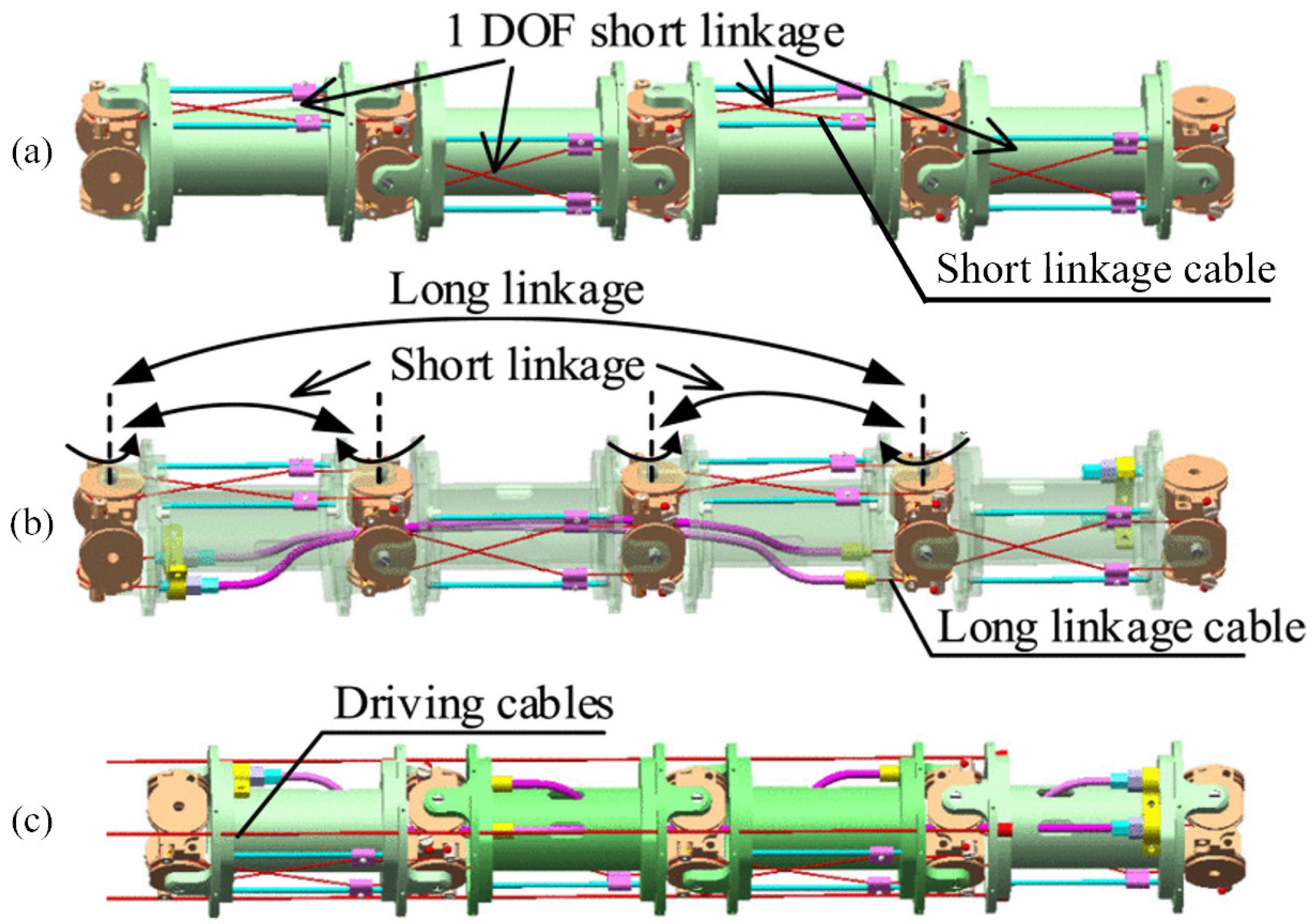
In this paper, the APCSCM was used as the research object of the SCCM. The manipulator configuration adopted the hybrid active–passive drive form of the discrete rigid link + synchronous rotation mechanism + cable. Specifically, the SCCM was composed of S manipulator segments. The s t h segment was composed of n s ( s = 1 , , S ) links and cross-axis joints in series, and the DOFs in the same direction in each segment were coupled together by linkage cables, while the motion was controlled by 3 outer driving cables. As shown in Figure 2, the adjacent cross-axis joints in the segment were coupled by the short linkage cables and the long linkage cables to ensure that the rotation angles between the sub-joints in the segment were approximately equal, and the equal curvature bending of the segment was realized. This configuration can reduce the number of drive motors and effectively improve the stiffness and end positioning accuracy of the manipulator.

2.2. Single Cross-Axis Joint Angle to Cable Length

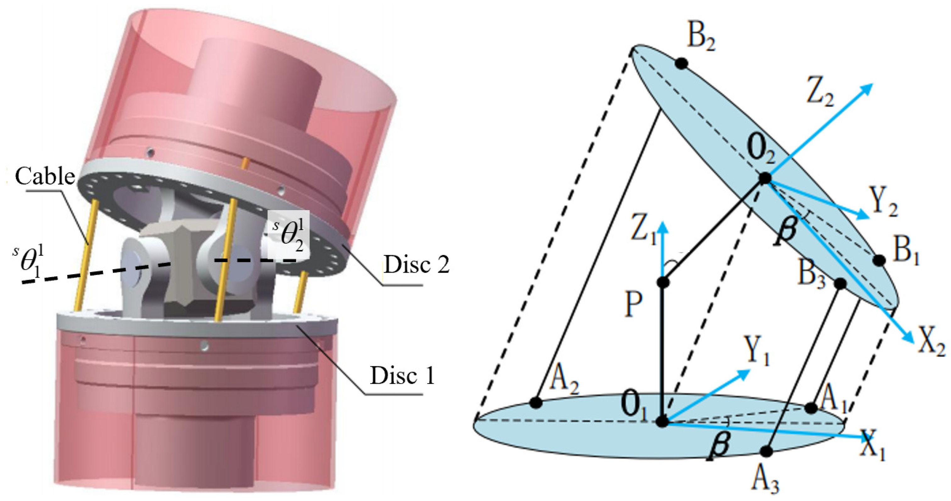
According to the structural design of the manipulator, only the cable length at the cross-axis joint will change during the movement. In order to establish the mapping relationship between the cable length and joint angle, it was necessary to establish the relationship between the single cross-axis joint angle and cable length. The first cross-axis joint and the first group of driving cables in the s-segment were modeled as examples. As shown in Figure 3, P represents the center of the cross-axis joint. O 1 and O 2 represent the center of two disk surfaces before and after the joint, respectively. The definition of the single joint coordinate system is shown in Figure 3.
The length of the cable between the two discs before and after the cross-axis is expressed by the corresponding two joint angles. Taking the first cable in the first group of cables as an example, the length expression formula is as follows:
a 1 b 1 = d s s θ 1 1 + r c s θ 1 1 c s β 1 r c s β 1 r c s β 1 s s θ 1 1 s s θ 2 1 + r c s θ 2 1 s s β 1 d c s θ 1 1 s s θ 2 1 r s s β 1 r s s θ 2 1 s s β 1 r c s β 1 c s θ 2 1 s s θ 1 1 + d c s θ 1 1 c s θ 2 1 + d 0 = a 1 2 + b 1 2 + c 1 2 1 2 ,
a 1 = d s s θ 1 1 + r c s θ 1 1 c s β 1 r c s β 1 b 1 = r c s β 1 s s θ 1 1 s θ 2 + r c s θ 2 1 s s β 1 d c s θ 1 1 s s θ 2 1 r s s β 1 c 1 = r s s θ 2 1 s s β 1 r c s β 1 c s θ 2 1 s s θ 1 1 + d c s θ 1 1 c s θ 2 1 + d
where d represents the distance between two discs, r is the distance from the center of cable hole to the center of the disc, and s β 1 is the distribution angle of the cable on the disc. s θ 1 1 and s θ 2 1 represent the rotation angles of the two rotation axes of the first cross-axis of the s-segment, respectively.
The calculation formula of the other cable lengths in the first group of cables is the same as Equation (1), and s β 1 needs to be changed according to the cable distribution angle. Since there were three cables in each group, that is w s = 3 ( w s represents the number of motors and driving cables in the s-segment), they were evenly distributed on the disc at an interval of 120 . s β 1 was replaced by s β 1 + 2 π / 3 and s β 1 + 4 π / 3 , respectively, when calculating the length of other two cables. By differentiating Equation (1), the velocity-level kinematic equations of single-joint drive space and joint space can be obtained:
s l ˙ i j = s g i j s θ ˙ j i = 1 , 2 , , s ; j = 1 , 2 , , n s
where s l i j is the length of the i-group cables corresponding to the j-cross-axis joint in the s-segment, s θ j is the rotation angle corresponding to the j-cross-axis joint in the s-segment, and s θ j = s θ 1 j s θ 2 j T . s g i j R w s × 2 is the mapping matrix between the joint angular velocity s θ ˙ j and the cable length velocity s l ˙ i j . The specific expression is as follows:
s g i j = a 1 b 1 1 2 a 1 a 1 s θ 1 j + b 1 b 1 s θ 1 j + c 1 c 1 s θ 1 j a 1 b 1 1 2 a 1 a 1 s θ 2 j + b 1 b 1 s θ 2 j + c 1 c 1 s θ 2 j a w s b w s 1 2 a w s a w s s θ 1 j + b w s b w s s θ 1 j + c w s c w s s θ 1 j a w s b w s 1 2 a w s a w s s θ 2 j + b w s b w s s θ 2 j + c w s c w s s θ 2 j .

2.3. Manipulator Joint Angle to Cable Length

In the previous subsection, we established the kinematics equation of a single joint. The velocity-level relationship between the joint angle of the s-segment and cable length is as follows:
s l ˙ = s G θ s θ ˙ ,
s G θ = s g 1 1 s g 1 2 s g 1 n s s g 2 1 s g 2 2 s g 2 n s s g s 1 s g s 2 s g s n s R W s × 2 n s
where s G θ denotes the mapping matrix from the joint angular velocity to the variation of all cable lengths of the s-segment. W s represents the number of all driving cables and corresponding motors passing through the s-segment, and s θ represents the matrix of the joint variables of all joints in the s-segment, s θ = s θ 1 s θ 2 s θ n s T R 2 n s × 1 .
After obtaining the kinematic relationship of all manipulator segments, we can assemble the kinematic relationship between the joint space and the driving space of the entire manipulator:
L ˙ = G θ Θ ˙ ,
G θ = 1 G θ 0 0 0 1 G θ 2 G θ 0 0 1 G θ 2 G θ S 1 G θ 0 1 G θ 2 G θ S 1 G θ S G θ R W × 2 N
where G θ is the Jacobian matrix from the joint space to the driving space. W represents the total number of system motors and driving cables, W = s = 1 S w s . N represents the total number of system links and cross-axis joints, N = s = 1 S n s . Θ represents the vector composed of joint angles of all segments of the manipulator, Θ = 1 θ 2 θ S θ T R 2 N × 1 .

2.4. Joint Space to Task Space

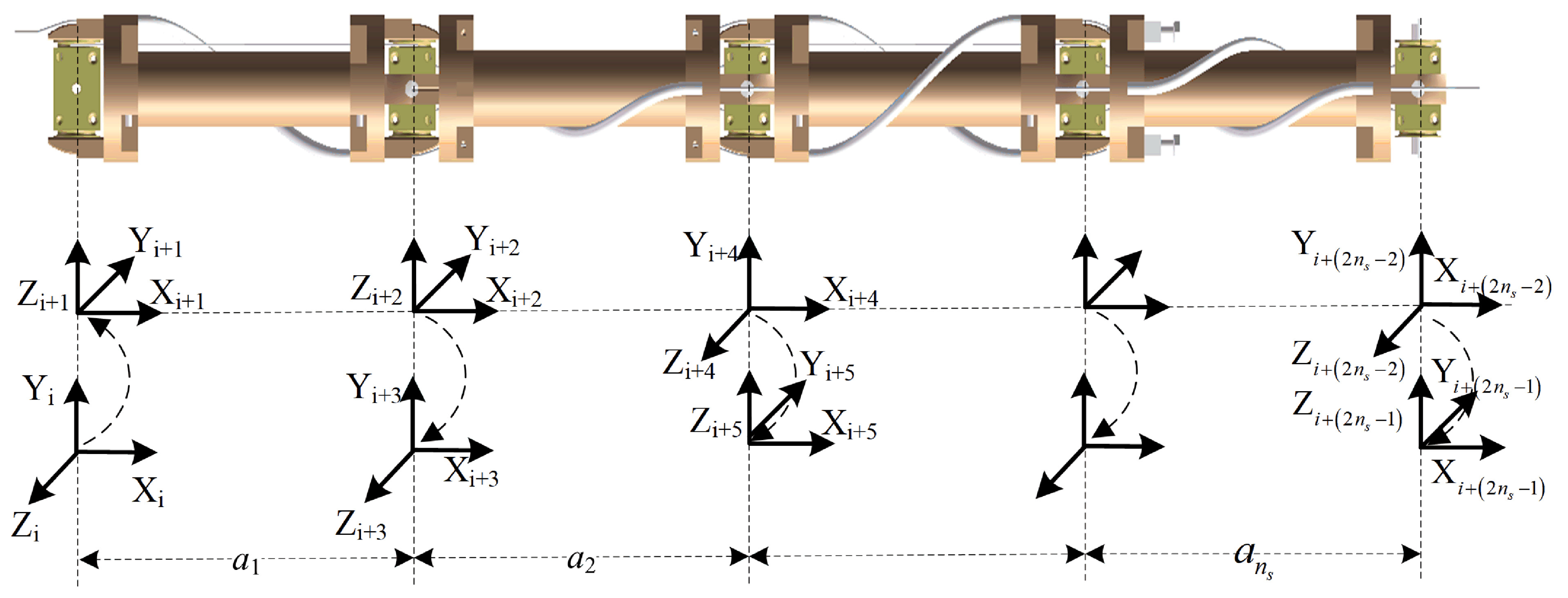
In order to obtain the kinematics relationship between the joint space and the task space, the D-H coordinate system shown in Figure 4 was established for the s-segment. Then, the s-segment position-level kinematic relationship can be obtained by the homogeneous transformation matrix multiplication:
T s = 1 T s , 2 2 T s , 3 2 n s 3 T s , 2 n s 2 2 n s 2 T s , 2 n s 1
where i T s , i + 1 is the homogeneous transformation matrix of the adjacent D-H coordinate system in the s-segment, which can be written as
i T i + 1 = c s θ i j c s α i s s θ i j s s α i s s θ i j s a i c s θ i j s s θ i j c s α i c s θ i j s s α i c s θ i j s a i s s θ i j 0 s s α i c s α i s d i 0 0 0 1 .
The specific values of the D-H parameters are shown in Table 1. The kinematic equation of the overall position-level of the manipulator can be obtained by the homogeneous matrix multiplication of all segments:
T e = Π s = 1 S T s .
The velocity-level kinematics relationship between the joint of the manipulator and the end pose is
P ˙ e = J θ Θ ˙
where J θ = T e T e Θ Θ R 6 × 2 N is the Jacobian matrix from the joint space to the end Cartesian space.

3. Stiffness Model

In this section, based on the kinematics model, the equivalent stiffness of the linkage cable and the driving cable is modeled, respectively, and then, the stiffness of the two cables is combined to establish a complete manipulator stiffness model.

3.1. Equivalent Stiffness Modeling of Linkage Cable

The length of a short linkage cable between two adjacent joints is l c 1 ; the cross-sectional area is A c 1 ; Young’s modulus is E c 1 . The length of a long linkage cable is l c 2 ; the cross-sectional area is A c 2 ; Young’s modulus is E c 2 . The joint rotation radius of the short linkage cable is r θ , and the radius of the long linkage cable is r φ .
When there is a non-zero relative rotation angle between two adjacent joints, the difference between the strains of the two short linkage cables between the two adjacent joints is
Δ ε = 2 r θ Δ θ / l c 1 .
The inconsistency of these two cable strains will produce a non-zero resultant moment on the corresponding joint:
Δ Z = r θ E c 1 A c 1 Δ ε .
From Equations (11) and (12), the equivalent stiffness of the two short linkage cables between the adjacent joints at the corresponding joints can be obtained as follows:
k θ c 1 = 2 E c 1 A c 1 r θ 2 / l c 1 = 2 k c 1 r θ 2 .
Similarly, the equivalent stiffness of the two long linkage cables between the two adjacent joints at the corresponding joints is
k φ c 2 = 2 E c 2 A c 2 r φ 2 / l c 2 = 2 k c 2 r φ 2 .
k c 1 and k c 2 represent the tensile stiffness of the short linkage and long linkage cables, respectively. For any s-segment of the manipulator, the joint equivalent stiffness matrix corresponding to the linkage cables is
s K θ c = s K θ 1 0 0 0 0 0 0 s K θ 2 0 0 0 0 0 0 s K θ 3 0 0 0 0 0 0 s K θ 4 0 0 0 0 0 0 0 0 s K θ 3 0 0 0 0 0 0 s K θ 4 0 0 0 0 0 0 0 0 0 0 0 0 0 0 0 0 0 0 0 0 0 0 s K θ 3 0 0 0 0 0 0 s K θ 4 0 0 0 0 0 0 s K θ 2 0 0 0 0 0 0 s K θ 1 R 2 n s × 2 n s
where s K θ 1 = k θ c 1 0 0 k θ c 1 0 0 , s K θ 2 = 0 k φ c 2 k φ c 2 0 0 0 , s K θ 3 = 0 k φ c 2 k θ c 1 + k φ c 2 0 0 k θ c 1 , and s K θ 4 = k θ c 1 0 0 k θ c 1 + k φ c 2 k φ c 2 0 .
The overall joint equivalent stiffness K θ c of the manipulator generated by the linkage cables is
K θ c = 1 K θ c 2 K θ c S K θ c R 2 N × 2 N
where 1 K θ c , 2 K θ c , ⋯, S K θ c represents the joint equivalent stiffness matrix corresponding to the linkage cable of the 1st, 2nd, …, and S t h segments of the manipulator, respectively.

3.2. Equivalent Stiffness Modeling of Driving Cable

According to the principle of virtual work, the work performed by the cable tension is equal to the work performed by the joint torque, that is
L ˙ T F l = Θ ˙ T τ d .
where F l R W × 1 represents the cable tension and τ d R 2 N × 1 is the joint torque. According to Equations (6) and (17), we can obtain
τ d = G θ T F l .
According to the variational principle, the variation on both sides of Equation (18) can be obtained:
δ τ d = δ G θ T F l + G θ T δ F l .
Similarly, for the driving cable, we have
δ F l = K l δ L ,  
K l = k 1 k 2 k W R W × W
where K l is the matrix composed of the tensile stiffness of the driving cable and k y y = 1 , 2 , , W is the tensile stiffness of the y t h cable.
According to the variational principle, when the joint torque of the manipulator changes slightly δ τ , the joint produces a group of corresponding small movements δ Θ , and the joint equivalent stiffness K θ d generated by the driving cables is
K θ d = δ τ δ Θ = H F l + G θ T K l δ L δ Θ = H F l + G θ T K l G θ
where H = δ G θ T δ Θ R W × 2 N × W is the partial derivative of the force Jacobian matrix from the joint space to the driving space relative to the joint variable, which is defined as a three-dimensional Hessian matrix.
The joint equivalent stiffness of the whole manipulator is generated by the linkage cable and driving cable. Therefore, the joint equivalent stiffness K θ of the manipulator is calculated by the following formula:
K θ = K θ d + K θ c = H F l + G θ T K l G θ + K θ c .
The joint equivalent stiffness given in Equation (22) consists of two parts. The first part H F l is related to the driving cable tension F l , which is called the joint active stiffness. The second part ( G θ T K l G θ + K θ c ) is related to the tensile stiffness of the driving cables and linkage cables, which is called the joint passive stiffness.

3.3. The Cartesian Space Equivalent Stiffness of the End

According to the principle of virtual work, the work performed by the joint torque is equal to the work performed by the external force at the end, that is
Θ ˙ T τ = P ˙ e T F e .
where F e R 6 × 1 is the external force at the end of the manipulator. According to Equations (10) and (23), we can obtain
τ = J θ T F e .
According to Equation (24), there can be F e = J θ T τ , and the variation on both sides is obtained:
δ F e = δ J q T τ + J q T δ τ .
According to the variational principle, when the force at the end of the manipulator changes slightly δ F e , it generates a set of corresponding micro-motions δ P e at the end. Then, the equivalent stiffness K θ of the joint is equivalent to the stiffness K e R 6 × 6 in the Cartesian space of the end:
K e = δ F e δ P e = δ J θ T δ P e τ + J θ T K θ δ Θ δ P e = J θ T K θ J θ 1 .
According to Equations (22) and (26), we can obtain
K e = J θ T H F l + G θ T K l G θ + K θ c J θ 1 = J θ T H F l J θ 1 + J θ T G θ T K l G θ + K θ c J θ 1 .
Similar to the joint space equivalent stiffness, the Cartesian space equivalent stiffness at the end of the manipulator is also composed of two parts. The first part J θ T H F l J θ 1 is related to the driving cable tension F l , which is called the end active stiffness. The second part J θ T G θ T K l G θ + K θ c J θ 1 is related to the tensile stiffness of the driving cables and the linkage cables, which is called the end passive stiffness.

4. Dynamics Modeling and Simulation

In this section, the modeling methods of the rigid manipulator and cable are given, respectively, and then, a co-modeling architecture is proposed, which lays the foundation for the simulation analysis in the next section.

4.1. Dynamics Equation

Because the mass of the driving cable and the linkage cable is very small, the influence of the cable mass characteristics on the dynamics can be ignored. Therefore, the overall dynamics equation of the SCCM can be expressed as follows:
M ( Θ ) Θ ¨ + c ( Θ , Θ ˙ ) Θ ˙ = τ c + τ d .
In the above equation, M is only related to the quality characteristic parameters, geometric parameters, and joint angle of the link. c is the Coriolis force and centripetal force term, which is related to the quality characteristic parameters, geometric parameters, joint angle, and angular velocity. τ d is the equivalent joint torque generated by the driving cable, as shown in Equation (18). τ c is the equivalent joint torque generated by the linkage cable, and its calculation formula is as follows:
τ c = K θ c Δ Θ C θ c Δ Θ ˙ .
where C θ c R 2 N × 2 N is the matrix composed of the damping coefficient of the linkage cable and Δ Θ R 2 N × 1 is the vector composed of the angle difference of the adjacent rotating joints.
When the friction between the cable and the perforated disc cannot be ignored, the friction model shown in Figure 5 can be used for modeling. The size relationship of F i 1 , f r o n t j , F i 1 , b a c k j is
F i 1 , b a c k j = F i 1 , f r o n t j e κ μ η i 1
where κ represents the direction of the friction force, which is 1 or −1, depending on the direction of the cable movement. μ depends on the material properties, and the test calibration μ = 0.309 . η is the relative angle between the two ends of the cable direction.
The expression of the tension F i of the i-th driving cable is
F i = k i Δ l i
where Δ l i is the total deformation of the i t h driving cable. Its calculation expression is
Δ l i = l i Θ l i 0 l i m .
where l i Θ is the length of the i t h driving cable at the current moment, l i 0 is the length at the initial moment, and l i m is the length driven by the motor, which is calculated by the motor motion.

4.2. Dynamics Co-Modeling Method

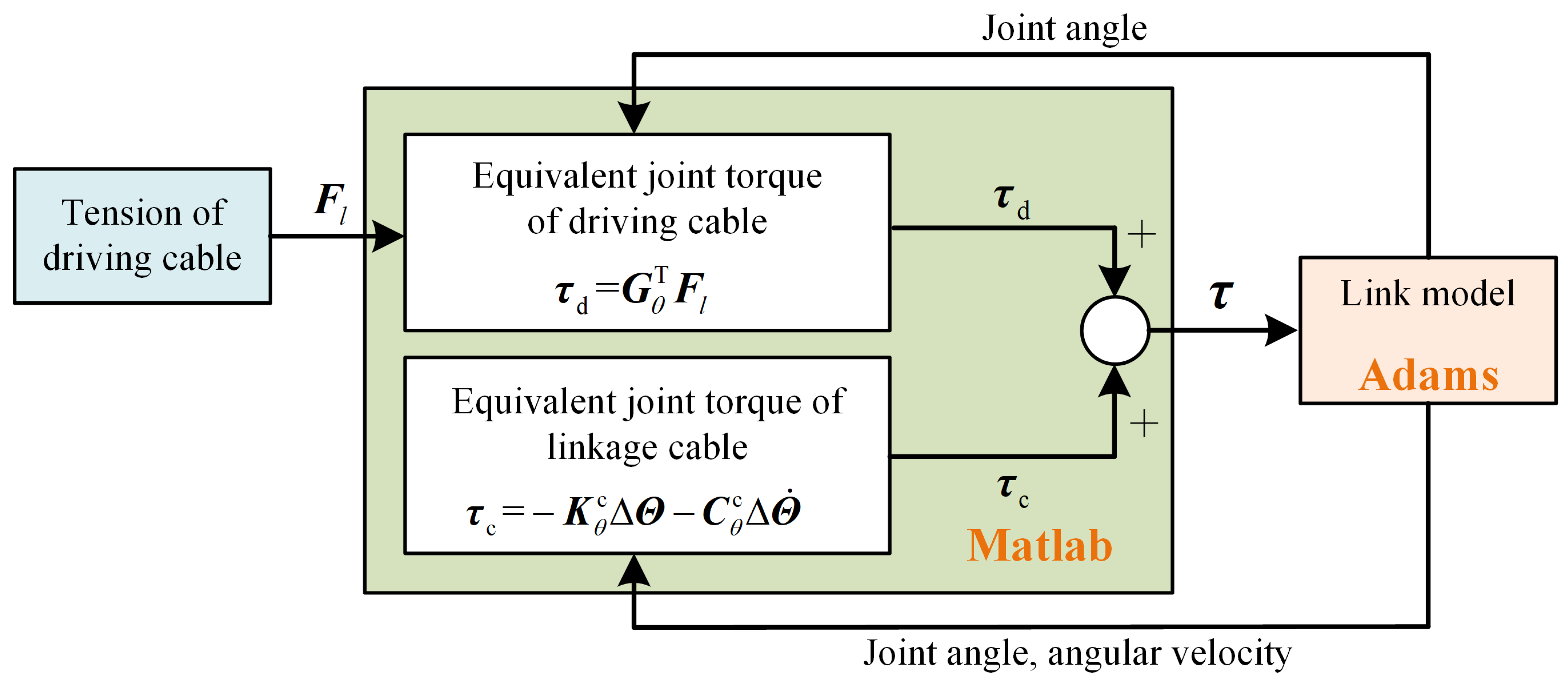
In order to reduce the workload of the dynamic development and facilitate the expansion to any multi-manipulator dynamic system (including a multi-flexible manipulator system or a multi-rigid and flexible manipulator hybrid system), this paper proposes a co-modeling method for cable-driven space manipulators. The key is to use the characteristics of the cable and link model being able to be modeled independently in the dynamic equation given in Equation (28). The cable model can be equivalent to the joint driving torque of the link model. At the same time, considering that the Adams and other dynamic commercial software cannot deal with the cable dynamics problem with a large amount of friction, we propose a co-modeling method of the cable-driven space manipulator based on Matlab + Adams. In Matlab, we established the cable dynamics model in the form of an algorithm (including the driving cable and linkage cable) and the link model in the Adams commercial software, as shown in Figure 6.

5. Simulation Analysis

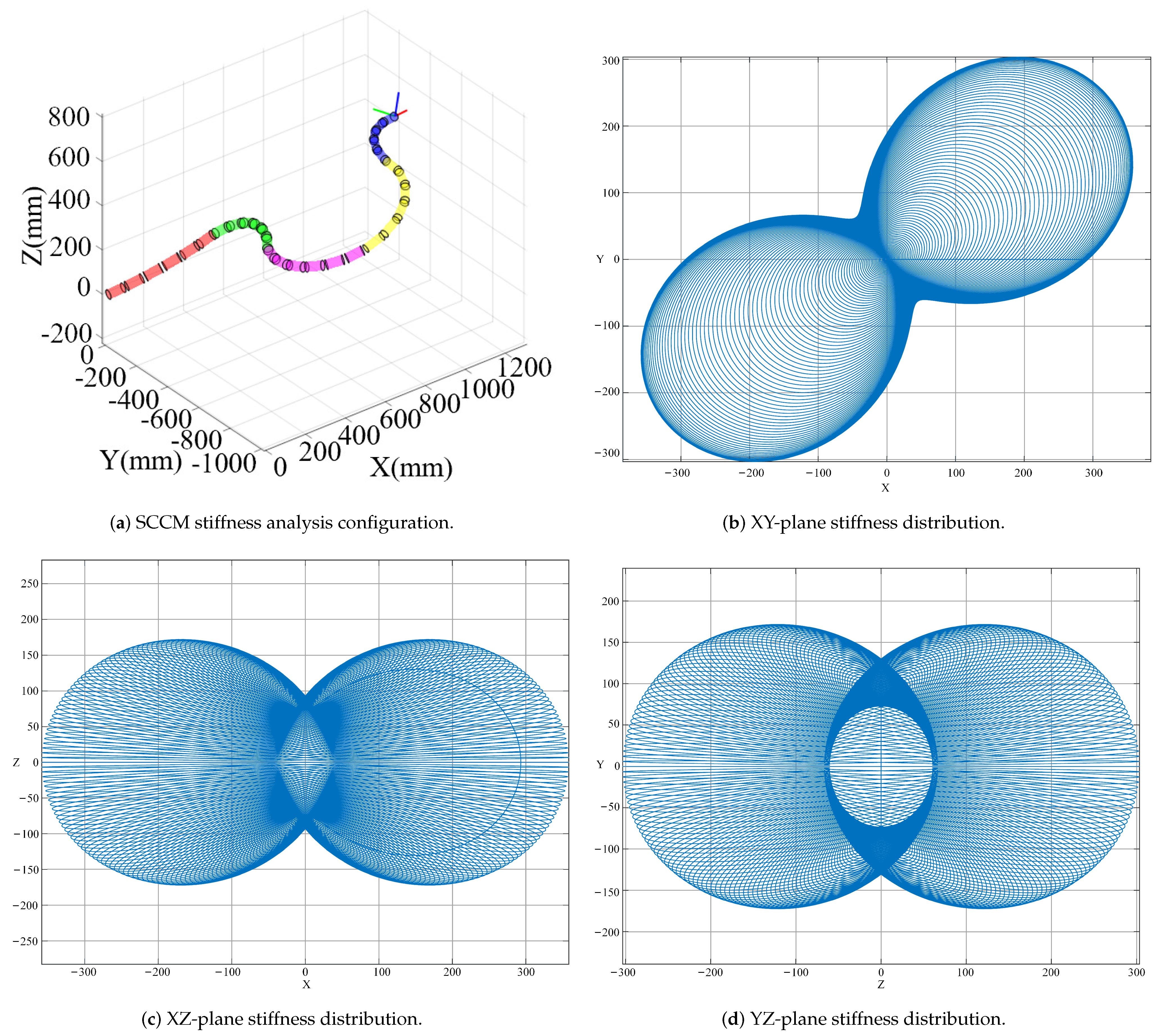
The configuration of the SCCM used for the simulation example is shown in Figure 7. It included five manipulator segments, each segment containing six links, and the adjacent links were connected by cross-axis joints. The six links achieved synchronous rotation in two orthogonal directions through the linkage cables, and each segment was driven by three driving cables. Therefore, the manipulator configuration contained a total of 15 driving cables. The parameters of linkage cable were as follows: The elastic modulus was E = 2.06 e 11 Pa, and the cross-sectional area of the cable was A = 5.03 e 7 m 2 . The length of short linkage cable was l c 1 = 0.085 m, and the joint rotation radius was r θ = 6.5 mm. The length of long linkage cable was l c 2 = 0.1 m, and joint rotation radius was r φ = 12.3 mm. The parameters of driving cable were as follows: the elastic modulus was E = 2.06 e 11 Pa, and the cross-sectional area was A = 1.13 e 6 m 2 .
The first three segments of the manipulator, a total of 18 links, used the same specification of the link structure. The latter two segments, a total of 12 links, used another specification of the link. The detailed parameters of the two link structures are shown in Table 2.

5.1. End Cartesian Space Stiffness

The joint angles of the manipulator in Figure 7 are as follows:
Θ = 6.5 7.8 13.5 2.0 15.0 9.6 15 8.0 12.2 0.7 r a d .
The ten joint angles in Equation (33) are composed of two DOFs in five segments. The rotation angle of the cross-axis joint in each segment is the value in Equation (33) divided by six (synchronous rotation design so that the rotation angle of each cross-axis is the same). The driving cable tension for the stiffness calculation is given as follows:
F l = 3 3 3 3 3 3 3 3 3 4 4 4 5 5 5 × 1 0 2 N .
According to the above content, the Cartesian space equivalent stiffness of the end is calculated:
K e = 304.3 110.5 0 25.1 0 39.3 110.5 257.7 0 60.3 0 0 0 0 145.7 0 53.2 19.7 25.1 60.3 0 17.8 0 0 0 0 53.2 0 44.1 9.7 39.3 0 19.7 0 9.7 62.2 N m / r a d .
Figure 7b to Figure 7d are the end Cartesian space stiffness distribution figures obtained by using Matlab to simulate the manipulator model shown in Figure 7a, which are the stiffness distributions of the end Cartesian space projected onto the XY, XZ, and YZ planes, respectively.

5.2. The Influence of Cable Tension on the End Cartesian Space Stiffness

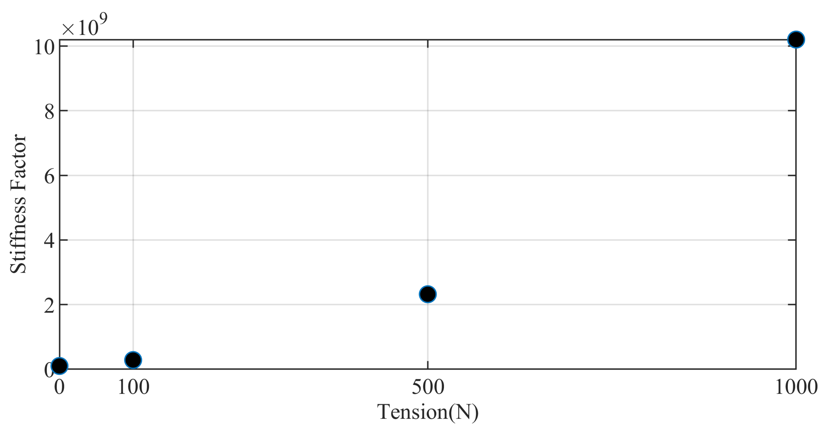
Firstly, the eigenvalue product σ = Π i = 1 6 σ i of the stiffness matrix K e is defined as the stiffness factor, that is σ is called the end Cartesian stiffness factor. The variation of the stiffness factor with the tension of the driving cable is shown in Figure 8, and the ratio of the stiffness factor under different tensions is shown in Table 3. It can be seen from the table that the stiffness factor of 100 N was more than 1.8-times higher than that of 0 N, the stiffness factor of 500 N was more than 22-times higher than that of 0 N, and the stiffness factor of 1000 N was more than 100-times higher than that of 0 N.

5.3. The Influence of Cable Tension on Manipulator Frequency

The system frequency calculation formula is as follows:
f = 1 2 π K θ M .
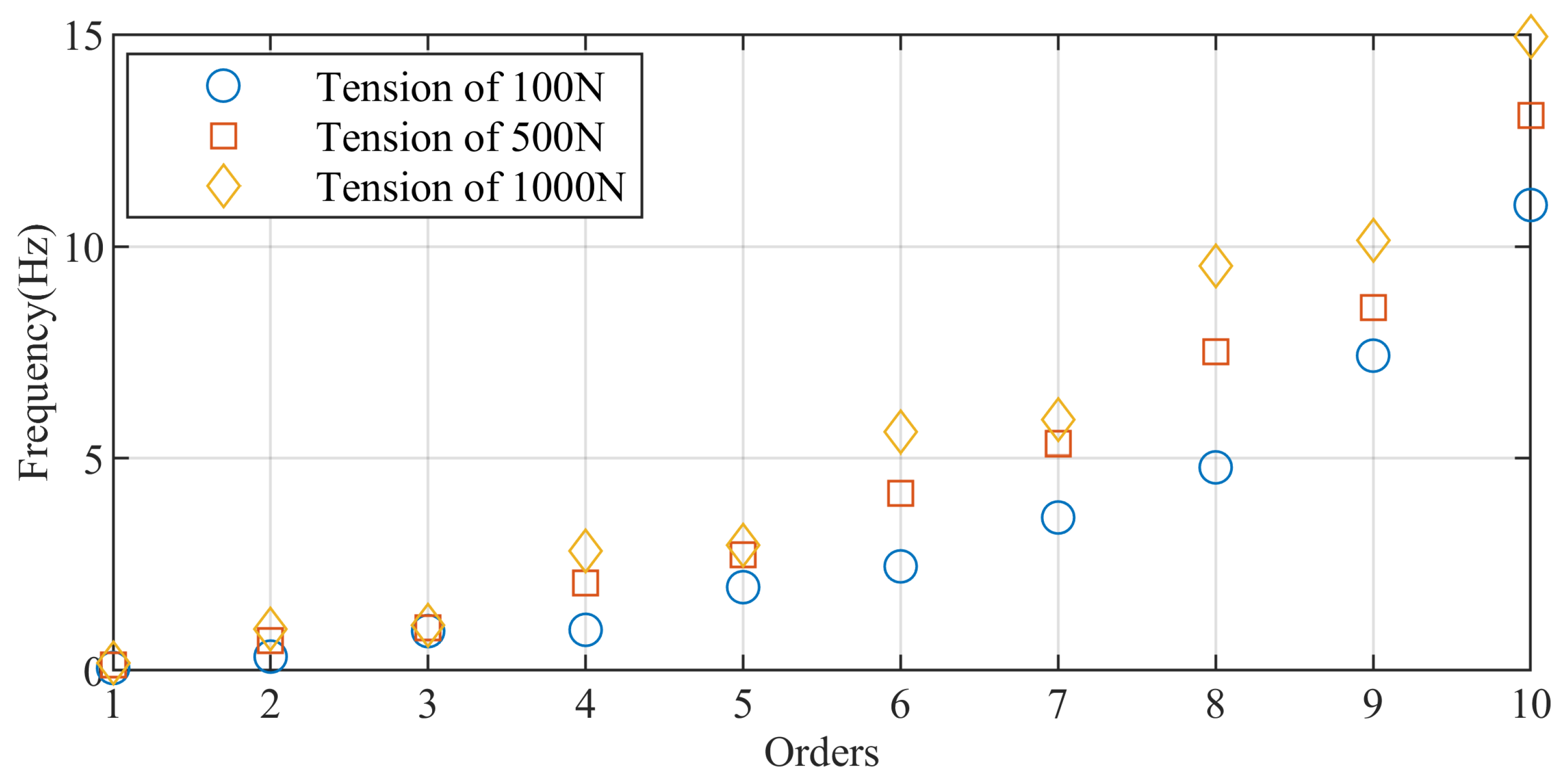
where M is the generalized mass matrix of the manipulator system. Equation (36) can obtain the frequencies of different orders of the system, among which the first-order fundamental frequency is the lowest, which often has a greater impact on system control and characteristics. The change of the driving cable tension will affect the change of K θ , which will affect the system frequency. Figure 9 shows the 1 10 -order frequencies of the system when the cable drive tension is 100 N , 500 N , and 1000 N , respectively. The first-order frequencies were 0.057 Hz, 0.124 Hz and 0.172 Hz, respectively. It can be seen that when the tension was larger, the fundamental frequency of the system would also increase, but the increase in the fundamental frequency would not be as obvious as the stiffness factor.

5.4. Dynamics Simulation

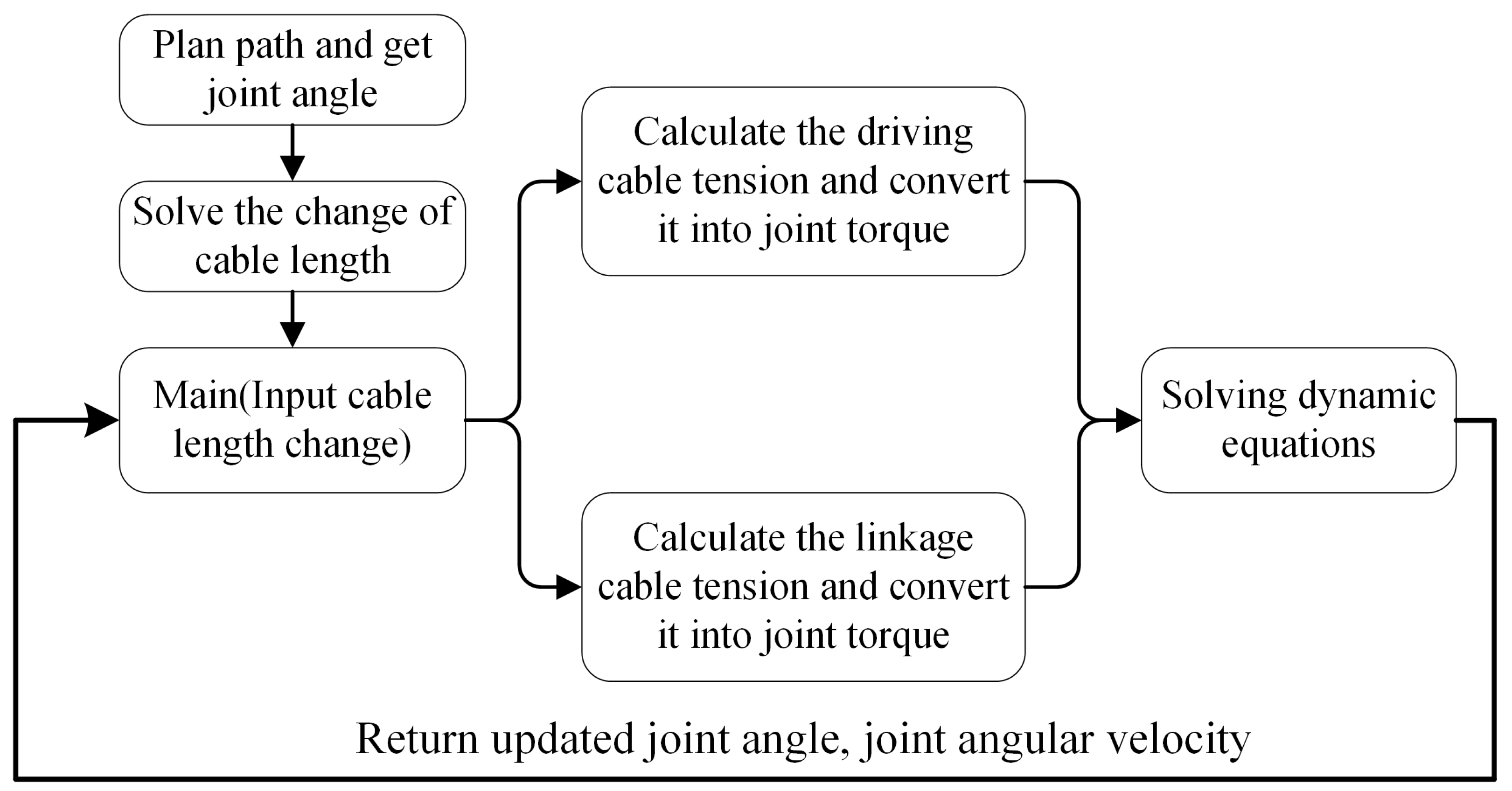
In this section, we carry out the dynamic simulation analysis of the manipulator, and the simulation flowchart is shown in Figure 10. Firstly, the joint angle and the change of the cable length at each moment were obtained by the kinematics planning algorithm. The cable length variation was used as the input of the main program, and the joint angle and angular velocity were initialized. Then, we calculated the response of two types of cables and converted them into the joint torque input to the dynamic equation to solve the joint angle and the angular velocity at the next moment. Using the Matlab + Adams co-simulation, the simulation interface is shown in Figure 11.
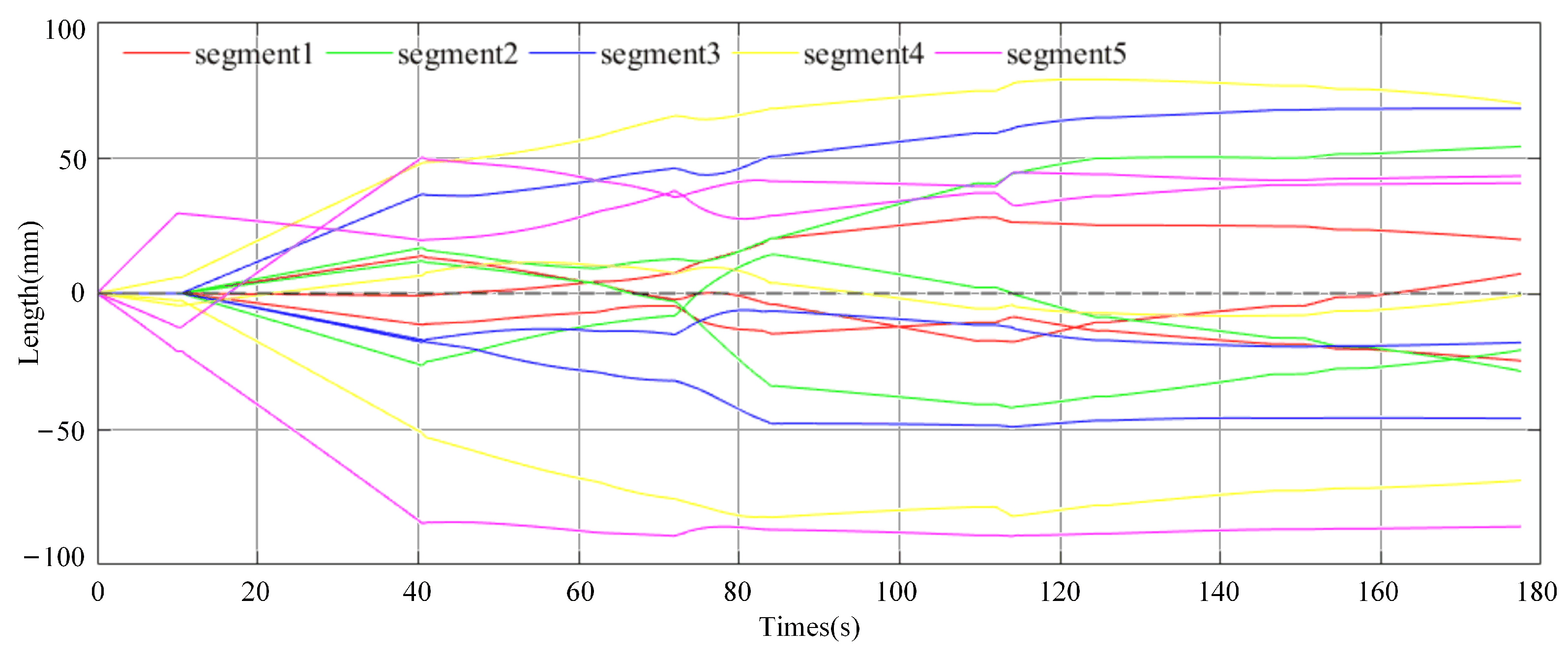
The length change curve of the driving cable solved according to the end task trajectory is shown in Figure 12. One segment was controlled by three cables (the curve represented by the same color in the Figure 12). It can be seen from the planning curve that the change of the cable length will not appear in the same segment of the three driving cables in the same direction, which is consistent with the actual work. It can be seen from the figure that the length change of the cable during the whole movement of the manipulator was less than 100 mm, and the closer to the base, the smaller the length change of the driving cable was.
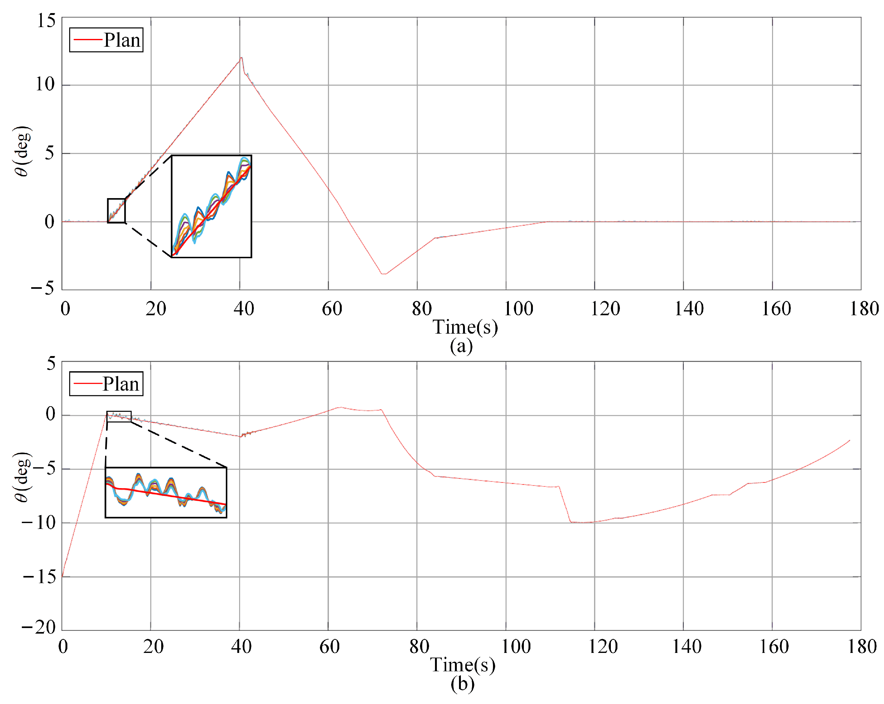
The dynamic simulation results are shown in Figure 13, Figure 14, Figure 15, Figure 16, Figure 17, Figure 18, Figure 19, Figure 20 and Figure 21. Figure 13, Figure 14 and Figure 15 show the comparison between the joint angle simulation and the planning curve in the alpha and beta direction (These two directions represent the two orthogonal deflection directions of the manipulator respectively.) in the 1st, 3rd, and 5th segments of the manipulator. Each figure contains a planning curve and the alpha or beta angle simulation curve of the six cross-axis joints in the segment. It can be seen from the diagram that the linkage cable dynamics’ constraint simulated the joint synchronous rotation effect well. When the manipulator took
About 10 s to lift, the joint showed a certain degree of jitter, which was caused by the 700 g tool installed at the end of the manipulator.
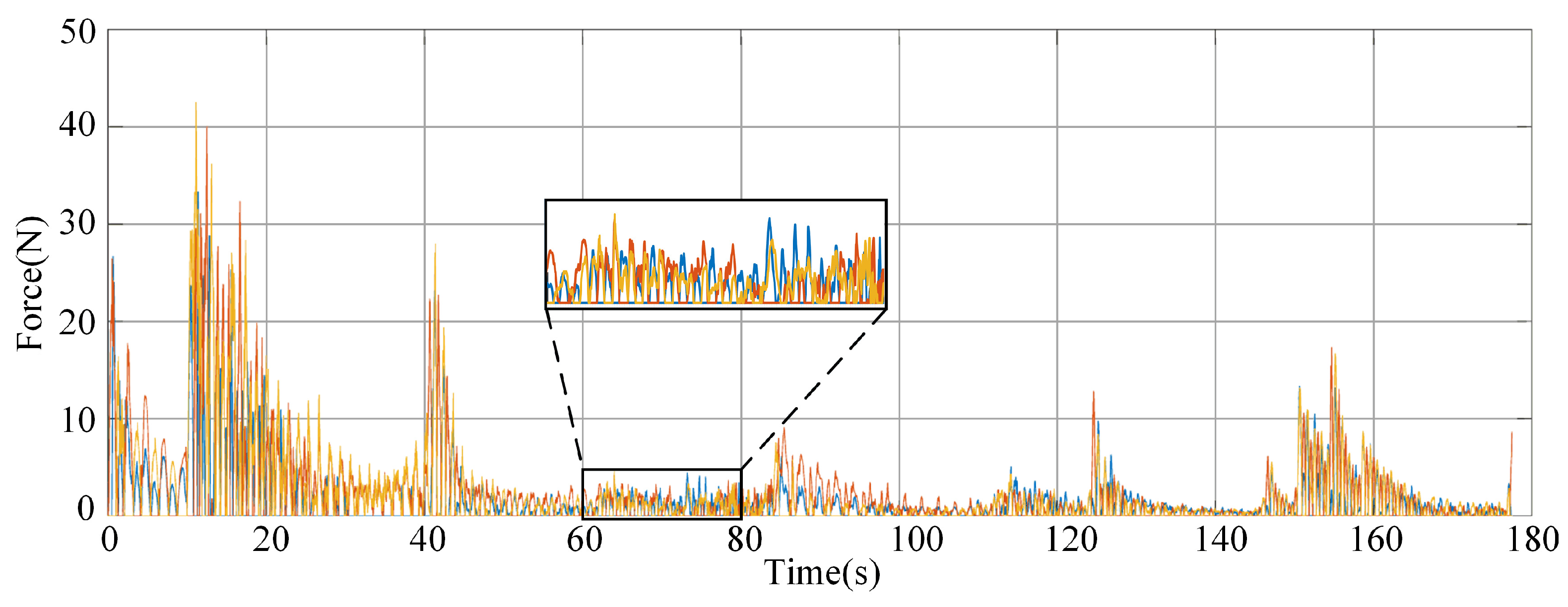
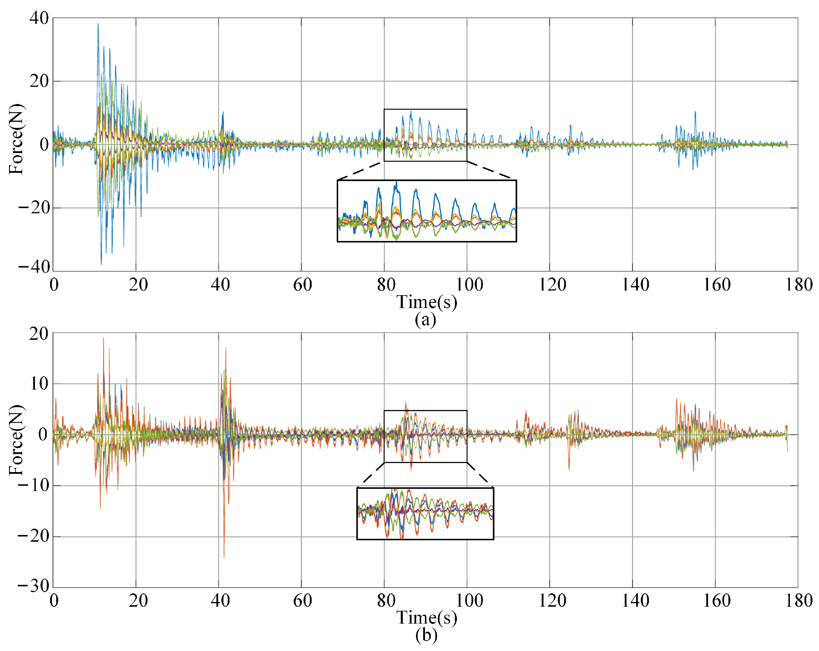
Figure 16, Figure 17 and Figure 18 show the tension curve of each group of driving cables (three cables in each group) corresponding to the 1st, 3rd, and 5th segments, respectively. It can be seen from the results that the maximum cable tension was about 70 N during the whole dynamic motion, and in most cases, it was lower than 50 N . The tension of each cable basically increased suddenly at about 10 s, which was related to the obvious jitter of joint angle at 10 s. This indicated that the excessive tension of driving cable will cause the system to be unstable, and the tension and mutation of the driving cable should be controlled as much as possible in the planning and control process.
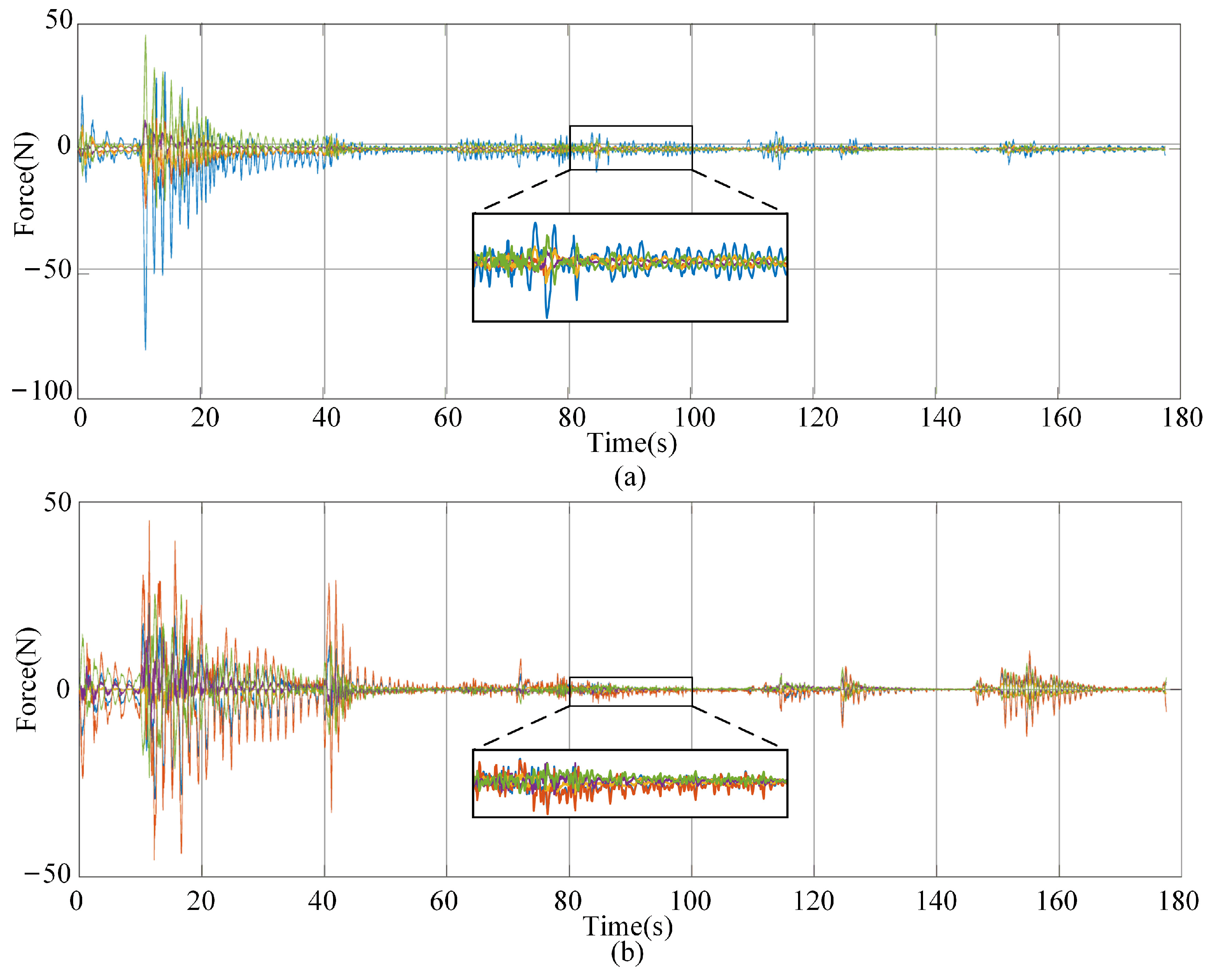
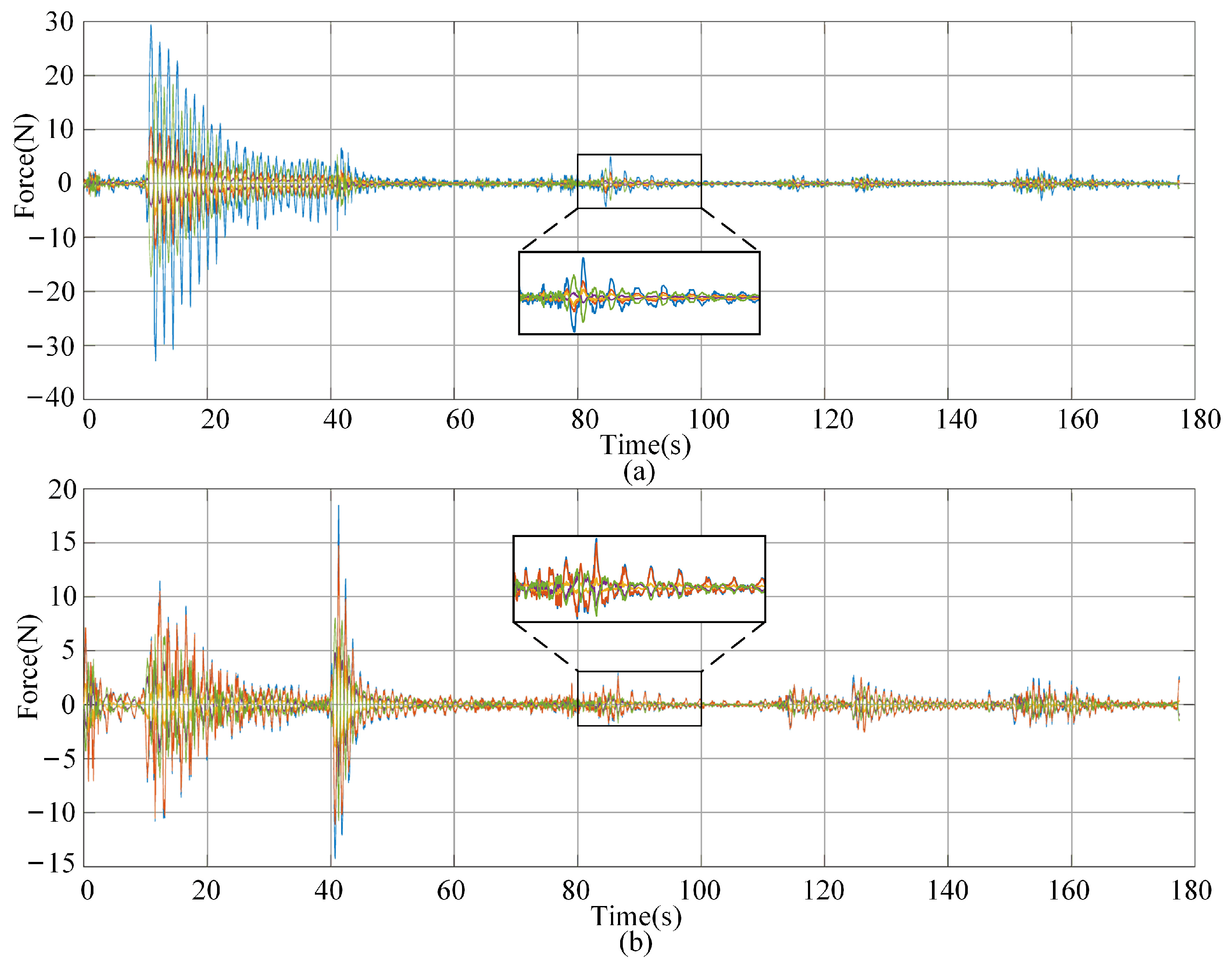
Figure 19, Figure 20 and Figure 21 show the tension curve of the linkage cable corresponding to the 1st, 3rd, and 5th segments, respectively. The tension of the linkage cable was also divided into alpha and beta direction. For the linkage cable of the same segment, the curve of five linkage cables in the same direction is drawn in the same figure. It can be seen from the results that the maximum tension of the cable did not exceed 80 N in the whole motion path.

5.5. Slit Crossing Experiment

The typical working environment of the cable-driven manipulator is a narrow space. In this paper, the dynamic simulation of the satellite sailboard slit crossing scene was carried out for the cable-driven manipulator. The height of the end tool and the maximum outer diameter of link were both 35 mm, and the minimum slit height of the sailboard was 47 mm. Therefore, the manipulator had only a ± 6 mm tolerance in the vertical slit direction. After the end of the manipulator entered the slit, the vibration caused by the flexibility of the manipulator itself (caused by the synchronous rotating cable and driving cable) caused a certain oscillation at the end. Therefore, it was necessary to analyze whether the end would interfere with the upper and lower surfaces of the slit after entering the slit.
The schematic diagram of the drilling slit is shown in Figure 22. Figure 23 shows the end trajectory after entering the slit and the safety line. The Y direction represents the height relative to the lower surface of the slit; the X direction represents the coordinates pointing to the target direction along the slit surface; the blue solid line represents the trajectory of the center of the end; the blue dotted line represents the trajectory of the upper and lower surfaces of the end; the red line represents the safety line of motion (width of 47 mm).
As shown in the figure, during the movement of the manipulator, the maximum oscillation amplitude at the end was 3.8 mm, less than 6 mm, so it theoretically met the task requirements. However, the current trajectory was not in the center of the slit, so some of the movement was beyond the red safety line.

6. Conclusions

The SCCM has important application value in many fields such as on-orbit service and deep space exploration. It is especially suitable for solving the operational problems faced by the unstructured narrow environment of space. The stiffness of the SCCM comes from two parts: linkage cables and driving cables. The stiffness of the driving cables is not only related to the physical parameters of the cable itself, but also related to the cable tension. Therefore, the manipulator can change its stiffness characteristics by adjusting the tension of the driving cable, which can be used for the stiffness control of the manipulator. In addition, the dynamic modeling method was also studied. This paper proposed a co-modeling method combining a dynamic algorithm and software. The cable and friction model were expressed by the algorithm, and the rigid body model of link was established by the Adams software. The dynamic simulation analysis of the task trajectory was carried out by using the established dynamic model. The simulation results showed that the designed SCCM can meet the needs of slit crossing. The main results of this paper are summarized as follows:
  • We established the complete stiffness model of the SCCM and analyzed the stiffness characteristics of the end under a specific configuration based on the stiffness model. The stiffness of the manipulator came from two parts: linkage cables and driving cables. The stiffness of the driving cable was not only related to the physical parameters of the cable itself, but also related to the tension of the cable. Based on the stiffness model, the influence of the active tension of cable on the stiffness of the robot was discussed, which provided the basis for the next stiffness control.
  • A co-modeling and co-simulation method of the SCCM’s dynamics was proposed, which not only ensured the accuracy of the simulation, but also greatly improved the modeling efficiency. The manipulator not only had many DOFs, but also had a large number of cable units. The dynamic modeling was carried out by combining the algorithm with commercial software, which can give full play to the advantages of the rigid model calculation of the dynamic commercial software and ensure the efficiency of the cable friction calculation. This method is suitable for model expansion for large-scale system co-simulation, which greatly reduces the simulation workload.
There are many technical problems involved in the SCCM, and many problems need to be further studied. For example, the joint synchronous rotation mechanism of the cable constraint involves many factors such as cable elasticity and friction force. The friction force will affect the tension distribution of the constraint cable and cause the motion hysteresis of the manipulator in the opposite direction. Therefore, this part needs to be finely processed to obtain a more accurate dynamic model of the SCCM. In addition, due to the use of the cable drive mode and the measuring device being located in the rear drive box, the vibration information of the elastic link of the flexible manipulator cannot be directly obtained. In addition, the implementation of vibration control also needs to be carried out through the drive cable. Therefore, the vibration control of the cable-driven slender elastic manipulator is a difficult problem. It is necessary to fully analyze the vibration characteristics of the system and use the existing drive motor and cable tension sensor for vibration control implementation.

Author Contributions

Conceptualization, D.M. and X.W.; methodology, H.X. and Y.L.; resources, X.L.; writing—original draft, H.X.; writing—review and editing, D.M. All authors have read and agreed to the published version of the manuscript.

Funding

This research was funded by the Guangdong Basic and Applied Basic Research Foundation (2022A1515010543), the State Key Laboratory of Robotics and Systems (HIT) (SKLRS-2023-KF-22), and the University-Industry Collaborative Education Program (220506429202244).

Institutional Review Board Statement

Not applicable.

Informed Consent Statement

Not applicable.

Data Availability Statement

Not applicable.

Conflicts of Interest

The authors declare no conflict of interest.

References

  1. McMahan, W.; Jones, B.; Walker, I. Design and implementation of a multi-section continuum robot: Air-Octor. In Proceedings of the 2005 IEEE/RSJ International Conference on Intelligent Robots and Systems, Edmonton, AB, Canada, 2–6 August 2005; pp. 2578–2585. [Google Scholar] [CrossRef]
  2. Qi, P.; Qiu, C.; Liu, H.; Dai, J.S.; Seneviratne, L.D.; Althoefer, K. A Novel Continuum Manipulator Design Using Serially Connected Double-Layer Planar Springs. IEEE/ASME Trans. Mechatron. 2016, 21, 1281–1292. [Google Scholar] [CrossRef]
  3. Gao, G.; Wang, H.; Xia, Q.; Song, M.; Ren, H. Study on the load capacity of a single-section continuum manipulator. Mech. Mach. Theory 2016, 104, 313–326. [Google Scholar] [CrossRef]
  4. Li, Z.; Wu, L.; Ren, H.; Yu, H. Kinematic comparison of surgical tendon-driven manipulators and concentric tube manipulators. Mech. Mach. Theory 2017, 107, 148–165. [Google Scholar] [CrossRef]
  5. Yang, J.; Peng, H.; Zhou, W.; Zhang, J.; Wu, Z. A modular approach for dynamic modeling of multisegment continuum robots. Mech. Mach. Theory 2021, 165, 104429. [Google Scholar] [CrossRef]
  6. Ning, K.; Wörgötter, F. Control System Development for a Novel Wire-Driven Hyper-Redundant Chain Robot, 3D-Trunk. IEEE/ASME Trans. Mechatron. 2012, 17, 949–959. [Google Scholar] [CrossRef]
  7. Tonapi, M.M.; Godage, I.S.; Walker, I.D. Next generation rope-like robot for in-space inspection. In Proceedings of the 2014 IEEE Aerospace Conference, Big Sky, MT, USA, 1–8 March 2014; pp. 1–13. [Google Scholar] [CrossRef]
  8. Wooten, M.B.; Walker, I.D. A Novel Vine-Like Robot for In-Orbit Inspection. In Proceedings of the 45th International Conference on Environmental Systems, Bellevue, WA, USA, 12 July 2015. [Google Scholar]
  9. Nahar, D.; Yanik, P.M.; Walker, I.D. Robot tendrils: Long, thin continuum robots for inspection in space operations. In Proceedings of the IEEE Aerospace Conference, Big Sky, MT, USA, 4–11 March 2017; pp. 1–8. [Google Scholar] [CrossRef]
  10. Xu, W.; Mu, Z.; Liu, T.; Liang, B. A modified modal method for solving the mission-oriented inverse kinematics of hyper-redundant space manipulators for on-orbit servicing. Acta Astronaut. 2017, 139, 54–66. [Google Scholar] [CrossRef]
  11. Dong, X.; Axinte, D.; Palmer, D.; Cobos, S.; Raffles, M.; Rabani, A.; Kell, J. Development of a slender continuum robotic system for on-wing inspection/repair of gas turbine engines. Robot. Comput. Integr. Manuf. 2017, 44, 218–229. [Google Scholar] [CrossRef]
  12. Peng, J.; Xu, W.; Liu, T.; Yuan, H.; Liang, B. End-effector pose and arm-shape synchronous planning methods of a hyper-redundant manipulator for spacecraft repairing. Mech. Mach. Theory 2021, 155, 104062. [Google Scholar] [CrossRef]
  13. Liu, T.; Mu, Z.; Wang, H.; Xu, W.; Li, Y. A Cable-Driven Redundant Spatial Manipulator with Improved Stiffness and Load Capacity. In Proceedings of the 2018 IEEE/RSJ International Conference on Intelligent Robots and Systems (IROS), Madrid, Spain, 1–5 October 2018; pp. 6628–6633. [Google Scholar] [CrossRef]
  14. Liu, T.; Mu, Z.; Xu, W.; Yang, T.; You, K.; Fu, H.; Li, Y. Improved Mechanical Design and Simplified Motion Planning of Hybrid Active and Passive Cable-Driven Segmented Manipulator with Coupled Motion. In Proceedings of the 2019 IEEE/RSJ International Conference on Intelligent Robots and Systems (IROS), Macau, China, 3–8 November 2019; pp. 5978–5983. [Google Scholar] [CrossRef]
  15. Liu, T.; Xu, W.; Yang, T.; Li, Y. A Hybrid Active and Passive Cable-Driven Segmented Redundant Manipulator: Design, Kinematics, and Planning. IEEE/ASME Trans. Mechatron. 2021, 26, 930–942. [Google Scholar] [CrossRef]
  16. Wang, Y.; Yang, G.; Yang, K.; Zheng, T. The kinematic analysis and stiffness optimization for an 8-DOF cable-driven manipulator. In Proceedings of the 2017 IEEE International Conference on Cybernetics and Intelligent Systems (CIS) and IEEE Conference on Robotics, Automation and Mechatronics (RAM), Ningbo, China, 19–21 November 2017; pp. 682–687. [Google Scholar] [CrossRef]
  17. Oliver-Butler, K.; Till, J.; Rucker, C. Continuum Robot Stiffness Under External Loads and Prescribed Tendon Displacements. IEEE Trans. Robot. 2019, 35, 403–419. [Google Scholar] [CrossRef]
  18. Gu, H.; Wei, C.; Zhang, Z.; Zhao, Y. Theoretical and Experimental Study on Active Stiffness Control of a Two-Degrees-of-Freedom Rope-Driven Parallel Mechanism. J. Mech. Robot. 2021, 13, 011018. [Google Scholar] [CrossRef]
  19. Zhang, J.; Li, Q.; Chen, W.; Fang, Z.; Yang, G. Design and Stiffness Analysis of a Cable-Driven Continuum Manipulator. In Proceedings of the 2021 IEEE 16th Conference on Industrial Electronics and Applications (ICIEA), Chengdu, China, 1–4 August 2021; pp. 2026–2031. [Google Scholar] [CrossRef]
  20. Yuan, H.; Zhang, W.; Dai, Y.; Xu, W. Analytical and numerical methods for the stiffness modeling of cable-Driven serpentine manipulators. Mech. Mach. Theory 2021, 156, 104179. [Google Scholar] [CrossRef]
  21. Xu, W.; Liu, T.; Li, Y. Kinematics, Dynamics, and Control of a Cable-Driven Hyper-Redundant Manipulator. IEEE/ASME Trans. Mechatron. 2018, 23, 1693–1704. [Google Scholar] [CrossRef]
  22. Ma, S.; Liang, B.; Wang, T. Dynamic analysis of a hyper-redundant space manipulator with a complex rope network. Aerosp. Sci. Technol. 2020, 100, 105768. [Google Scholar] [CrossRef]
  23. Zhou, Z.; Zheng, X.; Chen, Z.; Wang, X.; Liang, B.; Wang, Q. Dynamics modeling and analysis of cable-driven segmented manipulator considering friction effects. Mech. Mach. Theory 2022, 169, 104633. [Google Scholar] [CrossRef]
  24. Li, Y.; Liu, Y.; Meng, D.; Wang, X.; Liang, B. Modeling and Experimental Verification of a Cable-Constrained Synchronous Rotating Mechanism Considering Friction Effect. IEEE Robot. Autom. Lett. 2020, 5, 5464–5471. [Google Scholar] [CrossRef]
  25. Hu, Q.; Jia, Y.; Xu, S. A new computer-oriented approach with efficient variables for multibody dynamics with motion constraints. Acta Astronaut. 2012, 81, 380–389. [Google Scholar] [CrossRef]
  26. Hu, Q.; Jia, Y.; Xu, S. Recursive Dynamics Algorithm for Multibody Systems with Variable-Speed Control Moment Gyroscopes. J. Guid. Control. Dyn. 2013, 36, 1388–1398. [Google Scholar] [CrossRef]
Figure 1. Structure diagram of the APCSCM.
Mathematics 11 01874 g001
Figure 2. Short linkage, long linkage, and linkage segment. (a) Short linkage. (b) Long linkage. (c) Overall active and passive linkage segment.
Mathematics 11 01874 g002
Figure 3. The kinematics relationship between the first cross-axis joint and the first group of cables.
Mathematics 11 01874 g003
Figure 4. Definition of the joint coordinate system.
Mathematics 11 01874 g004
Figure 5. Cable hole friction model. (a) Cable and hole contact diagram. (b) Force and motion diagram.
Mathematics 11 01874 g005
Figure 6. Co-modeling schematic.
Mathematics 11 01874 g006
Figure 7. Stiffness simulation.
Mathematics 11 01874 g007
Figure 8. The influence of the driving cable tension on the stiffness.
Mathematics 11 01874 g008
Figure 9. The 1 10 -order frequencies of the manipulator system under different tensions.
Mathematics 11 01874 g009
Figure 10. Dynamic simulation flowchart.
Mathematics 11 01874 g010
Figure 11. Simulation interfaces.
Mathematics 11 01874 g011
Figure 12. Cable length change curve.
Mathematics 11 01874 g012
Figure 13. The comparison between the planning curve and the simulation curve of the six cross-axis joints of the 1st segment. (a) Alpha direction. (b) Beta direction.
Mathematics 11 01874 g013
Figure 14. The comparison between the planning curve and the simulation curve of the six cross-axis joints of the 3rd segment. (a) Alpha direction. (b) Beta direction.
Mathematics 11 01874 g014
Figure 15. The comparison between the planning curve and the simulation curve of the six cross-axis joints of the 5th segment. (a) Alpha direction. (b) Beta direction.
Mathematics 11 01874 g015
Figure 16. Tension curve of three driving cables in the 1st segment.
Mathematics 11 01874 g016
Figure 17. Tension curve of three driving cables in the 3rd segment.
Mathematics 11 01874 g017
Figure 18. Tension curve of three driving cables in the 5th segment.
Mathematics 11 01874 g018
Figure 19. Tension curve of five linkage cables in the 1st segment. (a) Alpha direction. (b) Beta direction.
Mathematics 11 01874 g019
Figure 20. Tension curve of five linkage cables in the 3rd segment. (a) Alpha direction. (b) Beta direction.
Mathematics 11 01874 g020
Figure 21. Tension curve of five linkage cables in the 5th segment. (a) Alpha direction. (b) Beta direction.
Mathematics 11 01874 g021
Figure 22. Slit crossing schematic diagram.
Mathematics 11 01874 g022
Figure 23. End slit crossing trajectory.
Mathematics 11 01874 g023
Table 1. DH parameter table of the s-segment.
Link i s a i mm s α i s d i mm s θ i j
10−900 s θ 1 1  
2 a 1 00 s θ 2 1  
30900 s θ 1 2  
4 a 2 00 s θ 2 2  
⋮  
n s 1 0900 s θ 1 n s  
n s a n s 00 s θ 2 n s  
Table 2. Structure parameters of the links.
Structural ParameterLink of the First Three SegmentsLink of the Latter Two Segments
Mass (mm)9570
Length (mm)85100
Diameter (mm)4035
Center of mass (mm)33.749
Moment–inertia (kg· mm 2 ) 65.73 0 0 0 62.05 0 0 0 19.08 54.15 0 0 0 52.66 0 0 0 7.08
Diameter of cable hole circle (mm)4232
Table 3. Stiffness factor ratio under different tensions.
Different Tension Stiffness Factor Ratios σ F = 100 N / σ F = 0 N σ F = 500 N / σ F = 0 N σ F = 1000 N / σ F = 0 N
Stiffness factor ratio2.82523.088101.498
Disclaimer/Publisher’s Note: The statements, opinions and data contained in all publications are solely those of the individual author(s) and contributor(s) and not of MDPI and/or the editor(s). MDPI and/or the editor(s) disclaim responsibility for any injury to people or property resulting from any ideas, methods, instructions or products referred to in the content.