Article

A Hybrid Reproducing Kernel Particle Method for Three-Dimensional Helmholtz Equation

1
School of Electric Power, Civil Engineering and Architecture, Shanxi University, Taiyuan 030006, China
2
Shanghai Key Laboratory of Mechanics in Energy Engineering, Shanghai Institute of Applied Mathematics and Mechanics, School of Mechanics and Engineering Science, Shanghai University, Shanghai 200072, China
*
Author to whom correspondence should be addressed.
Mathematics 2024, 12(12), 1900; https://doi.org/10.3390/math12121900
Submission received: 5 January 2024 / Revised: 4 June 2024 / Accepted: 17 June 2024 / Published: 19 June 2024

Abstract

:
The reproducing kernel particle method (RKPM) is one of the most universal meshless methods. However, when solving three-dimensional (3D) problems, the computational efficiency is relatively low because of the complexity of the shape function. To overcome this disadvantage, in this study, we introduced the dimension splitting method into the RKPM to present a hybrid reproducing kernel particle method (HRKPM), and the 3D Helmholtz equation is solved. The 3D Helmholtz equation is transformed into a series of related two-dimensional (2D) ones, in which the 2D RKPM shape function is used, and the Galerkin weak form of these 2D problems is applied to obtain the discretized equations. In the dimension-splitting direction, the difference method is used to combine the discretized equations in all 2D domains. Three example problems are given to illustrate the performance of the HRKPM. Moreover, the numerical results show that the HRKPM can improve the computational efficiency of the RKPM significantly.

1. Introduction

The Helmholtz equation is vital in various applications involving time-harmonic wave propagation phenomena. Although mesh-based numerical methods have always played an essential role in analyzing the Helmholtz equation, defects still restrict their development [1,2,3]. Using the finite element method (FEM) decreases the numerical phase accuracy as the wave number decreases. In contrast, the boundary element method (BEM) consumes much computational time due to the need to solve complete and asymmetric algebraic equations.
An alternate strategy is the meshless technique, which may successfully handle some challenging issues related to mesh distortion by using a set of discrete points [4]. After decades of unremitting research by researchers, many meshless methods have emerged [5,6,7,8]. In order to facilitate the comparison of the advantages and disadvantages of various meshless methods, many widely used meshless algorithms have been compared and summarized in certain review studies [9,10]. Among them, the meshless method used in this paper is the reproducing kernel particle method (RKPM) established by Liu et al. [11,12], improving computational accuracy in close proximity to boundaries. In the case of the Helmholtz equation, it has already been proven that the element-free Galerkin method (EFGM) [13,14], the multiple-scale RKPM [15], and the radial point interpolation method (RPIM) [16] provide high computational accuracy for the internal Helmholtz problem.
Although meshless methods can alleviate difficulties associated with mesh preprocessing and distortion in numerical computation, there are attendant drawbacks, such as being time-consuming. The reason meshless methods consume much time in the calculation process is that the calculation of shape functions is computationally intensive. This flaw is especially prominent when analyzing three-dimensional (3D) problems. Researchers have made a great effort to make the meshless techniques work more efficiently. Breitkopf et al. [17] proposed a low-cost approach to calculate the shape function of the meshless method. Krysl and Belytschko [18] describe a shape function library design that can encapsulate the complexity of constructing shape functions.
As a typical meshless method, the RKPM also has the disadvantage of high computational cost, so scholars have begun to seek breakthroughs from various aspects. Zhou et al. [19] improved efficiency by simplifying the calculation of correction coefficients and their derivatives in RKPM. Chen et al. [20] proved that fully integrated RKPM is severely over-constrained in almost incompressible problems. They proposed a pressure projection method to reduce independent discrete constraint equations, improving computational efficiency. Chen and Cheng introduced the complex variable theory and developed the complex variable reproducing kernel particle method (CVRKPM). Compared with traditional RKPM, the advantage of the CVRKPM is that it uses a 1D basis function to establish a correction function for 2D problems in shape function construction, reducing the number of undetermined coefficients in the correction function and effectively improving computational efficiency. Weng et al. solved some 2D problems by applying the CVRKPM.
To improve the computational efficiency of the RKPM, the author has also made some attempts. Among them, the hybrid reproducing kernel particle method (HRKPM) established by incorporating the dimension splitting method (DSM) into the RKPM, which drew inspiration from the idea of Li et al. [21,22,23], achieved more ideal results in improving computational efficiency. In recent years, some people have coupled different meshless methods with the DSM and achieved ideal results. Meng et al. combined the DSM with the improved element-free Galerkin (IEFG) method to solve 3D potential, transient heat conduction and wave propagation problems. Cheng et al. coupled the DSM with the improved complex variable element-free Galerkin (ICVEFG) method to solve 3D potential, transient heat conduction, wave propagation, advection–diffusion and elasticity problems. The IEFG and the ICVEFG methods are based on the moving least-squares (MLS) approximation. The least-squares method is the best approximation, and it has been applied to many engineering problems to obtain solutions with high accuracy [24,25,26,27,28]. So far, we have coupled the DSM with the RKPM to solve 3D potential [29], transient heat conduction [30], wave propagation [31], advection–diffusion [32] and elasticity problems [33] and achieved satisfactory results. In order to expand the research scope, this coupling method is applied to solve the 3D Helmholtz equation.
In this study, we introduced the DSM into the RKPM to present an HRKPM, and the 3D Helmholtz equation is solved. The 3D Helmholtz equation is transformed into a series of related 2D ones, in which the 2D RKPM shape function is used, and the Galerkin weak form of these 2D problems is applied to obtain the discretized equations. In the dimension-splitting direction, the difference method is used to combine the discretized equations in all 2D domains. Three example problems are given to illustrate the performance of the HRKPM. Moreover, the numerical results show that the HRKPM can improve the computational efficiency of the RKPM significantly.

2. The Dimension-Splitting-Governing Equation of 3D Helmholtz Equation

Without loss of generality, the 3D Helmholtz equation inside a domain Ω with a boundary Γ is written as
2 u ( x ) + k 2 u ( x ) = f ( x ) ,   ( x = ( x 1 , x 2 , x 3 ) Ω )
and the boundary conditions can be described as
u ( x ) = u ¯ ( x ) ,   ( x Γ u ) ,
q ( x ) = u ( x ) x 1 n 1 + u ( x ) x 2 n 2 + u ( x ) x 3 n 3 = q ¯ ( x ) ,   ( x Γ q ) ;
where u ( x ) is the complex-valued potential field, and k represents the wave number Γ = Γ u Γ q .
Introducing the dimension splitting method requires selecting an appropriate splitting direction based on the actual situation of the problem to be solved. Without losing generality, the problem domain Ω is assumed to be a cube and select x 3 as the dimension-splitting direction. Then, the Ω is split into L + 1 2D subdomain Ω ( k ) , as shown in Figure 1, the plane where the Ω ( k ) is located can be represented as x 3 = x 3 ( k ) ,
a = x 3 ( 0 ) < x 3 ( 1 ) < < x 3 ( L 1 ) < x 3 ( L ) = b .
The distance between Ω ( k ) and Ω ( k - 1 ) , also known as the dimension-splitting step, is represented by Δ x 3 ,
Δ x 3 = x 3 ( k + 1 ) x 3 ( k ) = ( b a ) / L .
In this way, Figure 1 can be represented by the following equation:
Ω = k = 0 L - 1 Ω ( k ) × [ x 3 ( k ) , x 3 ( k + 1 ) ) Ω ( L ) ,   k = 0 , 1 , , L .
In the Ω ( k ) , the unknown function is u ( k ) = u ( x ( k ) ) . Since x 3 is chosen as the dimension-splitting direction, the independent variable x 3 becomes a known quantity based on the problem domain and the number of splitting steps. Therefore, Equation (1) becomes a partial differential equation with only two independent variables:
2 u ( k ) x 1 2 + 2 u ( k ) x 2 2 = f ( k ) k 2 u ( k ) 2 u ( k ) x 3 2 ,   ( x ( k ) = ( x 1 , x 2 ) Ω ( k ) ) .
The boundary conditions are
u ( k ) = u ¯ ( k ) = u ¯ ( x ( k ) , x 3 ( k ) ) ,   ( x ( k ) Γ u ( k ) ) ,
q ( k ) = q ¯ ( k ) = q ¯ ( x ( k ) , x 3 ( k ) ) ,   ( x ( k ) Γ q ( k ) ) ,
where Γ ( k ) is the boundary of the Ω ( k ) , Γ ( k ) = Γ u ( k ) Γ q ( k ) .
The equivalent functional of Equations (7) and (9) is
Π = Ω ( k ) u ( k ) 2 u ( k ) x 3 2 + 1 2 k 2 u ( k ) f ( k ) d Ω ( k ) Ω ( k ) 1 2 2 u ( k ) x 1 2 + 2 u ( k ) x 2 2 d Ω ( k ) Γ q ( k ) u ( k ) q ¯ ( k ) d Γ ( k )
After applying boundary conditions using the penalty function method, the stationary value problem of the original functional Π with additional conditions is transformed into a stationary value problem of the modified functional Π without additional conditions:
Π = Π + α 2 Γ u ( k ) ( u ( k ) u ¯ ( k ) ) ( u ( k ) u ¯ ( k ) ) d Γ ( k ) ,
where α is the penalty factor.
The stationary condition of Π is that its first variation is equal to zero:
δ Π = Ω ( k ) δ u ( k ) 2 u ( k ) x 3 2 d Ω ( k ) + Ω ( k ) δ u ( k ) k 2 u ( k ) d Ω ( k ) Ω ( k ) δ u ( k ) f ( k ) d Ω ( k ) Ω ( k ) δ ( L u ( k ) ) T ( L u ( k ) ) d Ω ( k ) Γ q ( k ) δ u ( k ) q ¯ d Γ ( k ) + α Γ u ( k ) δ u ( k ) u ( k ) d Γ ( k ) α Γ u ( k ) δ u ( k ) u ¯ ( k ) d Γ ( k ) = 0
where
L ( ) = x 1 x 2 ( ) .

3. The HRKPM Scheme for 3D Helmholtz Equation

There are mainly two steps to obtaining the discrete system equations of the HRKPM. The first step is to obtain the discrete system equations of different subdomains, and the second step is to couple these discrete system equations.
In the first step, we apply the RKPM to construct the approximation function. By using the RKPM, the function u ( x ( k ) ) of any field point x ( k ) in the k-th subdomain can be written as
u h ( x ( k ) ) = I = 1 n Ψ I ( x ( k ) ) u ( x I ( k ) ) = Ψ ( x ( k ) ) u ( k ) ,
where n is the number of nodes which support domain cover the point x ( k ) , and the vector of variable u ( k ) can be expressed as
u ( k ) = ( u ( x 1 ( k ) ) , u ( x 2 ( k ) ) , , u ( x n ( k ) ) ) T ,
and Ψ ( x ( k ) ) is the shape function
Ψ ( x ( k ) ) = ( Ψ 1 ( x ( k ) ) , Ψ 2 ( x ( k ) ) , , Ψ n ( x ( k ) ) ) .
The complete calculation process of the shape function Ψ ( x ( k ) ) has been provided in much of the literature [8] and will not be elaborated on here. Only the selection of the basis function and weight function is given. In the calculation of shape functions, we use a linear basis, and in addition, cubic or quartic spline functions are employed as the weight functions Φ ( z I ) . Among them, z I = x x I d ¯ , d ¯ = d max c I , where c I is a constant representing the distance from x I ( k ) to the nearest node. Therefore, the size of the influence domain can be adjusted by adjusting the value of the scaling parameter d max .
According to Equation (14), the approximate equations for the terms related to u ( k ) in Equation (12) can be obtained as follows:
2 u ( k ) x 3 2 = 2 x 3 2 I = 1 n Ψ I ( x ( k ) ) u ( x I ( k ) ) = I = 1 n Ψ I ( x ( k ) ) 2 u ( x I ( k ) ) x 3 2 = Ψ ( x ( k ) ) u ( k ) ,
L u ( k ) = I = 1 n x 1 x 2 Ψ I ( x ( k ) ) u ( x I ( k ) ) = I = 1 n B I ( x ( k ) ) u ( x I ( k ) ) = B ( x ( k ) ) u ( k ) ,
where
u ( k ) = 2 u ( x 1 ( k ) ) x 3 2 , 2 u ( x 2 ( k ) ) x 3 2 , , 2 u ( x n ( k ) ) x 3 2 T ,
B ( x ( k ) ) = ( B 1 ( x ( k ) ) , B 2 ( x ( k ) ) , , B n ( x ( k ) ) ) ,
B I ( k ) ( x ( k ) ) = Ψ I , 1 ( x ( k ) ) Ψ I , 2 ( x ( k ) ) .
Substituting Equations (14), (17) and (18) into Equation (12) yields
δ Π = Ω ( k ) δ [ Ψ ( x ( k ) ) u ( k ) ] T [ Ψ ( x ( k ) ) u ( k ) ] d Ω ( k ) Γ u ( k ) δ [ Ψ ( x ( k ) ) u ( k ) ] T α u ¯ ( k ) d Γ ( k ) d Ω ( k ) Ω ( k ) δ [ Ψ ( x ( k ) ) u ( k ) ] T f ( k ) d Ω ( k ) Ω ( k ) δ [ B ( x ( k ) ) u ( k ) ] T [ B ( x ( k ) ) u ( k ) ] d Ω ( k ) Γ q ( k ) δ [ Ψ ( x ( k ) ) u ( k ) ] T q ¯ ( k ) d Γ ( k ) + Γ u ( k ) δ [ Ψ ( x ( k ) ) u ( k ) ] T α [ Ψ ( x ( k ) ) u ( k ) ] d Γ ( k ) + Ω ( k ) δ [ Ψ ( x ( k ) ) u ( k ) ] T k 2 [ Ψ ( x ( k ) ) u ( k ) ] d Ω ( k ) = 0 .
The analysis of all integral terms of Equation (22) is presented in the Appendix A.
By rearranging Equation (22), we can obtain the following:
δ u ( k ) T ( S ( k ) u ( k ) + k 2 S ( k ) u ( k ) g ( k ) u ( k ) + g α ( k ) u ( k ) f 1 ( k ) f 2 ( k ) f α ( k ) ) = 0 .
in which
S ( k ) = Ω ( k ) Ψ ( x ( k ) ) T Ψ ( x ( k ) ) d Ω ( k ) ,
g ( k ) = Ω ( k ) B ( x ( k ) ) T B ( x ( k ) ) d Ω ( k ) ,
f 1 ( k ) = Ω ( k ) Ψ ( x ( k ) ) T f ( k ) d Ω ( k ) ,
f 2 ( k ) = Γ q ( k ) Ψ ( x ( k ) ) T q ¯ ( k ) d Γ ( k ) ,
g α ( k ) = Γ u ( k ) Ψ ( x ( k ) ) T α Ψ ( x ( k ) ) d Γ ( k ) ,
f α ( k ) = Γ u ( k ) Ψ ( x ( k ) ) T α u ¯ ( k ) d Γ ( k ) .
Since δ u is arbitrary, the discrete equation for the k-th subdomain can be obtained as
S ( k ) u ( k ) + g ^ ( k ) u ( k ) = f ^ ( k ) ,   ( in   Ω ( k ) ) ,
where
g ^ ( k ) = k 2 S ( k ) + g α ( k ) g ( k ) ,
f ^ ( k ) = f 1 ( k ) + f 2 ( k ) + f α ( k ) .
And the discrete equations for different subdomains are written as follows:
S ( 1 ) u ( 1 ) + g ^ ( 1 ) u ( 1 ) = f ^ ( 1 ) ,   ( in   Ω ( 1 ) ) ,
S ( 2 ) u ( 2 ) + g ^ ( 2 ) u ( 2 ) = f ^ ( 2 ) ,   ( in   Ω ( 2 ) ) ,
S ( L 1 ) u ( L 1 ) + g ^ ( L 1 ) u ( L 1 ) = f ^ ( L 1 ) ,   ( in   Ω ( L 1 ) ) .
In the second step, we need to couple the discrete system equations of different subdomains obtained above. According to the difference method, the field functions of different subdomains can be written as the following equation,
u ( k ) u ( k 1 ) 2 u ( k ) + u ( k + 1 ) ( Δ x 3 ) 2 ,   ( k = 1 , 2 , , L 1 ) ,
then substituting Equation (36) into Equation (30), we obtain the following:
S ( k ) u ( k 1 ) 2 u ( k ) + u ( k + 1 ) ( Δ x 3 ) 2 + g ^ ( k ) u ( k ) = f ^ ( k ) ,   ( in   Ω ( k ) ) ,
and the discrete equations in different subdomains Ω ( k ) can be given by
S ( 1 ) u ( 0 ) 2 u ( 1 ) + u ( 2 ) ( Δ x 3 ) 2 + g ^ ( 1 ) u ( 1 ) = f ^ ( 1 ) ,   ( in   Ω ( 1 ) ) ,
S ( 2 ) u ( 1 ) 2 u ( 2 ) + u ( 3 ) ( Δ x 3 ) 2 + g ^ ( 2 ) u ( 2 ) = f ^ ( 2 ) ,   ( in   Ω ( 2 ) ) ,
S ( L 1 ) u ( L 2 ) 2 u ( L 1 ) + u ( L ) ( Δ x 3 ) 2 + g ^ ( L 1 ) u ( L 1 ) = f ^ ( L 1 ) ,   ( in   Ω ( L 1 ) ) ,
where
u ( 0 ) = u ( x ( 0 ) , a ) ,
u ( L ) = u ( x ( L ) , c ) .
The matrix form of Equations (38)–(40) is
1 Δ x 3 2 N ( 0 ) 0 S ( 1 ) N ( 1 ) S ( 1 ) S ( 2 ) N ( 2 ) S ( 2 ) S ( 3 ) N ( 3 ) S ( 3 ) S ( L 2 ) N ( L 2 ) S ( L 2 ) S ( L 1 ) N ( L 1 ) S ( L 1 ) 0 N ( L ) u ( 0 ) u ( 1 ) u ( 2 ) u ( 3 ) u ( L 2 ) u ( L 1 ) u ( L ) = f ^ ( 0 ) f ^ ( 1 ) f ^ ( 2 ) f ^ ( 3 ) f ^ ( L 2 ) f ^ ( L 1 ) f ^ ( L ) ,
where 0 represents the zero matrix, S ( n ) ( n = 1 , 2 , , L 1 ) is given by Equation (24), N ( k ) ( k = 0 , 1 , , L ) can be given by the following equation:
N ( k ) = 2 S ( k ) + ( Δ x 3 ) 2 g ^ ( k ) ,
f ( n ) ( n = 1 , 2 , , L 1 ) is given by Equation (26), f ^ ( 0 ) and f ^ ( L ) can be represented by
f ^ ( 0 ) = N ( L ) u ( L ) Δ x 3 2 ,
f ^ ( L ) = N ( 0 ) u ( 0 ) Δ x 3 2 .
Let
E = 1 ( Δ x 3 ) 2 N ( 0 ) 0 S ( 1 ) N ( 1 ) S ( 1 ) S ( 2 ) N ( 2 ) S ( 2 ) S ( 3 ) N ( 3 ) S ( 3 ) S ( L 2 ) N ( L 2 ) S ( L 2 ) S ( L 1 ) N ( L 1 ) S ( L 1 ) 0 N ( L ) ,
u ˜ = u ( 0 ) T , u ( 1 ) T , u ( 2 ) T , u ( 3 ) T , , u ( L 2 ) T , u ( L 1 ) T , u ( L ) T T ,
G = f ^ ( 0 ) T , f ^ ( 1 ) T , f ^ ( 2 ) T , f ^ ( 3 ) T , , f ^ ( L 2 ) T , f ^ ( L 1 ) T , f ^ ( L ) T T .
In this way, Equation (43) can be expressed by
E u ˜ = G ,

4. Algorithm Implementation Process

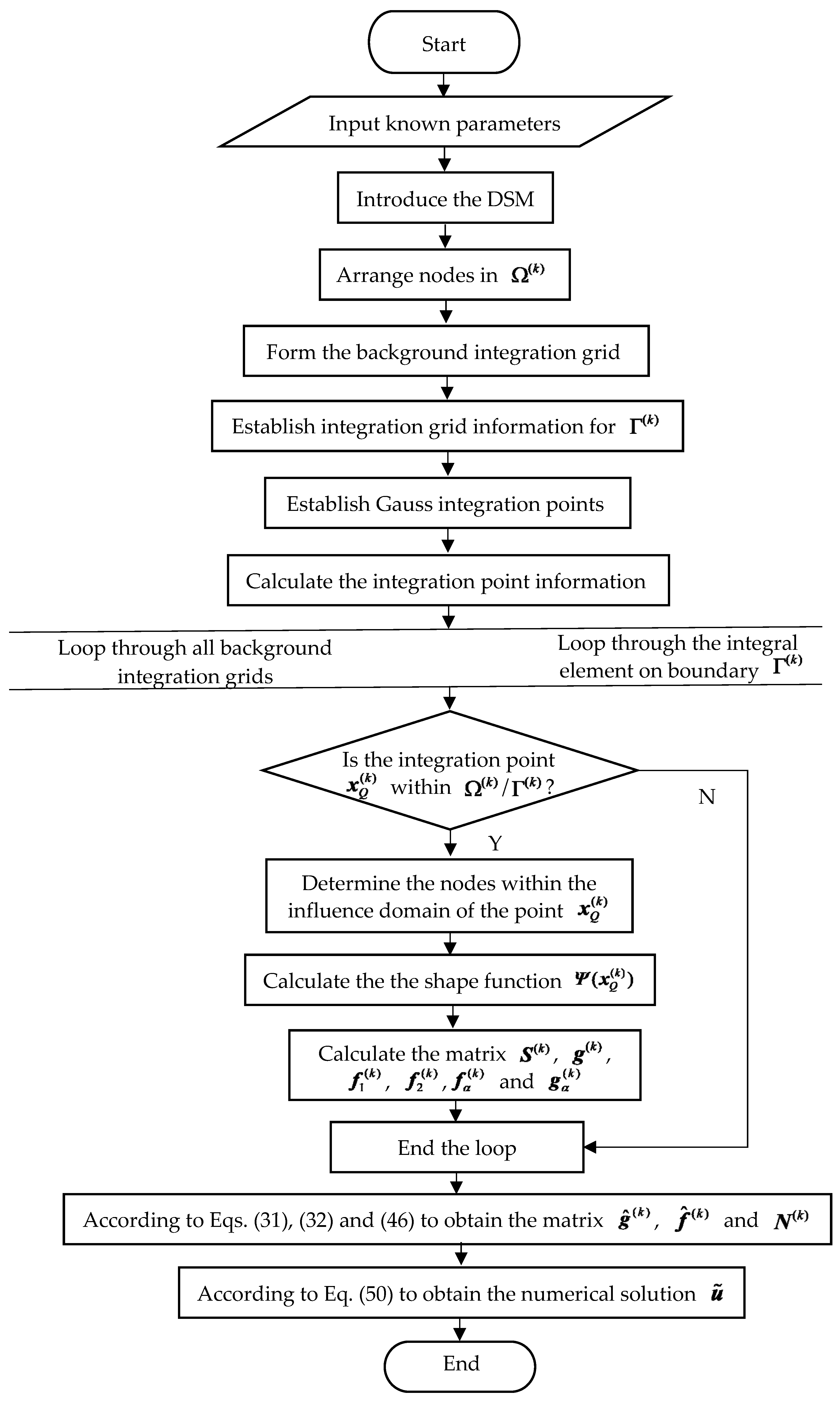
The algorithm implementation process of the HRKPM for the 3D Helmholtz equation is as follows:
(1)
Input known parameters;
(2)
Select the dimension-splitting direction;
(3)
For the splitting 2D Helmholtz equation, determine its variables and coordinate system, arrange nodes on the subdomain Ω ( k ) and boundary Γ ( k ) = Γ u ( k ) Γ q ( k ) , then record node information and node coordinates;
(4)
Establishing the background grid for integration;
(5)
Forming integral element information on boundary Γ ( k ) ;
(6)
Using the background grid and boundary information, establish Gauss integration points and calculate the corresponding integration point information (integration point coordinates, integration weights, and J );
(7)
Generate matrices S ( k ) , g ( k ) and the first term f 1 ( k ) of array f ^ ( k ) ;
(1)
Loop through all background integration grids;
(a)
Loop through all Gaussian integration points within each background grid;
(b)
If the integration point is within Ω ( k ) , run steps (c) to (f); otherwise, run directly to step (f);
(c)
Determine the nodes within the influence domain of the current Gaussian integral point x Q ( k ) ;
(d)
Calculate the numerical values of the shape function Ψ ( x Q ( k ) ) and derivative Ψ I , j ( x Q ( k ) ) at the Gauss integral point x Q ( k ) ;
(e)
Calculate the contribution of the current Gaussian integral point x Q ( k ) to matrices S ( k ) , g ( k ) and f 1 ( k ) using Equations (24), (25) and (26), respectively;
(f)
End the point loop.
(2)
End the background grid loop;
(8)
Numerical integration on boundary Γ u ( k ) : similar to the process in step (7), calculate the second term f 2 ( k ) of the array f ^ ( k ) using Equation (27);
(9)
Numerical integration on boundary Γ u ( k ) : similar to the process in step (7), calculate the third term f α ( k ) of the array f ^ ( k ) and matrix g α ( k ) using Equations (29) and (28);
(10)
According to Equation (32), obtain the final array f ^ ( k ) ;
(11)
According to Equation (31), obtain the final matrix g ^ ( k ) ;
(12)
According to Equation (46), obtain the final matrix N ( k ) ;
(13)
Based on the matrices M ( k ) , g ^ ( k ) , f ^ ( k ) and N ( k ) obtained above, obtain matrices E and G from Equations (47) and (49), respectively;
(14)
Substitute matrices E and G into the equation system (50) to obtain the numerical solution u ˜ .
Figure 2 shows the flowchart of the algorithm implementation process.

5. Numerical Examples

In the previous text, we completed the formula derivation and designed an algorithm implementation process. Then, we need to write corresponding calculation programs based on different examples to verify the proposed method. For the proposed method, we mainly focus on its computational accuracy and efficiency. Evaluate the computational accuracy by the magnitude of the relative error value. Evaluate computational efficiency by comparing the required CPU time under similar computational accuracy.
We define the relative error as
e = u u h L 2 ( Ω ) u L 2 ( Ω ) ,
where
u u h L 2 ( Ω ) = Ω ( u u h ) 2 d Ω 1 / 2 .

5.1. Example 1

The first example is
Δ u + u = sin x 2 cos x 3 ( 12 x 1 2 x 1 4 ) ,
where the problem domain Ω = [ 0 , π ] × [ 0 , π ] × [ 0 , π ] .
The boundary condition is
u ( 0 , x 2 , x 3 ) = 0 ,
u ( π , x 2 , x 3 ) = π 4 sin x 2 cos x 3 ,
u ( x 1 , 0 , x 3 ) = u ( x 1 , π , x 3 ) = 0 ,
u ( x 1 , x 2 , 0 ) = u ( x 1 , x 2 , π ) = x 1 4 sin x 2 .
The analytical solution to this problem is
u ( x ) = x 1 4 sin x 2 cos x 3 .
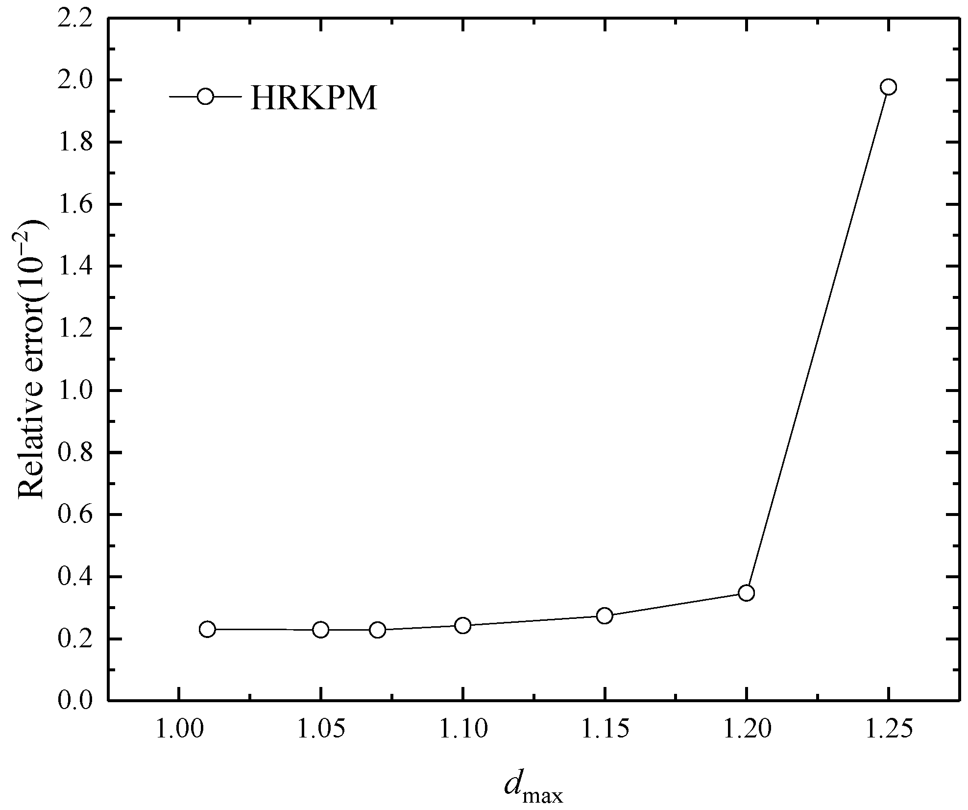
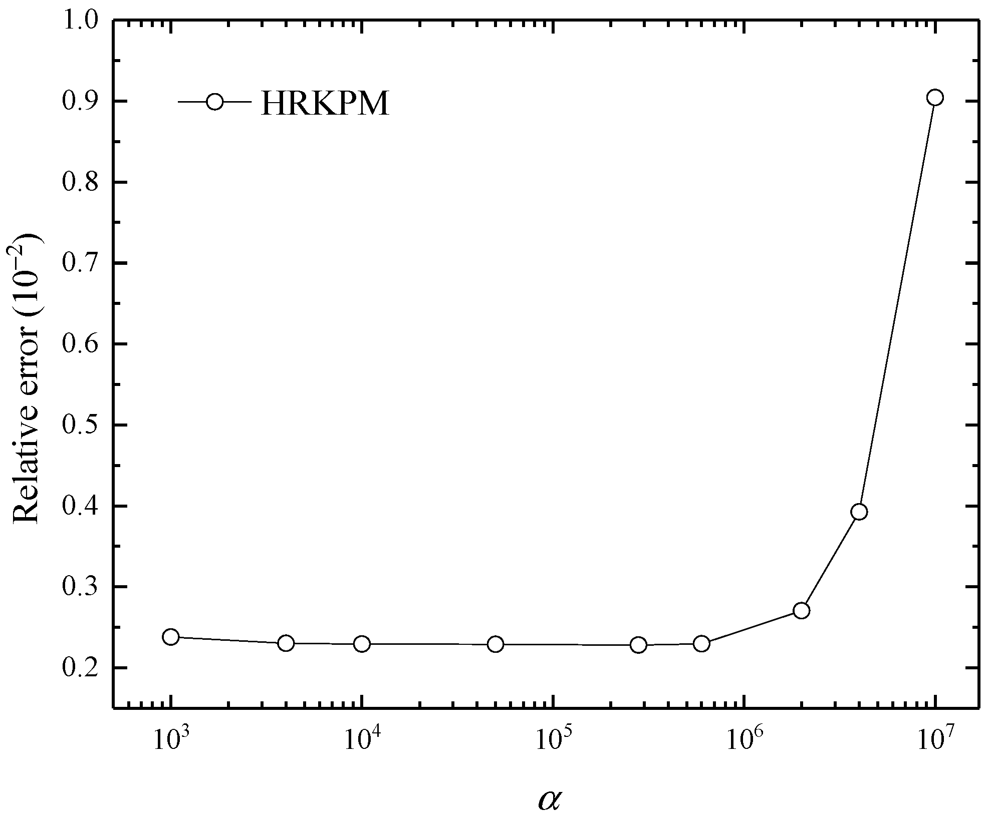
Different parameters have a relatively significant influence on the relative error of the HRKPM, for example, when d max = 1.01 , the relative error is 0.002; when d max = 1.25 , the relative error is 0.02. Therefore, we should grasp the influence of different parameters on the relative error to select the appropriate parameters to obtain higher calculation accuracy. Figure 3, Figure 4, Figure 5 and Figure 6 show the relative errors versus different parameters.
Through the analysis of Figure 2, Figure 3, Figure 4 and Figure 5, it can be found that the influence of some parameters on computational accuracy is regular. In Figure 2 and Figure 3, the relative error decreases with the increase in the number of nodes and the step number, respectively. However, the influence of some parameters on computational accuracy is irregular. In Figure 4 and Figure 5, the relative error value changes irregularly with the change of d max and α , and we can only choose appropriate parameters through continuous attempts. As can be seen from the figures, the computational accuracy is higher when d max is set to 1.01 1.2 , and α is set to 1 × 10 3 4 × 10 6 .
Next, we need to evaluate the computational efficiency of the method based on error analysis. In Table 1, the relative errors and CPU time obtained by the HRKPM and the RKPM under different node distributions are discussed and compared. An analysis of the data in this table explains that the HRKPM is implemented in a more efficient and accurate manner.
In some cases, the CPU time of the numerical method is shortened at the expense of the computational accuracy, so it is meaningless to discuss the computational efficiency solely by comparing the CPU time of two different methods, and the computational efficiency should be demonstrated by comparing the CPU time under same computational accuracy.
When the parameters of RKPM are adjusted to d max = 1.01 , α = 5 × 10 7 and the number of nodes is 15 × 15 × 15 , the relative error is 0.007 and the CPU time is 445.83   s . When the parameters of HRKPM are adjusted to d max = 1.02 , α = 2.7 × 10 7 , L = 14 and the number of nodes in each Ω ( k ) is 15 × 15 , the same relative error can be obtained, with a CPU time of 10.23   s . Comparing the CPU time required to obtain the same relative error between these two methods reveals that HRKPM outperforms RKPM in computational efficiency.
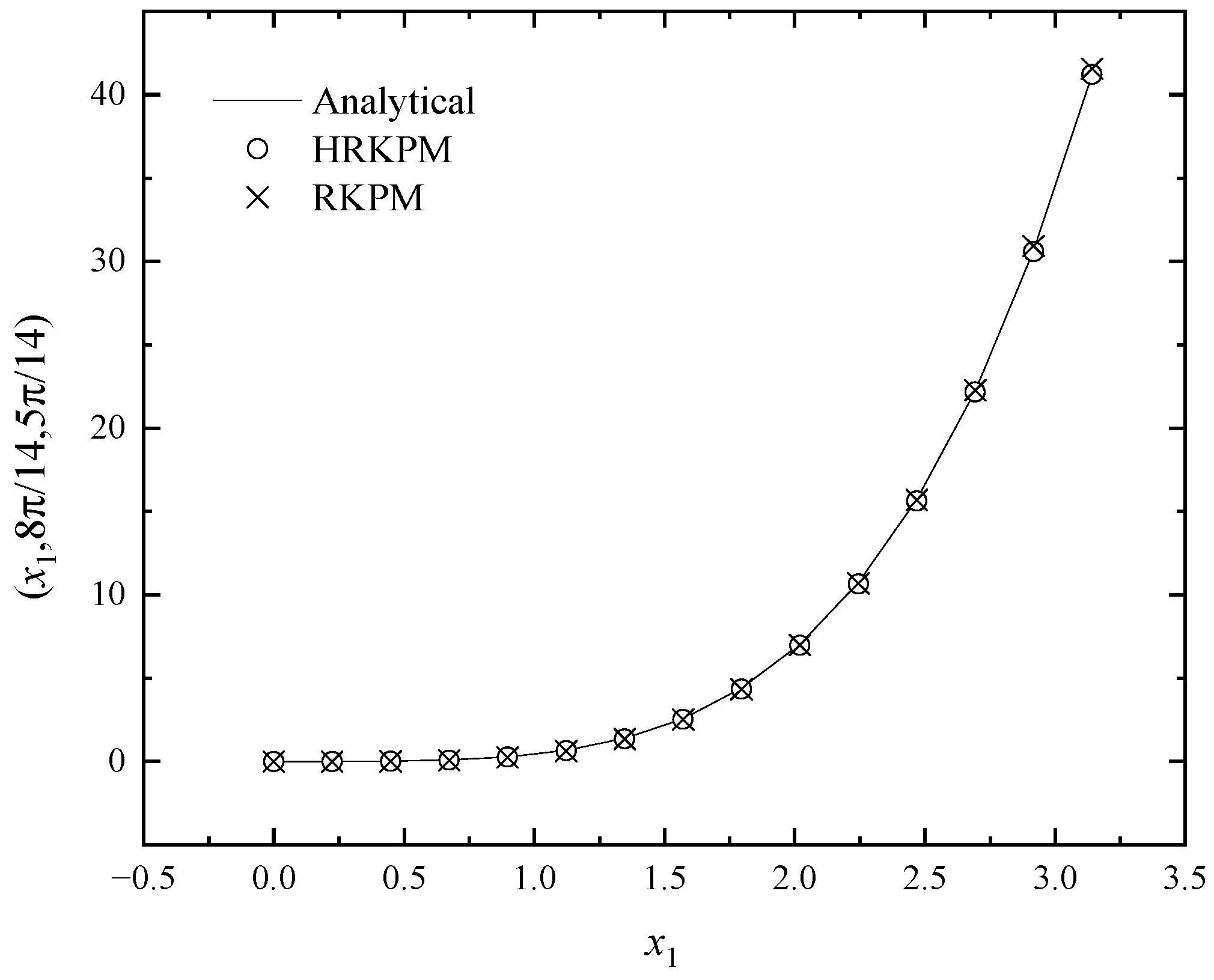
The above are the numerical representations of the results obtained by these two methods. In order to make the results more visualized and intuitive, the image representations of the two methods are shown in Figure 7, Figure 8 and Figure 9. From these figures, it can be revealed that the outcomes of the two methods are highly consistent with the analytical solutions in different directions, but the HRKPM is more efficient than the RKPM.

5.2. Example 2

The second example is
Δ u k 2 u = 0 ,
where the problem domain Ω = [ 0 , 1 ] × [ 0 , 1 ] × [ 0 , 1 ] .
The boundary conditions are
u ( 0 , x 2 , x 3 ) = e ( ξ 2 x 2 + ξ 3 x 3 ) ,
u ( 1 , x 2 , x 3 ) = e ( ξ 1 + ξ 2 x 2 + ξ 3 x 3 ) ,
u ( x 1 , 0 , x 3 ) = e ( ξ 1 x 1 + ξ 3 x 3 ) ,
u ( x 1 , 1 , x 3 ) = e ( ξ 1 x 1 + ξ 2 + ξ 3 x 3 ) ,
u ( x 1 , x 2 , 0 ) = e ( ξ 1 x 1 + ξ 2 x 2 ) ,
u ( x 1 , x 2 , 1 ) = e ( ξ 1 x 1 + ξ 2 x 2 + ξ 3 ) .
The exact solution of this problem is
u = e ( ξ 1 x 1 + ξ 2 x 2 + ξ 3 x 3 ) .
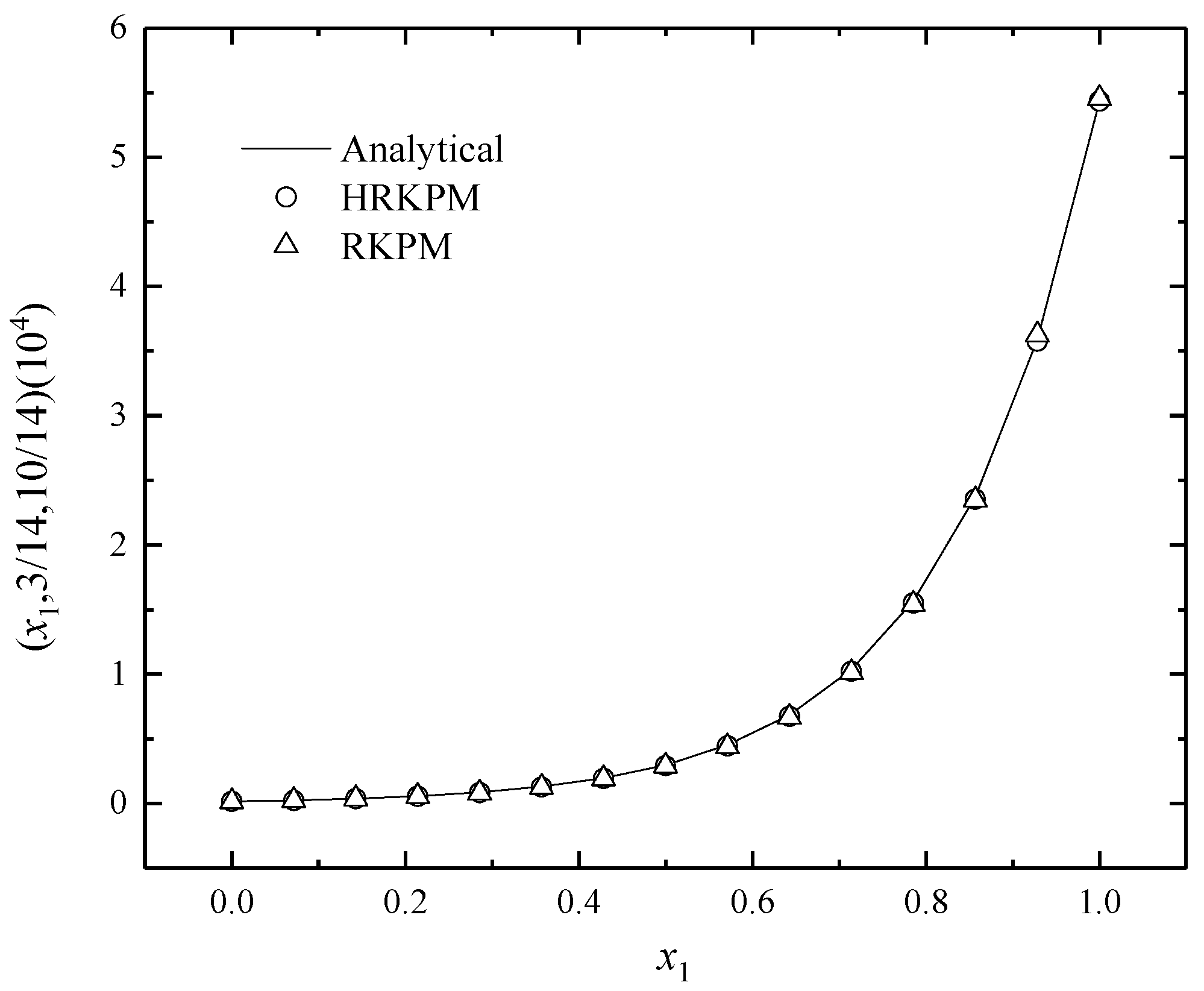
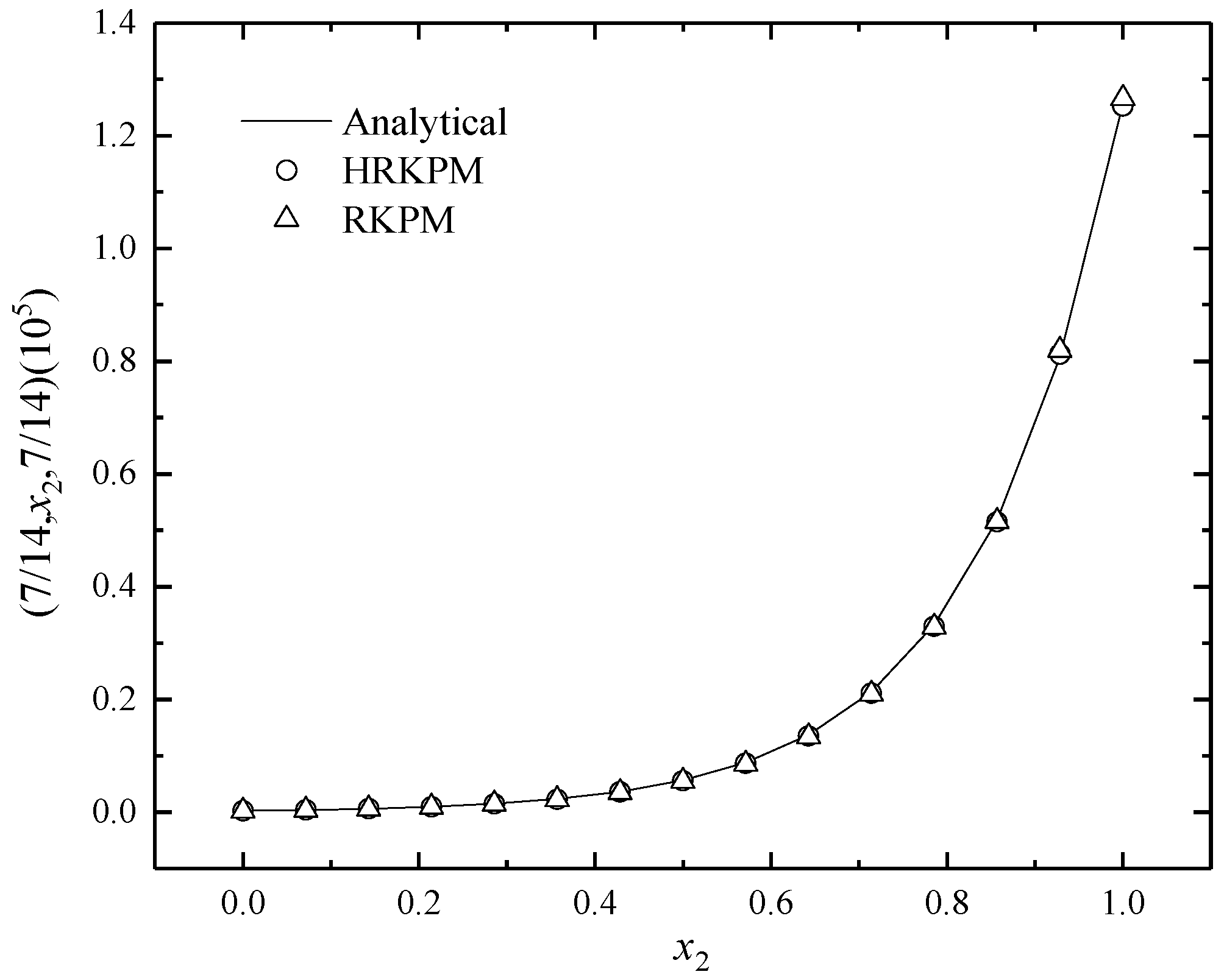
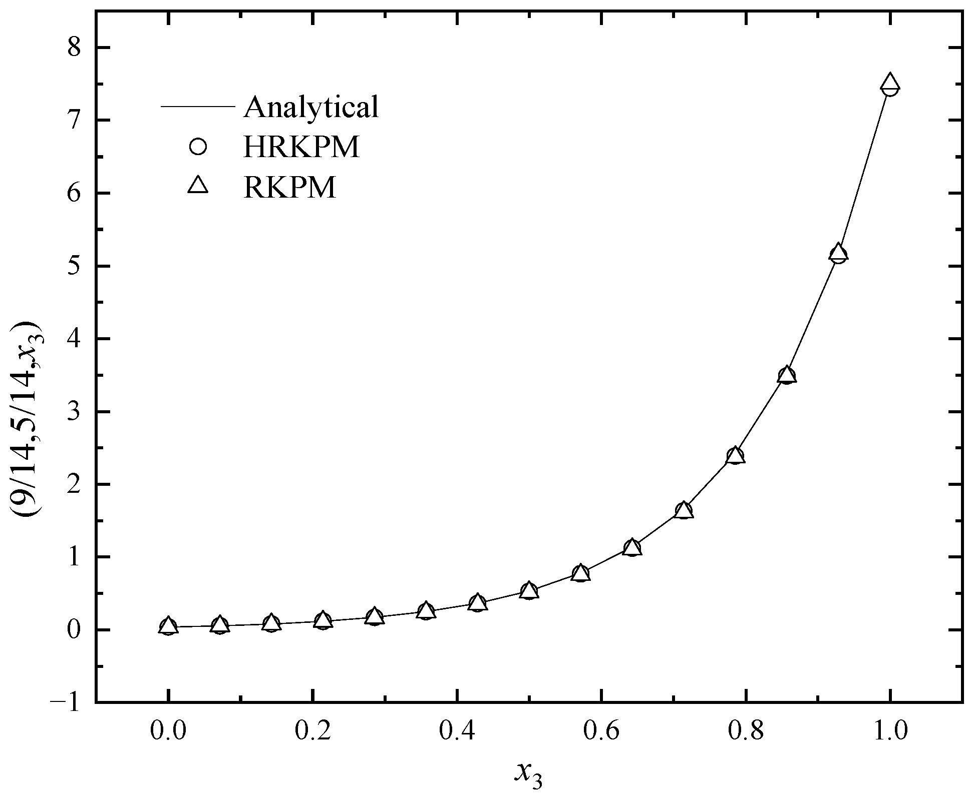
In this example, we set k = 10 , ξ 1 = 5.8 , ξ 2 = 6.2 and ξ 3 = k 2 ξ 1 2 ξ 2 2 . When the parameters of RKPM are adjusted to d max = 1.28 , α = 2.4 × 10 2 and the number of nodes is 15 × 15 × 15 , the relative error is 0.0068 and the CPU time is 204.71 s. When the parameters of HRKPM are adjusted to d max = 1.15 , α = 7.8 × 10 2 , L = 14 and the number of nodes in each Ω ( k ) is 15 × 15 , the same relative error can be obtained, with a CPU time of 3.04   s . Similarly, the CPU time of the HRKPM is significantly shorter than that of the RKPM, indicating that HRKPM has higher computational efficiency than the RKPM.
Figure 10, Figure 11 and Figure 12 give the image representations of the two methods. From these figures, it can be revealed that the outcomes of the two methods are highly consistent with the analytical solutions in different directions, but the HRKPM is more efficient than the RKPM.

5.3. Example 3

The third example is
Δ u + k 2 u = ( k 2 3 π 2 ) cos ( π x 1 ) sin ( π x 2 ) sin ( π x 3 ) ,
where the problem domain is Ω = [ 0 , 1 ] × [ 0 , 1 ] × [ 0 , 1 ] .
The boundary conditions are
u ( 0 , x 2 , x 3 ) x 1 = u ( 1 , x 2 , x 3 ) x 1 = 0 .
u ( x 1 , 0 , x 3 ) = u ( x 1 , 1 , x 3 ) = 0 ,
u ( x 1 , x 2 , 0 ) = u ( x 1 , x 2 , 1 ) = 0 .
The analytical solution of this problem is
u = cos ( π x 1 ) sin ( π x 2 ) sin ( π x 3 ) .
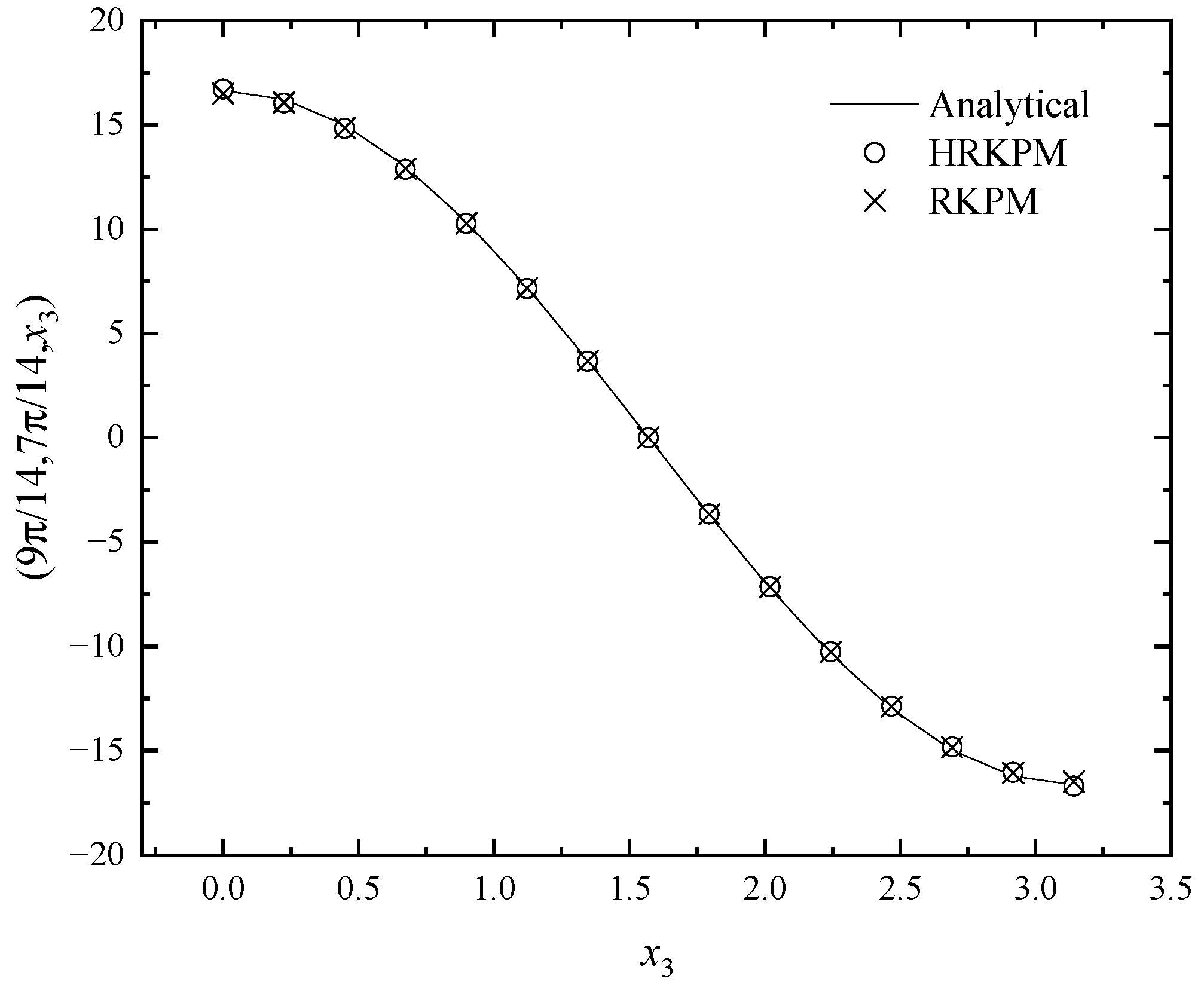
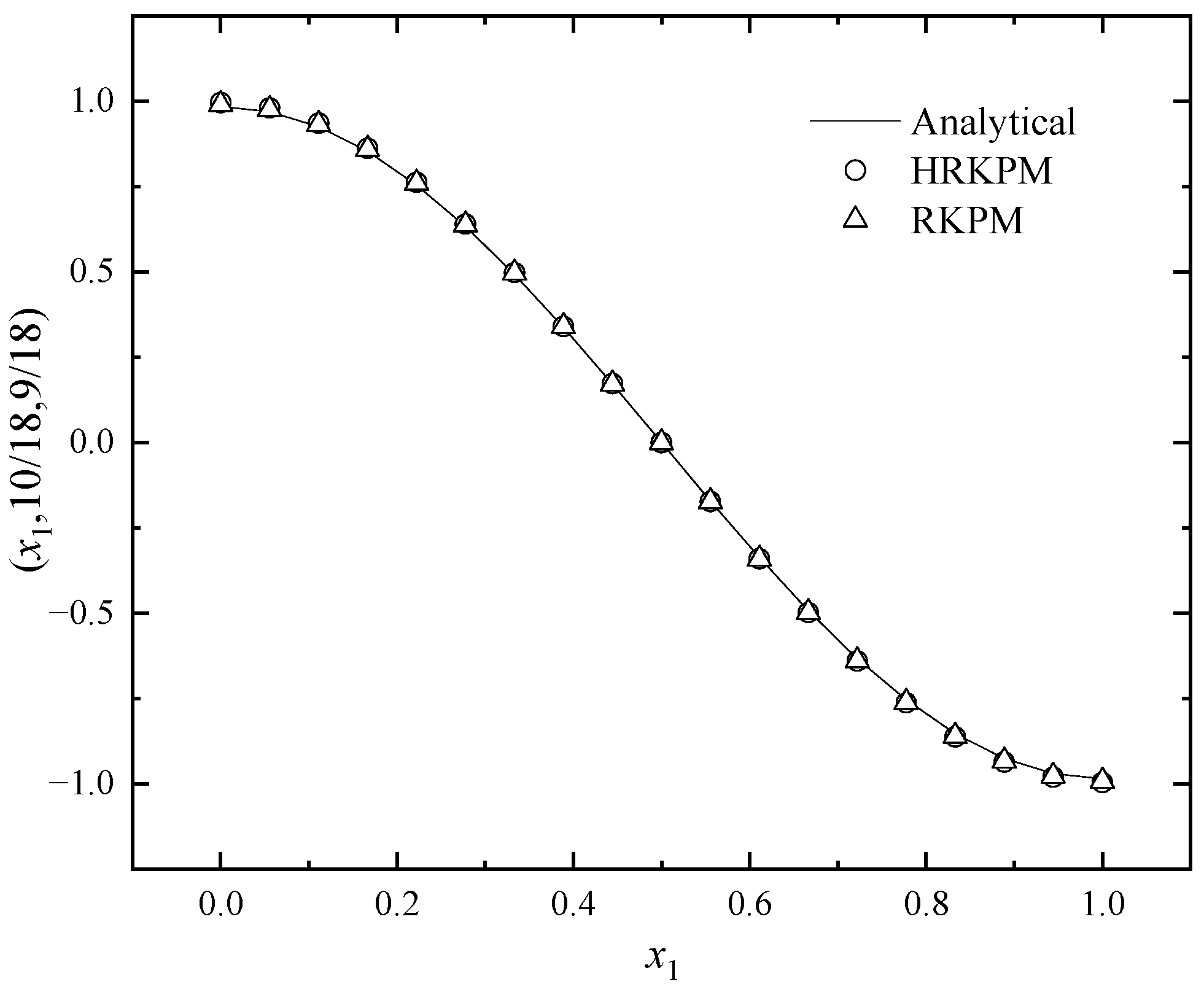
In this example, when the parameters of RKPM are adjusted to d max = 1.01 , α = 3 × 10 6 and the number of nodes is 19 × 19 × 19 , the relative error is 0.0086 and the CPU time is 439.25   s . When the parameters of HRKPM are adjusted to d max = 1.01 , α = 1.88 × 10 3 , L = 18 and the number of nodes in each Ω ( k ) is 19 × 19 , the same relative error can be obtained, with a CPU time of 36.03   s . Similarly, the CPU time of the HRKPM is significantly shorter than that of the RKPM, indicating that HRKPM has higher computational efficiency.
Figure 13, Figure 14 and Figure 15 give the image representations of the two methods. From these figures, it can be revealed that the outcomes of the two methods are highly consistent with the analytical solutions in different directions, but the HRKPM is more efficient than the RKPM.
Table 2 presents the numerical and analytical solutions when x2 = 5/9, x3 = 1/2 and x1 take different values. It can be visually seen from the table that the numerical solutions of the HRKPM, RKPM and IEFG methods are consistent with the analytical solutions in terms of numerical magnitude. However, the CPU time of the three methods is 22.25 s, 439.25 s, and 283.91 s, respectively, indicating that the method established in this paper has higher computational efficiency.

5.4. Example 4

The fourth example is
Δ u + u = 4 3 1 r r 4 sin θ + x 3 ,   ( r [ 1 , 2 ] ,   θ [ 0 , π ] ,   x 3 [ 0 , 1 ] ) .
The boundary conditions are
u ( 1 , θ , x 3 ) = sin θ + x 3 ,
u ( 2 , θ , x 3 ) = x 3 ,
u ( r , 0 , x 3 ) = x 3 ,
u ( r , π , x 3 ) = x 3 ,
u ( r , θ , 0 ) = 4 3 1 r r 4 sin θ ,
u ( r , θ , 1 ) = 4 3 1 r r 4 sin θ + 1 .
The analytical solution to this problem is
u ( r , θ , x 3 ) = 4 3 1 r r 4 sin θ + x 3 .
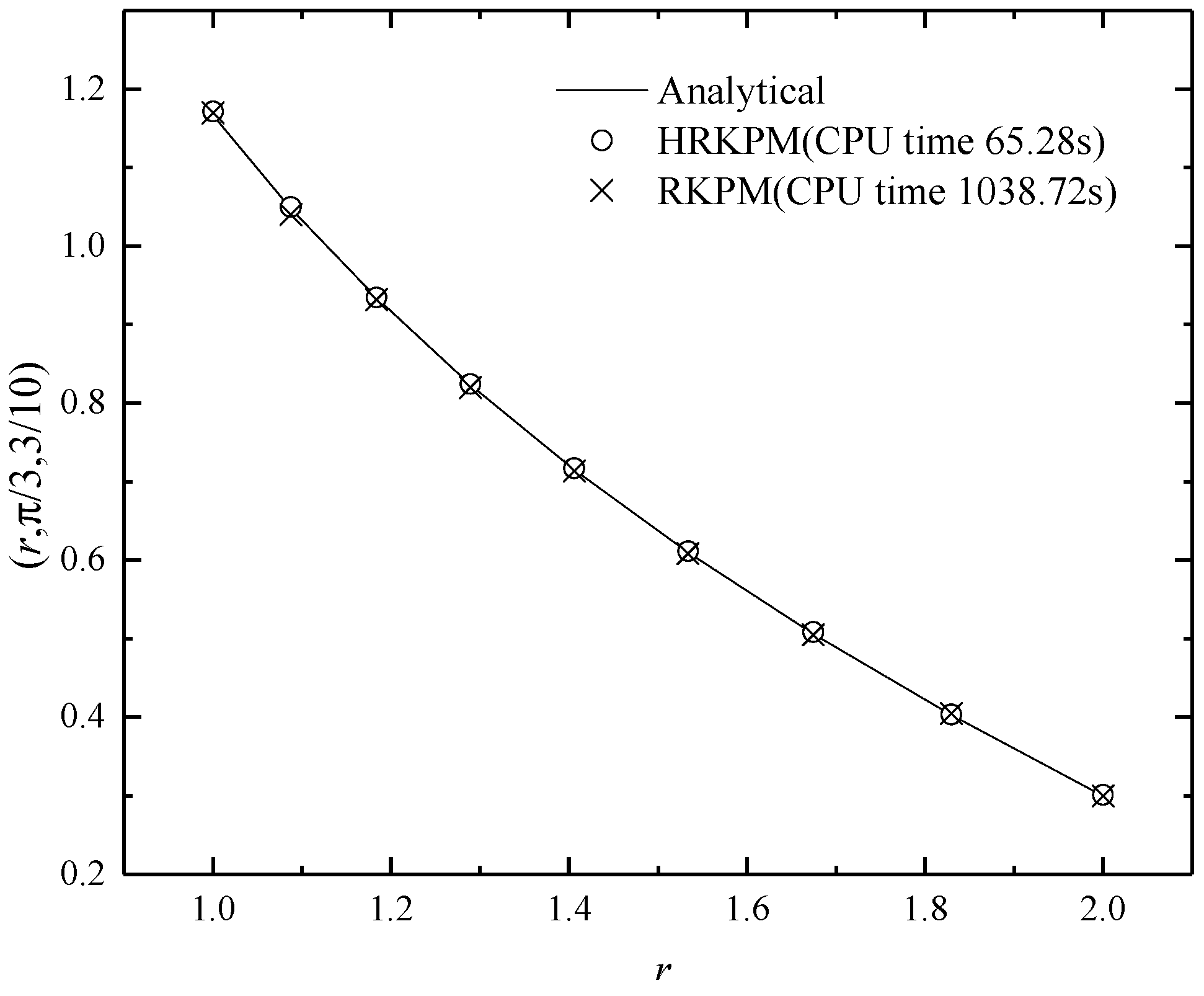
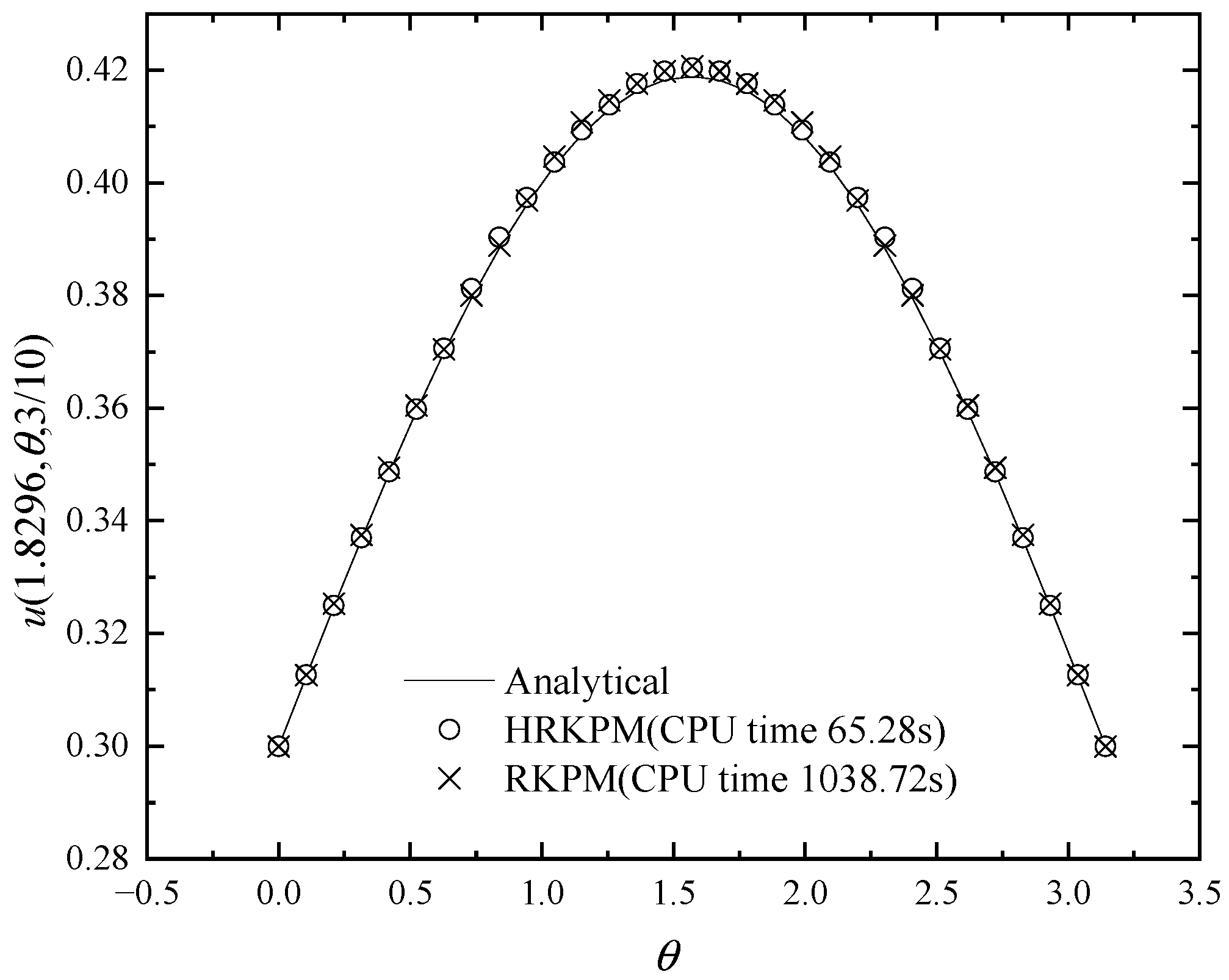
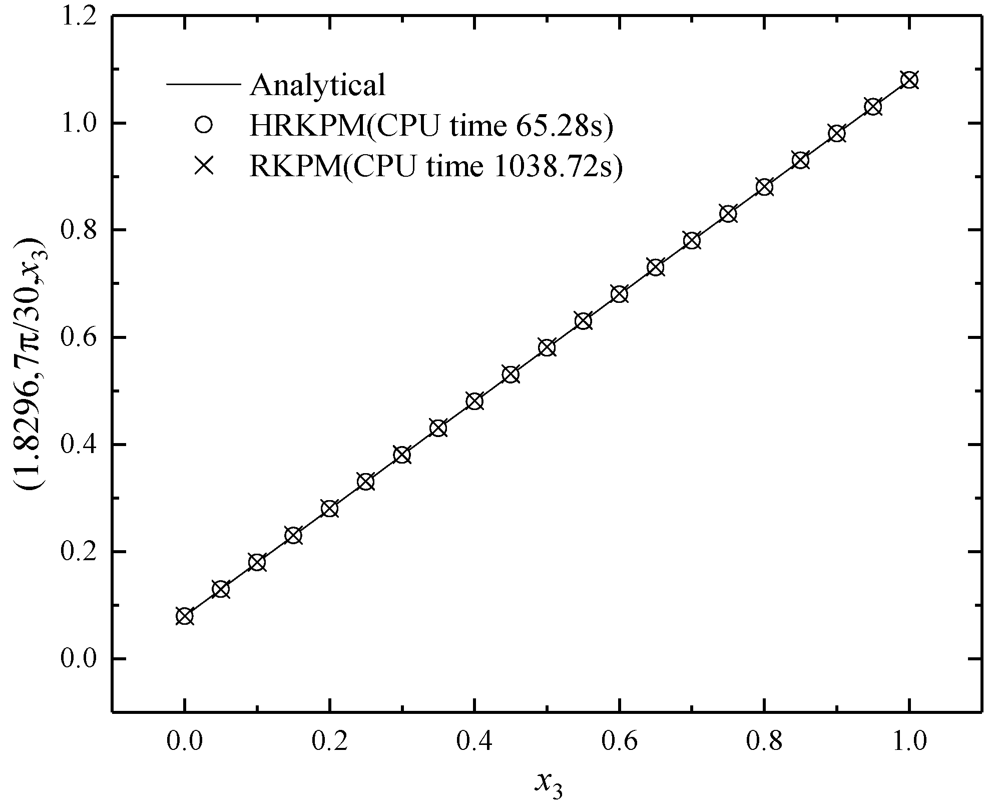
In this example, when the parameters of RKPM are adjusted to d max = 1.01 , α = 1.55 × 10 4 and the number of nodes is 9 × 31 × 21 , the relative error is 0.0026, and the CPU time is 1038.72   s . When the parameters of HRKPM are adjusted to d max = 1.01 , α = 1 × 10 4 , L = 20 and the number of nodes in each Ω ( k ) is 9 × 31 , the same relative error can be obtained, with a CPU time of 65.28   s . Similarly, the CPU time of the HRKPM is significantly shorter than that of the RKPM, indicating that HRKPM has higher computational efficiency.
Figure 16, Figure 17 and Figure 18 give the image representations of the two methods. From these figures, it can be revealed that the outcomes of the two methods are highly consistent with the analytical solutions in different directions, but the HRKPM is more efficient than the RKPM.

6. Conclusions

This paper presents an HRKPM for the 3D Helmholtz equation. Three numerical examples are chosen for this study and solved by the HRKPM and RKPM, respectively.
According to the numerical results, it can be found that the influence of the number of nodes and step number on computational accuracy is regular; that is, the relative error decreases with the increase in the number of nodes and step number. The influence of dmax and α on calculation accuracy is irregular. Through continuous attempts, it can be concluded that the computational accuracy is higher when dmax is set to 1.01~1.2 and α is set to 1 × 10³~1 × 10⁶.
In order to ensure that the computational efficiency is not affected by the accuracy, by comparing the CPU time under the same relative error to evaluate the computational efficiency of the HRKPM, it can be found that the computational efficiency of HRKPM is significantly higher than that of the RKPM.

Author Contributions

Conceptualization, Y.C.; methodology, Y.C.; software, P.P.; writing—original draft preparation, P.P.; writing—review and editing, P.P.; visualization, N.W.; supervision, P.P.; funding acquisition, P.P. All authors have read and agreed to the published version of the manuscript.

Funding

This research was funded by the National Natural Science Foundation of China (grant number 12271341) and the Natural Science Foundation of Shanxi Province (grant number 202203021212484).

Data Availability Statement

The data will be made available by the authors on request.

Conflicts of Interest

The authors declare no conflicts of interest.

Appendix A

Analyzing all integral terms of Equation (22), we have
Ω ( k ) δ [ Ψ ( x ( k ) ) u ( k ) ] T [ Ψ ( x ( k ) ) u ( k ) ] d Ω ( k )   = δ u ( k ) T [ Ω ( k ) Ψ ( x ( k ) ) T Ψ ( x ( k ) ) d Ω ( k ) ] u ( k ) = δ u ( k ) T S ( k ) u ( k )
Ω ( k ) δ [ Ψ ( x ( k ) ) u ( k ) ] T k 2 [ Ψ ( x ( k ) ) u ( k ) ] d Ω ( k )   = δ u ( k ) T [ Ω ( k ) Ψ ( x ( k ) ) T k 2 Ψ ( x ( k ) ) d Ω ( k ) ] u ( k ) = δ u ( k ) T k 2 S ( k ) u ( k )
Ω ( k ) δ [ Ψ ( x ( k ) ) u ( k ) ] T f ( k ) d Ω ( k )   = δ u ( k ) T [ Ω ( k ) Ψ ( x ( k ) ) T f ( k ) d Ω ( k ) ] = δ u ( k ) T f 1 ( k )
Ω ( k ) δ [ B ( x ( k ) ) u ( k ) ] T [ B ( x ( k ) ) u ( k ) ] d Ω ( k )   = δ u ( k ) T [ Ω ( k ) B ( x ( k ) ) T B ( x ( k ) ) d Ω ( k ) ] u ( k ) = δ u ( k ) T g ( k ) u ( k )
Γ q ( k ) δ [ Ψ ( x ( k ) ) u ( k ) ] T q ¯ ( k ) d Γ ( k )   = δ u ( k ) T [ Γ q ( k ) Ψ ( x ( k ) ) T q ¯ ( k ) d Γ ( k ) ] = δ u ( k ) T f 2 ( k )
Γ u ( k ) δ [ Ψ ( x ( k ) ) u ( k ) ] T α [ Ψ ( x ( k ) ) u ( k ) ] d Γ ( k )   = δ u ( k ) T [ Γ u ( k ) Ψ ( x ( k ) ) T α Ψ ( x ( k ) ) d Γ ( k ) ] u ( k ) = δ u ( k ) T g α ( k ) u ( k )
Γ u ( k ) δ [ Ψ ( x ( k ) ) u ( k ) ] T α u ¯ ( k ) d Γ ( k )   = δ u ( k ) T [ Γ u ( k ) Ψ ( x ( k ) ) T α u ¯ ( k ) d Γ ( k ) ] = δ u ( k ) T f α ( k )

References

  1. Oberai, A.A.; Pinsky, P.M. Residual-based finite element method for the Helmholtz equation. Int. J. Numer. Methods Eng. 2000, 49, 399–419. [Google Scholar] [CrossRef]
  2. Harari, I. A survey of finite element methods for time-harmonic acoustics. Comput. Methods Appl. Mech. Eng. 2006, 195, 1594–1607. [Google Scholar] [CrossRef]
  3. Thompson, L.L. A review of finite-element methods for time-harmonic acoustics. J. Acoust. Soc. Am. 2006, 119, 1315–1330. [Google Scholar] [CrossRef]
  4. Cheng, Y.M.; Li, R.X.; Peng, M.J. Complex variable element-free Galerkin method for viscoelasticity problems. Chin. Phys. B 2012, 21, 090205. [Google Scholar] [CrossRef]
  5. Oruc, O. Two meshless methods based on local radial basis function and barycentric rational interpolation for solving 2D viscoelastic wave equation. Comput. Math. Appl. 2020, 12, 79. [Google Scholar]
  6. Hidayat, M.I.P. Meshless finite difference method with B-splines for numerical solution of coupled advection-diffusion-reaction problems. Int. J. Therm. Sci. 2021, 165, 106933. [Google Scholar] [CrossRef]
  7. Singh, R.; Trobec, R. Analysis of the MLS variants in the meshless local Petrov-Galerkin method for a solution to the 2D Laplace equation. Eng. Anal. Bound. Elem. 2022, 135, 115–131. [Google Scholar] [CrossRef]
  8. Hosseinzadeh, H.; Shirzadi, A. A new meshless local integral equation method. Appl. Numer. Math. 2023, 194, 44–58. [Google Scholar] [CrossRef]
  9. Nguyen, V.P.; Rabczuk, T.; Bordas, S.; Duflot, M. Meshless methods: A review and computer implementation aspects. Math. Comput. Simul. 2008, 79, 763–813. [Google Scholar] [CrossRef]
  10. Li, S.; Liu, W.K. Meshfree and particle methods and their applications. Appl. Mech. Rev. 2002, 55, 1–34. [Google Scholar] [CrossRef]
  11. Lucy, L.B. A numerical approach to the testing of the fission hypothesis. Astron. J. 1977, 82, 1013–1024. [Google Scholar] [CrossRef]
  12. Liu, W.K.; Jun, S.; Zhang, Y.F. Reproducing kernel particle methods. Int. J. Numer. Methods Fluids 1995, 20, 1081–1106. [Google Scholar] [CrossRef]
  13. Belytschko, T.; Lu, Y.Y.; Gu, L. Element-free Galerkin methods. Int. J. Numer. Methods Eng. 1994, 37, 229–256. [Google Scholar] [CrossRef]
  14. Suleau, S.; Deraemaeker, A.; Bouillard, P. Dispersion and pollution of meshless solutions for the Helmholtz equation. Comput. Methods Appl. Mech. Eng. 2000, 190, 639–657. [Google Scholar] [CrossRef]
  15. Uras, R.A.; Chang, C.T.; Chen, Y.; Liu, W.K. Multiresolution reproducing kernel particle methods in acoustics. J. Comput. Acoust. 1997, 5, 71–94. [Google Scholar] [CrossRef]
  16. Wenterodt, C.; Estorff, O.V. Dispersion analysis of the meshless radial point interpolation method for the Helmholtz equation. Int. J. Numer. Methods Eng. 2009, 77, 1670–1689. [Google Scholar] [CrossRef]
  17. Breitkopf, P.; Rassineux, A.; Touzot, G.; Villon, P. Explicit form and efficient computation of MLS shape functions and their derivatives. Int. J. Numer. Methods Eng. 2000, 48, 451–466. [Google Scholar] [CrossRef]
  18. Krysl, P.; Belytschko, T. ESFLIB: A library to compute the element free Galerkin shape functions. Comput. Methods Appl. Mech. Eng. 2001, 190, 2181–2205. [Google Scholar] [CrossRef]
  19. Zhou, J.X.; Wang, X.M.; Zhang, Z.Q.; Zhang, L. Explicit 3-D RKPM shape functions in terms of kernel function moments for accelerated computation. Comput. Methods Appl. Mech. Eng. 2005, 194, 1027–1035. [Google Scholar] [CrossRef]
  20. Chen, J.S.; Yoon, S.; Wang, H.P.; Liu, W.K. An improved reproducing kernel particle method for nearly incompressible finite elasticity. Comput. Methods Appl. Mech. Eng. 2000, 181, 117–145. [Google Scholar] [CrossRef]
  21. Li, K.T.; Huang, A.X.; Zhang, W.L. A dimension split method for the 3D compressible Navier Stokes equations in turbomachine. Commun. Numer. Methods Eng. 2002, 18, 1–14. [Google Scholar] [CrossRef]
  22. Li, K.T.; Liu, D.M. Dimension splitting method for 3D rotating compressible Navier-Stokes equations in the turbomachinery. Int. J. Numer. Anal. Model. 2009, 6, 420–439. [Google Scholar]
  23. Li, K.T.; Shen, X.Q. A dimensional splitting method for the linearly elastic shell. Int. J. Comput. Math. 2007, 84, 807–824. [Google Scholar] [CrossRef]
  24. Cheng, J. Analyzing the factors influencing the choice of the government on leasing different types of land uses: Evidence from Shanghai of China. Land Use Policy 2020, 90, 104303. [Google Scholar] [CrossRef]
  25. Cheng, J. Analysis of commercial land leasing of the district governments of Beijing in China. Land Use Policy 2021, 100, 104881. [Google Scholar] [CrossRef]
  26. Cheng, J. Residential land leasing and price under public land ownership. J. Urban Plan. Dev. 2021, 147, 05021009. [Google Scholar] [CrossRef]
  27. Cheng, J.; Luo, X. Analyzing the land leasing behavior of the government of Beijing, China, via the multinomial logit model. Land 2022, 11, 376. [Google Scholar] [CrossRef]
  28. Cheng, J. Analysis of the factors influencing industrial land leasing in Beijing of China based on the district-level data. Land Use Policy 2022, 122, 106389. [Google Scholar] [CrossRef]
  29. Peng, P.P.; Wu, Q.; Cheng, Y.M. The dimension splitting reproducing kernel particle method for three-dimensional potential problems. Int. J. Numer. Methods Eng. 2020, 121, 146–164. [Google Scholar] [CrossRef]
  30. Peng, P.P.; Cheng, Y.M. Analyzing three-dimensional transient heat conduction problems with the dimension splitting reproducing kernel particle method. Eng. Anal. Bound. Elem. 2020, 121, 180–191. [Google Scholar] [CrossRef]
  31. Peng, P.P.; Cheng, Y.M. Analyzing three-dimensional wave propagation with the hybrid reproducing kernel particle method based on the dimension splitting method. Eng. Comput. 2022, 38, 1131–1147. [Google Scholar] [CrossRef]
  32. Peng, P.P.; Cheng, Y.M. A hybrid reproducing kernel particle method for three-dimensional advection-diffusion problems. Int. J. Appl. Mech. 2021, 13, 2150085. [Google Scholar] [CrossRef]
  33. Peng, P.P.; Cheng, H.; Cheng, Y.M. A hybrid reproducing kernel particle method for three-dimensional elasticity problems. Int. J. Appl. Mech. 2023, 15, 2350080. [Google Scholar] [CrossRef]
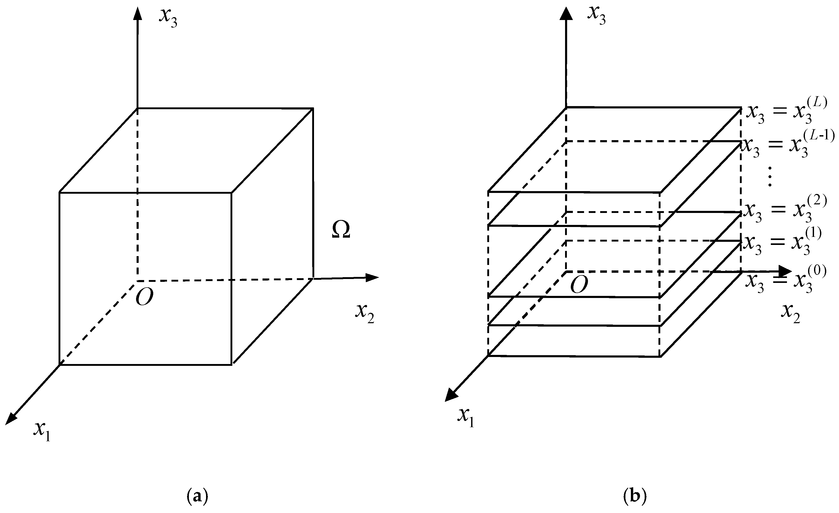
Figure 1. The idea of dimension splitting: (a) the problem domain Ω ; (b) Ω is divided into L + 1 layers.
Mathematics 12 01900 g001
Figure 2. Flow chart of algorithm implementation.
Mathematics 12 01900 g002
Figure 3. Relative error versus node distribution in each subdomain Ω ( k ) .
Mathematics 12 01900 g003
Figure 4. Relative error versus step number L in the dimension splitting direction.
Mathematics 12 01900 g004
Figure 5. Relative error versus d max .
Mathematics 12 01900 g005
Figure 6. Relative error versus α .
Mathematics 12 01900 g006
Figure 7. The numerical and exact solutions in the direction x 1 .
Mathematics 12 01900 g007
Figure 8. The numerical and exact solutions in the direction x 2 .
Mathematics 12 01900 g008
Figure 9. The numerical and exact solutions in the direction x 3 .
Mathematics 12 01900 g009
Figure 10. The numerical and exact solutions in the direction x 1 .
Mathematics 12 01900 g010
Figure 11. The numerical and exact solutions in the direction x 2 .
Mathematics 12 01900 g011
Figure 12. The numerical and exact solutions in the direction x 3 .
Mathematics 12 01900 g012
Figure 13. The numerical and exact solutions in the direction x 1 .
Mathematics 12 01900 g013
Figure 14. The numerical and exact solutions in the direction x 2 .
Mathematics 12 01900 g014
Figure 15. The numerical and exact solutions in the direction x 3 .
Mathematics 12 01900 g015
Figure 16. The numerical and exact solutions in direction r .
Mathematics 12 01900 g016
Figure 17. The numerical and exact solutions in direction θ .
Mathematics 12 01900 g017
Figure 18. The numerical and exact solutions in the direction x 3 .
Mathematics 12 01900 g018
Table 1. Relative errors and CPU time obtained by the HRKPM and RKPM under different node distributions.
Number of NodesRelative ErrorCPU Time (s)
HRKPMRKPMHRKPMRKPM
9 × 9 × 90.00840.0211.6333.59
11 ×11 × 110.0050.01372.8175.79
13 ×13 × 130.00320.00966.92139.69
15 ×15 × 150.00230.00712.21193.5
17 × 17 × 170.00170.005228.56426.42
Table 2. The analytical and numerical solutions were obtained by the HRKPM, RKPM and IEFG methods at different nodes.
(x1, 5/9, 1/2)Analytical SolutionNumerical Solution
HRKPMRKPMIEFG
00.9848077530.9915213710.990448840.993332402
0.0555555560.969846310.9763712180.9773046070.978241394
0.1111111110.9254165780.9316183590.9331034530.933427074
0.1666666670.8528685320.8585556310.8606364970.860251044
0.2222222220.7544065070.7594089230.7619590420.760936722
0.2777777780.6330222220.6371960530.6399368460.638501723
0.3333333330.4924038770.4956338610.4981901360.496666172
0.3888888890.3368240890.3390244520.3410043180.339739671
0.4444444440.1710100720.1721242620.1732050410.172490351
0.56.03 × 10−173.05 × 10−147.47 × 10⁻¹⁴−1.91 × 10⁻¹¹
0.555555556−0.171010072−0.172124262−0.173205041−0.172490351
0.611111111−0.336824089−0.339024452−0.341004318−0.339739671
0.666666667−0.492403877−0.495633861−0.498190136−0.496666172
0.722222222−0.633022222−0.637196053−0.639936846−0.638501723
0.777777778−0.754406507−0.759408923−0.761959042−0.760936722
0.833333333−0.852868532−0.858555631−0.860636497−0.860251044
0.888888889−0.925416578−0.931618359−0.933103453−0.933427074
0.944444444−0.96984631−0.976371218−0.977304607−0.978241394
1−0.984807753−0.991521371−0.99044884−0.993332402
Disclaimer/Publisher’s Note: The statements, opinions and data contained in all publications are solely those of the individual author(s) and contributor(s) and not of MDPI and/or the editor(s). MDPI and/or the editor(s) disclaim responsibility for any injury to people or property resulting from any ideas, methods, instructions or products referred to in the content.