Article

Research on Auxetic Lattice Structure for Impact Absorption in Machines and Mechanisms

by
Levente Széles
1,
Richárd Horváth
2 and
Livija Cveticanin
3,*
1
Doctoral School on Materials Sciences and Technologies, Óbuda University, 1034 Budapest, Hungary
2
Bánki Donát Faculty of Mechanical and Safety Engineering, Óbuda University, 1034 Budapest, Hungary
3
Faculty of Technical Sciences, University of Novi Sad, Trg D. Obratodica 6, 21000 Novi Sad, Serbia
*
Author to whom correspondence should be addressed.
Mathematics 2024, 12(13), 1983; https://doi.org/10.3390/math12131983
Submission received: 6 June 2024 / Revised: 21 June 2024 / Accepted: 24 June 2024 / Published: 27 June 2024

Abstract

:
In this paper, a new type of filled doubly re-entrant auxetic lattice structure for application in damping and energy absorption devices is considered. The structure is modeled to give protection for machines and mechanisms of intensive impact. The suggested structure is the modified version of the auxetic one with silicone fillings. The unit of the structure is assumed as a re-entrant hexagon with four quadrangular absorbers. For the assumed model of unit, the deformation properties and the Poisson’s ratio were computed. The obtained results were experimentally tested. Specimens of filled and unfilled structures were investigated under quasi-static compression. The measured results show that the energy dissipation is more than two times higher for filled structure than for unfilled ones. In the filled structure, the absorber’s rigidity has the crucial role. If the rigidity is small, the absorber, inside the unit, continues to deform from rectangle into rhomboid. Otherwise, if the rigidity is high, units with absorbers form a beam-like structure that buckles and shows high energy absorption effect. The experimentally obtained results are in good agreement with the theoretical ones.

1. Introduction

Mechanisms and machine parts that work with impact, in addition to the standard requirements, are subject to requirements for increased strength, wear resistance and hardness of parts, as well as for impact energy absorption, noise and vibration reduction, etc. [1,2]. Honeycomb and lattice structures are found to be the best answer to the aforementioned demands [3,4]. The artificial porous periodical structures with light weight [5], called ‘elastic metastructures’, due to their energy absorption properties [6,7] and noise and vibration suppression [8], are appropriate to be applied in many industries including the automotive [9,10], aerospace [11], and military [12] ones, as well as in the sports equipment industry [13]. The utilized structures are manly produced by 3D printing [14]. To improve the structure, two main directions are evident: one to improve the structure material, and the second to reconstruct the geometry of the structure.
Based on the rule for buildings materials about their dependence of properties on material combination [15,16,17,18], the material combination method is developed for the metastructure production. Additional materials are mixed into the base material for printing [19,20]. The fiber-reinforced parts have undeniably better mechanical properties, but there remain the problems of anisotropy, porosity, and delamination, which have a negative impact on product use.
As an improvement, the combining metastructures are developed, inspired by the structure of the human tooth [21]. The conventional honeycomb lattice structure is combined of two materials. The lattices are printed with a hard material along the outside and inside of their perimeter, while the center of the perimeter is printed with a soft material. By varying the thickness ratio of the rigid and flexible regions, the mechanical properties of the structure (energy absorption and damping characteristics) can be tuned [22,23,24,25]. A wide spectrum of lightweight materials is used for filling lattices and other structures, such as polyurethane foams [26,27], syntactic foams [28], metallic foams [29,30], and agar gel [31]. Prajapati et al. [32,33] have created a 3D-printed hard outer layer specimen filled with soft polyurethane foam, giving the material significantly improved impact and fracture properties. Chapkin et al. [34] printed titanium alloy lattice specimens which were filled with compressible and non-compressible elastomers. Black et al. [31] have filled simple cubic lattices with agar gel. It was found that comparing to the unfilled control group, the lattices filled with gel demonstrated a 50% increase in the energy absorbed and a 55% increase in the displacement to failure. Their work perfectly illustrates that filling is relevant even in the case of simple geometries and manufacturing technologies.
The previously presented multi-material-based structures achieved more favorable energy-absorbing and vibration-damping capabilities than the one-material structures. However, to successfully merge certain properties of multiple materials, proper bonding is inevitable. Multi-material structures generally may fail at interfaces; the proper interface bond must be as strong as the strength of the weaker material. Otherwise, the structure is failed at lower stress, making the combination disadvantageous [35,36]. However, the main disadvantage of the previous structures is that the vibration and noise suppression is only for a certain frequency domain [37,38,39,40].
An improvement can be created by topologically optimal geometries of different materials (see [41,42]). In addition, to overcome the problem, the auxetic structures are introduced [43,44]. Namely, the energy absorption property of this structure is constant and independent of the ratio of the frequency of the external force and the structure’s eigen-frequency. The suggested system is also a kind of lattice structure, with the elementary constitutive units having the negative Poisson’s coefficient. This units are hexagonal.
Recently, the units are rearranged with the aim to improve the mechanical properties [45]. A novel doubly re-entrant auxetic honeycomb structure was introduced [46]. In this paper, a rearranged doubly re-entrant auxetic structure partially filled with a soft absorber material is considered. The aim of the research is to obtain the influence of the coupled combination of the basic structure and filling absorbers on the specific energy absorption. The investigation is done theoretically and experimentally. The result is that the structure with optimal energy absorption is obtained and suggested for application in devices for impact protection in machines and mechanisms.
The paper is divided into 4 sections. After the Introduction, in Section 2, the novel doubly re-entrant auxetic unit cell with and without filling is theoretically investigated. The deformation properties and conditions for auxetic behavior are considered. The absorber displacement and its deformation in the cell due to compression is determined. In addition, the buckling conditions in the structure are obtained. In Section 3, the fabrication of test specimens is presented. The force-displacement and absorbed energy-displacement curves are determined for the unfilled and filled structures with various geometric properties. An explanation of specific absorption energy based on the experimental and theoretical consideration is presented. The unfilled and filled specimens with various rigidity property are compared. The structure with the best energy absorption property is suggested. The result is proved by applying of the statistical T-method. The paper ends with Conclusions.

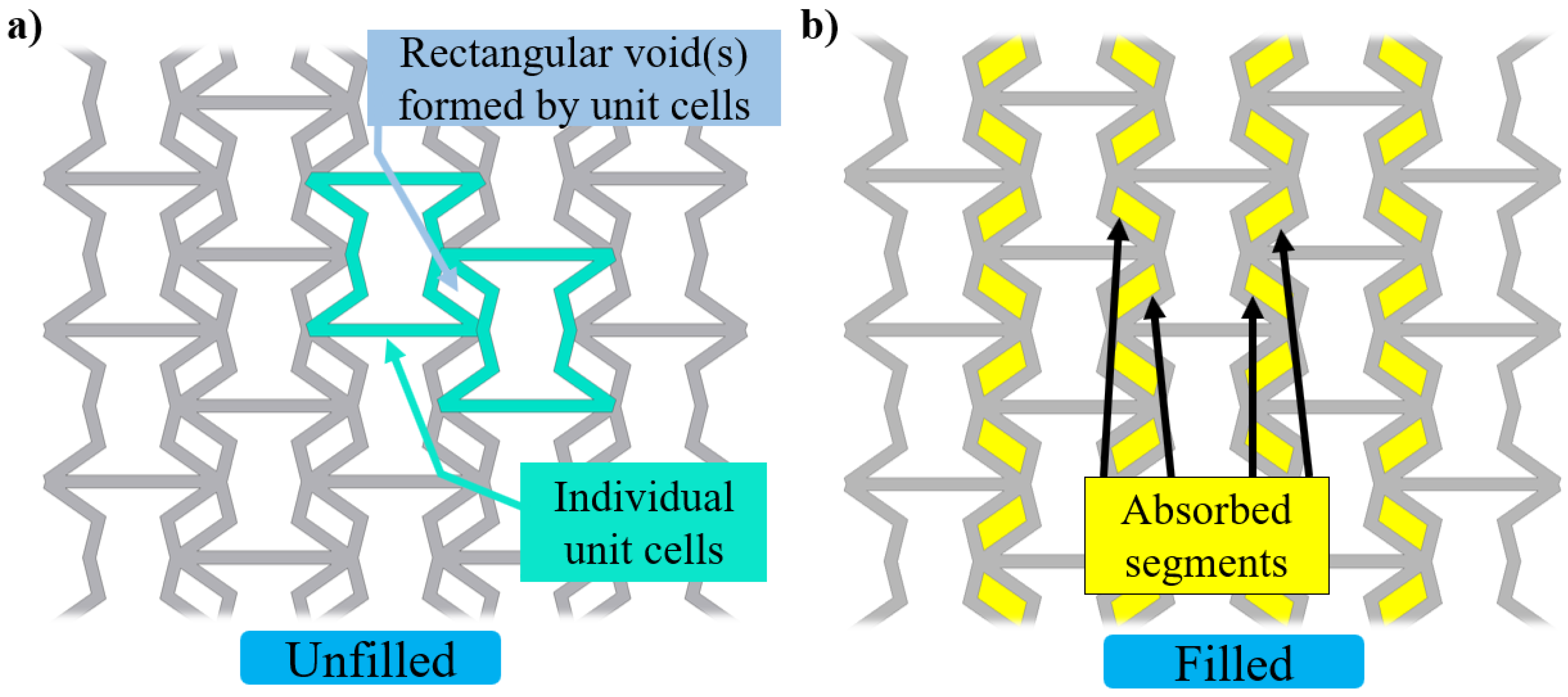
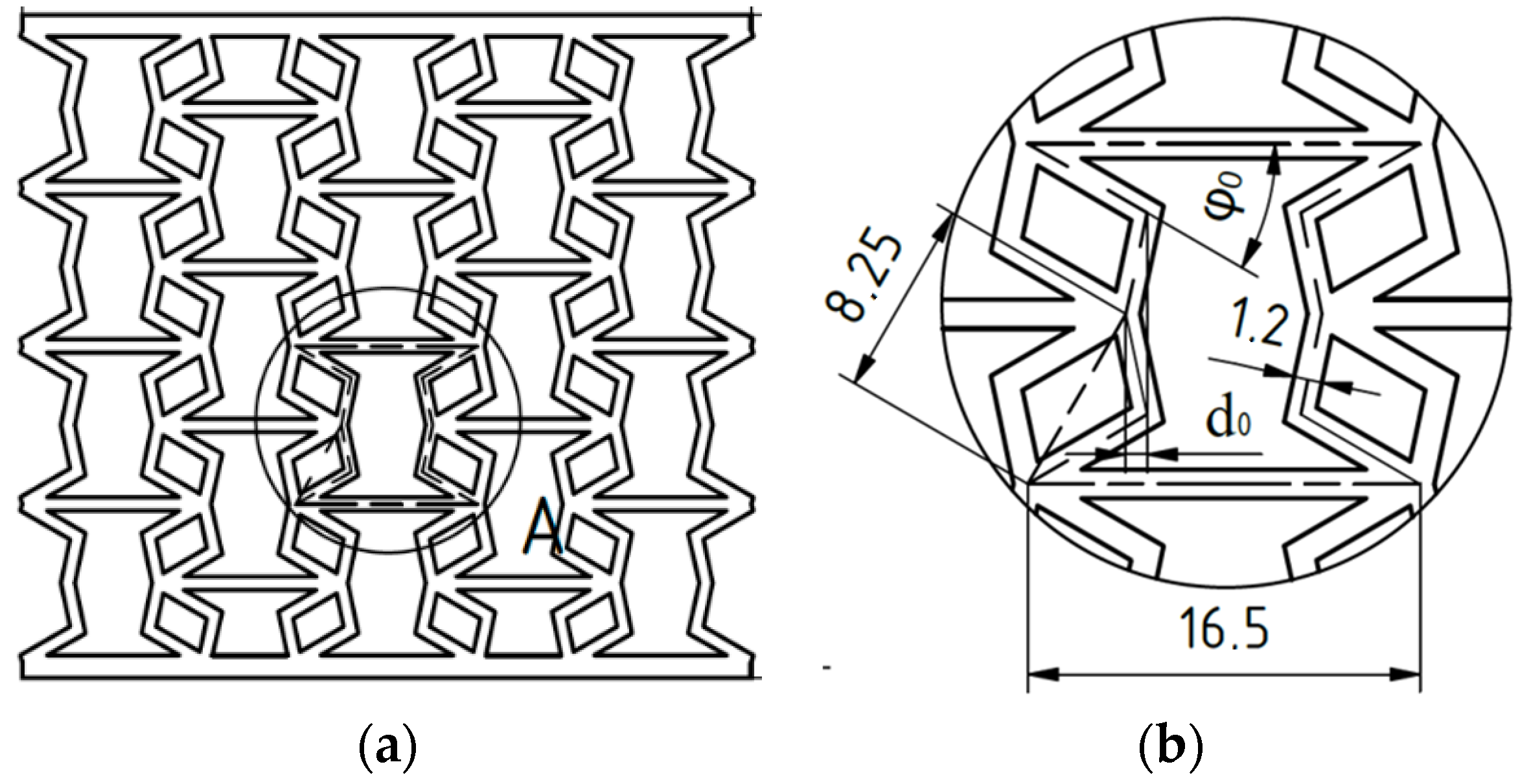
2. Models of Filled and Unfilled Structures

In Figure 1, the unfilled (Figure 1a) and partially filled (Figure 1b) doubly re-entrant honeycomb structures are shown. Namely, in the quadrilateral voids formed by neighboring unit cells, the filling, which represents the absorber, is settled. The aim of the section is to compare the deformation properties of the filled and unfilled structures. For this reason, independent parameters, which are related to the deformation i.e., shape and dimension variation, have to be introduced. These parameters are of geometrical type.
For structure analysis, the unit cell with four absorbers is separated (Figure 2). The constant unit cell dimensions are the width L, thickness t and out-of-plane thickness b, and for the absorber the dimensions are the length h and width w. Due to force action, the unit cell deforms and the inner width L1 and the high H of the unit are varying.
The dimensions variation is assumed as a function of two independent values: the angle φ between the horizontal and upper re-entrant edges (called deg) and the distance between the breakpoints d (called offset). Then, it is calculated as
H = 2 h s i n φ + 2 w 2 d 2 ,           L 1 = L 2 h c o s φ + 2 d .
However, the geometric constraint of the unit is
L 2 h c o s φ 0 .
In this section, the deformation properties of the filled structure are modelled. Two types of models are introduced: one with soft filling, and a second where the absorber is an almost rigid body.

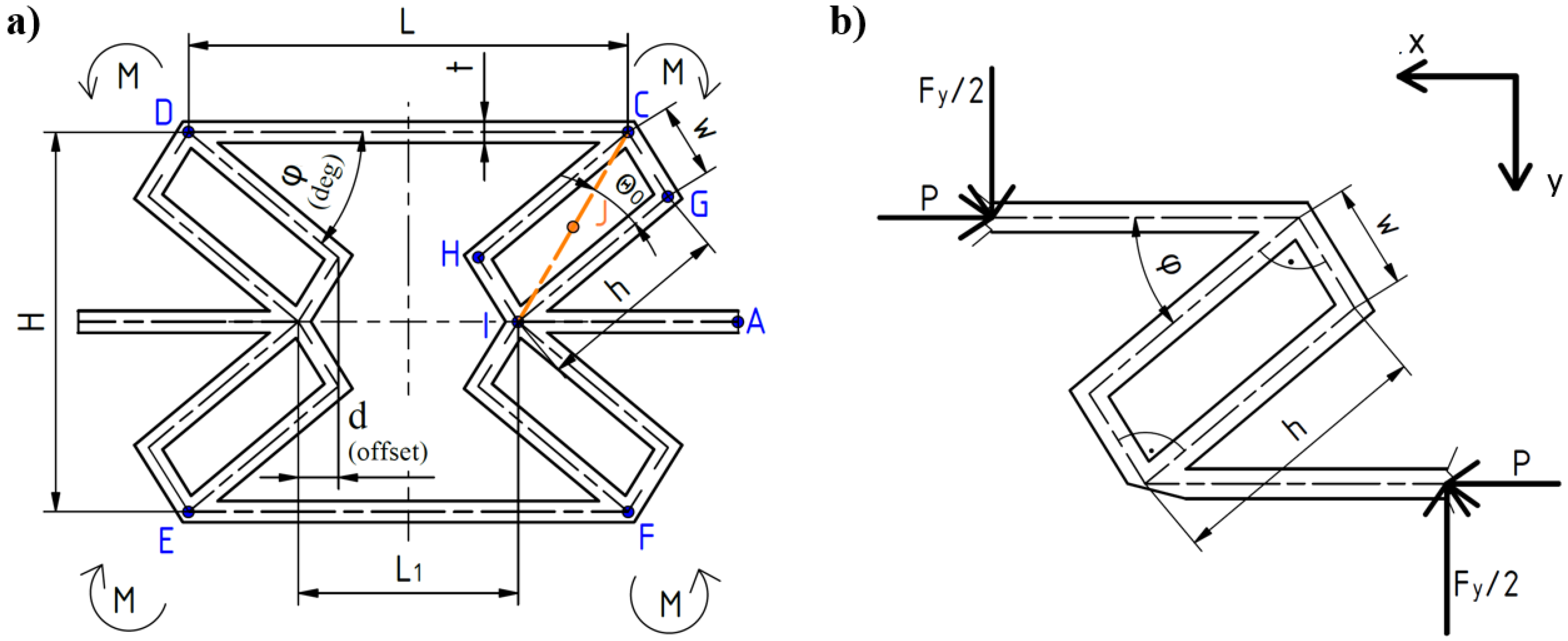
2.1. Auxetic Deformation of the Structure

For far field stress in y-direction, the unit with four absorbers (Figure 2a) is loaded with the force Fy. Due to symmetry, let us analyze the upper quarter segment of the unit (Figure 2b). The cross-section Ab and the Young’s modulus of elasticity of material Eb of the basic unit are constant. The elasticity of absorber material is Ea. For simplicity, it is assumed that the absorber is rectangular, with constant cross section Aa. In addition, it is supposed that the absorber dimensions satisfy the relation w << h. The segment of the unit (Figure 2b) is in equilibrium if the external moment is balanced with the moment of forces F y 2 . For computational reasons, in the segment, two opposite virtual forces P in x direction are introduced. The forces F y 2 and P cause axial and bending deformation. The total strain energy for the unit-absorber section is the sum of bending and compression energies and is as follows:
U = 1 2 E b A b 0 L / 2 P 2 d s + ( 1 2 E b A b + 1 2 E a A a ) 0 h ( F y 2 s i n φ P c o s φ ) 2 d s + 1 2 E b A b   0 w ( F y 2 c o s φ P s i n φ ) 2 d s + 1 2 E b I b 0 L 2 ( F y 2 s ) 2 d s + ( 1 2 E b I b + 1 2 E a I a ) 0 h ( F y 2 L 2 s c o s φ P s s i n φ ) 2 d s + 1 2 E b I b 0 h ( F y 2 L 2 h c o s φ + s s i n φ P ( h s i n φ + s c o s φ ) ) 2 d s
where
A a = w b ,           I a = b w 3 12 ,           A b = t b ,     I b = t b 3 12 .      
According to the Castigliano theorem, the displacement u in x direction and v in y direction are derived as
u = ( U P ) P = 0 = ( F y 2 ) ( 1 E b A b + 1 E a A a h 2 sin 2 φ w 2 E b A b sin 2 φ + 1 E b I b + 1 E a I a h 2 s i n φ L 2 2 h 3 c o s φ + 1 E b I b L 2 h c o s φ h w s i n φ + h w 2 2 s i n 2 φ + w 2 2 L 2 h c o s φ c o s φ + w 3 6 sin 2 φ ) ,
v = U ( F y / 2 ) P = 0 = ( F y 2 ) ( 1 E b A b + 1 E a A a h s i n 2 φ + w E b A b c o s 2 φ + 1 3 E b I b ( L 2 ) 3 + 1 E b I b + 1 E a I a ( L 2 h L 2 h c o s φ + h 3 3 c o s 2 φ ) + 1 E b I b ( w L 2 h c o s φ 2 + w 2 L 2 h c o s φ s i n φ + w 3 3 s i n 2 φ ) .
Analyzing (5) and (6), it is obtained that for the constraint (2), the displacement (5) in the x direction is negative, while in y direction (6) it is opposite, i.e., positive.
In the relations (1), the angle φ is varying in the interval φ ϵ 0 , φ 0 ,   where φ 0 is the initial deg angle. For φ = φ 0 , according to (1), the initial inner width and initial height of the segment is as follows:
L 1 / 2 = L 2 h c o s φ 0 + 2 d 0 ,           H / 2 = h s i n φ 0 + w 2 + d 0 2
where d 0 is the initial offset dimension. Comparing the displacements (5) and (6) with the initial inner width and height (7), the strains in x and y direction are as follows:
ε x = u L 2 h c o s φ 0 + 2 d 0   ,                       ε y = v h s i n φ 0 + 2 w 2 + d 0 2 .
Thus, based on (5), (6), and (8), the sign of the Poisson’s ratio ν = ε y ε x is negative. It proves that the filled structure is auxetic.
Analyzing relations (5) and (6), it is obvious that the value of the displacement is higher for the filled structure than for the unfilled one. The effect of absorber depends on the elasticity of the filling: The smaller the Young’s modulus of elasticity Ea, the higher the terms with E a A a and E a I a .
For φ = 0, the displacements (5) and (6) are
u = ( F y w 2 w 2 E b I b ) L 2 h ,         v = ( F y 2 1 E b A b ) w
and the corresponding inner width and high (1) are
L 1 = 2 ( L 2 h ) ,         H = 2 w
when for the rectangular absorber, d = w sin 0° = 0. The segment is deformed into a simple rectangle with width h in x-direction and height w in y-direction (Figure 3a). In addition, the units form a beam-like structure along the y-axis (Figure 3b). The length l of the beam depends on the number n of structure’s units, i.e., l = n (2w). The beam of units has a periodical variable rigidity EI. For simplification, the rigidity of the absorber EaIa, is assumed to be the dominant one.
Deformation of the aforementioned unit and of the beam structure depend on the axial force Fy and its corresponding moment M.

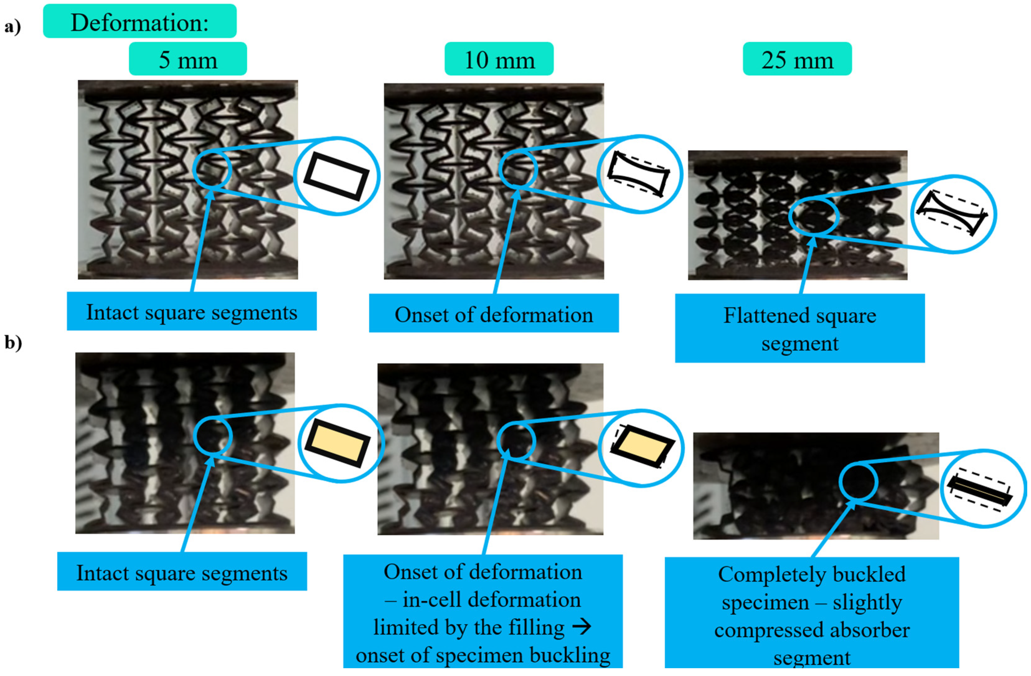
2.2. Shape Variation of the Absorber Unit and Buckling of the Beam-Like Structure

Due to action of the axial force Fy, deformation of the rectangle shape into rhomboid one occurs (Figure 3a). Theoretically, the limit deformation is up to one line. In addition, the moment M, which is the result of the force Fy, causes bending of the beam-like structure (Figure 3b). The maximal deflection of the beam, caused by moment M, is
x m a x = 3 M ( 2 n w ) 2 27 E a I a , .
The higher the number of units in y-direction and the softer the absorber material Ea, the higher the deformation.
Finally, the buckling of the beam-line structure occurs if the force that acts has the critical value Fcr:
F c r = π 2 E a I a L e 2
where Le is the effective length of the beam, which depends on the boundary conditions of the beam. In the suggested model, the beam is pin–pin supported and has the effective length Le = 2nw. The critical force is
F c r = π 2 E a I a ( 2 n w ) 2 .
The displacement due to buckling is affected by several factors, including the material properties, cross-sectional shape, and dimensions, but also the loading conditions. These factors determine the critical load (13) at which buckling occurs and the resulting displacement. However, the structure, in buckling, becomes unstable, and to model what happens after buckling requires a nonlinear analysis.
REMARK: The critical force (12) depends on the boundary conditions and the value of Le. If the beam is fixed–free supported, the critical force is four times smaller than (13), as Le = 4nw. If the beam is fixed–pin or fixed–fixed supported, the critical force is two times and even four times higher than (13) as Le = (nw)/ 2 and Le = (nw), respectively.

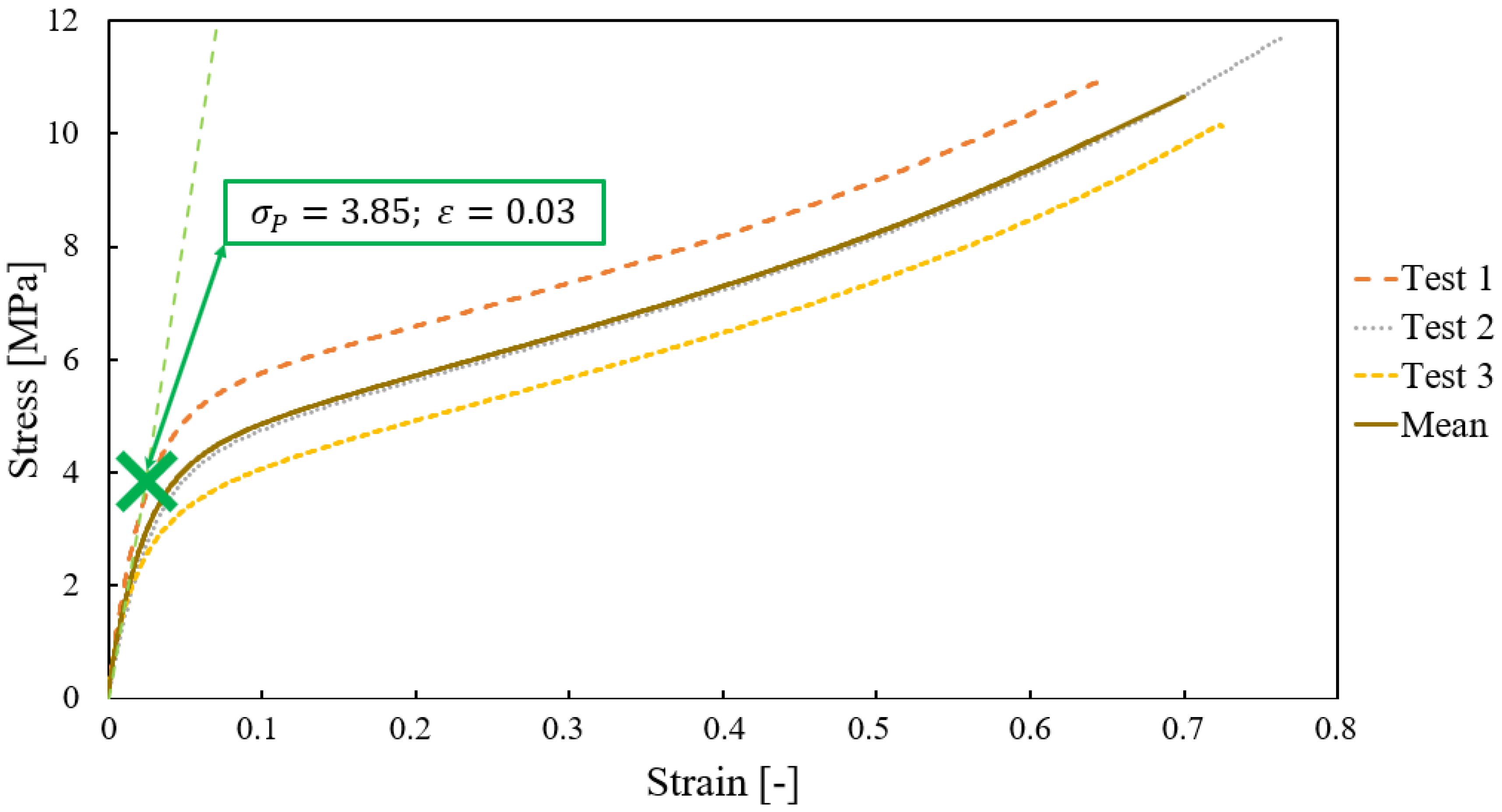
3. Experimental Research and Results

The deformation of the filled and unfilled structures was experimentally tested. The specimens were printed on an Anycubic Photon M3 printer via masked stratigraphy, which is a form of Masked Stereolithography Apparatus (MSLA) additive manufacturing technology. The free spaces in the honeycomb were manually filled with silicone. The overall dimensions of samples are shown in Figure 4. Two-unit cell parameters were varied: deg φ 0 and offset d 0 . Deg had the values of 30, 35 and 40 degrees, while offset was 0.9 mm, 1.5 mm and 2.1 mm. In total, 18 specimens (9 unfilled and 9 filled) were considered.
The parameter combinations for specimens are shown in the Table 1.
The printing material was a unique resin mixture with high flexibility and firm properties. The resin mixture contained 75% Litliq FX60 Flexible rubber-like and 25% Litliq TH50 Tough resins. The printing parameters were as follows. The layer exposure time for 0.05 mm layer thickness was 4 s with 2 s wait time (off-time) between layers, enabling the high viscosity resin evenly to spread in the resin tank. Each specimen was printed at a 14-degree angle relative to the build platform. Specimens were washed for 3 min in 99.8% purity isopropyl alcohol, and then UV cured for 15 min. Anycubic Wash & Cure 2.0 25W resin curing machine was used. Specimens were filled with Soudal Polysiloxane based Trade sanitary silicone (silicone). We chose silicone for filling as is found to have substantially high impact resistance, good dimensional stability, and stability of physical and mechanical properties (does not end up losing the elasticity and has high load-bearing properties in compression and tension). Silicone is not chemically reactive and has excellent adhesion to smooth surfaces.
For the filling procedure, syringes with special tips were designed and manufactured (Figure 5). The tips have holes of the same form and size as the regions to be filled in specimens, allowing for homogeneous filling. The syringes were filled with silicone and then de-aerated. Specimens were filled under pressure, ensuring complete and homogeneous filling. Once the silicone cured, the excess was trimmed.
Tensile testing of the structure was carried out according to EN ISO 527-2 [47], using a Zwick Z020 type tensile testing machine (Ulm, Germany) with a measuring limit of 20 kN. The measured stress–strain values are plotted in Figure 6. The stress–strain diagram shows that the relation is linear only for a small deformation range. The mean modulus of elasticity for the material is E = 128.3   M P a and the stress is σ p = 0.03   M P a . At the other side, the modulus of elasticity of the Trade sanitary silicone, used for filling, is much lower (0.4 MPa [32]).

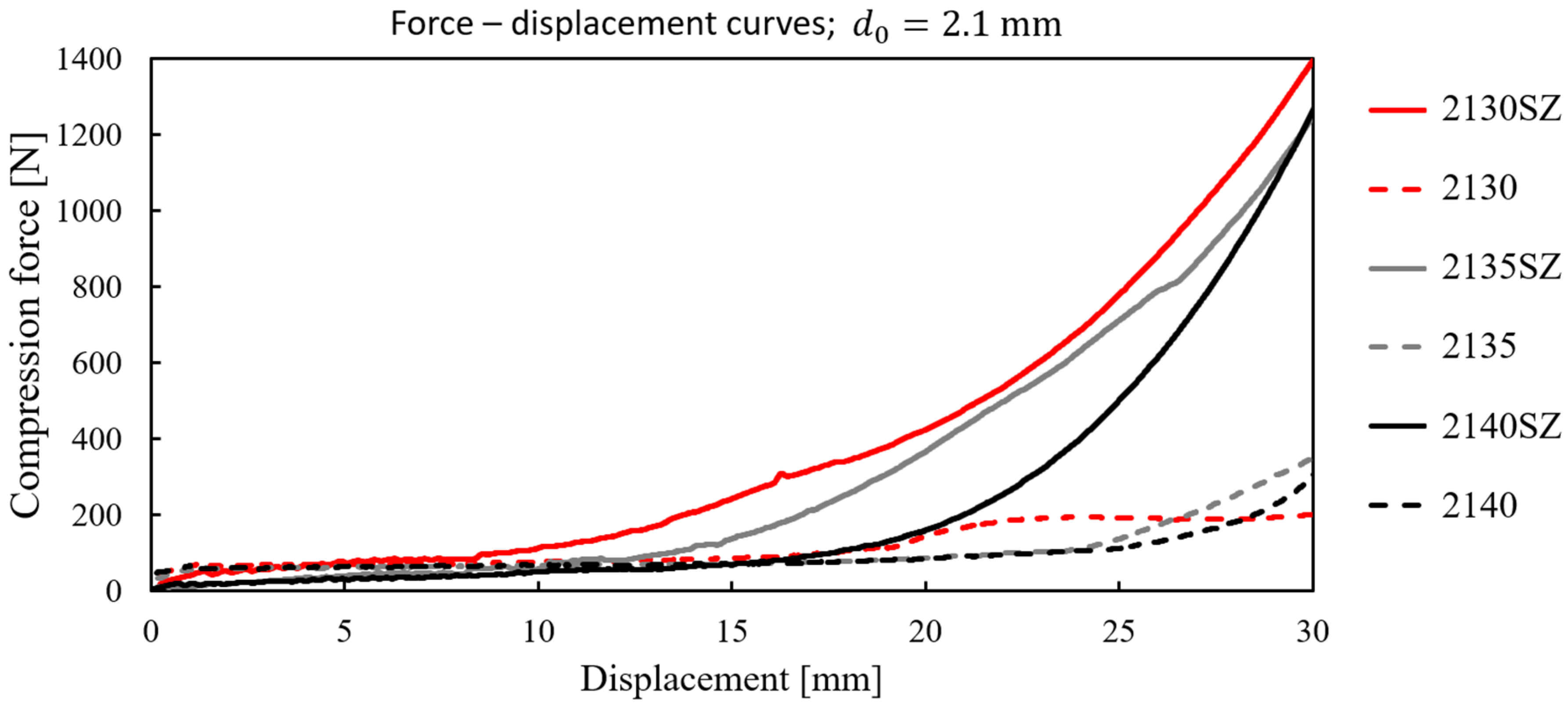
3.1. Testing of Specimens on Compression: Force-Displacement Curves

Measuring on filled and unfilled specimens with offset d 0 = 0.9   m m , d 0 = 1.5   m m and d 0 = 2.1   m m , and deg angles φ 0 = 30°, 40°, and 45° were done. During research, each specimen was subjected to compression testing at low speed of 5 mm/min, up to 30 mm/min on a Hegewald & Peschke 40-ton capacity machine.
In Figure 7, Figure 8 and Figure 9, the force–displacement diagrams are plotted. Analyzing the plots, it is evident that for small deformations, the force-displacement diagrams are almost linear for all filled and unfilled specimens. It agrees with the theoretical result (6). The diagram of the force–displacement relation is nonlinear only for higher values of displacements.
In Figure 7, Figure 8 and Figure 9, the force–displacement curves for filled specimens with corresponding unfilled ones are compared. It is obtained that the curve for filled specimen is above the corresponding unfilled one. Thus, the diagram for 0930SZ ( d 0 = 0.9   m m , φ 0 = 30°, filled) is higher than the diagram for 0930 ( d 0 = 0.9   m m , φ 0 = 30°, unfilled) in Figure 6. This conclusion is valid for all filled specimens in comparison to corresponding unfilled ones. However, the difference between filled and unfilled samples is smaller for small displacements and lower offset values.
For specimens with an equal value of the initial offset, the increase in the force versus displacement curve is higher for a smaller initial deg angle. Thus, for d 0 = 0.9   m m , the force–displacement diagram of 0930SZ with φ 0 = 30° is above 0940SZ with φ 0 = 40° and 0945SZ with φ 0 = 45° (see Figure 7). The same conclusion is evident for specimens with d 0 = 1.5   m m (Figure 8) and d 0 = 2.1   m m (Figure 9).
In addition, in the samples with the same deg angle, the force is higher if the offset value is higher (see Figure 7, Figure 8 and Figure 9). Comparing the force-displacement diagrams for different offset values (see in Figure 7, Figure 8 and Figure 9, offset values 0.9 mm, 1.5 mm, and 2.1 mm) and a constant deg (for example 30 deg), it is obtained that the force increase is faster, and the maximum compressive force is higher for higher values of offset than for smaller ones. Thus, the force increase is the fastest for 2140SZ and the slowest for 0930SZ. For the same displacement and deg angle, the force in the sample is higher for offset d 0 = 2.1   m m than for 1.5 mm and 0.9 mm. Finally, the best force-deflection property is evident for 2130SZ.

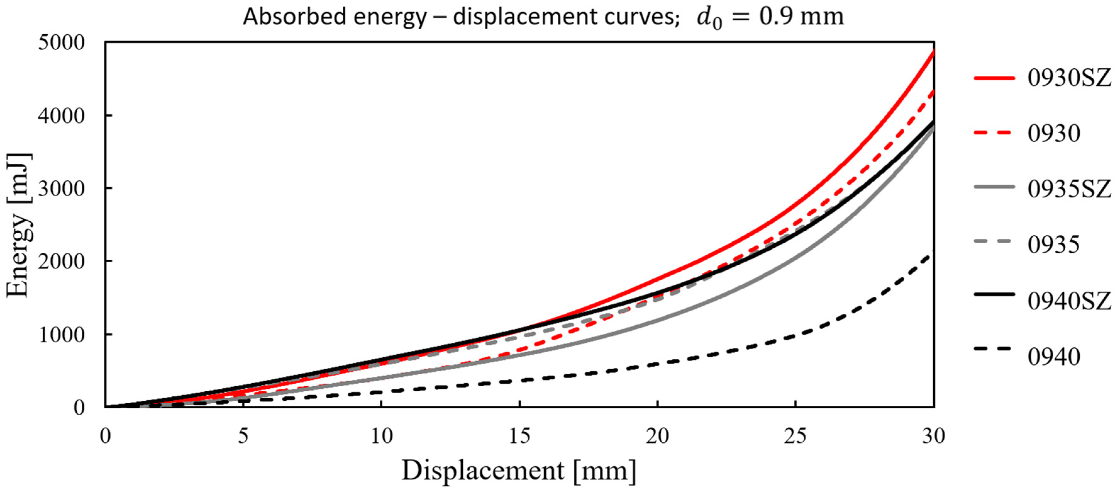
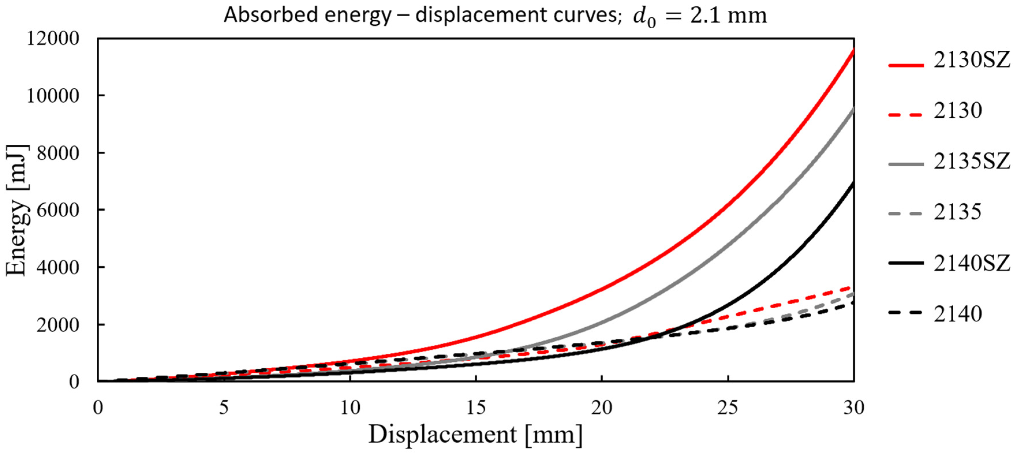
3.2. Absorbed Energy-Displacement Curves

Using the force–displacement expression, the absorbed energy ( I ) is computed. The absorbed energy corresponds to the area under the experimentally recorded force–displacement curve and is given by:
I = 0 v m a x F v d v
where F(v) is the force distribution function, v is the displacement, and vmax is the maximal displacement. In Figure 10, Figure 11 and Figure 12, the absorbed energy–displacement diagrams for filled and unfilled structures with offset values d 0 = 0.9   m m , d 0 = 1.5   m m , and d 0 = 2.1   m m and deg angles φ 0 = 30°, 40°, and 45° are plotted. Comparing these curves with those in Figure 7, Figure 8 and Figure 9, the qualitative similarity is seen. Thus, the comments regarding the force–displacement curves apply to the absorbed energy–displacement curves, too.

3.3. Specific Absorbed Energy

As the filled and unfilled specimens differ in weight, for comparison of the energy absorption, the specific absorbed energy parameter [47] is introduced. Namely, dividing I with the mass m   of the specimen, the specific absorbed energy follows as
I s = I m .
The values of specific absorbed energy for all specimens are compared. The results of these calculations are presented in Figure 13.
It is obtained that the I s values for specimens 2130SZ, 2135SZ, 2140SZ, 1540SZ, 1530SZ and 0940SZ, which are filled with silicon, are higher compared to the corresponding 2130, 2135, 2140, 1540, 1530, and 0940 unfilled ones. However, the addition of the silicon absorbers results in a lower I s value for 0930SZ, 0935SZ, and 1535SZ than for the corresponding 0930, 0935, and 1535 unfilled ones. Overall, it can be stated that filling the specimens increased the absorbed energy amount.
The best results are obtained for specimens with offset values of 2.1 mm for all deg parameter values. For the filled 2130SZ lattice, the I s is 159 mJ/g and it is evident that the energy absorption is 2.5 times higher than in the unfilled one. In the filled sample 2135SZ, the I s value is 137 mJ/g, and is 2.4 times higher compared to the unfilled specimen. The unfilled lattice 1530 has I s of 60 mJ/g, which is half that of its silicon-filled pair.
Finally, it is seen that the geometric parameters such as the offset value and deg parameter have influence on the energy absorption. The deg parameter affects the specimen’s energy absorption capability. The energy absorption capability increases with increasing the deg value: for 30 degrees, it is 1.7; for 40 degrees, it is 1.2; and for 45 degrees, it is 1.7. In addition, with increase of the offset value, the average absorbed energy ratio increases, too. Thus, for offset of 0.9, the average absorbed energy ratio is 1; for 1.5 mm, it is 1.3; and for 2.1 mm, it is 2.4.
Comparing specimens with the same deg parameter but with different offset values, the following statements can be made. The fastest increase of I s   with an increase of the offset value is for filled specimens with initial deg angle of 30°. The same tendency of increase of I s   with an increase of offset is observed for filled specimens with deg values of 35 and 40. The increase velocity of I s is greater for the smaller initial deg parameter specimens. These phenomena may be explained using the following theoretical consideration. Namely, according to Figure 2b, the length of the filling l f   orthogonal to compression force is approximately
l f h c o s φ + d .
For constant deg, but higher deformation, i.e., higher offset d, the value of l f is also higher and gives the larger absorption region of the filling. On the contrary, for the fixed offset d, the first term of the relation (16) is higher for smaller deg angle. Thus, the smaller is deg the l f is longer, causing the absorption region and the velocity of absorption of the filling to increase.

3.4. Explanation of Energy Absorption

Compressed specimens exhibited either buckling or continuous auxetic deformation behavior. Due to loading, most of the unfilled specimens exhibit in-cell deformation. Deformation is unrestricted and no significant increase of energy absorption until compaction (around 20 mm deformation) is evident.
At the other side, at small deformations, the filled rectangular segments restrict in-cell deformation, resulting in buckling. As the deformation progresses, the absorber segments are progressively loaded and progressively increase the compressive resistance as well as the amount of the absorbed energy. Overall, the absorber segments, at first, allow great displacement at low compressive resistance, and then progressively become stiffer.
In Table 2. the experimentally observed deformation behaviors as the function of geometrical parameters i.e., offset and deg values, for filled and unfilled structures, are presented. In Table 2, it is shown that in unfilled structures 0930, 0940, 0945, and 1530, buckling occurs under influence of compression force, while the other unfilled structures, 1540, 1545, 2130, 2140, and 2145, show continuous auxetic deformation. The filled specimens 0930SZ, 0940SZ, 0945SZ, 1530SZ, 1540SZ, 1545SZ, and 2130SZ buckle during compression, while the 2140SZ and 2145SZ specimens exhibit continuous auxetic deformation.
To explain the effect of filling on deformation properties of the specimens, let us consider the two of them: 1540 and 1540SZ (Figure 14). Comparing the compression behavior of 1540 and 1540SZ, it is obvious that the unfilled sample exhibits continual auxetic deformation while the filled one exhibits buckling.
During compression, the 1540 specimen deforms—the voids are compacted and the edges come into contact with each other and basically eliminate the quadrangular segment (Figure 14a). During compression, the unfilled specimen 1540 deforms in an unrestricted manner, and no significant increase in absorbed energy for the specimen is evident.
On the other hand, in the filled sample 1540SZ (Figure 14b), the absorber segments are progressively loaded. First, the absorber shape variation occurs: The rectangle becomes a rhomboid. However, due to compressive resistance, the displacement of absorbers as rigid bodies occurs. The specimen become stiffer and, consequently, the deformation in the regions of absorbers is impossible. When the force reaches the critical value, the buckling of the specimen occurs (see Figure 14). The same result was previously proved mathematically in Section 2.
Namely, the compression force in the unfilled sample causes extensive deformation. The absorbed energy is used for the deformation of the auxetic structure according to expression (8). In the filled sample, the external energy is partly used for the motion of the units and partly applied for the deformation of structure. The rectangle units change their forms into rhomboids, and for the critical value of the force, the buckling of the beam-like structure occurs.

3.5. Statistical Indication of Significance of Deg and Offset Parameters

In this section, the main effect plots are shown for determination of the significance of parameters of structure on the force, specific force, absorbed energy, and specific absorbed energy. In Figure 15, the measured values as a function of the geometric parameters deg and offset for the displacement interval up to 30 mm are plotted.
It is obtained that there is a significantly increase of compression force and specific compression force in filled structure when the offset parameter is increased (Figure 15a,b). The deg parameter has no significant effect on these properties. Filling has a similar effect on absorbed and specific absorbed energy (Figure 15c,d). Increasing the offset parameter leads to a large increase in absorbed and specific absorbed energy, while increasing the deg parameters lead to a decrease. In case of the unfilled specimens, geometric parameters have considerably less effect on the measured physical properties; they only affect the deformation behavior, i.e., the auxeticity.
Based on the aforementioned analysis, it is evident that the energy absorption capability varies significantly with changes in geometry and rigidity, indicating a need for precise control over these factors. The accuracy of controlling the geometry and rigidity of the proposed design is evaluated with the adequate printing of specimen. Namely, specimen accuracy is ensured by the applied additive manufacturing technology (MSLA) and the 3D printer itself, which has a 40-micron resolution. The mentioned print resolution gives a high accuracy in geometry and does not allow deviation. On the other hand, the base material is a unique resin mixture with constant rigidity. The control of rigidity of specimen is also connected with the printing parameters and the post-process ones.

4. Conclusions

In this paper, the novel doubly re-entrant auxetic honeycomb structure partially filled with a soft absorbed material is considered. For experimental reasons, specimens based on the novel doubly re-entrant auxetic unit cell were additively manufactured by 3D printing and filled with silicon. The specimens were tested under quasi-static compression. Based on our investigation, the following conclusions can be drawn:
  • Specimens exhibit two significantly different deformation behaviors: buckling and continuous auxetic (preferred). Filling has a negative effect on the deformation behavior: During deformation, the silicone filled voids limit the in-cell deformation (for d 0 = 0.9–1.5 mm) and this results in specimen buckling. However, for higher offset values ( d 0 = 2.1   m m ), compaction occurs more even throughout the geometry; thus, buckling will not occur even with filled structure.
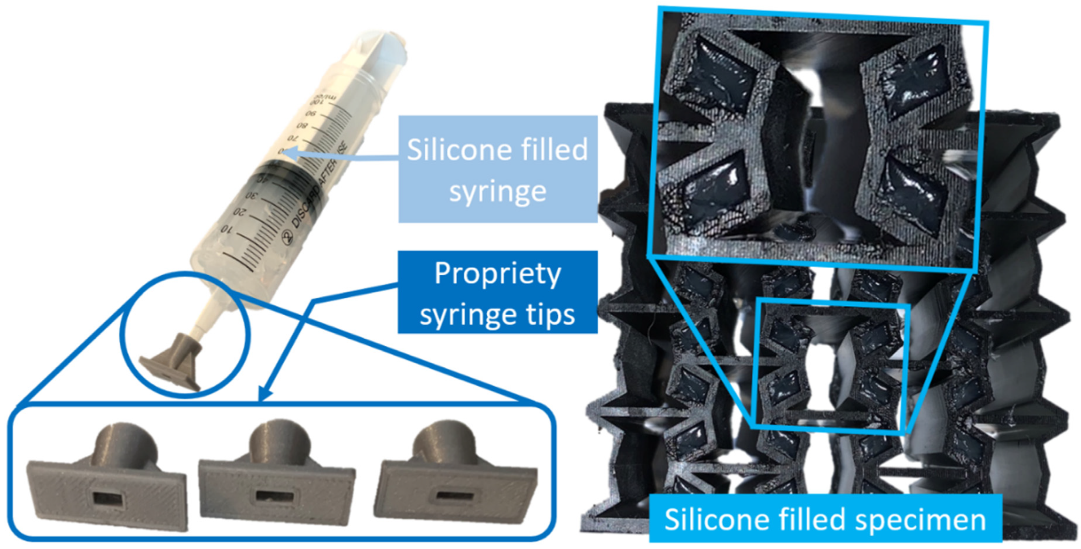
  • Owing to the silicon filling, a new structure applicable for energy dissipation is obtained. The coupled combination aims to significantly improve the energy absorption capacity and to achieve a deformation-induced hardening characteristic. Compared to the unfilled control group, it was found that the filled structure demonstrates an increase in energy absorption. Silicone filled specimens can absorb up to 2.5 times more energy. The energy absorption depends on the geometry and rigidity of the structure.
  • The filled structure increases the rigidity of the specimens with the increase in the offset value. The absorbed energy ratio between filled and unfilled structures increases with the increase in the offset value. Thus, for offset of 0.9, the average absorbed energy ratio is 1; for 1.5 mm, it is 1.3; and for 2.1 mm, it is 2.4.
  • The deg parameter, used to characterize the geometrical modification, effects the specimen’s energy absorption capability. The energy absorption capability decreases with a decreasing deg value. The ratio of energy absorption of filled to unfilled specimens varies with the angle value: for 30 degrees, it is 1.7; for 40 degrees, it is 1.2; and for 45 degrees, it is 1.7.
  • Based on the research, it is concluded that the filled specimen 2130SZ has the best energy absorption property. The complex behavioral mechanism of the 2130SZ specimen is very beneficial for impact protection. At the beginning of the impact process, the structure absorbs the energy with great deformation and slows down the displacement. After that, the impact energy is intensively absorbed. By achieving a deformation-induced hardening characteristic, the collision energy can be sufficiently absorbed. It makes the structure beneficially applicable for the protection against impact. However, certain applications may require easier compressibility and smaller energy absorption. Then, the specimens may have other properties that can be considered as optimal for that specific application.
  • Finally, the aforementioned researched filled structure is recommended to be applied in energy absorbing and damping devices in machines and mechanisms.

Author Contributions

Conceptualization, L.C.; Methodology, L.C.; Validation, L.S.; Formal analysis, R.H.; Investigation, L.S.; Writing—original draft, L.C.; Visualization, L.S.; Supervision, R.H. All authors have read and agreed to the published version of the manuscript.

Funding

This research was funded by the ÚNKP-23-3 New National Excellence Program of the Ministry for Culture and Innovation from the source of the National Research, Development and Innovation Fund.

Data Availability Statement

The original contributions presented in the study are included in the article, further inquiries can be directed to the corresponding author.

Conflicts of Interest

The authors declare no conflict of interest.

Nomenclature

A a , A b [ m m 2 ]Cross section of absorber and of basic unit, respectively
b ,   t [mm]Thickness and width of the unit cell structure
d [mm]Offset value of the until cell
E a , E b [MPa]Modulus of elasticity of absorber and basic unit, respectively
F x [−]Force–displacement function
F c r [N]Critical buckling force
F y [N]Force in y direction
H , L , L 1 [mm]Height, width, and inner width of the unit cell, respectively
h , w [mm]Height and width of the absorber segment, respectively
I a ,   I b [ m m 4 ]Moment of inertia of the absorber and basic unit
I [mJ]Absorbed energy
I s [mJ/g]Specific absorbed energy
l [mm]Total heigh of the beam-line series of absorbers
m [g]Mass of a specimen
M [Nm]Moment between unit cells
P [N]Virtual force
U [J]Total strain energy
u , v [mm]Displacement in x and y direction
x m a x , y m a x [mm]Maximal deflection in x and y direction
ε x , ε y [−]Average strain in x and y direction, respectively
ν [−]Effective Poisson’s ratio of the unit cell
σ x , σ y [MPa]Far field stress in the x and y direction
φ   [ ° ]deg angle value of the unit cell

References

  1. Jafari, M.H.A.; Zarastvand, M.R.; Zhou, J. Doubly curved truss core composite shell system for broadband diffuse acoustic insulation. J. Vib. Control 2023, 2023, 17. [Google Scholar] [CrossRef]
  2. Nema, V.; Jakab, A.; Molnar, J.; Szabo, B.; Szoke-Trenyik, E.; Mihalko, J.; Szabo, B.P. Behaviour of flexible/elastic materials under quasi-static force. Analecta Tech. Szeged. 2023, 17, 9–15. [Google Scholar] [CrossRef]
  3. Fleck, N.A.; Deshpande, V.S.; Ashby, M.F. Micro-architectured materials: Past, present and future. Proc. R. Soc. A Math. Phys. Eng. Sci. 2010, 466, 2495–2516. [Google Scholar] [CrossRef]
  4. Barthelat, F. Architectured materials in engineering and biology: Fabrication, structure, mechanics and performance. Int. Mater. Rev. 2015, 60, 413–430. [Google Scholar] [CrossRef]
  5. Yin, H.; Zhang, W.; Zhu, L.; Meng, F.; Liu, J.; Wen, G. Review on lattice structures for energy absorption properties. Compos. Struct. 2023, 304, 116397. [Google Scholar] [CrossRef]
  6. Cho, H.; Seo, D.; Kim, D.N. Mechanics of auxetic materials. In Handbook of Mechanics of Materials; Springer: Singapore, 2019; pp. 733–757. [Google Scholar] [CrossRef]
  7. Rad, M.S.; Hatami, H.; Alipouri, R.; Nejad, A.F.; Omidinasab, F. Determination of energy absorption in different cellular auxetic structures. Mech. Ind. 2019, 20, 302. [Google Scholar] [CrossRef]
  8. Liu, J.; Chen, T.; Zhang, Y.; Wen, G.; Qing, Q.; Wang, H.; Sedaghati, R.; Xie, Y.M. On sound insulation of pyramidal lattice sandwich structure. Compos. Struct. 2019, 208, 385–394. [Google Scholar] [CrossRef]
  9. Yin, S.; Chen, H.; Wu, Y.; Li, Y.; Xu, J. Introducing composite lattice core sandwich structure as an alternative proposal for engine hood. Compos. Struct. 2018, 201, 131–140. [Google Scholar] [CrossRef]
  10. Wang, C.Y.; Li, Y.; Zhao, W.Z.; Zou, S.C.; Zhou, G.; Wang, Y.L. Structure design and multi-objective optimization of a novel crash box based on biomimetic structure. Int. J. Mech. Sci. 2018, 138–139, 489–501. [Google Scholar] [CrossRef]
  11. Spadoni, A.; Ruzzene, M. Numerical and experimental analysis of the static compliance of chiral truss-core airfoils. J. Mech. Mater. Struct. 2007, 2, 965–981. [Google Scholar] [CrossRef]
  12. Wu, S.; Sikdar, P.; Bhat, G.S. Recent progress in developing ballistic and anti-impact materials: Nanotechnology and main approaches. J. Mod. Def. Technol. 2023, 21, 33–61. [Google Scholar] [CrossRef]
  13. Foster, L.; Peketi, P.; Allen, T.; Senior, T.; Duncan, O.; Alderson, A. Application of auxetic foam in sports helmets. Appl. Sci. 2018, 8, 354. [Google Scholar] [CrossRef]
  14. Reddy, A.H.; Davuluri, S.; Boyina, D. 3D Printed Lattice Structures: A Brief Review. In Proceedings of the 2020 IEEE 10th International Conference Nanomaterials: Applications & Properties (NAP), Sumy, Ukraine, 9–13 November 2020; pp. 02SAMA10-1–02SAMA10-5. [Google Scholar] [CrossRef]
  15. Chahar, A.S.; Pal, P. Study on various properties of reinforced concrete—A review. Mater. Today Proc. 2022, 65, 597–602. [Google Scholar] [CrossRef]
  16. Yang, Z.-M.; Chen, J.; Wang, F.; Wang, J. Seismic performance of circular concrete-filled steel tube columns reinforced with inner latticed steel angles. J. Constr. Steel Res. 2023, 205, 107908. [Google Scholar] [CrossRef]
  17. Liu, Y.-S.; Zhou, X.-H.; Wang, Y.-H.; Zhou, Y.; Lan, Y.-S.; Li, Q. Seismic behavior of prestressed concrete filled steel tubular lattice tower subjected to combined compression-bending-torsion. J. Constr. Steel Res. 2023, 204, 107883. [Google Scholar] [CrossRef]
  18. Yang, L.; Fang, H.; Xie, H.; Li, B. Compressive behaviour of concrete-filled multi-cell GFRP pultruded square columns reinforced with lattice-webs. Eng. Struct. 2023, 279, 115584. [Google Scholar] [CrossRef]
  19. Parandoush, P.; Lin, D. A review on additive manufacturing of polymer-fiber composites. Compos. Struct. 2017, 182, 36–53. [Google Scholar] [CrossRef]
  20. Blok, L.G.; Longana, M.L.; Yu, H.; Woods, B.K.S. An investigation into 3D printing of fibre reinforced thermoplastic composites. Addit. Manuf. 2018, 22, 176–186. [Google Scholar] [CrossRef]
  21. Yavas, D.; Liu, Q.; Zhang, Z.; Wu, D. Design and fabrication of architected multi-material lattices with tunable stiffness, strength, and energy absorption. Mater. Des. 2022, 217, 110613. [Google Scholar] [CrossRef]
  22. Li, S.; Yang, J.S.; Schmidt, R.; Wu, L.Z.; Schröder, K.U. Compression and hysteresis responses of multilayer gradient composite lattice sandwich panels. Mar. Struct. 2021, 75, 102845. [Google Scholar] [CrossRef]
  23. Ramirez, B.J.; Misra, U.; Gupta, V. Viscoelastic foam-filled lattice for high energy absorption. Mech. Mater. 2018, 127, 39–47. [Google Scholar] [CrossRef]
  24. Taghipoor, H.; Eyvazian, A.; Musharavati, F.; Sebaey, T.A.; Ghiaskar, A. Experimental investigation of the three-point bending properties of sandwich beams with polyurethane foam-filled lattice cores. Structures 2020, 28, 424–432. [Google Scholar] [CrossRef]
  25. Zhang, G.; Wang, B.; Ma, L.; Wu, L.; Pan, S.; Yang, J. Energy absorption and low velocity impact response of polyurethane foam filled pyramidal lattice core sandwich panels. Compos. Struct. 2014, 108, 304–310. [Google Scholar] [CrossRef]
  26. Tomlinson, D.; Fam, A. Axial response of flax fibre reinforced polymer-skinned tubes with lightweight foam cores and bioresin blend. Thin-Walled Struct. 2020, 155, 106923. [Google Scholar] [CrossRef]
  27. Wang, L.; Liu, W.; Fang, Y.; Wan, L.; Huo, R. Axial crush behavior and energy absorption capability of foam-filled GFRP tubes manufactured through vacuum assisted resin infusion process. Thin-Walled Struct. 2016, 98, 263–273. [Google Scholar] [CrossRef]
  28. Gao, G.; Hu, Y.; Jia, H.; Liu, P.; Du, P.; Xu, D. Acoustic and dielectric properties of epoxy resin/hollow glass microsphere composite acoustic materials. J. Phys. Chem. Solids 2019, 135, 109105. [Google Scholar] [CrossRef]
  29. Baroutaji, A.; Sajjia, M.; Olabi, A.G. On the crashworthiness performance of thin-walled energy absorbers: Recent advances and future developments. Thin-Walled Struct. 2017, 118, 137–163. [Google Scholar] [CrossRef]
  30. Hussein, R.D.; Ruan, D.; Lu, G.; Sbarski, I. Axial crushing behaviour of honeycomb-filled square carbon fibre reinforced plastic (CFRP) tubes. Compos. Struct. 2016, 140, 166–179. [Google Scholar] [CrossRef]
  31. Black, S.; Tzagiollari, A.; Mondal, S.; Dunne, N.; MacManus, D.B. Mechanical behaviour of gel-filled additively-manufactured lattice structures under quasi-static compressive loading. Mater. Today Commun. 2023, 35, 106164. [Google Scholar] [CrossRef]
  32. Prajapati, M.J.; Kumar, A.; Lin, S.-C.; Jeng, J.-Y. Multi-material additive manufacturing with lightweight closed-cell foam-filled lattice structures for enhanced mechanical and functional properties. Addit. Manuf. 2022, 54, 102766. [Google Scholar] [CrossRef]
  33. Prajapati, M.J.; Kumar, A.; Lin, S.-C.; Jeng, J.-Y. Reducing mechanical anisotropy in material extrusion process using bioinspired architectured lattice structures. Addit. Manuf. 2023, 66, 103480. [Google Scholar] [CrossRef]
  34. Chapkin, W.A.; Simone, D.L.; Frank, G.J.; Baur, J.W. Mechanical behavior and energy dissipation of infilled, composite Ti-6Al-4V trusses. Mater. Des. 2021, 203, 109602. [Google Scholar] [CrossRef]
  35. Bandyopadhyay, A.; Heer, B. Additive manufacturing of multi-material structures. Mater. Sci. Eng. R Rep. 2018, 129, 1–16. [Google Scholar] [CrossRef]
  36. Lumpe, T.S.; Mueller, J.; Shea, K. Tensile properties of multi-material interfaces in 3D printed parts. Mater. Des. 2019, 162, 1–9. [Google Scholar] [CrossRef]
  37. Cveticanin, L.; Zukovic, M. Negative effective mass in acoustic metamaterial with nonlinear mass-in-mass subsystems. Commun. Nonlinear Sci. Numer. Simul. 2017, 51, 89–104. [Google Scholar] [CrossRef]
  38. Cveticanin, L.; Zukovic, M.; Cveticanin, D. Influence of nonlinear subunits on the resonance frequency band gaps of acoustic metamaterial. Nonlinear Dyn. 2018, 93, 1341–1354. [Google Scholar] [CrossRef]
  39. Cveticanin, L.; Zukovic, M.; Cveticanin, D. On the elastic metamaterial with negative effective mass. J. Sound Vib. 2018, 436, 295–309. [Google Scholar] [CrossRef]
  40. Cveticanin, L.; Zukovic, M.; Ninkov, I.; Mester, G. Nonlinear lightweight metastructure with effective negative stiffness. Acta Mech. 2022, 233, 4311–4325. [Google Scholar] [CrossRef]
  41. Chan, Y.-C.; Shintani, K.; Chen, W. Robust topology optimization of multi-material lattice structures under material and load uncertainties. Front. Mech. Eng. 2019, 14, 141–152. [Google Scholar] [CrossRef]
  42. Stanković, T.; Mueller, J.; Egan, P.; Shea, K. A generalized optimality criteria method for optimization of additively manufactured multimaterial lattice structures. J. Mech. Des. 2015, 137, 111405. [Google Scholar] [CrossRef]
  43. Liu, Y.; Hu, H. A review on auxetic structures and polymeric materials. Sci. Res. Essays 2010, 5, 1052–1063. [Google Scholar]
  44. Ren, X.; Das, R.; Tran, P.; Ngo, T.D.; Xie, Y.M. Auxetic metamaterials and structures: A review. Smart Mater. Struct. 2018, 27, 023001. [Google Scholar] [CrossRef]
  45. Meena, K.; Singamneni, S. A new auxetic structure with significantly reduced stress concentration effects. Mater. Des. 2019, 173, 107779. [Google Scholar] [CrossRef]
  46. Zhu, Y.; Luo, Y.; Gao, D.; Yu, C.; Ren, X.; Zhang, C. In-plane elastic properties of a novel re-entrant auxetic honeycomb with zigzag inclined ligaments. Eng. Struct. 2022, 268, 114788. [Google Scholar] [CrossRef]
  47. ISO 527-2:2012; Determination of Tensile Properties—Part 2: Test Conditions for Moulding and Extrusion Plastics. International Organization for Standardization: Geneva, Switzerland, 2012. Available online: https://dl2phipa8wx75.cloudfront.net/danalim/produktinformation/uk/512.pdf (accessed on 1 January 2022).
Figure 1. Doubly re-entrant honeycomb structures: (a) unfilled and (b) filled.
Mathematics 12 01983 g001
Figure 2. (a) Scheme of the unit cell with four absorbers and (b) loading of the quarter of unit section.
Mathematics 12 01983 g002
Figure 3. (a) Rectangular unit cell deformation into rhomboid shape and (b) beam-line absorber structure.
Mathematics 12 01983 g003
Figure 4. (a) Model of specimen and (b) dimensions of the unit cell with parameters.
Mathematics 12 01983 g004
Figure 5. Specimen filling device.
Mathematics 12 01983 g005
Figure 6. Stress–strain diagrams for 3 tensile tests and the corresponding mean diagram. The linear stress-strain relation is given with green dotted line.
Mathematics 12 01983 g006
Figure 7. Force–displacement curves for filled and unfilled specimens, for d 0 = 0.9   m m .
Mathematics 12 01983 g007
Figure 8. Force–displacement curves for filled and unfilled specimens, for d 0 = 1.5   m m .
Mathematics 12 01983 g008
Figure 9. Force–displacement curves for filled and unfilled specimens, for d 0 = 2.1   m m .
Mathematics 12 01983 g009
Figure 10. Absorbed energy–displacement curves for filled and unfilled, for d 0 = 0.9   m m .
Mathematics 12 01983 g010
Figure 11. Absorbed energy–displacement curves for filled and unfilled, for d 0 = 1.5   m m .
Mathematics 12 01983 g011
Figure 12. Absorbed energy–displacement curves for filled and unfilled, for d 0 = 2.1   m m .
Mathematics 12 01983 g012
Figure 13. Specific absorbed energy values for various specimens.
Mathematics 12 01983 g013
Figure 14. Comparison of deformation process of (a) unfilled 1540 and (b) filled 1540SZ samples ( d 0 = 1.5   m m ; φ 0 = 4 0 ° ).
Mathematics 12 01983 g014
Figure 15. (a) Maximal force via offset and deg, (b) Maximal specific force via offset and deg, (c) Energy via offset and deg, and (d) Specific energy via offset and deg diagrams.
Mathematics 12 01983 g015
Table 1. Parameter combinations and specimen designations.
d 0 0.90.90.91.51.51.52.12.12.1
φ 0 303540303540303540
Unfilled093009350940153015351540213021352140
Filled0930SZ0935SZ0940SZ1530SZ1535SZ1540SZ2130SZ2135SZ2140SZ
Table 2. The deformation behavior of specimens.
Deformation Behavior—In Function of Geometrical Parameters and Fill Status
d 0 (mm)0.90.90.91.51.51.52.12.12.1
φ 0 (°)304045304045304045
Unfilled Specimens
Deformation behaviorBucklingBucklingBucklingBucklingCont. auxCont. auxCont. auxCont. auxCont. aux
Filled Specimens
Deformation behaviorBucklingBucklingBucklingBucklingBucklingBucklingBucklingCont. auxCont. aux
Disclaimer/Publisher’s Note: The statements, opinions and data contained in all publications are solely those of the individual author(s) and contributor(s) and not of MDPI and/or the editor(s). MDPI and/or the editor(s) disclaim responsibility for any injury to people or property resulting from any ideas, methods, instructions or products referred to in the content.

