Article

Synergistic Exploration of Heat Transfer for Integration Magnetohydrodynamics of Nanofluids Peristaltic Transport within Annular Tubes

1
Basic Engineering Sciences Department, Faculty of Engineering, Menoufia University, Shebin El-Kom 6131567, El-Menoufia, Egypt
2
Basic Sciences Department, El-Menoufia Higher Institute of Engineering and Technology, Shebin El-Kom 6132711, El-Menoufia, Egypt
3
Department of Mathematics and Statistics, College of Science, Taif University, P.O. Box 11099, Taif 21944, Saudi Arabia
*
Author to whom correspondence should be addressed.
Mathematics 2024, 12(13), 2024; https://doi.org/10.3390/math12132024
Submission received: 30 April 2024 / Revised: 9 June 2024 / Accepted: 27 June 2024 / Published: 29 June 2024
(This article belongs to the Special Issue Applied Mathematical Modelling and Dynamical Systems, 2nd Edition)

Abstract

:
The problem of treating cancer is considered one of the most important daily challenges that affect the lives of people with cancer. This research deals with solving this problem theoretically. Through previous studies, it has been proven that gold nanoparticles are able to remove these cancer cells. The idea of this research is theoretically based on injecting a cancer patient with gold nanoparticles that are exposed to a magnetic field. When these particles penetrate cancerous cells and are exposed to a magnetic field, this causes their temperature to rise. The high temperature of the nanometer gold particles that penetrate the cells of the affected body leads to the explosion of the cancer cells. In this research, the various external forces that affect the flow movement of the nanofluid are studied and how its physical and thermal properties are affected by those external forces. The MHD peristaltic flow of a nanofluid in an annulus pipe as a result of the effect of the wall properties has been investigated. This has been achieved through slip and thermal conditions. Wave velocity u 0 leads to flow development. The inner annulus wall is rigid, while the outer wall of the artery moves under the influence of wave peristaltic movement. The nonlinear equations that describe the flow are solved under long-wavelength assumptions. The results were compared with other numerical methods, such as finite volume and finite element and the long wavelength method and proved to be accurate and effective. The expressions of pressure difference, velocity, stream function, wall shear stress, and temperature are analyzed. It is noted that the flow velocity increases with the Knudsen number, and the increased source heat suggests an increased temperature. The increasing amplitude ratio at most of the interface points between the artery wall and the catheter results in increased velocity. The streamlines are affected by the magnetic field, as increasing the influencing magnetic field leads to a decrease in flow lines. It is observed that this stress decreases when nanoparticles increase, in contrast to the effect of the magnetic field and also the occurrence of slipping. It was found that the mass of the wall cells relative to their area works to decrease the pressure difference, in contrast to the tension between those cells, which works to increase the pressure difference. Without slipping K n = 0 and with slipping K n = 0.1 , the temperature decreases with increasing in nanoparticle concentration φ . The temperature also increases with the amplitude ratio δ . This strongly affects the generated drag on the catheter wall, which is mainly responsible for the enhanced temperature on this wall.

1. Introduction

Peristaltic movement is considered one of the most important motions that move materials through the advancing wave that occurs on the wall of canals as it is a group of compressions and rarefactions that occur along the channels through which these materials pass. This movement is involved in several applications, including industrial and biological applications. The performance of this movement depends on the transport of these materials without the presence of any forces or internal parts that interfere with transportation. In nuclear industries, the effect of peristaltic movement in transporting harmful fluids is clear, and the pumping of blood in the heart also depends on this movement, [1,2,3,4]. In biological applications, the effect of peristaltic movement is evident in many fluid movements within the body of living organisms, such as cervical canals, ureter, ductus efferent of the male reproductive tracts, female fallopian tube, the gastrointestinal tract, lymphatic vessels, small blood vessels and arteries, urine transport from the kidney to the bladder, and swallowing food through the esophagus. In the case of the esophagus, peristalsis occurs in two stages. The first stage revolves around the push, which works to lower the material into the stomach, passing through the end of the esophagus in a period of 8–9 s, and then, the peristaltic movement is transmitted to the stomach itself. The second stage lies in the inability of the first stage to push the material until it reaches the stomach. The inner lining of the esophagus is stimulated, leading to the emergence of the secondary phase of peristalsis, which continues until the volume is forced down into the esophagus. The stages of peristaltic movement are controlled by the medulla oblongata. Peristaltic motion also has many industrial applications involving biomechanical systems, such as roller and finger pumps. Many biomechanical and engineering devices are designed based on the principles of peristaltic pimping to move fluids through the internal parts of these devices [5,6,7,8,9,10].
Due to its wide applications in engineering and medical sciences, nanofluid transport through tubes/channels has attracted considerable attention. Many fluids do not have good thermophysical properties, so nanometer-sized particles are added to improve the properties of these fluids; these fluids are called nanofluids. Nanoparticles can be prepared using mechanical, chemical, or physical methods. Some materials are used to obtain these particles, such as iron, silver, gold, aluminum, and copper. They can also be prepared from mixtures of materials, called alloys, such as oxide ceramics (Copper Oxide (CuO), Aluminum Oxide (Al2O3), Titanium Oxide (TiO2)), carbide ceramics (Titanium (IV) Oxide Carbone (TiO2C), Silicon Carbone (SiC)), nitride ceramics (Aluminum Nitride (AlN), Silicon Nitride (SiN)), carbon nanotubes, semiconductors, and composite materials like alloyed nanoparticles or nanoparticle core–polymer shell composites. We use nanotechnology theory to inject nanoparticles into fluids with poor thermal properties to improve thermophysical properties. Many fluids lack thermophysical and heat transfer properties when compared to solids, such as oil, ethylene glycol, and water. Nanofluids have enhanced thermophysical properties in terms of their viscosity, thermal conductivity, thermal diffusivity, and convective heat transfer coefficients compared with those of base fluids like water or oil. There are many applications of nanofluids, such as medical applications (cancer therapy, magnetic drug targeting, and safer surgery by cooling) and their use as nanofluid coolants (vehicle cooling, cooling electronics, cooling computers, cooling electronic devices, and transformers). They are also used in the practical aspects of certain industries, such as in their use in chemicals and materials (paper, drinks, printing and textiles, oil, and gas) [11,12]. In order to rationalize fuel consumption and improve the aerodynamic designs of vehicles, the energy consumed to overcome air must be reduced. Studies have shown that when overcoming the aerodynamic drag of trucks, 65% of the truck’s total energy is consumed at high speeds. This is due to the large radiator in the front of the trucks. Therefore, when nanofluids are used as coolants, this allows for a smaller-size coolant and better placement of the radiators due to the fact that this small amount of fluid is highly efficient, and thus, cars operate at higher temperatures with lower fuel consumption. Newly manufactured engines that rely on the cooling properties of nanoscale liquids will operate at high temperatures, allowing for increased power output and cost-effectiveness. These innovative engine designs will lead to a 5% fuel saving and also work to reduce harmful emissions from car exhausts, leading to a cleaner environment. Moreover, the use of nanofluids reduces friction, wear, and operational load of pumps and compressors, thus saving fuel by more than 6% [13,14,15,16].
Catheters play a vital role in adjusting pressure variations, and are used to resolve several human diseases, such as in the case of small bowels and bellies. In medicine, it has become a basic appliance used in the diagnosis and handling of various cardiovascular diseases [17,18,19]. The mathematical solution conformed to the flow in the annulus tube. The effect of a magnetic field and thermal radiation on a nanometer-scale fluid was studied during oblique arterial stenosis when using a catheter in the work of Soumini Dolui et al. [20]. Through this analysis, it was found that thermal radiation increases the flow rate of the nanofluid in contrast to the effect of the magnetic field, which, in turn, leads to a decreased flow rate. The influence of an endoscope on chyme flow in the gastrointestinal tract has been studied by Sher Akbar and Nadeem [21]. During this study, food in the intestine was treated as a couple stress fluid. This investigation assumed the existence of two non-periodic waves, each wave having its own wavelength, and propagating along the outer wall of the artery at the same speed.
Heat transfer is one of the important factors that affect flow movement. When a flow passes through channels, it is affected by the temperature of those channels, which arises from the temperature of the surrounding environment or the presence of a heat source within the flow. Much research has dealt with the effect of temperature on flow movement and its relationship to the peristaltic movement that controls the flow movement. Vafai et al. [22] showed the influence of heat and mass transfer on peristaltic transport in a non-uniform rectangular duct. They noted the results for a rectangular channel β = 0 and a square duct β = 1 . Their research indicates that there are more important behaviors regarding non-Newtonian fluids and their influence on peristaltic oscillation, such as the phenomenon of thinning of the cap, which, in nature, leads to a reduction in pipe wall stress. Vajravelu et al. [23] analyzed the effect of the peristaltic transport of a Jeffrey fluid in a vertical porous stratum with heat transfer. Their work showed that the effects of the perturbation parameter, Jeffrey number, peristaltic wall deformation parameter, and Grashof number are the strongest on the trapping bolus phenomenon and that shear-thinning reduces wall shear stress. Akbar et al. [24] and Nadeem [25] studied the thermal effect on peristalsis. It was noted that increasing Weissenberg number (We) and power law index (n) cause the increasing rise in pressure, unlike the effect of amplitude ratio (ϕ). When the pressure rises, the frictional forces have an opposite behavior. Moreover, it was noted that square waves have the worst pumping characteristics; in contrast, the triangular wave has the best peristaltic pumping characteristics. The size of a trapped bolus in a triangular wave is smaller when compared to trapezoidal and sinusoidal waves.
Khan et al. [26] analyzed the influence of different nanoparticle shapes on peristaltic flow under the effect of magnetohydrodynamic. In this research, the authors studied three different nanometer particle shapes (cylindrical, disk, and spherical). The results indicated that the cylindrical nanoparticles had very poor thermal conductivity compared to various other shapes of nanoparticles, in addition to increasing the temperature of the nanofluid in the presence of a heat generation factor. The effect of a magnetic field and convective heat transfer through peristaltic nanofluid flow was analyzed by Riaz et al. [27]. During this research, analytical and numerical methods were used for a non-Newtonian nanofluid under the influence of peristaltic motion. The flow movement was affected by heat transfer and the magnetic field. Heat convection was assumed at the upper wall of the model, while the lower wall had a temperature gradient. This research simulated a theoretical method for lubrication. This study proved that the presence of nanoparticles increases the flow rate on the upper side of the model and decreases it on the lower side. The flow temperature also increases in the presence of nanoparticles. Abdelhafez et al. [28] studied the thermal and physical properties of a magnetohydrodynamic peristaltic nanofluid. Through this research, the authors demonstrated that there is a very important way to control the flow rate of the nanofluid through the Graschoff number of nanometer particles, the micropolar parameter, and the Brownian parameter.
When studying the movement of flow in channels or tubes, the extent of the slipping of a flow on the walls of such ducts must be considered. A mathematical model presented in this research was used in relation to the walls of an artery; one is an artery wall, and the other is a solid wall represented by a catheter. Many theoretical and experimental analyses have been carried out to examine the slip flow at the wall since the first investigation by Beavers and Joseph (1967) [29]. They studied the boundary conditions at a naturally permeable wall in a two-dimensional Poiseuille flow above a saturated fluid and found that there is a migration of fluid tangent to the boundary within the porous matrix. Wang [30] studied stagnation flows with slip. An analytical solution of the Navier–Stokes equation is presented for stagnancy flows towards a slipping plate. This settlement is viable to the slip regime of dislocated gasses. Ahmed et al. [31] studied the effect of slipping on both walls of the artery and the catheter. They observed that when the motion of the catheter is in the opposite direction of the wavy motion, the velocity distribution increases at the wall of the artery while decreasing at the catheter wall. Zhu and Granik [32] investigated the concept of a hydrodynamic boundary condition without slipping. Rough surfaces have been compared under the effect of the hydrodynamic forces of Newtonian fluids. Mishra and Ashish [33] investigated Thompson and Troian slip effects on ternary hybrid nanofluid flow over a permeable plate with a chemical reaction. Their work showed the electromagnetic hydrothermal of a ternary hybrid nanofluid (THNF) (MoS2–SiO2–GO/water) flow over a permeable plate in the presence of Thomson and Troian slip, suction/blowing, and a chemical reaction.
The main movement of the flow depends on the wave of the artery wall due to the peristaltic movement of the wall, and the pressure difference appears depending on the properties of that wall. The wall properties affect the physical and thermal properties of the flow. Among these properties are the tension between the artery cells and the mass of the cells relative to their area, as well as the extent of damping that those cells enjoy. Eldesoky et al. [34] studied wall properties combined with slip conditions on peristaltic flow through a tube. Their results illustrated that the wall properties are of great interest in terms of influencing fluid movement, strongly affecting the flow rate behavior. The increase in the net flux of flow depends on the increase in the stiffness and tension in the artery wall, which contrasts with the influence of the wall damping factor (D), which results in the appearance of backflow. The influence of the wall properties of Dusty Walter’s (B) fluid on peristaltic flow was investigated by Khan and Tariq [35]. It was noted that the flow rate increased as the values of the tension parameter and mass per unit area of the membrane increased. When flow movement is exposed to the strength of a magnetic field, this affects the dynamics of the movement. The strength of a magnetic field is considered a force that resists the movement of flow. The strength of a magnetic field attracts the flow to it at the catheter, which is in contrast to its effect on the flow movement at the artery wall. Eldesoky et al. [36] showed the impact of a magnetic field and particulate fluid suspension through a porous conduit with heat transfer. They concluded that temperature reductions occur with the presence of a magnetic parameter, and the heat transfer coefficient decreases in relation to the magnetic parameters. There are several ways to prepare nanoparticles; this is evident in the study completed by Hasany et al. [37], who prepared iron oxide magnetic nanoparticles in many ways. In this research, a group of methods for preparing magnetic iron ore nanoparticles was presented. Abdelsalam et al. [38] investigated the influence of a magnetic field on a particulate fluid suspension in a catheterized wavy tube. The results showed that a magnetic field enhanced the thermal energy of the fluid and, at the wall, the flow velocity increased with the magnetic field; however, it decreased at the catheter. This study aimed to investigate the effect of slipping, wall properties, and thermal effect on nanoparticles through peristaltic motion in an annulus pipe under the assumptions of long-wavelength approximation and low-Reynolds number flow.
There are many different ways to simulate this biological, mathematical application for the treatment of cancer cells. These methods vary in terms of whether they are analytical or numerical. Some examples are, but are not limited to, the following: analytical methods, such as long-wavelength approximation, Homotopy perturbation, Series solution, and the Adomian Decomposition method. On the other hand, numerical solutions can also be used, such as finite element and finite volume methods. When choosing an appropriate method to solve this biological problem, emphasis was placed on the ease of the method and its accuracy, and a description of every variable that could affect blood flow within the veins and arteries was outlined. In light of these needs, the large wavelength method with a low Reynolds number was used. This method is quick and easy to understand when dealing with the equations governing nanoparticle flow, as well as biological applications, where the flow rate of blood flow or the rate of movement of food in the corresponding biological channels does not have high speeds. The use of the long wavelength method is evident in many industrial fields, such as in the case of heat exchangers and cooling systems in internal combustion engines, as well as coating processes.

2. Materials and Analytical Method

2.1. Mathematical Modeling

A Newtonian fluid under the impact of peristaltic motion through the space between the outer wall of a symmetrical circular tube and a coaxial catheter tube was considered. This transport considers the main motion of the fluid. The inner wall is presumed to be rigid, while the outer wall of the pipe is supposed to move under a sinusoidal wave. The geometry of the circular tube has a mean diameter of 2 R o with an inserted catheter with a constant diameter of 2 a 1 . Through this mathematical model of the artery, there is a porous media that influences the motion of the nanofluid through the artery. Magnetohydrodynamics is the force that acts vertically of the axial motion. The ambient air affects the outer wall of the artery. There is a heat source inside the artery, represented by the thermal nanoparticles, as shown in Figure 1.
Peristaltic waves, which have finite amplitude δ , act on the outer wall of the artery as follows:
H z , t = R o + δ sin 2 π λ z u o t
where δ is wave amplitude, u 0 is the propagation speed of the wave, λ is the wavelength, and t is the time.
The equations used in this mathematical model are continuity, momentum, and energy equations of the nanofluid that ignore nanoparticle inertia, which can be expressed as follows:
Mass equation
1 r r r u + z w = 0
Axial momentum
ρ n f w t + u w r + w w z = p z + μ n f 2 w r 2 + 1 r w r + 2 w z 2 σ n f β o 2 w μ n f k w
Radial momentum
ρ n f u t + u u r + w u z = p r + μ n f 2 u r 2 + 1 r u r u r 2 + 2 u z 2
The heat equation can be represented as:
( ρ c p ) n f T t + u T r + w T z = K n f 2 T r 2 + 1 r T r + 2 T z 2 + D
where w , u represents the fluid velocity components along z , r directions. r is the normal coordinate, ρ n f is the density of the nanofluid, μ n f is the coefficient of dynamic viscosity of nanofluid, σ n f represents the electrical conductance of the nanofluid, p denotes the pressure, β o represents a constantly applied magnetic field, k is the permeability parameter of a porous medium, c p is the specific heat at constant pressure, K n f is the thermo-conductivity of the nanofluid, T is the temperature, and D represents the source heat term.
The slip boundary conditions can be written as follows:
w = u o ±   Ω w r ,   at   r = h ( z , t ) ,
w = u o ±   Ω w r ,   at   r = a 1 ,
T = T 1 ,   at   r = h ( z , t ) ,   ( isothermal   condition )
T r = 0 ,   at   r = a 1 ,   ( adiabatic   condition )
p z = d p d z = z m 1 2 η z 2 + m 2 2 η t 2 + m 3 η t ,   η = δ sin 2 π λ ( z u o t ) ,
where Ω is the mean free path, m 1 is the wall tension of the pipe, m 2 is the mass per unit area of the wall, and m 3 is the viscous damping coefficient of the artery wall. η is the peristaltic parameter represented by sinusoidal wave. p z is the pressure gradient along the artery.
An empirical relation for the nanofluid properties can be considered as follows [39]:
μ n f = 1 ( 1 φ ) 2.5 μ f , ρ n f = φ ρ s + ( 1 φ ) ρ f , ( ρ γ ) n f = φ ( ρ γ ) s + ( 1 φ ) ( ρ γ ) f , ( ρ c p ) n f = φ ( ρ c p ) s + ( 1 φ ) ( ρ c p ) f , K n f = K s + 2 K f 2 φ K f K s K s + 2 K f + φ K f K s K f , σ n f = ( 1 φ ) σ f + φ σ s .
where ρ f ,   ρ s ,   ρ n f represent the density of the fluid, nanoparticles, and nanofluid, respectively. is the volume fraction of the nanoparticles and is selected as a fixed value. σ f ,   σ s ,   σ n f represent the electrical conductivity of the fluid, nanoparticles, and nanofluid, respectively. K f ,   K s ,   K n f represent the thermal conductivity of the fluid, nanoparticles, and nanofluid, respectively.

2.2. Non-Dimensional Analysis

According to the following non-dimensional parameters:
z = z L o , r = r R o , u = L o u δ u o , w = w u o , Re = ρ f u o L o μ f , δ = δ R o , p = R o 2 μ f u o L o p , S = D R o 2 T o K f , ε = R o L o , θ = T T 1 T o T 1 , H a = σ f μ f β o R o , k = k R o 2 , K n = Ω R o , A 1 = m 1 ρ f R o μ f 2 , A 2 = m 2 ρ f R o , A 3 = m 3 R o μ f
By using the dimensionless parameters with the controlling Equations (2)–(10), the following equations can be obtained:
1 r r r u + z w = 0
ρ n f ρ f Re ε 2 δ u w r + w w z = p z + μ n f μ f 2 w r 2 + 1 r w r + ε 2 2 w z 2 H a 2 w 1 k w
ρ n f ρ f Re ε 3 δ ε δ u u r + w u z = p r + μ n f μ f δ 2 u r 2 + δ r u r δ u r 2 + ε 2 u z 2
Re μ f ( ρ c p ) n f ρ f K n f ε 2 δ u θ r + w θ z = 2 θ r 2 + 1 r θ r + ε 2 2 θ z 2 + S K f K n f
Applying the dimensionless parameters to the amplitude equation:
h = 1 + η = 1 + δ sin 2 π z

2.3. Solution Procedure

Via the implementation of the long-wavelength assumption δ 1 ,   ε O 1 , as applied in the work of Shapiro et al. [40], the governing equations describing the flow in the catheterized artery structure can be diminished to the following:
Redial momentum equation
p r = 0   leading   to   d p d z = p z
Axial momentum equation
( 1 φ ) 2.5 d p d z = 2 w r 2 + 1 r w r ( 1 φ ) 2.5 H a 2 + 1 k w
Heat equation
2 θ r 2 + 1 r θ r + S K f K n f = 0
The thermal and kinetic dimensionless conditions:
w = 1 ± Kn w r at   r = h ( z ) ,
w = 1 ± Kn w r at   r = J ,
θ = 0 , at   r = h ( z ) ,
  θ   r = 0 , at   r = J ,
where J = catheter size J = a 1 R 0 and R e = nanofluid Reynolds number.
The expression for the velocity  w  can be written as follows:
w = C 1 b r 1 + C 2 b r 2 ( 1 φ ) 2.5 d p d z B
The stream function can be obtained as follows:
w = 1 r ψ r
ψ ( z , r ) = r w ( z , r ) d r
ψ ( z , r ) = C 1 B r I 1 ( B r ) J I 1 ( B J ) + C 2 B r K 1 ( B r ) J K 1 ( B J ) + ( 1 φ ) 2.5 d p d z A 2 B J 2 r 2
The shear stress on the wall of the artery can be formulated as follows:
τ w = w r r = h
where C 1 and C 2 are
C 1 = ( b J 2 K n q 4 ) 1 + ( 1 φ ) 2.5 B d p d z ( b h 2 K n q 2 ) 1 + ( 1 φ ) 2.5 B d p d z ( b h 1 K n q 1 ) ( b J 2 K n q 4 ) ( b h 2 K n q 2 ) ( b J 1 K n q 3 ) ,
C 2 = ( b h 1 K n q 1 ) 1 + ( 1 φ ) 2.5 B d p d z ( b J 1 K n q 3 ) 1 + ( 1 φ ) 2.5 B d p d z ( b h 1 K n q 1 ) ( b J 2 K n q 4 ) ( b h 2 K n q 2 ) ( b J 1 K n q 3 ) ,
From which
b r 1 = I 0 ( B r ) = 1 + B r 2 4 + B 2 r 4 64 + …… ,
b r 2 = K 0 ( B r ) = ln ( B . r 2 ) B r 2 ln ( B . r 2 ) 4 + ( 2 2 γ ) B r 2 8 γ + ,
b h 1 = I 0 ( B h ) , b h 2 = K 0 ( B h ) , b J 1 = I 0 ( B J ) , b J 2 = K 0 ( B J ) ,
q 1 = b h 1 h , q 2 = b h 2 h , q 3 = b J 1 J , q 4 = b J 2 J , B = ( 1 φ ) 2.5 H a 2 + 1 k
We can obtain the pressure difference from the compliant wall as follows:
p z = d p d z = A 1 Re 2 3 η z 3 + A 2 3 η t 2 z + A 3 Re 2 η t z
Δ p = 0 l d p d z d z
The thermal distribution θ secured as the settlement of Equation (19), according to the thermal conditions (22) and (23), is as follows:
θ = n 1 + n 2 ln r S K f r 2 4 K n f
n 1 = S K f 2 K n f J 2 ln h + h 2 2
n 2 = K f 2 K n f ( S J 2 )

3. Results and Discussion

3.1. Problem Validation

Afifi et al. [41] analyzed the effect of a nanofluid flow on peristaltic motion in an artery. Equation (24) represents the same formula used by Afifi et al. [41], neglecting the impact of porosity, concentration of nanoparticles, catheter, and slipping on the flow features, as shown in Figure 2.

3.2. Analysis and Discussion

In this study, the slipping and thermal effects on a Newtonian fluid during peristaltic transport in a catheterized tube were obtained. The dimensionless velocity and temperature of the fluid for various parameters, such as the nanoparticle concentration, φ , catheter size, J , and amplitude ratio, δ , were analyzed.
Through this theoretical investigation, we observed that the velocity distributions at different locations within the artery are connected to each other. The contraction of the cross-sectional area of the artery increases the flow velocity, as shown in Figure 3. The results indicate a relationship between the velocity and amplitude ratio. It was noted that the velocity increases indefinitely with increasing amplitude ratio as δ for any given set of other parameters at the non-slip condition K n = 0 and slip condition K n = 0.15 because of the vortices that occur in the flow, as shown in Figure 4. It was observed that for slipping and non-slipping, the fluid velocity decreases near the wall and increases near the catheter due to the opposite motion direction concerning the wall and the catheter. The velocity distribution was affected by the presence of a catheter for any given flow rate, Q , amplitude ratio, δ , and nanoparticle concentration, φ , as shown in Figure 5. The existence of the catheter increases the near-catheter velocity. The influence of the magnetic field on the mean velocity was investigated, as shown in Figure 6, where the magnetic force decreases the mean velocity in the direction of the wave. The presence of a magnetic field reduces the flow speed within r 0.85 , and then the flow velocity increases beside the artery wall within r 0.85 .
Figure 7 illustrates the velocity profiles at various slipping parameters (Knudsen numbers). It was observed that the slip condition on the tube wall increases the near-wall velocity while slipping at the catheter wall diminishes the near-wall velocity. The occurrence of slippage between the layers of fluid in contact with the walls of the artery leads to an increase in the speed of these layers, while the occurrence of slippage between the layers in contact with the catheter leads to fluctuations in the distribution of velocities because the catheter is a foreign body that penetrates the layers of blood inside the artery. The properties of artery walls affect the movement of blood flow within it. These properties are represented by the amount of tension in the wall cells, as well as the mass of the cells relative to their area, in addition to the level of dampening enjoyed by the artery wall. As shown in Figure 8, the mean velocity distribution increased due to the presence of wall damping along the artery, while the velocities of the fluid layers in contact with the catheter decreased. If both motions of the catheter and wavy artery wall are in the same direction, there is uniform velocity variation. In contrast to the dampening effect of the artery walls, the effect is related to the level of tension in the cells of the artery wall. The distribution of velocities increases in the layers in contact with the catheter, while the velocities decrease in the layers in contact with the artery wall, as shown in Figure 9. The effect of the mass of the wall cells relative to its area on the distribution of velocities becomes clear in Figure 10, where velocity distribution diminished beside the catheter. Figure 11 shows the influence of nanoparticle concentration on the flow behavior. It can be observed that the velocity of the fluid layers adjacent to the catheter increases in contrast to the distribution of velocities next to the artery wall. The effect of permeability on the fluid flow (1/k) represented by the fats (k), which are present in the nutrients that the blood carries and delivers to all parts of an organism’s body, is evident in Figure 12, where the presence of these fats in the bloodstream or on the inner wall of artery reduces the cross-sectional area of the artery allocated for blood flow, leading to increased flow speed. In Figure 13, this curve shows the distribution of the velocities of the fluid layers through the artery, whether the wall movement is in the same direction as the catheter movement, as well as when they are in opposite directions.
By examining the curves shown in Figure 14, Figure 15, Figure 16, Figure 17, Figure 18 and Figure 19, it is clear that the fluid flow lines between the catheter and the artery walls are affected by various external variables. When studying the slipping that occurs between the flow layers on the behavior of the streamlines, it was found that this sliding works to disappear the vortices that occur next to the wall and move them to the intermediate region between the catheter and the wall. As for the effect of the magnetic field, this increases the streamline of the area near the catheter because the presence of the magnetic field increases the speed of the layers adjacent to the catheter. Analyzing the presence of damping in the artery wall and its effect on the streamlines confirms the convergence of the streamlines due to the speed of the layers adjacent to the wall. The tension between the arterial cells prevents the flow of blood. The mass of the arterial cells, due to their area, crowds the flow lines, especially next to the catheter. An important variable that has been observed to affect fluid streamlines is the injection of nanoparticles; when these particles are injected, they occupy a portion of the space available for flow, which leads to an increase in the speed of the fluid layers, especially beside the catheter.
When studying the effect of different variables on the nature of a fluid through the artery, it was necessary to take into account the effect of the artery wall on these variables, as these variables lead to stress on the artery as shown in Figure 20, Figure 21 and Figure 22. The most important of these effects were the occurrence of slipping, the process of injecting nanoparticles, as well as the influential magnetic field. It has been observed that nanoparticles reduce the level of stress on the wall, in contrast to the effect of the magnetic field and also the sliding between the layers of the fluid. This is because most of the nanoparticles are based far from the wall; however, sliding and the magnetic field lead to an increase in the speed of the layers that are in contact with the wall. The force that moves the flow is the pressure difference along the artery. This difference is completely dependent on the properties of the wall, which is represented by the tension between its cells, its mass in relation to its area, as well as the extent of damping in those cells. It was found that over the extent of the artery’s dilation, damping reduces the pressure difference 0 z 0.25 , as shown in Figure 23. In the case of reducing the cross-sectional area of the artery, damping leads to an increase in the pressure difference until it reaches the original cross-section of the artery 0.25 z 0.5 . The pressure difference then decreases until it reaches the maximum suffocation of the artery 0.5 z 0.75 , and after that, the pressure difference increases until the artery returns to its original cross-sectional area 0.75 z 1 as shown in Figure 24 and Figure 25. From the results, it was noted that the mass of the cells relative to their area led to an increase in the pressure difference along the length of the artery, especially during the maximum dilation z = 0.25 and maximum suffocation z = 0.75 of the artery. Tension in the cells of the artery wall led to an increase in the pressure difference along the artery.
After obtaining the results of this research, we were able to estimate the extent to which the nature of the flow, whether its speed, streamlines of flow, wall stress, or pressure difference acting on it, is affected by various external forces, as well as the properties of the wall. In order to study these findings more accurately, the thermal properties of the flow were taken into account. It was observed that these properties are affected by the injection of nanoparticles, as well as any heat source affecting the flow and peristaltic movement. When the cross-sectional area of the artery decreases, the mean velocity increases due to the fact that the decreasing cross-sectional area of the artery decreases the temperature of the fluid, as exemplified in Figure 26. It was noted that the temperature decreases with increasing nanoparticle concentration φ , as shown in Figure 27 for non-slipping K n = 0 and with slipping K n = 0.1 . This was due to the increasing surface area of the particles, which led to an increase in heat transfer from the fluid to the particles. Without slipping K n = 0 and with slipping K n = 0.1 , the temperature also increases with the amplitude ratio δ , as shown in Figure 28, in which, near the catheter, the increase in amplitude ratio φ reduces the kinetic energy; thus, the thermal energy increases. This is evident in the effect on the energy generated on the catheter wall, which is responsible for increasing the temperature distribution along the catheter wall. However, the thermal variations are negligible at different values of catheter size J with no-slip and slip conditions near the artery wall unlike near the catheter, as exemplified in Figure 29. The increasing source heat means enhanced heat transfer, as noted in Figure 30. The presence of a heat source increases the thermal energy of the flow, as well as the kinetic energy dependent on the viscosity of the fluid, which is affected by thermal energy.

4. Conclusions

This research is considered one of the most important scientific additions that investigates the influence of nanofluid flow by a group of external forces. These forces are represented by the influential magnetic field, the peristaltic movement of the artery wall, the properties of this wall, various thermal factors, and the porosity of the flow. At the beginning of the simulation presented in this research, it was assumed that the basic driver of flow is the speed of the wave arising from the peristaltic movement of the external artery wall with the rigidity of the internal wall of the flow. A mathematical model was developed that includes all external influences on the flow. This model is described by a set of equations, such as the continuity equation, momentum equations, and the energy equation. The governing nonlinear equations are solved under long-wavelength assumptions. The expressions of velocity, stream function, pressure difference, shear at the artery wall, and temperature are analyzed.
In the present work, both the effects of slipping and thermal conditions on nanoparticles under the effect of peristaltic transport in annulus tubes are investigated. From a long-wavelength assumption, the analytical formulation of this problem is achieved. A mathematical model to study the influence of amplitude ratio and the nanoparticle concentration on flow features in a catheterized tube is built. The results show the following:
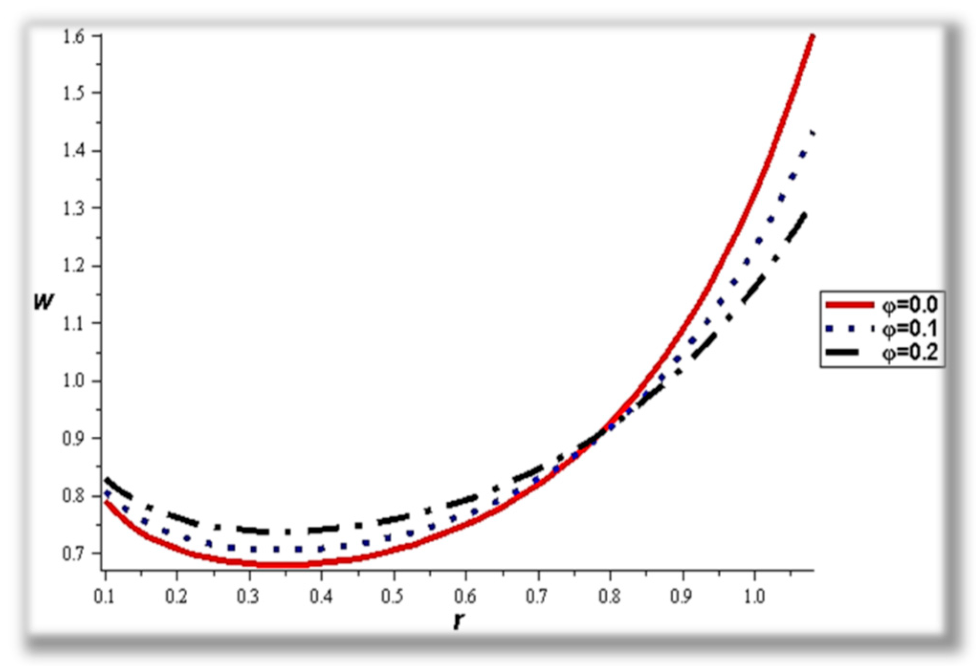
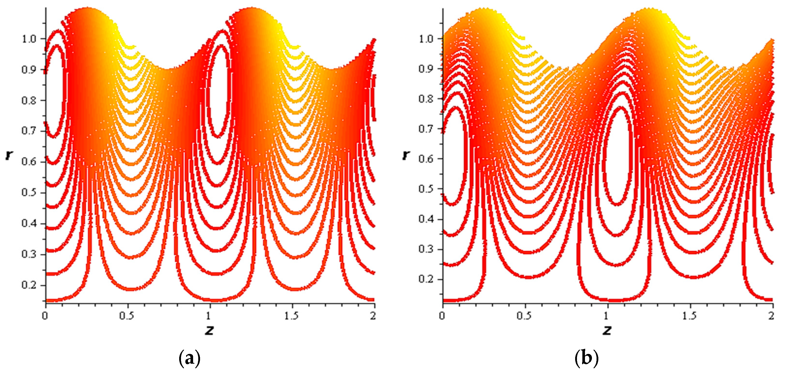
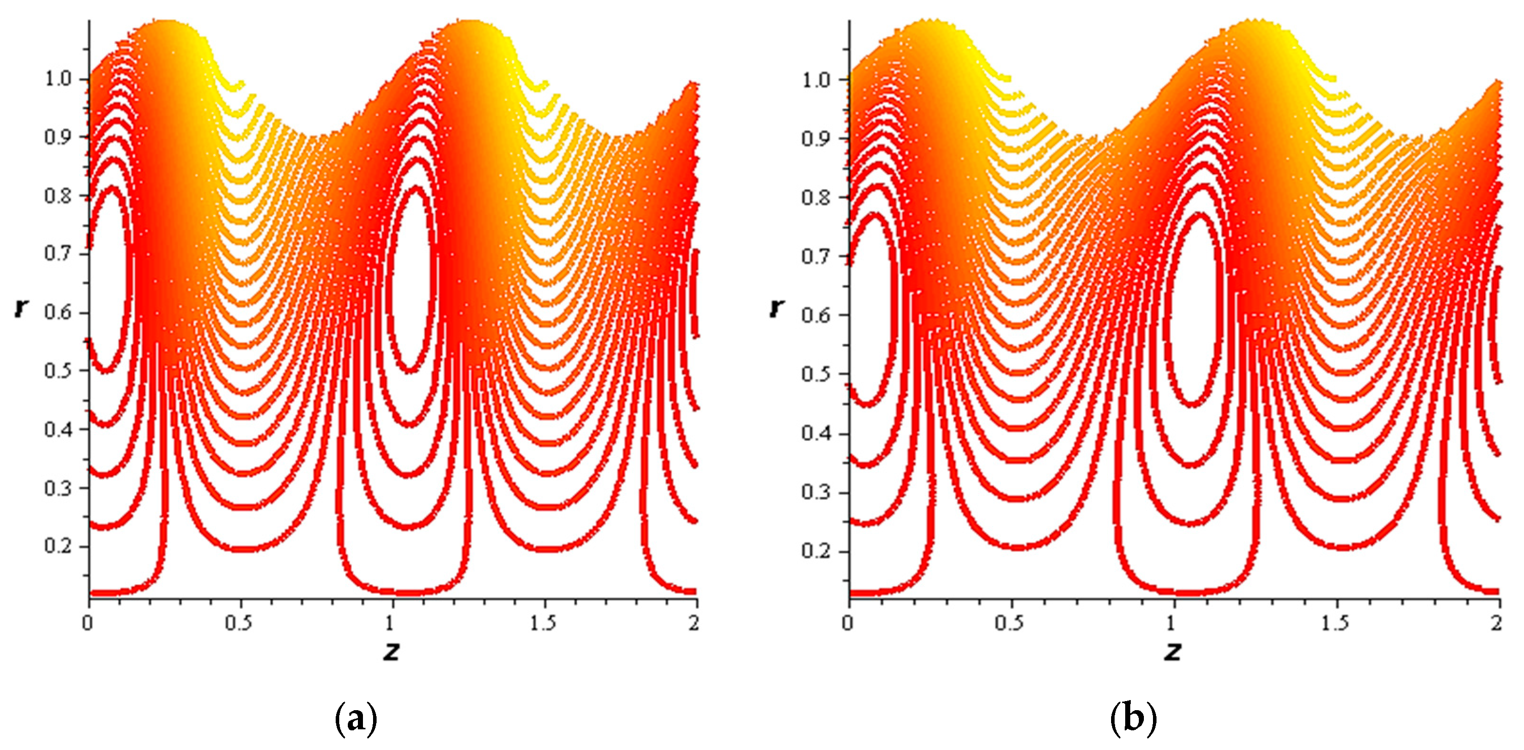
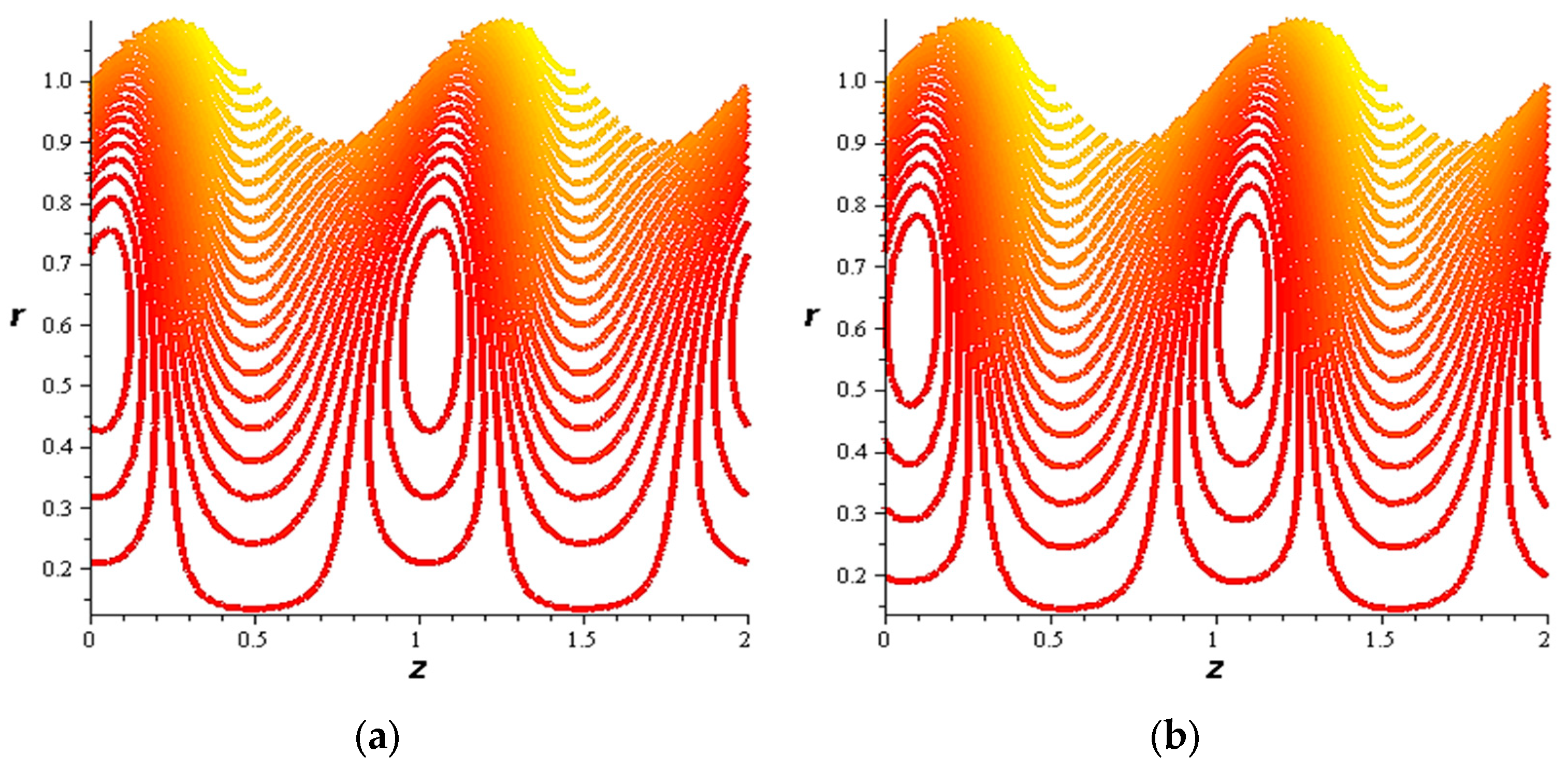
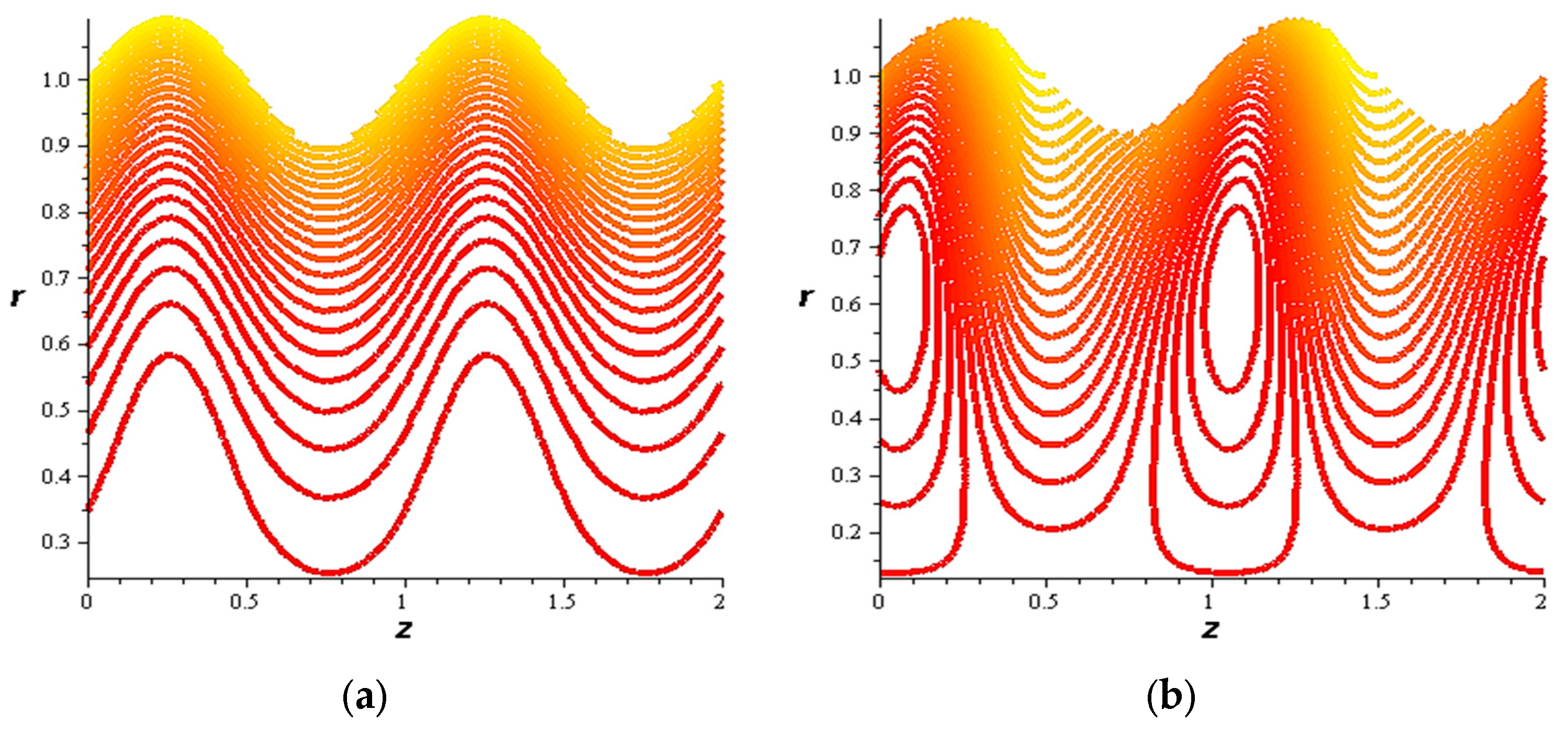
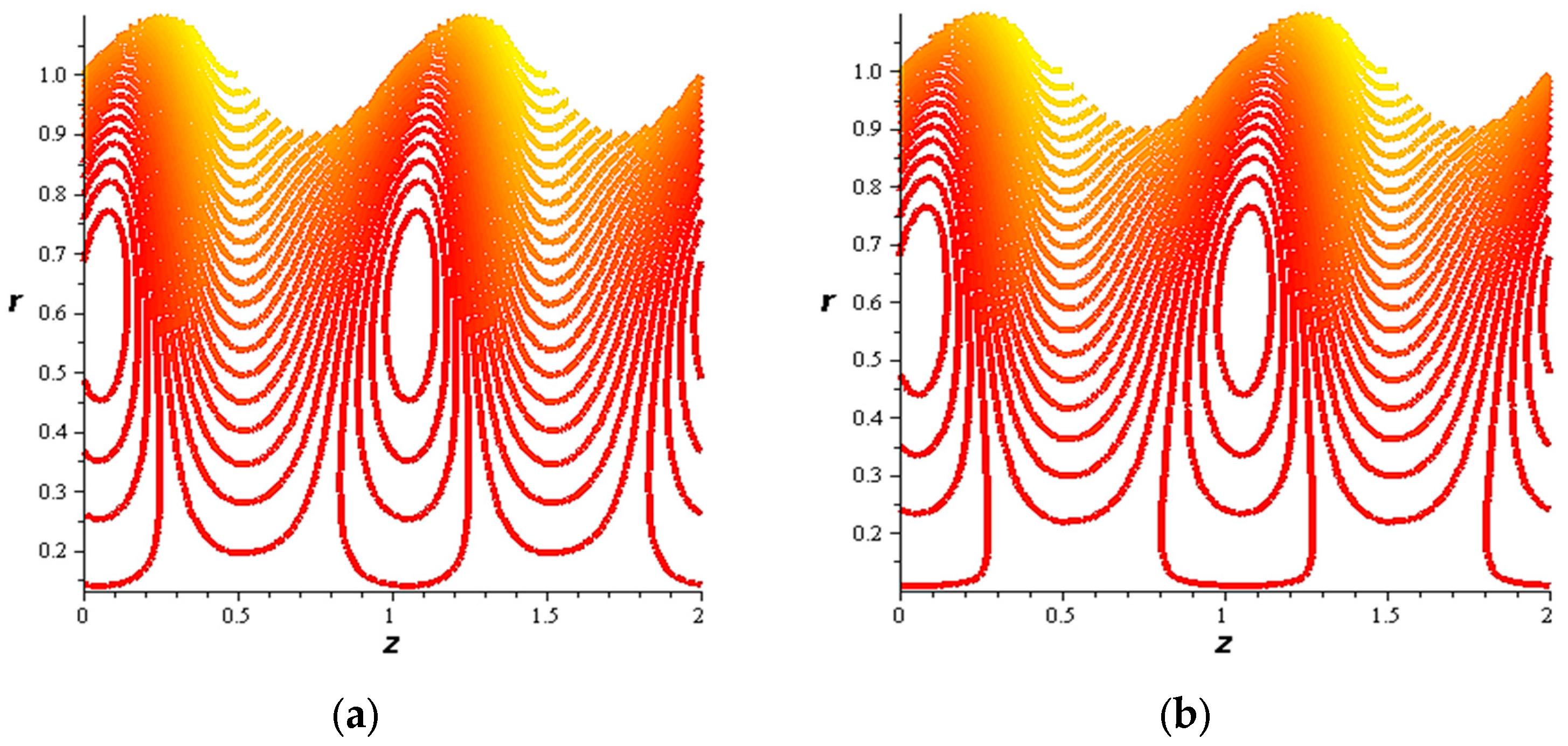
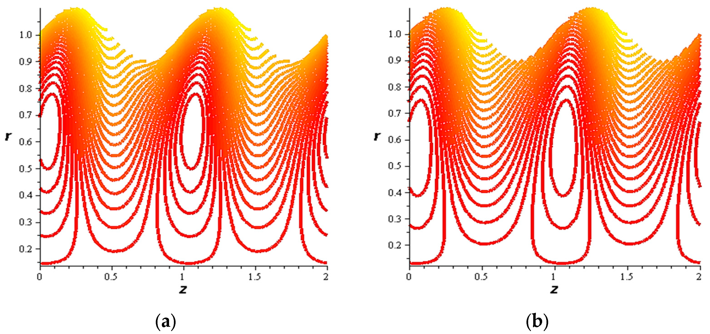
  • For both slipping and without slipping, the magnitude of the velocity increases at the artery wall and diminishes at the catheter with nanoparticle concentration, φ, and with catheter size and the amplitude ratio. This effect is evident in the streamlines, as in the presence of nanoparticles, the fluid lines decrease.
  • Increasing velocity with increasing amplitude ratio occurs at most of the interface points between the artery wall and the catheter.
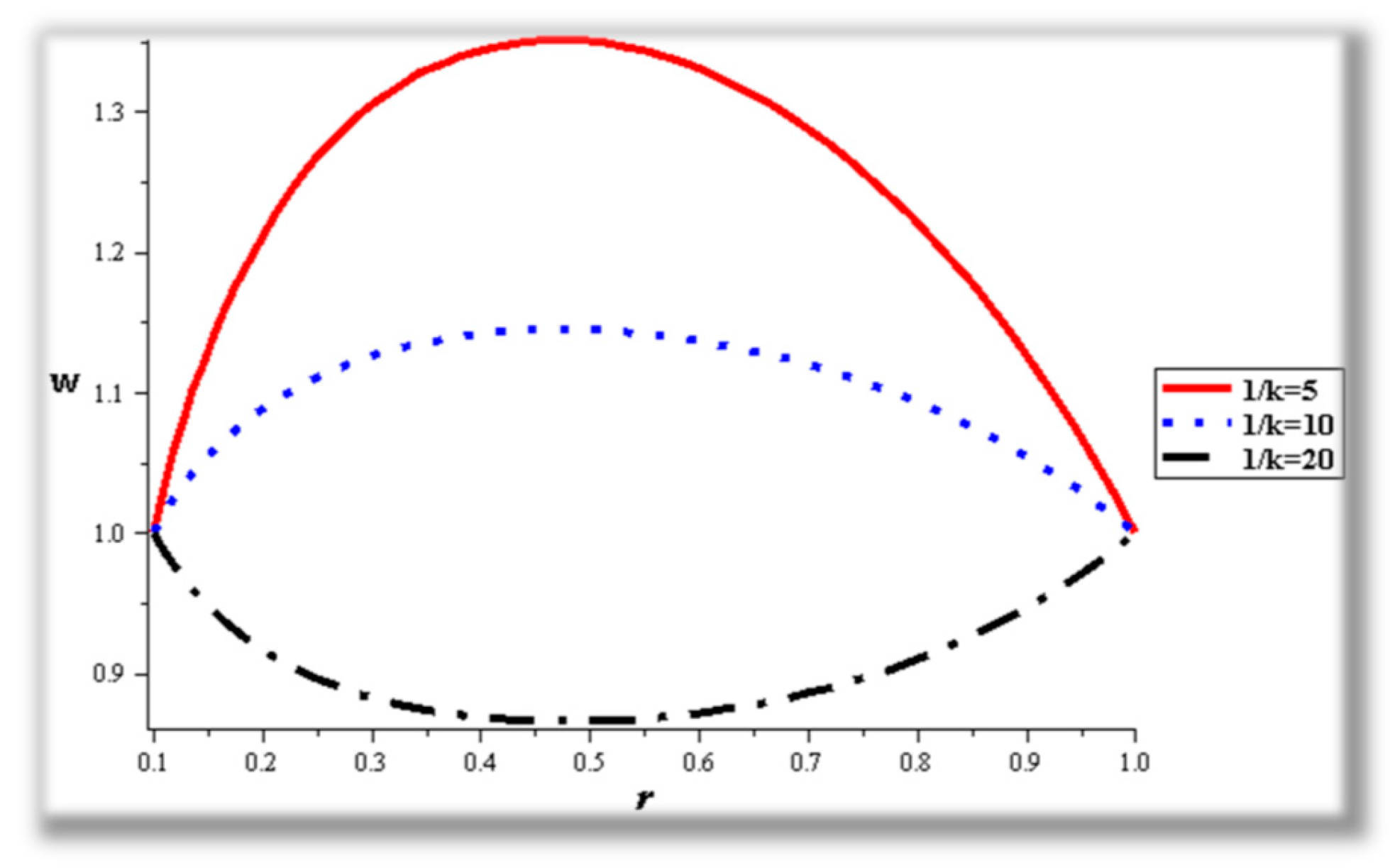
  • The strength of the magnetic field works to obstruct the flow movement and, therefore, it reduces the flow speed in most areas of the artery, but the distribution of speeds increases next to the wall as it depends on the occurrence of slipping. The streamlines are affected by the magnetic field, as increasing the influencing magnetic field leads to a decrease in the flow lines, which leads to an increase in the speed of the fluid layers.
  • The velocity also increases with the presence of a catheter. It is also observed that the slipping on the tube wall increases the velocity, while the slip condition at the catheter decreases the velocity. The sliding that occurs on the artery wall leads to a reduction in vortices on this wall and streamlines the flow lines. The kinetic and thermal energy of the fluid decreases when the catheter moves.
  • By studying the effect of wall properties on flow behavior, it was found that the damping affecting the artery wall, as well as the mass of the cells relative to their area, have the same effect on flow performance, in contrast to tension between the artery wall cells.
One of the important variables that has been studied regarding the flow movement is the effect of the wall due to the nature of the flow, which is called stress at the wall. It was observed that this stress decreases when nanoparticles increase, in contrast to the effect of the magnetic field and also the occurrence of slipping.
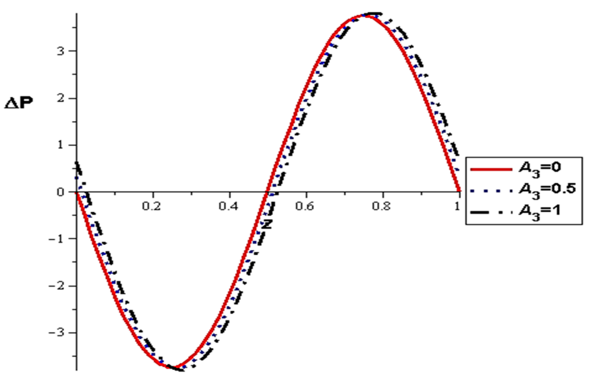
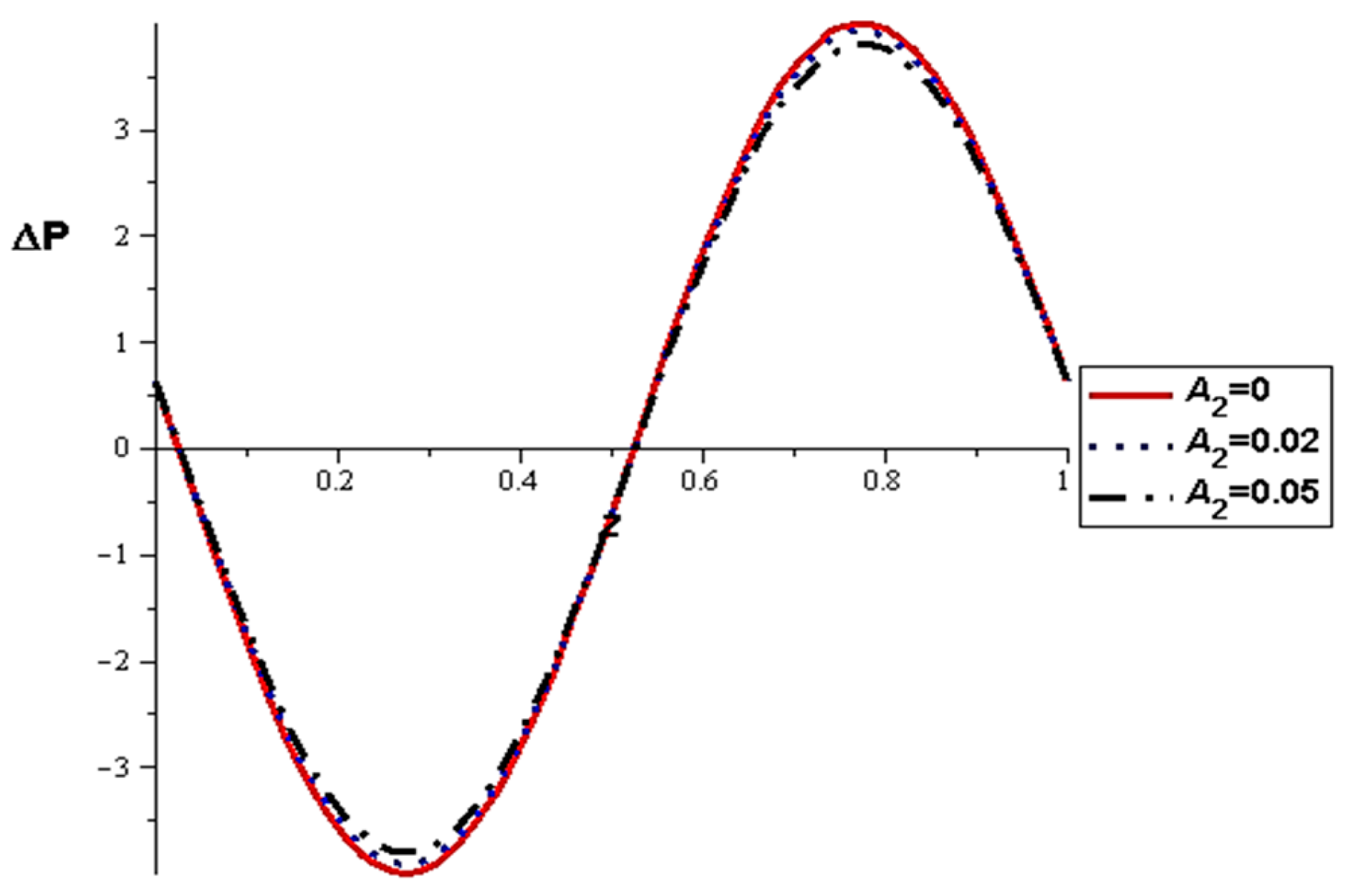
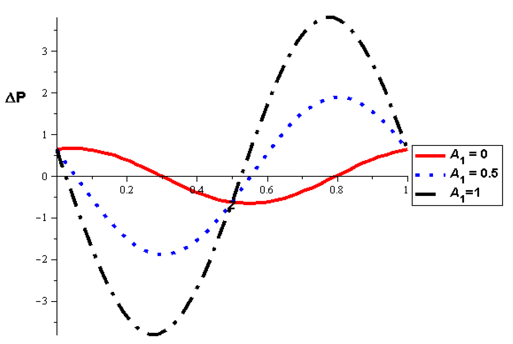
  • The pressure difference depends on the wall properties. It was found that the mass of the wall cells relative to their area decreases the pressure difference, in contrast to the tension between those cells, which increases the pressure difference. Intercellular damping depends on the peristaltic movement of the artery, which determines the increase or decrease in the pressure difference.
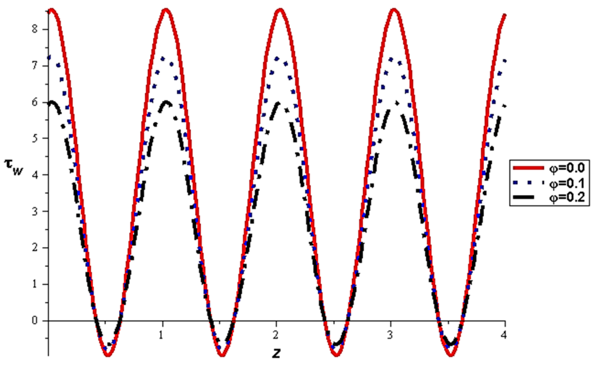
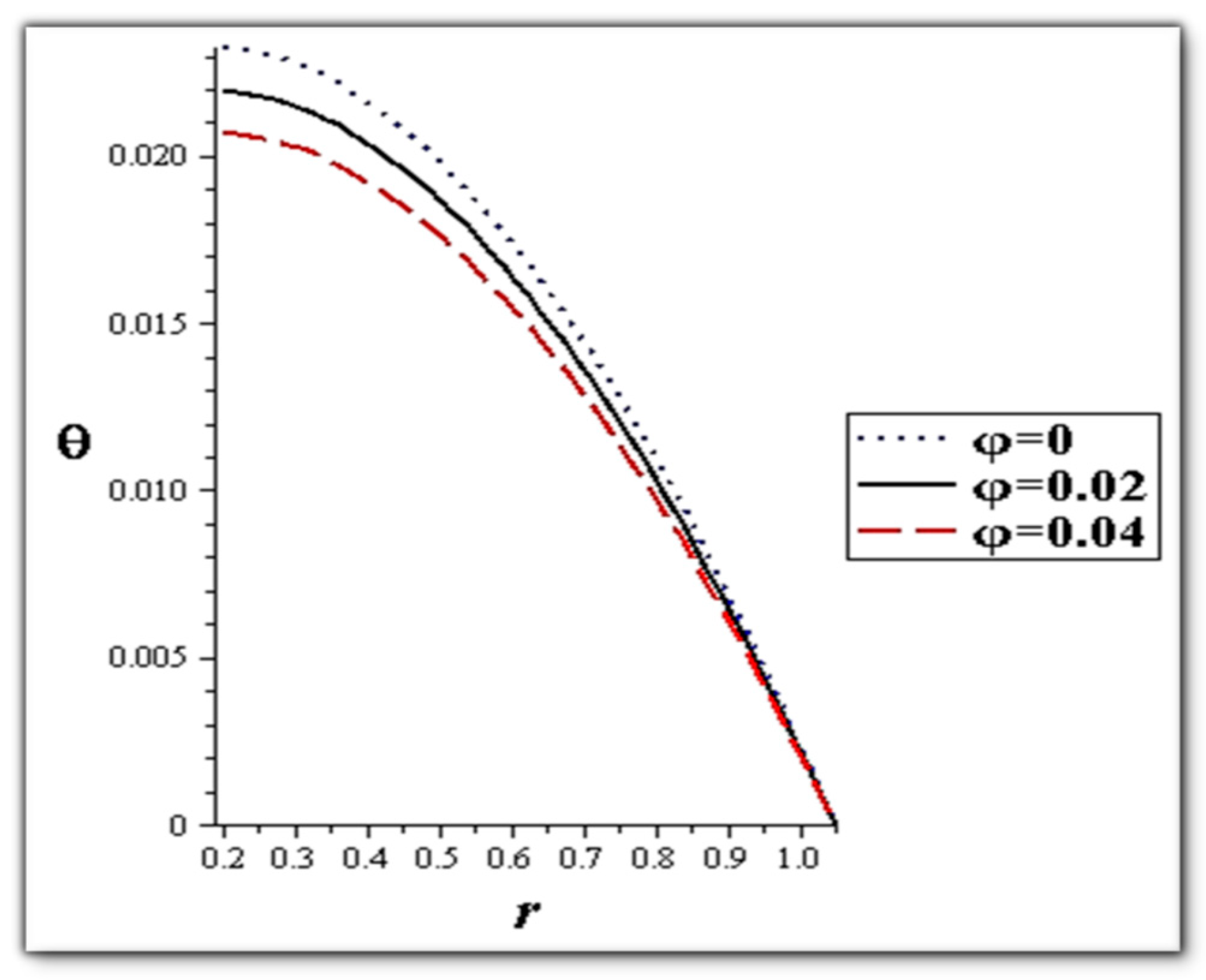
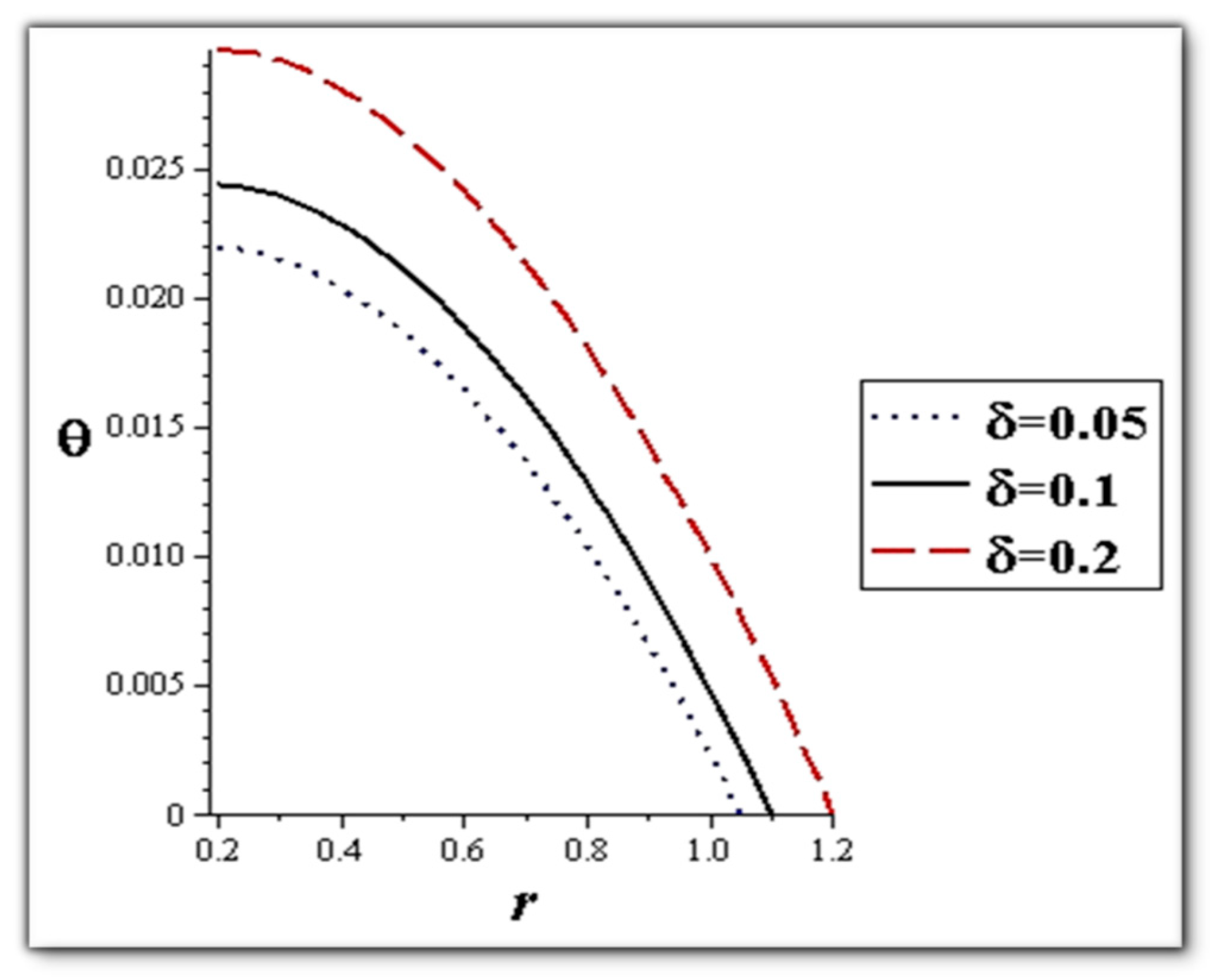
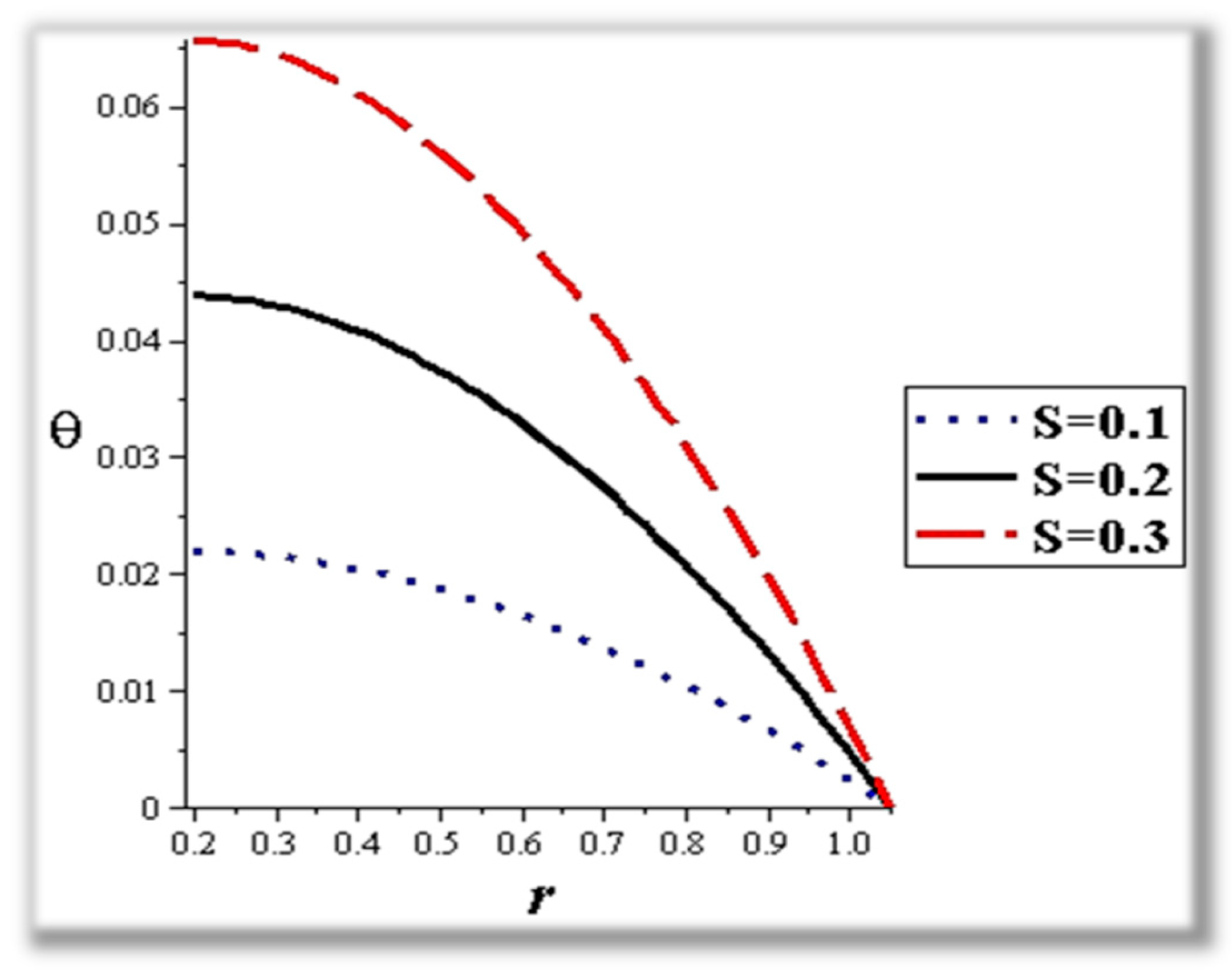
  • The flow rate and amplitude ratio increase the temperature, while the temperature decreases with slip conditions and increasing fluid suspension concentration.
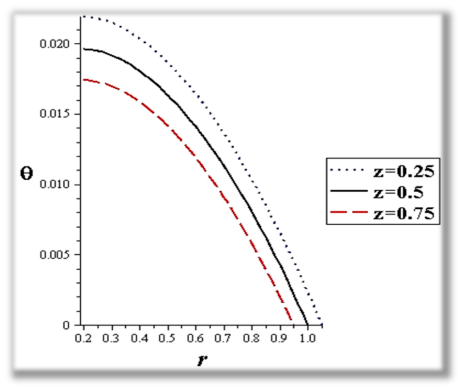
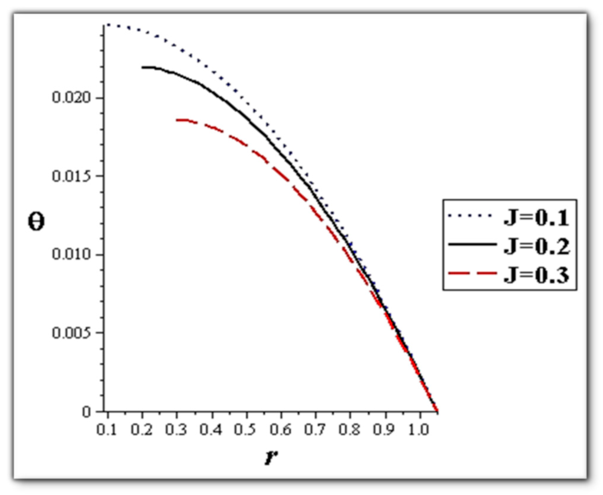
  • Catheter size enhances the thermal effect.
Finally, this study enabled us to observe the simultaneous effects of slip conditions and heat transfer on a nanoparticle fluid suspension with peristaltic transport in a circular pipe. Really, the present investigation elucidates the peristaltic pumping of blood through narrow catheterized arteries. In future work, we look forward to studying various other effects on the flow movement of nanoparticles, including mass transfer, skin friction, Nusselet number, Schmidt number, Eckert number, and Prandtl number while also studying different types of basic fluids with different mathematical models.

Author Contributions

R.A. and I.E.; Methodology, M.M. and R.A.; Software, M.M., Validation, H.A. and I.E.; Resources, R.A.; Data curation, R.A. and I.E.; Writing—original draft, M.M.; Writing—review & editing, M.M., I.E., R.A. and H.A.; Project administration, I.E. and H.A.; Funding acquisition, H.A. All authors have read and agreed to the published version of the manuscript.

Funding

This research was funded by Taif University, Saudi Arabia, Project No. (TU-DSPP-2024-92).

Institutional Review Board Statement

Not applicable.

Data Availability Statement

The author elects to not share data.

Acknowledgments

The authors extend their appreciation to Taif University, Saudi Arabia, for supporting this work through project number (TU-DSPP-2024-92).

Conflicts of Interest

The authors declare no conflicts of interest.

Nomenclature

SymbolDefinitionUnit
a1Catheter radiuscm
c p Specific heat at constant pressureJoule/kg.K
DSource term of heatJoule
HaHartmann numberDimensionless
J = a1/ R o Catheter sizeDimensionless
KnfNanofluid thermal conductivityW/(m·K)
1/k`Permeability parametercm2
Kn = Ω/ R o Knudsen numberDimensionless
λ Wave lengthcm
P PressureN/cm2
r׳, z׳Polar coordinatescm
Re = ρ f u o λ / µ f Reynolds numberDimensionless
R o Main tube radiuscm
SSource term of heatDimensionless
T׳TemperatureK
ToAmbient temperatureK
t`Timesec
u׳, w׳Velocity componentscm/s
uoWave propagation velocitycm/s
β o Constant applied magnetic fieldTesla (T)
δ ׳ Amplitude of the peristaltic wavecm
δ = δ ׳ / R o Amplitude ratio in tubeDimensionless
ε = R o / λ Wave numberDimensionless
θ Dimensionless temperatureDimensionless
ΩMean free pathcm
μ fCoefficient of dynamic viscosity of the fluidPa.s
μ nfCoefficient of dynamic viscosity of the nanofluid mixturePa.s
ρDensityKg/cm3
σ Electrical conductivitySimens/cm
φNanoparticle concentrationDimensionless
ψ Stream functioncm2/s
m1Wall tension of the arteryKg.cm/s2
m2Mass per unit area of the arteryKg/cm2
m3Viscous damping coefficient of the arteryKg/s

References

  1. Pandey, A.; Teixeira, J.A.C. Current Developments in Biotechnology and Bioengineering. In Foundations of Biotechnology and Bioengineering; Elsevier: Amsterdam, The Netherlands, 2016. [Google Scholar]
  2. Huang, Y.; Lan, Y.; Thomson, Y.S.; Fang, J.A.; Hoffmann, W.C.; Lacey, R.E. Development of soft computing and applications in agricultural and biological engineering. Comput. Electron. Agric. 2010, 71, 107–127. [Google Scholar] [CrossRef]
  3. Norotte, C.; Marga, F.S.; Niklason, L.E.; Forgacs, G. Scaffold-free vascular tissue engineering using bioprinting. Biomaterials 2009, 30, 5910–5917. [Google Scholar] [CrossRef]
  4. Pettet, G.J.; Malda, J. Mathematicians in Biologists. Clothes: A Clarion Call for collaboration. In Biotechnology and Bioengineering; Nova Science Publishers: New York, NY, USA, 2008. [Google Scholar]
  5. Marieb, E.N.; Hoehn, K. Human Anatomy and Physiology, 8th ed.; Benjamin Cummings/Pearson: San Francisco, CA, USA, 2010. [Google Scholar]
  6. Tripathi, D. Peristaltic transport of fractional Maxwell fluids in uniform tubes: Applications in endoscopy. Comput. Math. Appl. 2011, 62, 1116–1126. [Google Scholar] [CrossRef]
  7. Sobh, A.M. Slip flow in peristaltic transport of a Carreau fluid in an asymmetric channel. Can. J. Phys. 2009, 87, 957–965. [Google Scholar] [CrossRef]
  8. Medhavi, A.; Singh, U.K. A two-layered suspension flow induced by peristaltic waves. Int. J. Fluid Mech. 2008, 35, 258–272. [Google Scholar] [CrossRef]
  9. Abd Elnaby, M.A.; Haroun, M.H. Influence of compliant wall properties on peristaltic motion in two-dimensional channel. Commun. Nonlinear Sci. Numer. Simul. 2008, 13, 738–752. [Google Scholar]
  10. El-Desoky, I.M. Influence of slip condition on peristaltic transport of a compressible Maxwell fluid through porous medium in a tube. Int. J. Appl. Math. Mech. 2012, 2, 99–117. [Google Scholar]
  11. Liu, J.; Lu, Y. Preparation of aptamer-linked gold nanoparticle purple aggregates for colorimetric sensing of analytes. Nat. Protoc. 2006, 1, 246–252. [Google Scholar] [CrossRef] [PubMed]
  12. Lassoued, A.; Lassoued, M.S.; Dkhil, B.; Ammar, S.; Gadri, A. Synthesis, structural, morphological, optical and magnetic characterization of iron oxide (α-Fe2O3) nanoparticles by precipitation method: Effect of varying the nature of precursor. Phys. E Low-Dimens. Syst. Nanostruct. 2018, 97, 328–334. [Google Scholar] [CrossRef]
  13. Khan, S.; Dewang, Y.; Raghuwanshi, J.; Shrivastava, A.; Sharma, V. Nanoparticles as fuel additive for improving performance and reducing exhaust emissions of internal combustion engines. Int. J. Environ. Anal. Chem. 2022, 102, 319–341. [Google Scholar] [CrossRef]
  14. Khorramshokouh, S.; Pirouzfar, V.; Kazerouni, Y.; Fayyazbakhsh, A.; Abedini, R. Improving the properties and engine performance of diesel–methanol–nanoparticle blend fuels via optimization of the emissions and engine performance. Energy Fuels 2016, 30, 8200–8208. [Google Scholar] [CrossRef]
  15. Sarma, C.J.; Sharma, P.; Bora, B.J.; Bora, D.K.; Senthilkumar, N.; Balakrishnan, D.; Ayesh, A.I. Improving the combustion and emission performance of a diesel engine powered with mahua biodiesel and TiO2 nanoparticles additive. Alex. Eng. J. 2023, 72, 387–398. [Google Scholar] [CrossRef]
  16. Beg, O.A.; Akbar, N.S.; Huda, A.B.; Khan, M.Y. Dynamics of variable-viscosity nanofluid flow with heat transfer in a flexible vertical tube under peristaltic waves. Results Phys. 2017, 7, 413–425. [Google Scholar]
  17. Nicolle, L.E. Catheter associated urinary tract infections. Antimicrob. Resist. Infect. Control 2014, 3, 23. [Google Scholar] [CrossRef] [PubMed]
  18. Srivastava, V.P.; Rastogi, R. Blood flow through a stenosed catheterized artery: Effects of hematocrit and stenosis shape. Comput. Math. Appl. 2010, 59, 1377–1385. [Google Scholar] [CrossRef]
  19. Cho, S.A.; Jang, Y.E.; Ji, S.H.; Kim, E.H.; Lee, J.H.; Kim, H.S.; Kim, J.T. Ultrasound-guided arterial catheterization. Anesth. Pain Med. 2021, 16, 119. [Google Scholar] [CrossRef] [PubMed]
  20. Dolui, S.; Bhaumik, B.; De, S. Combined effect of induced magnetic field and thermal radiation on ternary hybrid nanofluid flow through an inclined catheterized artery with multiple stenosis. Chem. Phys. Lett. 2023, 811, 140209. [Google Scholar] [CrossRef]
  21. Sher Akbar, N.; Nadeem, S. Simulation of peristaltic flow of chyme in small intestine for couple stress Fluid. Meccanica 2014, 49, 325–334. [Google Scholar] [CrossRef]
  22. Ellahi, R.; Bhatti, M.M.; Vafai, K. Effects of heat and mass transfer on peristaltic flow in a non-uniform rectangular duct. Int. J. Heat Mass Transf. 2014, 71, 706–719. [Google Scholar] [CrossRef]
  23. Vajravelu, K.; Sreenadh, S.; Lakshminarayana, P. The influence of heat transfer on peristaltic transport of a Jeffrey fluid in a vertical porous stratum. Commun. Nonlinear Sci. Numer. Simul. 2011, 16, 3107–3125. [Google Scholar] [CrossRef]
  24. Akbar, N.S.; Nadeem, S.; Hayat, T.; Hendi, A.A. Effects of heat and mass transfer on the peristaltic flow of hyperbolic tangent fluid in an annulus. Int. J. Heat Mass Transf. 2011, 54, 4360–4369. [Google Scholar] [CrossRef]
  25. Nadeem, S.; Akbar, N.S. Influence of heat and mass transfer on the peristaltic flow of a Johnson Segalman fluid in a vertical asymmetric channel with induced MHD. J. Taiwan Inst. Chem. Eng. 2011, 42, 58–66. [Google Scholar] [CrossRef]
  26. Khan, L.A.; Raza, M.; Mir, N.A.; Ellahi, R. Effects of different shapes of nanoparticles on peristaltic flow of MHD nanofluids filled in an asymmetric channel: A novel mode for heat transfer enhancement. J. Therm. Anal. Calorim. 2020, 140, 879–890. [Google Scholar] [CrossRef]
  27. Riaz, A.; Alolaiyan, H.; Razaq, A. Convective heat transfer and magnetohydrodynamics across a peristaltic channel coated with nonlinear nanofluid. Coatings 2019, 9, 816. [Google Scholar] [CrossRef]
  28. Abd-Alla, A.M.; Abo-Dahab, S.M.; Thabet, E.N.; Abdelhafez, M.A. Heat and mass transfer for MHD peristaltic flow in a micropolar nanofluid: Mathematical model with thermophysical features. Sci. Rep. 2022, 12, 21540. [Google Scholar] [CrossRef] [PubMed]
  29. Beavers, G.S.; Joseph, D.D. Boundary conditions at a naturally permeable wall. J. Fluid Mech. 1967, 30, 197–207. [Google Scholar] [CrossRef]
  30. Wang, C. Stagnation flows with slip: Exact solutions of the Navier-Stokes equations. Z. Angew. Math. Und Phys. ZAMP 2003, 54, 184–189. [Google Scholar] [CrossRef]
  31. Ahmed, M.M.; Eldesoky, I.M.; Abdelsalam, S.I.; El-askary, W.A. The integrated thermal effect in conjunction with slip conditions on peristaltically induced particle fluid transport in a catheterized pipe. J. Porous Media 2020, 23, 695–713. [Google Scholar]
  32. Zhu, Y.; Granick, S. Limits of the hydrodynamic no-slip boundary condition. Phys. Rev. Lett. 2002, 88, 106102. [Google Scholar] [CrossRef] [PubMed]
  33. Mishra, A. Thompson and Troian slip effects on ternary hybrid nanofluid flow over a permeable plate with chemical reaction. Numer. Heat Transf. Part B Fundam. 2024, 1–29.–29. [Google Scholar] [CrossRef]
  34. Eldesoky, I.M.; Abumandour, R.M.; Kamel, M.H.; Abdelwahab, E.T. The combined influences of heat transfer, compliant wall properties and slip conditions on the peristaltic flow through tube. SN Appl. Sci. 2019, 1, 897. [Google Scholar] [CrossRef]
  35. Khan, A.A.; Tariq, H. Influence of wall properties on the peristaltic flow of a dusty Walter’s B fluid. J. Braz. Soc. Mech. Sci. Eng. 2018, 40, 368. [Google Scholar] [CrossRef]
  36. Eldesoky, I.M.; Abdelsalam, S.I.; El-Askary, W.A.; Ahmed, M.M. Concurrent development of thermal energy with magnetic field on a particle-fluid suspension through a porous conduit. Bio Nanosci. 2019, 9, 186–202. [Google Scholar] [CrossRef]
  37. Hasany, S.; Ahmed, I.; Rajan, J.; Rehman, A. Systematic review of the preparation techniques of iron oxide magnetic nanoparticles. Nanosci. Nanotechnol. 2012, 2, 148–158. [Google Scholar] [CrossRef]
  38. Eldesoky, I.M.; Abdelsalam, S.I.; El-Askary, W.A.; El-Refaey, A.M.; Ahmed, M.M. Joint effect of magnetic field and heat transfer on particulate fluid suspension in a catheterized wavy tube. BioNanoScience 2019, 9, 723–739. [Google Scholar] [CrossRef]
  39. Akbar, N.S.; Maraj, E.; Butt, A.W. Copper nanoparticles impinging on a curved channel with compliant walls and peristalsis. Eur. Phys. J. Plus 2014, 129, 193. [Google Scholar] [CrossRef]
  40. Shapiro, A.H.; Jaffrin, M.Y.; Weinberg, S.L. Peristaltic pumping with long wavelengths at low Reynolds number. J. Fluid Mech. 1969, 37, 799–825. [Google Scholar] [CrossRef]
  41. Afifi, N.; Mahmoud, S.; Al-Isede, H. Effect of magnetic field and wall properties on peristaltic motion of micropolar fluid. Int. Math. Forum 2011, 6, 1345–1356. [Google Scholar]
Figure 1. Mathematical formulation of the catheterized artery.
Mathematics 12 02024 g001
Figure 2. Velocity with artery wall damping (A3) at (A1 = 1, Kn = 0, A2 = 0.01, φ = 0, Ha = 1.5, δ = 0.2, 1/k = 0, J = 0).
Mathematics 12 02024 g002
Figure 3. Velocity with different artery locations at (Kn = 0, A1 = 1, A2 = 0.05, A3 = 1, φ = 0.2, Ha = 3, k = 0.1, J = 0.1).
Mathematics 12 02024 g003
Figure 4. Velocity distribution with wall amplitude ratio (δ) at (φ = 0.2, Ha = 3, k = 0.1, J = 0.1 A1 = 1, A3 = 1, A2 = 0.05). (a) Kn = 0.0; (b) Kn = 0.15.
Mathematics 12 02024 g004
Figure 5. Velocity with catheter size (J) at (Kn = 0.15, A1 = 1, A2 = 0.05, A3 = 1, φ = 0.2, Ha = 3, k = 0.1, δ = 0.1).
Mathematics 12 02024 g005
Figure 6. Velocity with magnetic field (Ha) at (Kn = 0.15, A1 = 1, A2 = 0.05, A3 = 1, k = 0.1, φ = 0.2, J = 0.1, δ = 0.1).
Mathematics 12 02024 g006
Figure 7. Velocity with Knudsen number at (A1 = 1, A2 = 0.05, A3 = 1, φ = 0.2, Ha = 3, k = 0.1, J = 0.1, δ = 0.1).
Mathematics 12 02024 g007
Figure 8. Velocity with artery wall damping (A3) at (Kn = 0.15, A1 = 1, A2 = 0.05, φ = 0.2, Ha = 3, k = 0.1, J = 0.1, δ = 0.1).
Mathematics 12 02024 g008
Figure 9. Velocity with artery wall tension (A1) at (Kn = 0.15, φ = 0.2, A3 = 1, Ha = 3, k = 0.1, A2 = 0.05, J = 0.1, δ = 0.1).
Mathematics 12 02024 g009
Figure 10. Velocity with mass per unit area of the artery (A2) at (Kn = 0.15, k = 0.1, A3 = 1, A1 = 1, J = 0.1, φ = 0.2, Ha = 3, δ = 0.1).
Mathematics 12 02024 g010
Figure 11. Velocity with nanoparticle concentration (φ)at (A2 = 0.05, A3 = 1, A1 = 1, Ha = 3, k = 0.1, J = 0.1, δ = 0.1, Kn = 0.15).
Mathematics 12 02024 g011
Figure 12. Velocity with permeability (1/k) at (Kn = 0, A1 = 1, A2 = 0.05, A3 = 0.1, φ = 0.2, Ha = 3, J = 0.1, δ = 0.1).
Mathematics 12 02024 g012
Figure 13. Wall wave and catheter motions at (Kn = 0, A1 = 1, A2 = 0.01, A3 = 0.1, φ = 0.02, k = 0.1, J = 0.2, δ = 0.2).
Mathematics 12 02024 g013
Figure 14. Streamlines with Knudsen number at (δ = 0.1, φ = 0.2, Ha = 3, A1 = 1, k = 0.1, A2 = 0.02, J = 0.1, A3 = 1). (a) Kn = 0; (b) Kn = 0.15.
Mathematics 12 02024 g014
Figure 15. Streamlines with Hartman number at (δ = 0.1, A1 = 1, Kn = 0.15, A2 = 0.02, φ = 0.2, k = 0.1, A3 = 1, J = 0.1). (a) Ha = 1; (b) Ha = 3.
Mathematics 12 02024 g015
Figure 16. Streamlines with wall damping at (A1 = 1, A2 = 0.02, Ha = 3, δ = 0.1, Kn = 0.15, φ = 0.2, k = 0.1, J = 0.1). (a) A3 = 0; (b) A3 = 2.
Mathematics 12 02024 g016
Figure 17. Streamlines with artery wall tension (A1) at (A3 = 1, A2 = 0.02, Ha = 3, δ = 0.1, Kn = 0.15, φ = 0.2, k = 0.1, J = 0.1). (a) A1 = 0; (b) A1 = 1.
Mathematics 12 02024 g017
Figure 18. Streamlines with mass per unit area of the artery (A2) at (A3 = 1, A1 = 1, Ha = 3, δ = 0.1, Kn = 0.15, φ = 0.2, k = 0.1, J = 0.1). (a) A2 = 0; (b) A2 = 0.05.
Mathematics 12 02024 g018
Figure 19. Streamlines with nanofluid concentration (φ) at (Ha = 3, δ = 0.1, A2 = 0.02, Kn = 0.15, A3 = 1, k = 0.1, A1 = 1, J = 0.1). (a) φ = 0; (b) φ = 0.3.
Mathematics 12 02024 g019
Figure 20. Shear stress at the artery wall with (φ) at (A2 = 0.05, A3 = 1, A1 = 1, Ha = 3, δ = 0.1, Kn = 0, k = 0.1, J = 0.1).
Mathematics 12 02024 g020
Figure 21. Shear stress at the artery wall with Ha at (φ = 0.2, A2 = 0.05, A3 = 1, A1 = 1, δ = 0.1, Kn = 0, k = 0.1, J = 0.1).
Mathematics 12 02024 g021
Figure 22. Shear stress at the artery wall with Kn at (φ = 0.2, A2 = 0.05, A3 = 1, A1 = 1, δ = 0.1, Ha = 3, k = 0.1, J = 0.1).
Mathematics 12 02024 g022
Figure 23. Pressure difference with artery wall damping (A3) at (A2 = 0.05, A1 = 1, δ = 0.1, J = 0.1).
Mathematics 12 02024 g023
Figure 24. Pressure difference with mass per unit area of the artery (A2) at (A3 = 1, A1 = 1, δ = 0.1, J = 0.1).
Mathematics 12 02024 g024
Figure 25. Pressure difference with artery wall tension (A1) at (A3 = 1, A2 = 0.05, δ = 0.1, J = 0.1).
Mathematics 12 02024 g025
Figure 26. Temperature distribution with the axial coordinate (z) at (δ = 0.05, φ = 0.02, J = 0.2, S = 0.1).
Mathematics 12 02024 g026
Figure 27. Temperature distribution with concentration of nanoparticles (φ) at (δ = 0.05, J = 0.2, S = 0.1).
Mathematics 12 02024 g027
Figure 28. Temperature distribution with the amplitude ratio (δ) at (φ = 0.02, S = 0.1, J = 0.2).
Mathematics 12 02024 g028
Figure 29. Temperature distribution with catheter size (J) at (δ = 0.05, S = 0.1, φ = 0.02).
Mathematics 12 02024 g029
Figure 30. Temperature distribution with heat source at (φ = 0.02, J = 0.2, δ = 0.05).
Mathematics 12 02024 g030
Disclaimer/Publisher’s Note: The statements, opinions and data contained in all publications are solely those of the individual author(s) and contributor(s) and not of MDPI and/or the editor(s). MDPI and/or the editor(s) disclaim responsibility for any injury to people or property resulting from any ideas, methods, instructions or products referred to in the content.

