Abstract
Spiral bevel gear drives are widely used in mechanical transmission devices due to their compact structure, smooth transmission, and cost-effectiveness. With the continuous improvement in mechanical product quality, higher and higher requirements are set for the precision, smoothness, and power density of gear transmission devices. Chatter can lead to poor workpiece surface finish on spiral bevel gears, excessive tool wear, and even damage to machine tools. Therefore, the effective prediction of milling chatter during the processing of spiral bevel gears is essential. Regenerative chatter is one of the most fundamental types of vibration in machining processes. This paper presents an improved fully discrete algorithm for predicting the stability of time-delayed cutting in the milling process of spiral bevel gears. The method is validated using single- and double-degree-of-freedom models, demonstrating its accuracy and computational efficiency. The results show that the proposed method improves computational efficiency while ensuring accuracy.
MSC:
34D20
1. Introduction
In the actual machining process of spiral bevel gears, to improve efficiency, it is common to increase spindle speed, feed rate, and cutting depth. However, during cutting, chatter can occur under certain parameter combinations, leading to increased dynamic loads, affecting the machining quality of spiral bevel gears, reducing efficiency, and impacting the lifespan of machine tools and cutting tools. Therefore, the prediction of chatter stability is significant for ensuring stable machining and enhancing production efficiency.
Many methods have been proposed for predicting processing stability. Smith and Tlusty [1] proposed a method for generating stabilization lobes by simulating chirp vibrations during milling in the time domain. Sridhar et al. [2] developed a mathematical model describing the dynamic milling process and solved it numerically. Minis and Yanushevsky [3] proposed a comprehensive analytical method and solved a two-dimensional milling problem by introducing the periodic differential equation. Altintas and Budak [4] proposed an analytical method (ZOA method) based on the average of Fourier series of dynamic milling coefficients for the prediction of milling stable lobes. Yang et al. [5] proposed a precise integration-based third-order full-discretization method that can be both accurate and efficient in milling stability prediction without the need for any inverse matrix calculation. Ji et al. [6] established a new milling dynamical model which simultaneously considers the regenerative effect, mode coupling effect, and process damping. Dai et al. [7] started from the numerical solution of the delay differential equation; this paper first gave a detailed mathematical derivation to demonstrate the beingness of the numerical calculation errors at the crucial step for two equal interval calculation methods of cutting force coefficients and then discussed the impact of the errors on the convergence effect and prediction accuracy. Shi et al. [8] developed an algorithm for predicting the stability lobes for face milling processes. Zhang et al. [9] presented numerical integration scheme-based semi-discretization methods (NISDMs) for milling stability prediction. Ye et al. [10] proposed a second-order full-discretization method for milling stability prediction based on the direct integration scheme. Liu et al. [11] proposed a modified full-discretization method for milling stability prediction based on timestep control. Ding et al. [12] proposed the full-discretization method (FDM) based on the direct integration scheme to obtain predictions of SLD efficiently. Sellmeier and Denkena [13] used one of the semi-discretization schemes, Ackermann’s method, to investigate the stability of an unequally pitched end mill. It was observed that when the time variance in the system was taken into account, stable islands would occur in the charts. By using adapted and time-averaged versions of the SDM, Sims et al. [14] investigated the stability of variable pitch and variable helix end mills and showed the phenomenon of cyclic-fold bifurcations at low radial immersion milling. Quintana et al. [15] determined the stability charts of a milling process by applying a sound mapping methodology. Jin et al. [16] extended this method for milling stability prediction with multiple delays. Ozoegwu [17] reported high-order vector numerical integration schemes (ONISMs) to analyze milling stability. D.S. Merdol et al. [18] presented generalized virtual simulation and optimization strategies to predict and optimize the performance of milling processes with up to three axes. Jin et al. [19,20] investigated the effect of tool geometry on the stability trend of variable pitch or variable helix milling using a modified SD algorithm. Jin et al. [16] proposed an improved semi-discretization method to predict the stability lobes for milling processes with multiple delays. Dai et al. [21] adopted the explicit precise integration method (PIM) to predict the chatter stability of the milling process. However, there is relatively little research on the prediction of stability in the machining process of spiral bevel gears.
This paper proposes an improved full-discretization method for predicting milling stability in the processing of spiral bevel gears. The method in this paper fully discretizes the equations in the computational process and interpolates the fit in each time interval, allowing the equations to be computed in an accurate numerical quantity while reducing the number of computational steps and improving the computational efficiency. This method significantly improves computational efficiency while ensuring prediction accuracy. The rest of this paper is organized as follows: Section 2 describes the mathematical model and numerical scheme. Section 3 conducts calculations for both the single- and double-degree-of-freedom examples, thereby illustrating the computational efficiency of the new method. Section 4 presents the conclusion.
2. Mathematical Model and Algorithm
Without loss of generality, the dynamics of the spiral bevel gear milling process with regenerative effects can be described as an n-dimensional linear time-periodic system with a single discrete time delay. This system is represented in the following state space form:
where is a constant matrix representing the time-invariant properties of the system, while and are two periodic coefficient matrices satisfying and , with T being the period of time delay.
The first step in numerically solving Equation (1) involves discretizing the time period T, dividing it into m small time intervals such that T = mt, where m is an integer. For each time interval , the response of Equation (1) under initial conditions can be obtained through direct integration as follows:
Equation (2) can be equivalently represented as
where . Simultaneously, , or , can be obtained from Equation (3)
The next step involves handling the Duhamel term in Equation (4), i.e., the integral term. Initially, the time delay term is linearly approximated by and , i.e., the two boundary values of the time interval , resulting in
The state term in Equation (4) can also be approximated by linear interpolation using and , the two boundary values of the time interval , resulting in
Similarly, the time-periodic terms and in Equation (4) can be approximated through the linear interpolation of the two boundary values of the time interval , resulting in
where , , and represents the value of at the sampling time . And
where , , and represents the value of at the sampling time .
Substituting Equations (6)–(8) into Equation (4) results in
where
Clearly, , , and can be represented by matrices and , as follows:
Additionally, matrices in Equation (15) can be numerically computed using the Precise Time Integration (PTI) method, eliminating the need to calculate the inverse matrix .
From Equation (9), it is evident that if matrix is non-singular, can be represented as follows:
If matrix is singular, the state item in Equation (6) can be replaced with a zero-order hold term, namely
Subsequently, becomes
where
Based on Equation (19), the discrete mapping can be defined as
where the -dimensional vector is represented as
And is defined as
Now, the transition matrix within a periodic time interval can be constructed using the discrete mapping sequence , that is
where is defined as
Now, according to Floquet theory, the stability of the system can be determined: if all the eigenvalues of the transition matrix have moduli less than 1, the system is stable; otherwise, it is unstable.
3. Validation
This paper validates the proposed method using both single- and double-degree-of-freedom milling models. The biggest difference between the method in this paper and other methods is that both the time delay term and the state delay term are discretized, and interpolated and fitted in each time interval, so that the equations can be carried out to please exact numerical computational quantities, to reduce the number of computational steps and to improve the computational efficiency.
4. Single-Degree-of-Freedom Milling Model
The dynamic equation for the single-degree-of-freedom milling model is
where represents the relative damping, is the angular natural frequency, is the cutting depth, and is the modal mass of the tool. The time delay T equals the tool pass period , where N is the number of teeth on the tool, and is the spindle speed (rev/min). represents the cutting force coefficient, again a periodic function, defined as
and are the tangential and normal linear cutting force coefficients, respectively. is the angular position of the j-th tooth, defined as follows:
The function is defined as follows:
where and are the entry and exit angles of the j-th tooth, respectively.
For up-milling, and ; for down-milling, and , where is the radial immersion ratio.
Let and . Through some simple transformations, the state space form of the single-degree-of-freedom milling model can be represented as
where
To validate the effectiveness of the proposed method, it was compared with the method from reference [16] using the same parameters. The main parameters include the following: number of teeth N = 4, natural frequency , relative damping , cutting force coefficient , , and modal mass .
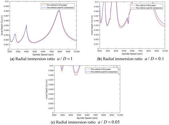
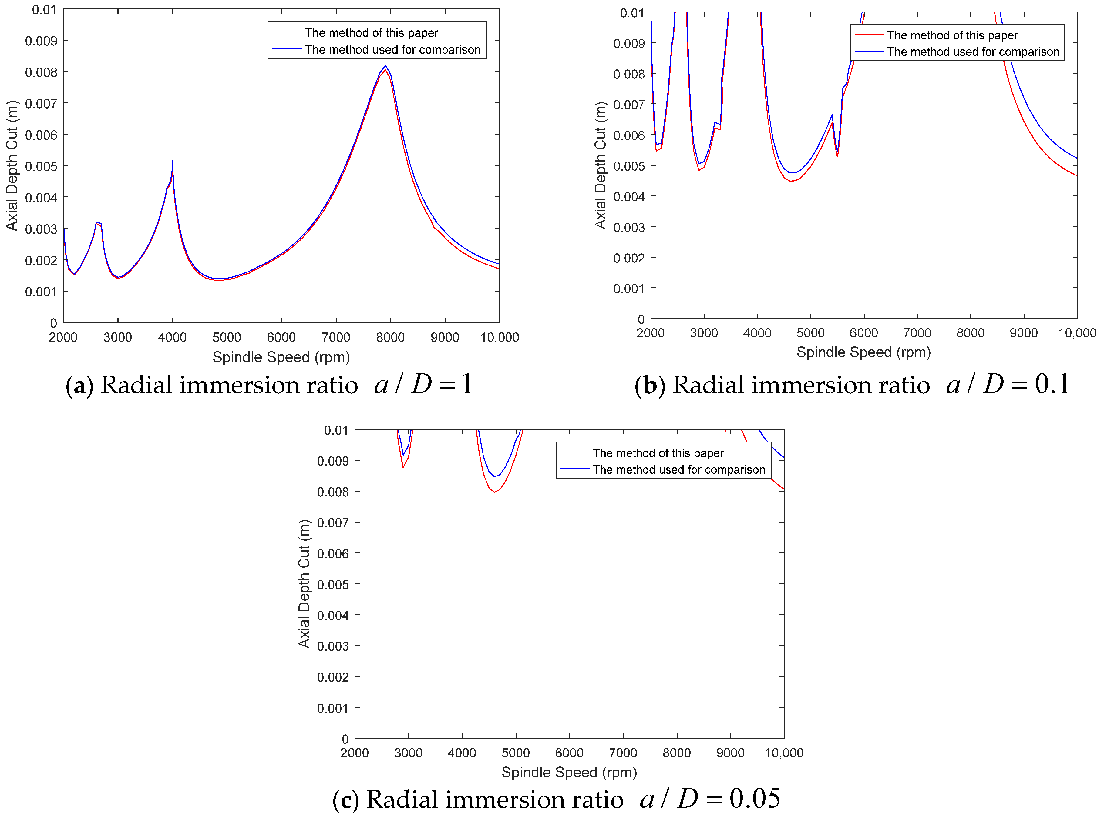
Figure 1 presents the stability diagrams of the single-degree-of-freedom milling model for three different immersion ratios of 1, 0.1, and 0.05. As illustrated in Figure 1, under different radial immersion ratios, the change trend of axial depth cut with the increase in spindle speed is basically the same as that of the reference method, indicating that the calculation results of the two methods are basically the same regardless of the size of the radial immersion ratio. It proves that the method proposed in this paper ensures the accuracy of the calculation.

Figure 1.
Comparison of single-degree-of-freedom milling model at different immersion ratios [16].
Additionally, Table 1 shows the computation times for different methods. According to Table 1, the method proposed in this paper demonstrates better computational efficiency while ensuring calculation accuracy, reducing computation time by approximately 13–21% under the same parameters.

Table 1.
Computational time comparison of single-degree-of-freedom milling model at different immersion ratios.
5. Double-Degree-of-Freedom Milling Model
The dynamic equation for the two-degree-of-freedom milling model is
where is the relative damping, is the angular natural frequency, and is the modal mass of the tool, assumed equal in the x and y directions. Cutting force coefficients , , , and are defined as
The meanings of all parameters are the same as in the single-degree-of-freedom model.
To represent the original system Equation (34) in state space form, let M, C, K, and q(t) respectively represent the matrices , , , and . Then, let and be denoted by . Finally, the double-degree-of-freedom milling model can be represented as
where
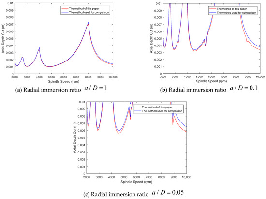
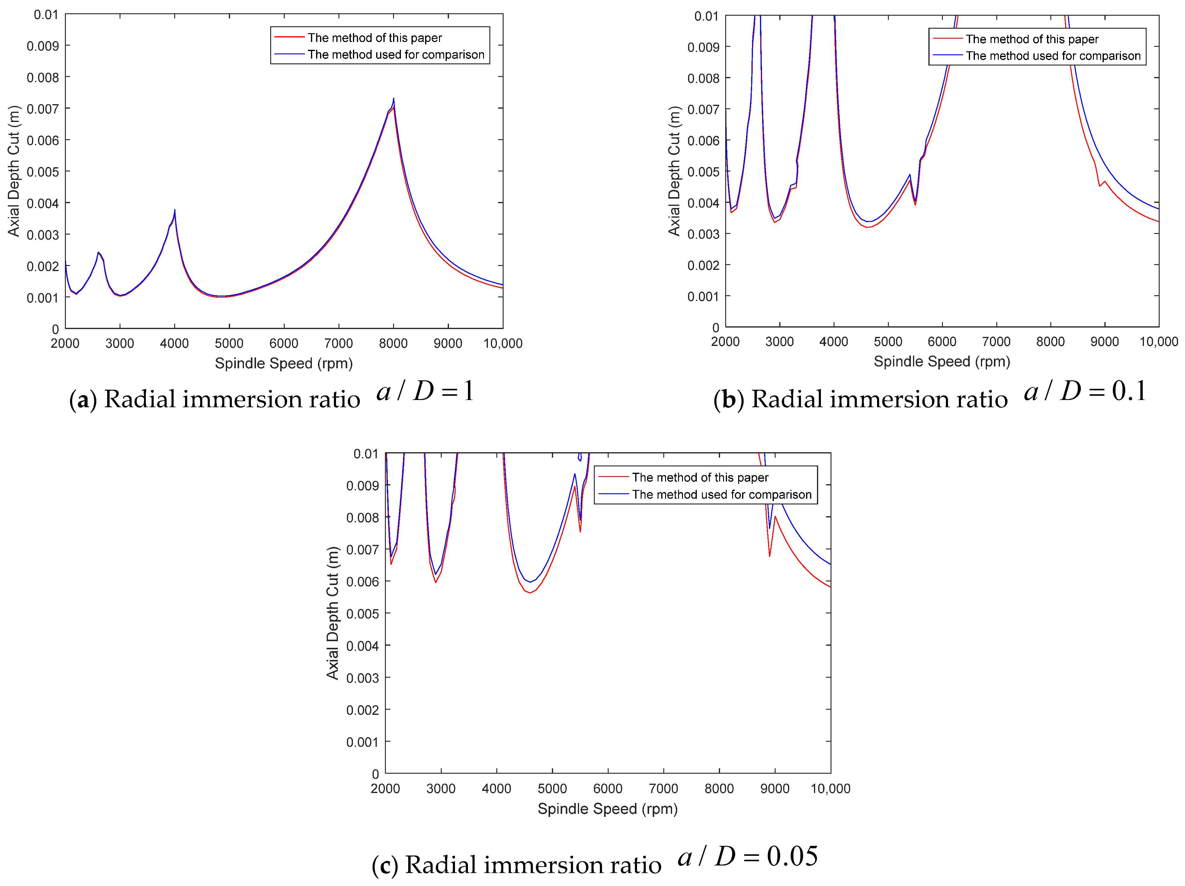
The parameters selected for the double-degree-of-freedom model are the same as those used in the single-degree-of-freedom milling model. Figure 2 lists the stability diagrams for both methods under radial immersion ratios of 1, 0.1, and 0.05. As can be seen from Figure 2, under different radial immersion ratios, the change trend of axial depth cut with the increase in spindle speed is basically the same as that of the reference method, indicating that the calculation results of the two methods are basically the same regardless of the size of the radial immersion ratio. It shows again that the method proposed in this paper is basically consistent with the results of the reference method, which proves that the method proposed in this paper ensures the accuracy of the calculation.

Figure 2.
Comparison of double-degree-of-freedom milling model at different immersion ratios [16].
Table 2 presents the computation times for different methods. As shown in Table 2, under the same parameters, the method proposed in this paper reduces computation time by about 13–18%.

Table 2.
Computational time comparison of double-degree-of-freedom milling model at different immersion ratios.
These results further demonstrate that the method proposed in this paper improves computational efficiency while ensuring calculation accuracy.
6. Conclusions and Future Works
This paper proposes an improved full-discretization algorithm specifically for the processing of spiral bevel gears, which is utilized to predict the stability of delayed cutting during the milling process. Considering the regenerative effects in milling, the dynamic response of the process is described using a linear time-periodic system with multiple time delays. The algorithm is validated using both single- and double-degree-of-freedom milling models, and its correctness is confirmed through comparison with previous studies.
Under the same computational parameters, the new method reduces computation time by 13–21% compared to previous methods while ensuring calculation accuracy.
This paper focuses on the prediction of time-lagged cutting stability in the milling process of spiral bevel gears by the full-discrete method. In the future, attention should be paid to the application of the full-discrete method in a more suitable way to the actual machining process, such as the cutting stability prediction for different machine structures and different machining environments.
Author Contributions
Conceptualization, C.T. and Y.T.; Methodology, C.T.; Investigation, T.W.; Writing—original draft, C.T.; Writing—review & editing, T.W.; Supervision, Y.T.; Project administration, Y.T.; Funding acquisition, T.W. All authors have read and agreed to the published version of the manuscript.
Funding
This work was supported by the National Natural Science Foundation of China [Grant No. 51975407] and National Key R&D Program (Industrial Software) [2022YFB3303601].
Data Availability Statement
The data presented in this study are available on request from the corresponding author.
Conflicts of Interest
The authors declare no conflict of interest.
References
- Smith, S.; Tlusty, J. Efficient Simulation Programs for Chatter in Milling. CIRP Ann. 1993, 42, 463–466. [Google Scholar] [CrossRef]
- Sridhar, R.; Hohn, R.E.; Long, G.W. A stability algorithm for the general milling process. ASME J. Eng. Ind. 1968, 90, 330–334. [Google Scholar] [CrossRef]
- Minis, I.; Yanushevsky, R. A new theoretical approach for the prediction of machine tool chatter in milling. J. Eng. Ind. 1993, 115, 1–8. [Google Scholar] [CrossRef]
- Altintas, Y.; Budak, E. Analytical prediction of stability lobes in milling. CIRP Ann. Manuf. Technol. 1995, 44, 357–362. [Google Scholar] [CrossRef]
- Yang, W.A.; Huang, C.; Cai, X.; You, Y. Effective and fast prediction of milling stability using a precise integration-based third-order full-discretization method. Int. J. Adv. Manuf. Technol. 2020, 106, 4477–4498. [Google Scholar] [CrossRef]
- Ji, Y.; Wang, X.; Liu, Z.; Wang, H.; Jiao, L.; Zhang, L.; Huang, T. Stability prediction with simultaneously considering the multiple factors coupling effects-regenerative effect, mode coupling, and process damping. Int. J. Adv. Manuf. Technol. 2018, 97, 2509–2527. [Google Scholar] [CrossRef]
- Dai, Y.B.; Li, H.; Liu, B.; Yang, C. Calculation boundary vulnerability of numerical algorithm in milling stability prediction. Int. J. Adv. Manuf. Technol. 2022, 119, 8271–8286. [Google Scholar] [CrossRef]
- Shi, Z.; Liu, L.; Liu, Z.; Zhang, X. Frequency-domain stability lobe prediction for high-speed face milling process under tool-workpiece dynamic interaction. Proc. Inst. Mech. Eng. Part B J. Eng. Manuf. 2016, 231, 2336–2346. [Google Scholar] [CrossRef]
- Zhang, C.; Yan, Z.; Jiang, X. Numerical integration scheme–based semi-discretization methods for stability prediction in milling. Int. J. Adv. Manuf. Technol. 2021, 115, 397–411. [Google Scholar] [CrossRef]
- Ding, Y.; Zhu, L.M.; Zhang, X.J.; Ding, H. Second-order full-discretization method for milling stability prediction. Int. J. Mach. Tools Manuf. 2010, 50, 926–932. [Google Scholar] [CrossRef]
- Cheng-Ying, L.; Jie, Z.; Wei, L.; Zhi, Z. A Full-discretization Method for Milling Stability Predication Based on Time-step Control. Modul. Mach. Tool Autom. Manuf. Tech. 2017, 12, 59–61. [Google Scholar]
- Ding, Y.; Zhu, L.; Zhang, X.; Ding, H. A full-discretization method for prediction of milling stability. Int. J. Mach. Tools Manuf. 2010, 50, 502–509. [Google Scholar] [CrossRef]
- Sellmeier, V.; Denkena, B. Stable islands in the stability chart of milling processes due to unequal tooth pitch. Int. J. Mach. Tools Manuf. 2011, 51, 152–164. [Google Scholar] [CrossRef]
- Sims, N.; Mann, B.; Huyanan, S. Analytical prediction of chatter stability for variable pitch and variable helix milling tools. J. Sound Vib. 2008, 317, 664–686. [Google Scholar] [CrossRef]
- Quintana, G.; Ciurana, J.; Ferrer, I.; Rodrı´guez, C.A. Sound mapping for identification of stability lobe diagrams in milling processes. Int. J. Mach. Tools Manuf. 2009, 49, 203–211. [Google Scholar] [CrossRef]
- Jin, G.; Qi, H.J.; Cai, Y.J.; Zhang, Q.C. Stability prediction for milling process with multiple delays using an improved semi- discretization method. Math. Methods Appl. Sci. 2015, 39, 949–958. [Google Scholar] [CrossRef]
- Ozoegwu, C.G. High order vector numerical integration schemes applied in state space milling stability analysis. Appl. Math. Comput. 2016, 273, 1025–1040. [Google Scholar] [CrossRef]
- Merdol, D.S. Virtual Three-Axis Milling Process Simulation and Optimization. Ph.D. Thesis, University of British Columbia, Vancouver, BC, Cananda, 2008. [Google Scholar]
- Jin, G.; Zhang, Q.; Hao, S.; Xie, Q. Stability prediction of milling process with variable pitch cutter. Math. Probl. Eng. 2013, 2013, 932013. [Google Scholar] [CrossRef]
- Jin, G.; Zhang, Q.; Hao, S.; Xie, Q. Stability prediction of milling process with variable pitch and variable helix cutters. Proc. Inst. Mech. Eng. Part C J. Mech. Eng. Sci. 2014, 228, 281–293. [Google Scholar] [CrossRef]
- Dai, Y.; Li, H.; Xing, X.; Hao, B. Prediction of chatter stability for milling process using precise integration method. Precis. Eng. 2017, 52, 152–157. [Google Scholar] [CrossRef]
Disclaimer/Publisher’s Note: The statements, opinions and data contained in all publications are solely those of the individual author(s) and contributor(s) and not of MDPI and/or the editor(s). MDPI and/or the editor(s) disclaim responsibility for any injury to people or property resulting from any ideas, methods, instructions or products referred to in the content. |
© 2024 by the authors. Licensee MDPI, Basel, Switzerland. This article is an open access article distributed under the terms and conditions of the Creative Commons Attribution (CC BY) license (https://creativecommons.org/licenses/by/4.0/).


