
Decentralized Adaptive Event-Triggered Fault-Tolerant Cooperative Control of Multiple Unmanned Aerial Vehicles and Unmanned Ground Vehicles with Prescribed Performance under Denial-of-Service Attacks

Abstract
:1. Introduction
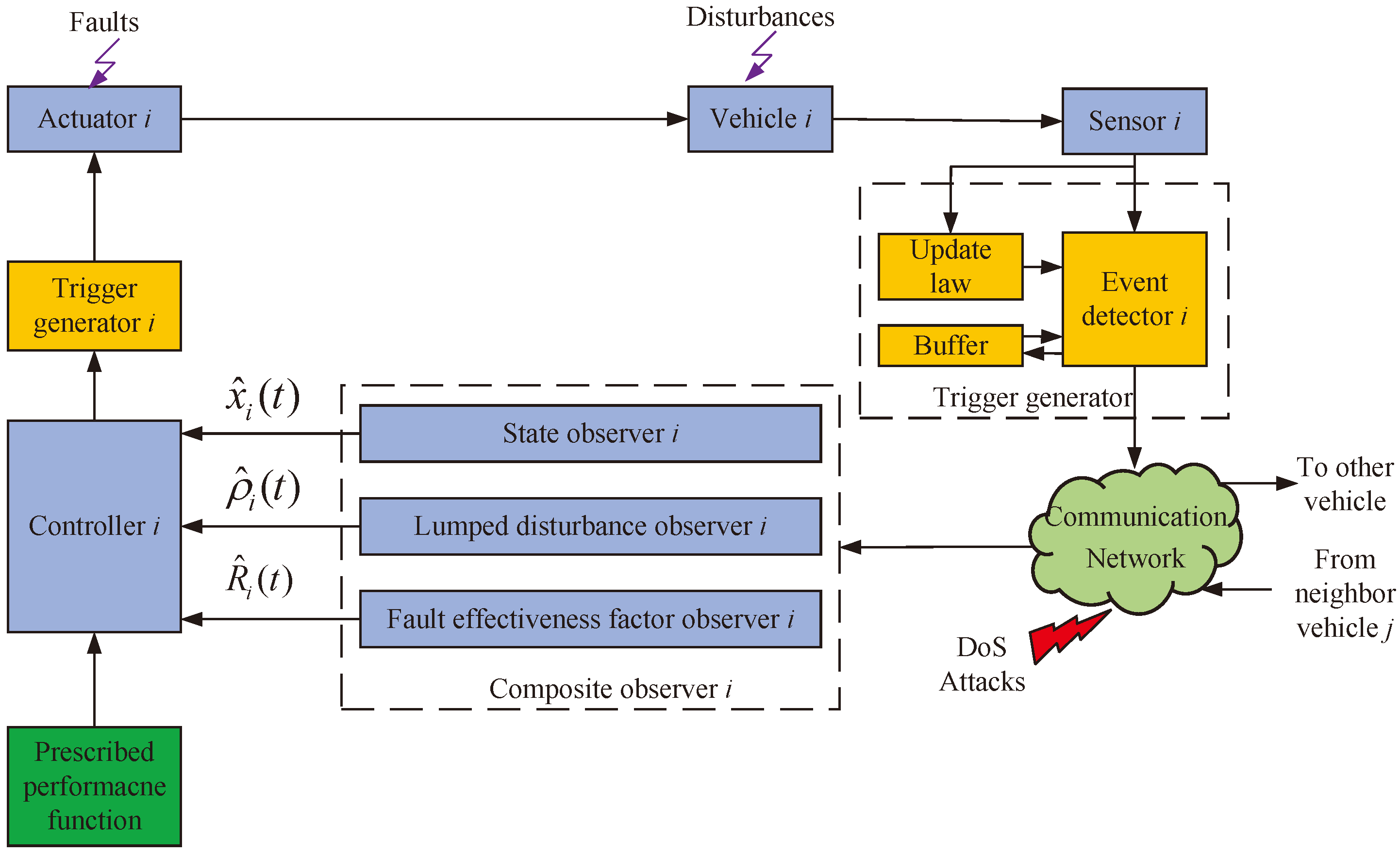
- In order to save the limited communication network resources, the novel ET mechanism is illustrated, in comparison with some existing results [28,29], in which only the ET mechanism in the control channel is considered. The event-triggered mechanism is also presented by using the triggered state directly, which may cause chattering of the controller once actuator faults or DoS attacks occur. In this work, the ET mechanism in the sensor and controller channel are both considered. The presented ET mechanism can balance the limited communication network resources and information utilization. Furthermore, the Zeno behavior is excluded.
- The composite observer is presented, in which the state is estimated and the lumped disturbances are reconstructed utilizing the estimated state and the sensor channel triggered outputs without using the disturbance upper bound. In this way, the unknown variables are estimated with less information. In contrast to some existing results [30,31], in which the upper bound information of disturbances should be known when designing the disturbance observer, the results of this work provide another method to estimate the disturbances.
- An observer-based ET-FTCC scheme, including FTC compensation, disturbances degradation, and DoS prevention components, is studied. To obtain good system performance, a modified PPF is presented to convert the tracking errors, thereby relaxing the requirement for the exact initial conditions. In contrast to the work in [32], in which the control input is blocked when the DoS attack is active, the data at the instant when the attacker is switched between asleep and active in this work is triggered and utilized as a compensation component.
2. Preliminaries
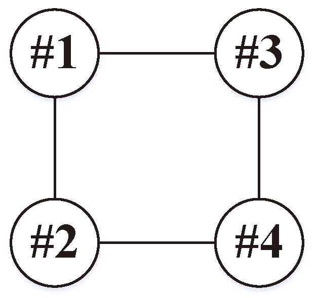
2.1. Graph Theory
2.2. Actuator Fault Model
2.3. DoS Attack Model
3. Problem Formulation
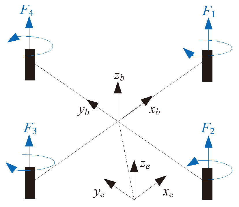
3.1. UAV Dynamics
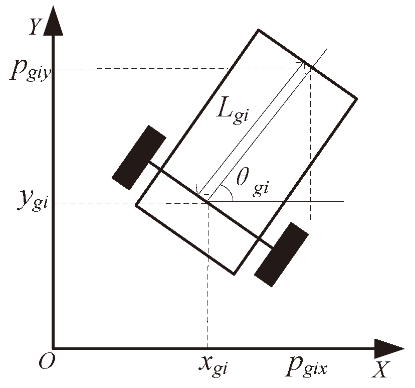
3.2. UGV Dynamics
3.3. Model Transformation
3.4. Control Objective
4. Main Results
4.1. Event-Triggered Mechanism Design
4.2. Observer Design
4.3. FTCC Design
5. Simulation Studies
5.1. Simulation Conditions
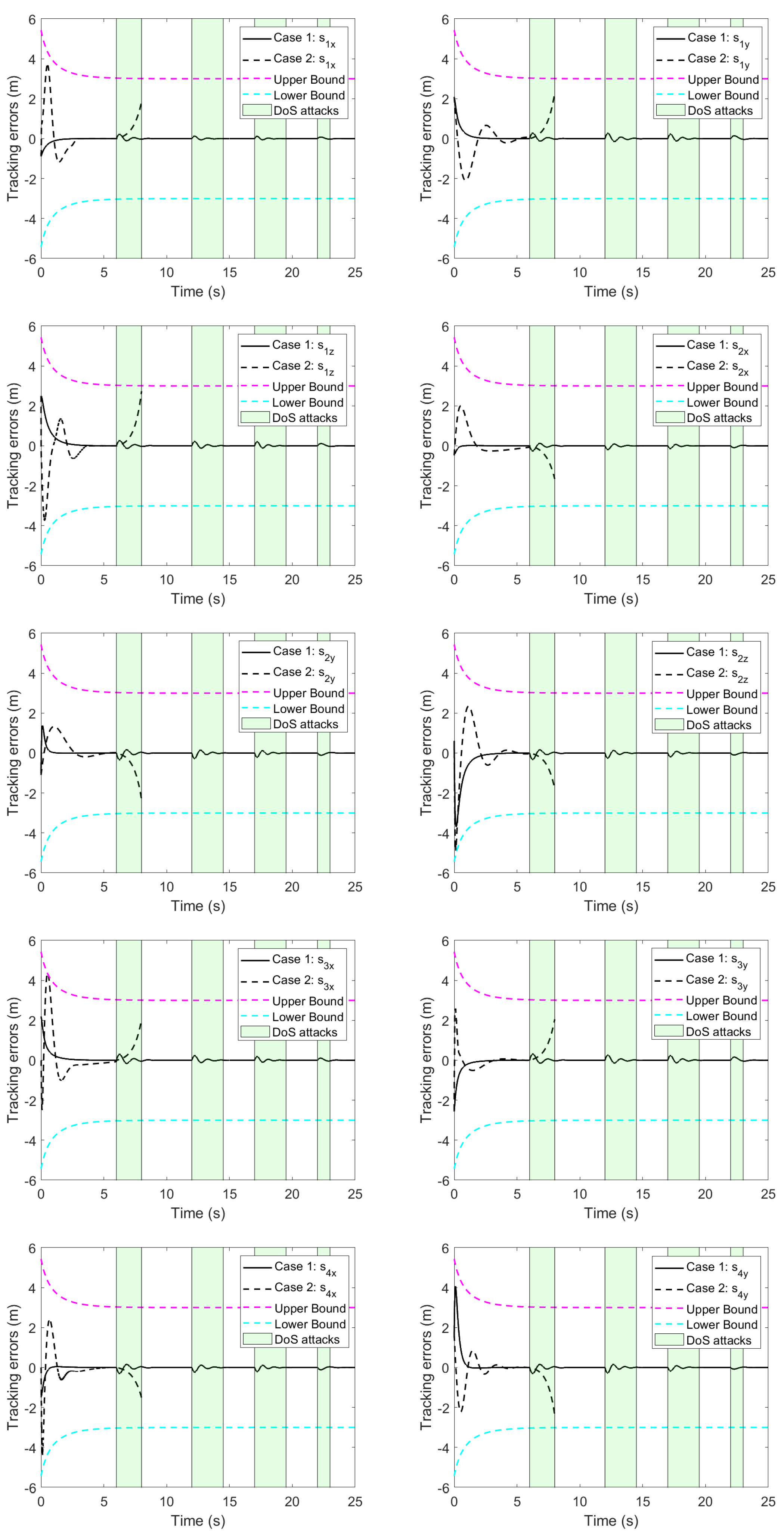
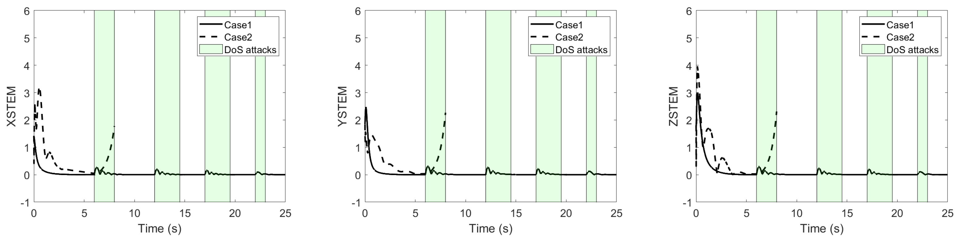
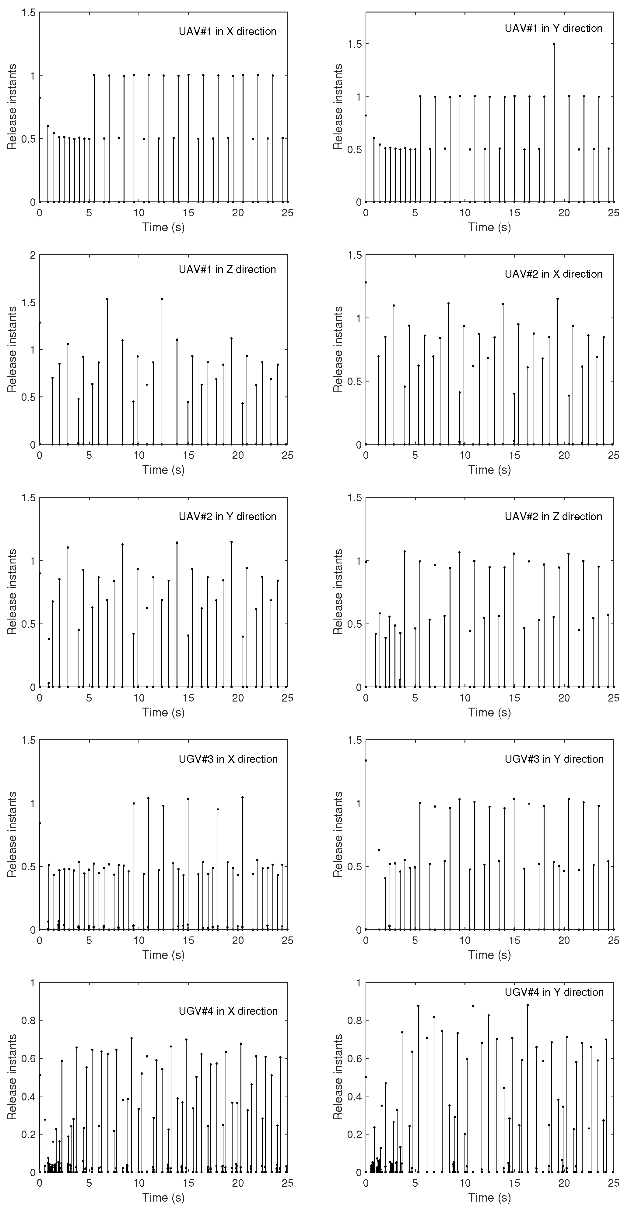
5.2. Simulation Results
6. Conclusions
Author Contributions
Funding
Data Availability Statement
Conflicts of Interest
References
- Liu, C.; Jiang, B.; Wang, X.; Yang, H.; Xie, S. Distributed Fault-Tolerant Consensus Tracking of Multi-Agent Systems under Cyber-Attacks. IEEE/CAA J. Autom. Sin. 2022, 9, 1037–1048. [Google Scholar] [CrossRef]
- Zuo, Z.; Cao, X.; Wang, Y.; Zhang, W. Resilient Consensus of Multiagent Systems Against Denial-of-Service Attacks. IEEE Trans. Syst. Man Cybern. Syst. 2022, 52, 2664–2675. [Google Scholar] [CrossRef]
- Shen, Q.; Jiang, B.; Shi, P. Adaptive Fault Diagnosis for T–S Fuzzy Systems with Sensor Faults and System Performance Analysis. IEEE Trans. Fuzzy Syst. 2014, 22, 274–285. [Google Scholar] [CrossRef]
- Wu, J.; Cui, P. Cooperative Adaptive Fuzzy Control for the Synchronization of Nonlinear Multi-Agent Systems under Input Saturation. Mathematics 2024, 12, 1426. [Google Scholar] [CrossRef]
- Guo, X.; Wang, C.; Dong, Z.; Ding, Z. Adaptive Containment Control for Heterogeneous MIMO Nonlinear Multiagent Systems With Unknown Direction Actuator Faults. IEEE Trans. Autom. Control 2023, 68, 5783–5790. [Google Scholar] [CrossRef]
- Liu, Y.; Su, H. Second-Order Consensus for Multiagent Systems with Switched Dynamics and Sampled Position Data. IEEE Trans. Syst. Man Cybern. Syst. 2022, 52, 4129–4137. [Google Scholar] [CrossRef]
- Jiang, B.; Shen, Q.; Shi, P. Neural-networked adaptive tracking control for switched nonlinear pure-feedback systems under arbitrary switching. Automatica 2015, 61, 119–125. [Google Scholar] [CrossRef]
- Jiang, B.; Zhang, K.; Shi, P. Integrated Fault Estimation and Accommodation Design for Discrete-Time Takagi-Sugeno Fuzzy Systems With Actuator Faults. IEEE Trans. Fuzzy Syst. 2011, 19, 291–304. [Google Scholar] [CrossRef]
- Chen, K.; Gu, Y.; Lin, H.; Zhang, Z.; Zhou, X.; Wang, X. Guaranteed Performance Event-Triggered Adaptive Consensus Control for Multiagent Systems under Time-Varying Actuator Faults. Mathematics 2024, 12, 1528. [Google Scholar] [CrossRef]
- Wu, Y.; Li, J.; Liu, L.; Wu, C. Distributed adaptive practical formation tracking for multi-agent systems with actuator faults. Int. J. Robust Nonlinear Control 2023, 33, 1633–1654. [Google Scholar] [CrossRef]
- Wang, Z.; Wu, Y.; Liu, L.; Zhang, H. Adaptive Fault-Tolerant Consensus Protocols for Multiagent Systems with Directed Graphs. IEEE Trans. Cybern. 2020, 50, 25–35. [Google Scholar] [CrossRef] [PubMed]
- Xiao, S.; Dong, J. Distributed Adaptive Fuzzy Fault-Tolerant Containment Control for Heterogeneous Nonlinear Multiagent Systems. IEEE Trans. Syst. Man Cybern. Syst. 2022, 52, 954–965. [Google Scholar] [CrossRef]
- Wang, J.; Gui, Z.; Sun, J.; Xie, X.; Meng, Q. Distributed Fault-Tolerant Control of Nonlinear Multiagent Systems With Generally Uncertain Semi-Markovian Switching Topologies. IEEE Trans. Autom. Sci. Eng. 2024. [Google Scholar] [CrossRef]
- Zhao, L.; Zhao, F.; Che, W.W. Distributed adaptive fuzzy fault-tolerant control for multi-agent systems with node faults and denial-of-service attacks. Inf. Sci. 2023, 631, 385–395. [Google Scholar] [CrossRef]
- Deng, C.; Wen, C. Distributed Resilient Observer-Based Fault-Tolerant Control for Heterogeneous Multiagent Systems Under Actuator Faults and DoS Attacks. IEEE Trans. Control Netw. Syst. 2020, 7, 1308–1318. [Google Scholar] [CrossRef]
- Zhang, D.; Liu, L.; Feng, G. Consensus of Heterogeneous Linear Multiagent Systems Subject to Aperiodic Sampled-Data and DoS Attack. IEEE Trans. Cybern. 2019, 49, 1501–1511. [Google Scholar] [CrossRef]
- Wan, Y.; Wen, G.; Yu, X.; Huang, T. Distributed Consensus Tracking of Networked Agent Systems Under Denial-of-Service Attacks. IEEE Trans. Syst. Man Cybern. Syst. 2021, 51, 6183–6196. [Google Scholar] [CrossRef]
- Pan, K.; Lyu, Y.; Pan, Q. Adaptive Formation for Multiagent Systems Subject to Denial-of-Service Attacks. IEEE Trans. Circuits Syst. I 2022, 69, 3391–3401. [Google Scholar] [CrossRef]
- Lu, L.T.; Zhu, S.L.; Wang, D.M.; Han, Y.Q. Distributed adaptive fault-tolerant control with prescribed performance for nonlinear multiagent systems. Commun. Nonlinear Sci. 2024, 138, 108222. [Google Scholar] [CrossRef]
- Gao, Z.; Zhang, Y.; Guo, G. Finite-Time Fault-Tolerant Prescribed Performance Control of Connected Vehicles with Actuator Saturation. IEEE Trans. Veh. Technol. 2023, 72, 1438–1448. [Google Scholar] [CrossRef]
- Zhang, L.; Che, W.W.; Chen, B.; Lin, C. Adaptive Fuzzy Output-Feedback Consensus Tracking Control of Nonlinear Multiagent Systems in Prescribed Performance. IEEE Trans. Cybern. 2023, 53, 1932–1943. [Google Scholar] [CrossRef] [PubMed]
- Ding, Z.; Wang, H.; Sun, Y.; Qin, H. Adaptive prescribed performance second-order sliding mode tracking control of autonomous underwater vehicle using neural network-based disturbance observer. Ocean Eng. 2022, 260, 111939. [Google Scholar] [CrossRef]
- Gong, J.; Jiang, B.; Ma, Y.; Mao, Z. Distributed Adaptive Fault-Tolerant Formation-Containment Control with Prescribed Performance for Heterogeneous Multiagent Systems. IEEE Trans. Cybern. 2023, 53, 7787–7799. [Google Scholar] [CrossRef] [PubMed]
- Mousavian, M.; Atrianfar, H. Resilient Event-triggered Containment Control of Multi-Agent Systems under Asynchronous DoS Attacks and Disturbances. IEEE Trans. Control Netw. Syst. 2024. [Google Scholar] [CrossRef]
- Cheng, Z.; Yue, D.; Hu, S.; Ge, H.; Chen, L. Distributed event-triggered consensus of multi-agent systems under periodic DoS jamming attacks. Neurocomputing 2020, 400, 458–466. [Google Scholar] [CrossRef]
- Tang, Y.; Zhang, D.; Shi, P.; Zhang, W.; Qian, F. Event-Based Formation Control for Nonlinear Multiagent Systems Under DoS Attacks. IEEE Trans. Autom. Control 2021, 66, 452–459. [Google Scholar] [CrossRef]
- Ye, D.; Yang, X. Distributed event-triggered consensus for nonlinear multi-agent systems subject to cyber attacks. Inf. Sci. 2019, 473, 178–189. [Google Scholar] [CrossRef]
- Liu, Y.; Jia, Y. Event-triggered consensus control for uncertain multi-agent systems with external disturbance. Int. J. Syst. Sci. 2019, 50, 130–140. [Google Scholar] [CrossRef]
- Li, J.; Yang, Z.; Mu, X.; Wu, X. Passivity-based Event-triggered Fault Tolerant Control for Nonlinear Networked Control System with Actuator Failures and DoS Jamming Attacks. J. Franklin Inst. 2020, 357, 9288–9307. [Google Scholar] [CrossRef]
- Sun, L.; Zheng, Z. Disturbance Observer-Based Robust Saturated Control for Spacecraft Proximity Maneuvers. IEEE Trans. Control Syst. Technol. 2018, 26, 684–692. [Google Scholar] [CrossRef]
- He, W.; Sun, Y.; Yan, Z.; Yang, C.; Li, Z.; Kaynak, O. Disturbance Observer-Based Neural Network Control of Cooperative Multiple Manipulators With Input Saturation. IEEE Trans. Neural Netw. Learn. Syst. 2020, 31, 1735–1746. [Google Scholar] [CrossRef] [PubMed]
- Ma, X.; Yang, L.; Ma, L.; Dong, W.; Jin, M.; Zhang, L.; Yang, F.; Lin, Y. Consensus tracking control for uncertain non-strict feedback multi-agent system under cyber attack via resilient neuroadaptive approach. Int. J. Robust Nonlinear Control 2022, 32, 4251–4280. [Google Scholar] [CrossRef]
- Xiang, X.; Liu, C.; Su, H.; Zhang, Q. On decentralized adaptive full-order sliding mode control of multiple UAVs. ISA Trans. 2017, 71, 196–205. [Google Scholar] [CrossRef]
- Du, H.; Zhu, W.; Wen, G.; Duan, Z.; Lü, J. Distributed Formation Control of Multiple Quadrotor Aircraft Based on Nonsmooth Consensus Algorithms. IEEE Trans. Cybern. 2019, 49, 342–353. [Google Scholar] [CrossRef] [PubMed]
- Dong, X.; Hua, Y.; Zhou, Y.; Ren, Z.; Zhong, Y. Theory and Experiment on Formation-Containment Control of Multiple Multirotor Unmanned Aerial Vehicle Systems. IEEE Trans. Autom. Sci. Eng. 2019, 16, 229–240. [Google Scholar] [CrossRef]
- Aghaeeyan, A.; Abdollahi, F.; Talebi, H. UAV-UGVs cooperation: With a moving center based trajectory. Rob. Auton. Syst. 2015, 63, 1–9. [Google Scholar] [CrossRef]
- Lu, A.Y.; Yang, G.H. Input-to-State Stabilizing Control for Cyber-Physical Systems with Multiple Transmission Channels Under Denial of Service. IEEE Trans. Autom. Control 2018, 63, 1813–1820. [Google Scholar] [CrossRef]
- Xu, W.; Hu, G.; Ho, D.W.C.; Feng, Z. Distributed Secure Cooperative Control Under Denial-of-Service Attacks from Multiple Adversaries. IEEE Trans. Cybern. 2020, 50, 3458–3467. [Google Scholar] [CrossRef]
- Qin, J.; Ma, Q.; Gao, H.; Zheng, W.X. Fault-Tolerant Cooperative Tracking Control via Integral Sliding Mode Control Technique. IEEE/ASME Trans. Mechatronics 2018, 23, 342–351. [Google Scholar] [CrossRef]

Disclaimer/Publisher’s Note: The statements, opinions and data contained in all publications are solely those of the individual author(s) and contributor(s) and not of MDPI and/or the editor(s). MDPI and/or the editor(s) disclaim responsibility for any injury to people or property resulting from any ideas, methods, instructions or products referred to in the content. |
© 2024 by the authors. Licensee MDPI, Basel, Switzerland. This article is an open access article distributed under the terms and conditions of the Creative Commons Attribution (CC BY) license (https://creativecommons.org/licenses/by/4.0/).
Share and Cite
Liu, S.; Huang, J. Decentralized Adaptive Event-Triggered Fault-Tolerant Cooperative Control of Multiple Unmanned Aerial Vehicles and Unmanned Ground Vehicles with Prescribed Performance under Denial-of-Service Attacks. Mathematics 2024, 12, 2701. https://doi.org/10.3390/math12172701
Liu S, Huang J. Decentralized Adaptive Event-Triggered Fault-Tolerant Cooperative Control of Multiple Unmanned Aerial Vehicles and Unmanned Ground Vehicles with Prescribed Performance under Denial-of-Service Attacks. Mathematics. 2024; 12(17):2701. https://doi.org/10.3390/math12172701
Chicago/Turabian StyleLiu, Shangkun, and Jie Huang. 2024. "Decentralized Adaptive Event-Triggered Fault-Tolerant Cooperative Control of Multiple Unmanned Aerial Vehicles and Unmanned Ground Vehicles with Prescribed Performance under Denial-of-Service Attacks" Mathematics 12, no. 17: 2701. https://doi.org/10.3390/math12172701