Article

Mathematical Formulation and Numerical Simulation of the Mechanical Behavior of Ceramic/Metal (TiB/Ti) FG Sheets Subjected to Spherical Indenter

1
Laboratory of Electrochemistry and Environment (LEE), National Engineering School of Sfax, University of Sfax, Sfax 5080, Tunisia
2
Department of Technology, IPEIN, Carthage University, Carthage 1054, Tunisia
3
Department of Mechanical Engineering, College of Engineering, University of Ha’il, Ha’il City 2440, Saudi Arabia
*
Author to whom correspondence should be addressed.
Mathematics 2024, 12(2), 209; https://doi.org/10.3390/math12020209
Submission received: 9 November 2023 / Revised: 16 December 2023 / Accepted: 22 December 2023 / Published: 8 January 2024

Abstract

:
The main motivation for the present work is to provide an improved description of the response of Functionally Graded (FG) structures under a spherical indenter, considering material nonlinearities. This is achieved through the implementation of elastoplastic material behavior using integration points to avoid the division of the structure into multiple layers. The current paper proposes a numerical investigation into the mechanical response of functionally graded materials (FGMs) in contact with a rigid hemispherical head indenter. The numerical model considers both the Mori–Tanaka model and self-consistent formulas of Suquet to accurately model the smooth variation of material properties through the thickness of the elastoplastic FG material. The model execution involves a UMAT user material subroutine to implement the material behavior into ABAQUS/Standard. The user material UMAT subroutine is employed to introduce material properties based on the integration points, allowing for an accurate representation and analysis of the material’s behavior within the simulation. The developed numerical model is validated through a comparison with experimental results from the literature, showing a good correlation that proves the efficiency of the proposed model. Then, a parametric study is conducted to analyze the effect of the indenter dimension, the indentation depth and the gradient index on the indentation force, the contact pressure evolution, von Mises equivalent stress and equivalent plastic strain distributions located on the vicinity of the contact zone. The results showed that the elastoplastic response of TiB/Ti FG plates is significantly influenced by the gradient index, which determines the properties of the FG composite through the thickness. These results may help development engineers choose the optimal gradation for each industrial application in order to avoid contact damage.

1. Introduction

Functionally Graded Materials belong to the family of advanced composite materials that attract several promising industrial applications. FG sheets have been generally generated by combining at least two components from different materials in the form of particles by varying the constituent’s volume fractions. This specific combination leads to create a new material by varying the composition, microstructure and properties through a given direction of the structure and thus a variation in the mechanical behavior of the FG material. These advanced composite materials can be designed for a wide range of potential applications including innovative technologies. Furthermore, FGMs possess better resistance to indentation due to their tailored microstructure compared to a reference material, which is typically the bulk or base material from which the FGM is derived. By selecting materials with varying hardness or toughness, FG sheets can withstand external forces and deformations more effectively than conventional sheets.
Experimental tests performed on FG materials proved that these promising composite materials with their specific features present tailored properties compared to conventional mono-material [1,2,3]. Moreover, it is noteworthy that FG materials have addressed numerous interface problems encountered in multi-layered composite materials. This has led engineers to extensively employ FGMs in various industrial applications, including electronics, sensor technology, biomechanics, thermos-fluid applications, spacecraft structures, tribology applications, etc. [4,5,6]. Regarding the simulation exercises, mechanical properties such as material density, Young’s modulus, Poisson’s coefficient, and shear modulus are defined continuously as functions of the thickness of the FG sheet. In other words, the gradient of these input parameters depends on the position inside the material.
FGMs have been the subject of numerous studies and research in the field of materials science and engineering. For example, Kumar and Harsha [7] studied the static and free vibration response of hybrid FGM plates under thermal, electric, and mechanical loads. The results from the static and free vibration analyses indicate the prospective utilization of the functionally graded piezoelectric material plate. This material holds promise for applications in piezoelectric actuators and for sensing deflection in bimorph structures. In Jrad et al. [8] and Mallek et al. [9], the authors numerically investigated the response of FGM shells containing piezoelectric layers; it was found that the power-law index and the piezoelectric layer thickness have a major impact on the static response of the piezo-laminated FGM structure. Recently, there has been a growing focus among researchers on considering the effects of porosity in the analysis of functionally graded structures. As a result, porous FGMs have been subjected to numerical investigations under hygro-thermo-mechanical coupling loadings for buckling as well as static bending and buckling behaviors, as conducted by [10] and [11], respectively. Additionally, ref. [12] has numerically analyzed the thermodynamic behavior and service reliability of thermal protection systems employing bolted joints made of porous ZrO2/(ZrO2+Ni) functionally graded materials. Furthermore, ref. [13] has conducted a field distribution measurement of the residual stress in porous ZrO2/(ZrO2+Ni) ceramic–metal FGMs based on nano-indentation tests.
Moreover, many researchers have recently been investigating contact problem. It is interesting to note that the authors confirmed that the use of a suitable gradient of Young’s modulus could overcome the contact damage occurring in several tribology applications. For example, one can avoid conical cracking in Hertzian indentation [14], improving the wear resistance [15]. Zhang et al. [16] demonstrated that the gradient of Young’s modulus, loading condition and the geometry of the FG structure have a direct impact on the crack propagation and shape in FGM coatings. From a procedural point of view, most of the works present in the literature, which investigate contact problems for FGMs, are performed in a theoretical way. Indeed, FG structures have been investigated in numerous studies using various kinematic models [17] taking into account piezoelectric [18,19,20] and environmental effects [21,22].
In the meantime, macro-indentation tests are widely applied on an industrial scale to identify mechanical properties data of solid structures under significant loading, such as ceramics and aluminum, but not for their mixture like FGMs. Only a few developments in the literature are related to the impact response of FG plates or shells. Two behaviors were considered: linear [23] or nonlinear elastic [24] and elastoplastic [25,26]. Gunes et al. [27] studied the response of Al/SiC FG circular sheets subjected to low-velocity impact. The isotropic–elastic behavior is considered for the silicon carbide layer. However, the elastoplastic behavior is taken for the aluminum layer. In this work, the Tamura–Tomota–Ozawa model [28], referred as the TTO model, integrating J2 plasticity has been used to model the elastoplastic behavior of the composite material. Note that the TTO model is widely used in the literature to model the elastoplastic behavior of FGMs [29]. With this model, some references can be added: pressure vessels [30], elastoplastic buckling of rectangular FG sheets [31], and thin coatings behavior [32]. Along with the TTO model, other efficient theoretical solutions can be cited here: incremental methods [33], the second-order method [34] and the Artificial Neural Network (ANN) approach in Atrian et al. [35]. The asymptotic homogenization algorithm was employed for elastoplastic FGMs with pure elastic inclusions along with elastoplastic metallic matrix integration using the Ludwik hardening law [36]. This algorithm is implemented through ABAQUS software. Comparing this method with the mechanical homogenization one, based on the self-consistent methods [37], it appears that the different results are in concordance. However, asymptotic homogenization methods have a significant drawback, which is the increased computational time due to high computer hardware requirements. Consequently, the self-consistent formulas of Suquet are well applied, given their simplicity. While the self-consistent formulas of Suquet provide a straightforward and computationally efficient approach for the homogenization of heterogeneous materials, they also come with certain limitations. Firstly, the isotropic assumption implies that the method assumes material behavior is isotropic, potentially leading to inaccuracies in predicting anisotropic behaviors [38]. Secondly, the validity of the method may be compromised in the presence of strong heterogeneity, particularly when material properties vary significantly [39]. Additionally, the lack of microstructural detail limits the method’s ability to capture intricate features of the material’s internal structure.
The main objective of the present paper is to enhance the knowledge about the mechanical response behavior of FG structures subjected to a rigid indenter with a predefined geometry. Unlike other methods that rely on a multilayered division of the structure [25,27,40,41] to implement material properties of FGMs, this approach stands out by utilizing the coordinates of integration points. By implementing the FG material properties based on these coordinates, it successfully prevents stress discontinuity in the thickness direction of the structure, and a reduction in simulation time is achieved. The numerical model developed for this purpose takes into account the material’s nonlinearity. For the material behavior model implemented in ABAQUS/Standard via a UMAT user material, the gradient index, Mori–Tanaka model, and self-consistent formulas of Suquet are taken into account to model the smooth variation of elastoplastic material properties based on the ceramic volume fraction in the ceramic/metal composite.

2. Constitutive Model for Elastoplastic FGM

2.1. Effective Elastic Properties of FGM

Functional Graded Materials are characterized, in their structure design, by a gradation in the distribution of composition and mechanical properties over their volume or thickness. In the present investigation, the two FGM layers consist of nonhomogeneous materials. Hence, the ceramic/metallic TiB/Ti mixture is smoothly and continuously varied over the sheet thickness according to the following power-law distribution.
V c z =   1   1 2 z h k ;   V c z + V m z = 1
where:
  • V c : The ceramic volume fraction;
  • V m : The metal volume fraction;
  • H: Thickness of the structure;
  • k: The power-law index which describes the continuous gradation of material properties through the thickness of the FGM plate.
In this study, the elastoplastic behavior of ceramic-reinforced metal matrix FGMs is micromechanically modeled in FE simulation by integrating Mori–Tanaka model and self-consistent formulas of Suquet. According to the Mori–Tanaka model, the effective bulk modulus k(z) and the effective shear modulus G(z) of the components can be written as follows [42].
k z = k m 1 + V c k c a 1 k m 1 1 + V c 1 a 1 1 ; G z = G m 1 + V c G c b 1 G m 1 1 + V c 1 b 1 1
where a 1 and b 1 refer to:
a 1 = 1 + 1 + ν m 3 1 ν m k c k m 1   ; b 1 = 1 + 2 4 5 ν m 15 1 ν m G c G m 1
Using the mixture rule, both the Poisson’s ratio and the Young’s modulus will take the following forms:
ν z = 1 2 3 k z 2 G z 3 k z + G z ; E z = 2 G z 1 + ν z

2.2. Elastoplastic Stress–Strain Relation

The formulation of the complete elastoplastic numerical model given in this section to assess the response of the TiB/Ti FG structure is based on our previous works [42]. Plasticity models based on iterative calculations are written using the flow rule, the yield surface, and the homogenized expansion laws that give the formulation of the hardening behavior of the ceramic-reinforced metal matrix of the composite material. In this study, vectors are referred to using bold letters.
Elastic ε e and plastic ε p strains can be expressed:
ε = ε e   +   ε p
The elastic strain rate is expressed using the stress rate by
σ ˙ = D : ε ˙ e = D : ε ˙ ε ˙ p
D : The general elastic operator.
The yield surface concerning the plastic deformation can be formulated as follows:
f σ , r = φ σ σ p r = 0 , σ p r = σ Y + Q r
σ Y , Q and r refer to, respectively, the yield stress, the drag stress in isotropic hardening and the internal variable attributing to the isotropic hardening. Using the Von-Mises J2 plastic criterion with isotropic hardening, the function φ σ represents the equivalent stress and takes the following form.
φ σ = σ P = σ T   P   σ where   P   = 1 0.5 0.5 0 0 0 1 0.5 0 0 0 1 0 0 0 3 0 0 S y m 3 0 3
Hence, the plastic strain rate can be expressed using the following formula:
ε ˙ p     = γ ˙ f σ = γ ˙   n ; n   =   1 φ P   σ
n is the flow vector and γ ˙ is the plastic multiplier defined according to the loading/unloading terms given by:
γ ˙ 0 ; f 0 ; γ ˙ f = 0

2.3. Effective Elastoplastic Properties of the FGM

The FGM’s two phases are studied by assuming that the plastic deformation occurs only on the metallic on (matrix). The behavior of the ceramic phase is assumed to be in concordance with a linear elastic attitude when deformation occurs.
Plastic hardening law of Ludwik is used to reliably predict the effective properties of the metal matrix [32].
σ m = σ Y m + K m   r n m
  • σ Y m : The metal yield strength;
  • K m : Metal strength coefficient;
  • n m : Metal strain-hardening exponent;
  • r : The cumulated plastic strain.
To describe the elastoplastic response of the studied FGM, the same hardening law of Ludwik is considered.
σ p = σ Y + K   r n
  • σ Y : The effective yield strength;
  • K : The effective strength coefficient;
  • n: The effective strain hardening parameter of the studied ceramic/metal FGM.
Using the homogenization method and self-consistent model of Suquet, the effective elastoplastic coefficients of the TiB/Ti FG structure are expressed as follows.
σ Y = E E m σ Y m ; K   = K m 1 + V c 1 V c n ; n   = n m
The elastoplastic indentation behavior of the ceramic/metal FG structure is modeled adopting the formulated elastoplastic constitutive relations as it is described schematically in Figure 1.

2.4. Numerical Integration Scheme

The integration of Equation (5) gives the evolution equation as follows:
ε n + 1 p = ε n p +   Δ γ   n n + 1 n n + 1   =   1 φ n + 1 H   σ n + 1
Using the decomposition of strain shown in Equation (5) and the elasticity relation in Equation (6), we obtain the formulation for the stress tensor as follows:
σ n + 1 =   D ( ε n + 1   ε n + 1 P )
σ n + 1 =   σ t r i a l       Δ γ D · n n + 1 ,   σ t r i a l = σ n + D · Δ ε
And finally
σ n + 1 =   I c 1 · σ t r i a l ,   I c = I + u D H , u =   Δ γ φ n + 1
From Equations (7) and (17), the condition of algorithmic consistence is as follows:
f ( Δ γ ) = φ   ( σ Y + Q ( r ) ) = 0 ,         φ = σ t r i a l T ·   I c T · H   · I c 1 · σ t r i a l 1 / 2

2.5. Closed-Form Tangent Operator

Differentiating the plastic strain Equation (14) gives
d ε n + 1 P = H [ u d σ n + 1 + u 1 σ n + 1 d ( Δ γ ) ]
Differentiating the stress tensor Equation (15) gives
d σ n + 1 = D ( d ε n + 1 d ε n + 1 P )
Inserting Equation (19) in Equation (20) gives
[ I + u D H ] d σ n + 1 = D d ε n + 1 u 1 D H σ n + 1 d ( Δ γ )
Or, with Equation (17)
I c d σ n + 1 = D d ε n + 1 x d ( Δ γ )   with   x = D H x 1 ,   x 1 = u 1 σ n + 1
And Equation (22) became
d σ n + 1 = D * d ε n + 1 V 1 d ( Δ γ )   with   D * = I c 1 D   and   V 1 = I c 1 x
The differentiation of Equation (18) defining the consistency condition gives the final formula of the elastoplastic consistent tangent modulus expressed as follows:
d σ n + 1 d ε n + 1 n + 1 = D e p = D * 1 q   V 1 V 2       V 1 = D * P   x ,   V 2 = D c t n n + 1
q = α + n n + 1 T ·   V 1   and   α = Q ( r ) Δ γ
This formulation has been taken into account in developing the material behavior for the two constituents of the FGM structure investigated in this work. The material behavior model is implemented through a user material subroutine UMAT in ABAQUS Standard, as mentioned earlier. The UMAT incorporates an algorithm developed to simulate the present plasticity model, utilizing the fully implicit backward Euler integration. This integration scheme is commonly employed in elastoplastic numerical problems due to its unconditional stability.

3. Numerical Approach and Model Validation

3.1. Finite Element Model

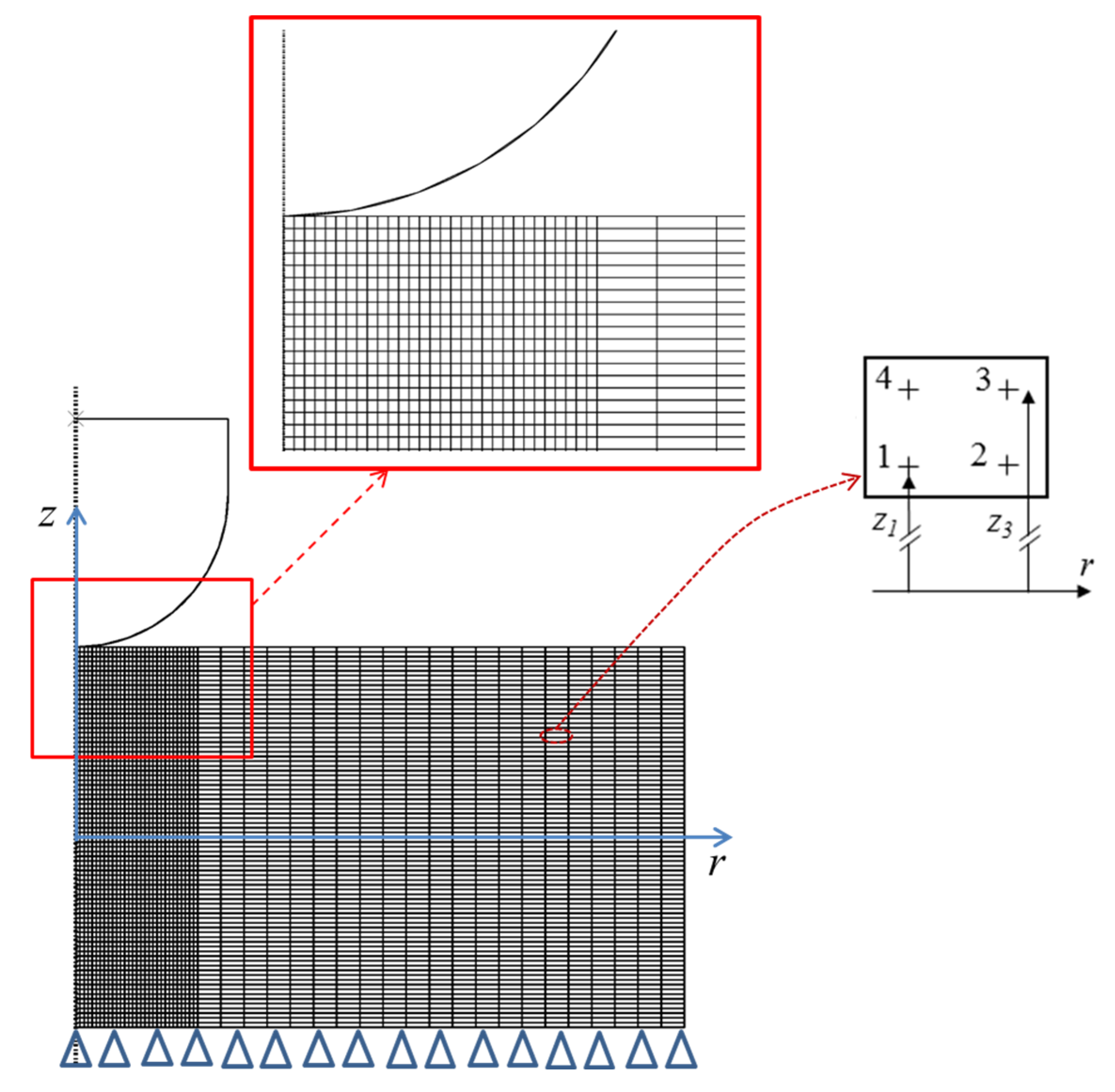
Figure 2 shows the axisymmetric model created through ABAQUS/Standard modeling. This specific model is employed to simulate the indentation process of a circular ceramic/metal (TiB/Ti) FG plate, with dimensions of 50 mm in diameter and 10 mm in thickness, subjected to a spherical rigid indenter. The contact between the elastoplastic composite plate and the indenter is assumed frictionless all over the contact interface. To adhere to the half-space assumption of the substrate, a rectangular specimen with a thickness of 10 mm and a length of 5 mm was selected. This ensures that for all loading and material conditions considered, both the contact radius-to-specimen thickness ratio and the contact radius-to-specimen length ratio remain below 0.1. The boundary conditions were simulated by incorporating a fixed support at the non-indented surface, thereby restricting the movement of nodes on this surface, as illustrated in Figure 2. The problem is treated as axisymmetric due to the homogeneous symmetry exhibited by the various elements. This facilitates the simplification of the 3D indentation problem into a 2D problem, resulting in reduced calculation time. Four nodes’ axisymmetric elements CAX4 are used to mesh the FG plate. A mesh sensitivity analysis is performed, focusing on the expected contact pressure variations near the contact zone at the end of the indentation act. It is observed that the expected stress remains constant when the mesh size is equal to or less than 0.02 mm in the vicinity of the contact zone. The indenter is assumed to be rigid, featuring a variable radius R with a pilot reference point. The boundary conditions for this reference point involve fixing it in all directions except allowing sliding along the normal vector to the FGM plate. To define the contact between the indenter and the FGM plate firstly, a “Hard contact” law is chosen; then, a “surface-to-surface” condition is selected to define the sliding formulation used for the contact interactions. A numerical simulation is conducted with the ABAQUS commercial software to analyze the elastoplastic indentation response of TiB/Ti FG circular plates. To mitigate stress-discontinuity issues arising from the modeling of multi-layered structures, the UMAT subroutine is incorporated into ABAQUS. This subroutine defines material properties based on the coordinates of the integration points, as illustrated in Figure 2. The UMAT subroutine interface is employed to implement the elastoplastic mechanical behavior across the thickness using the integration points. Figure 3 provides a better explanation of material implementation methodology.

3.2. Model validation

With the aim of assessing the efficiency and accuracy of the numerical model described in the previous section, it is important to compare the FE model prediction with the experimental results found in the literature. It is important to mention here that there are few experimental investigations on FGM plates that have undergone indentation phenomena in the literature. After a deep analysis of the literature, it seems that the work presented by Atrian et al. [35] can be a good reference for our work. In fact, the authors investigated experimentally some indentation tests to obtain the tensile stress–strain curve of Al7075-SiC material. The elastoplastic material properties of Al7075 taken from this work are as follows: E = 16 GPa, ν = 0.3 and σ Y = 105 MPa. The spherical indenter has a 0.5 mm diameter.
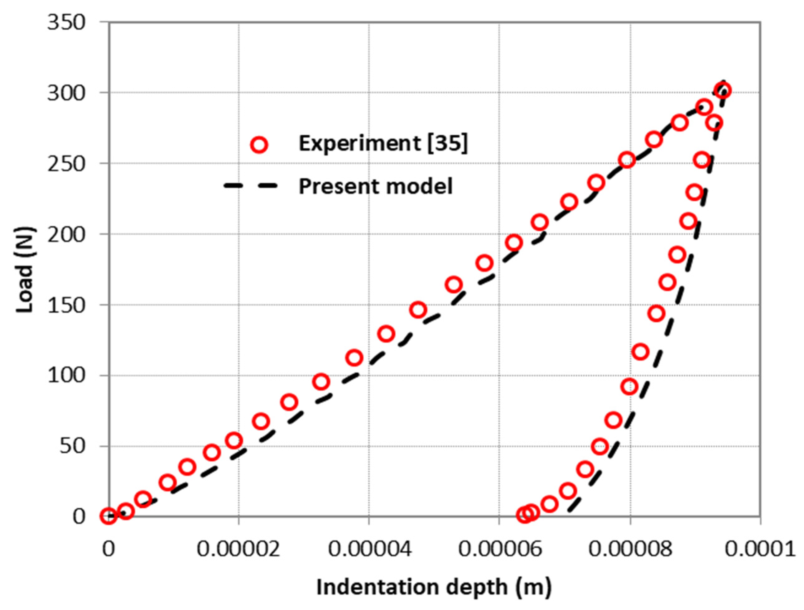
To verify the accuracy of our numerical model, all these parameters are introduced to the FE model, after the simulation results of the indentation, the load–depth is compared versus the experimental curve presented by Atrian et al. [35]. Figure 4 shows this comparison between numerical and experimental response to the indentation in terms of load–depth curve. Analyzing this figure, it is observed that the strength of the material increases when the indentation depth decreases. A similar effect is denoted also for the curvature of the loading curve.
A global analysis of the curves plotted in Figure 4 indicate that the numerical elastoplastic indentation response and the experimental result of Atrian et al. [35] are in good correlation. This may confirm the efficiency and the accuracy of the FE model used in the present work to predict the indentation response of ceramic/metallic FGM plates. In fact, this model can anticipate the maximum contact load and the residual indentation depth.

4. Numerical Results and Discussions

As mentioned previously, the main purpose of this numerical study is to investigate the indentation loading response of elastoplastic ceramic/metal FG sheet plates. The elastoplastic constitutive relations described in Section 2 have been implemented into ABAQUS/standard via a UMAT user-defined material subroutine. Several numerical simulations of indentation tests are conducted to assess the accuracy of the proposed model, initiating a parametric study with the primary objective of enhancing the understanding of the behavior of the circular titanium monoboride/titanium (TiB/Ti) Functionally Graded plate. Table 1 shows the elastoplastic properties of this material.
Aiming to analyze the elastoplastic behavior of the FG circular plate indented with a stiff indenter, a parametric study is considered based on two types of input parameters: geometrical parameters and material parameters. Mainly, the effect of the indenter head radius and gradient index is examined concerning the load–indentation depth curve, contact pressure dispersion, von Mises stress distributions and displacement beneath the indenter. Three indenter radii are considered: R = 0.2; 0.5 and 1 mm. During the simulations, the rigid indenter is subjected to a vertical displacement (which is the only movement) d = 0.1 and 0.2 mm. The gradient index values used in the material phase’s gradation are k = 0.5; 2; 4; 6 and 10. Table 2 draws the maximum of indentation load measured for these input parameters.
Analyzing this table, it is observable that when the indenter displacement d is doubled, with the same indenter R = 1 mm, the indentation force rise up approximately three times with the increase in the gradient index. In fact, the increase in the vertical displacement of the indenter will maximize the contact surface; the indenter head will be more emerged on the graded substrate, which increases the load needed to indent the FG plate.

4.1. The Gradient Index Effect

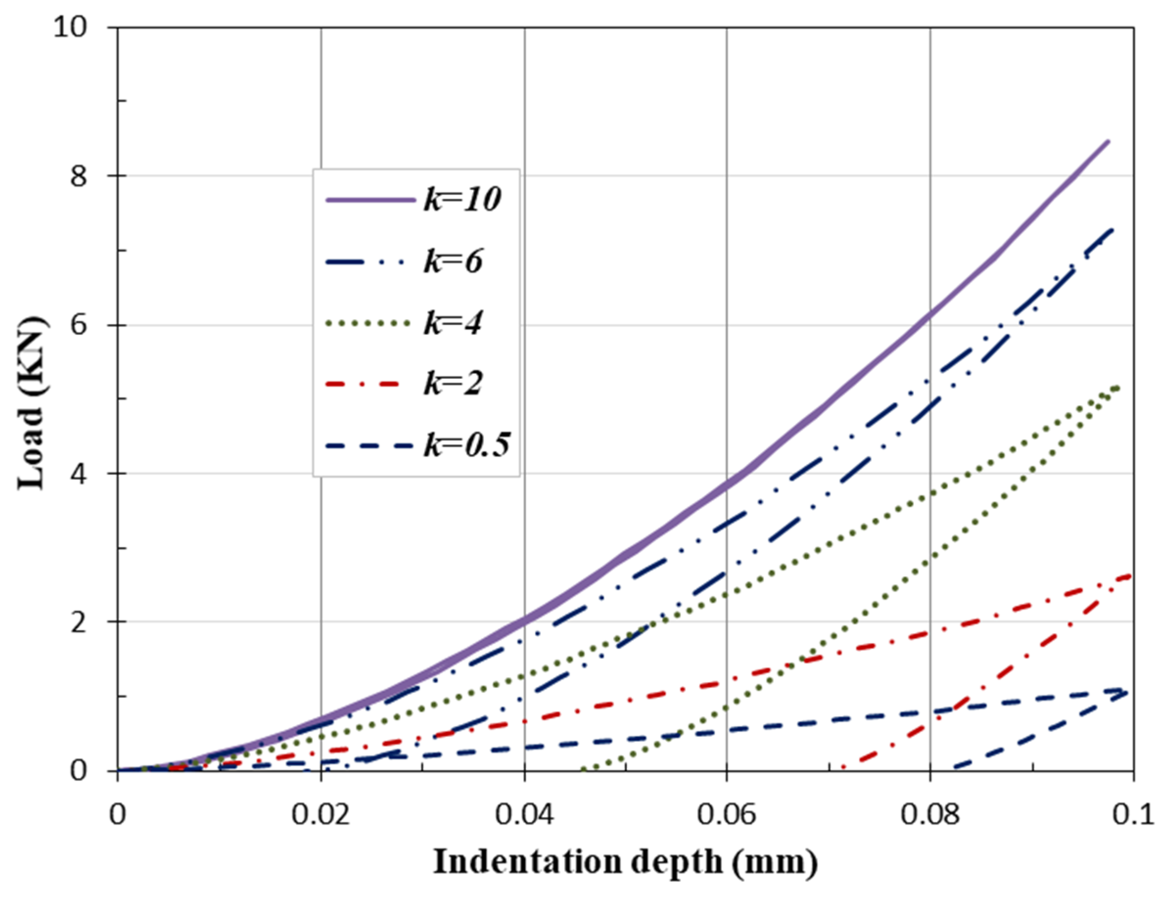
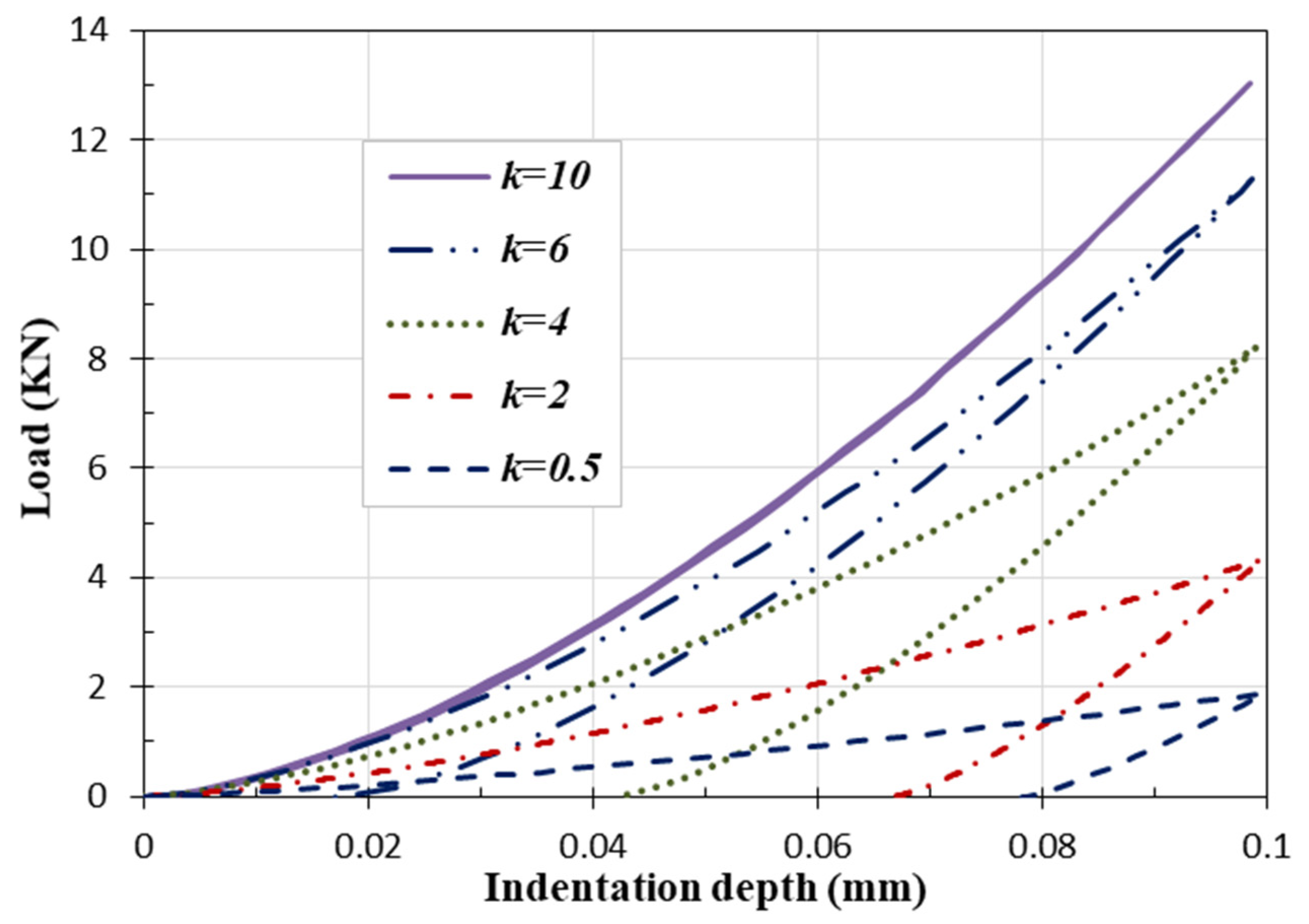
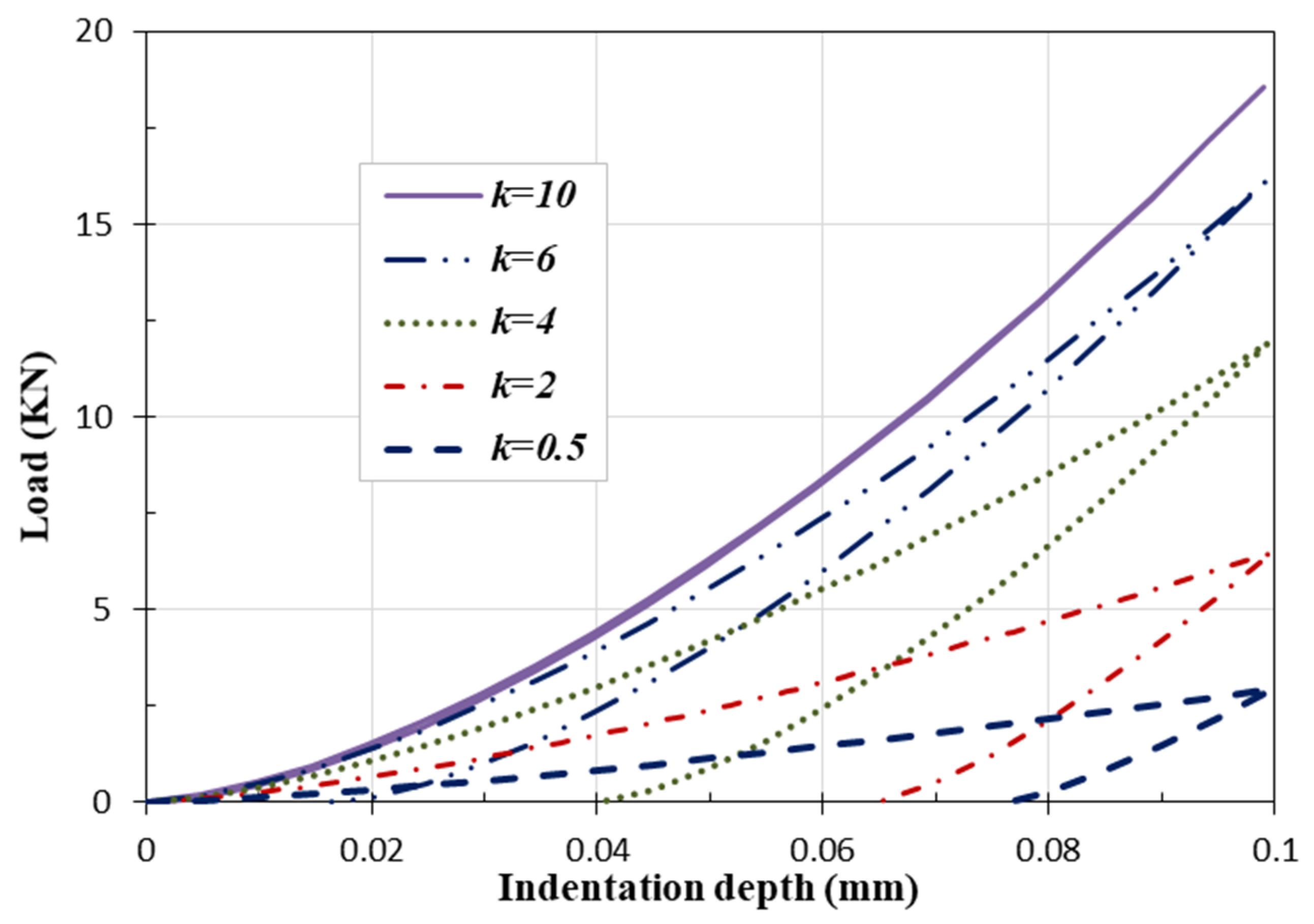
The present section analyzes the effect of the material gradation on the indentation response of the elastoplastic TiB/Ti plate. Figure 5, Figure 6, Figure 7 and Figure 8 depict the load to indentation depth curves considering the variable material gradient index.
From the results shown in Figure 5, Figure 6 and Figure 7 and summarized in Table 2, it can be noted that the rise of the gradient index pushes up the indentation force, which can be explained by the increase in the material stiffness as the effective Young’s modulus increases (see Equation (4)). Therefore, the FG plate needs more effort to be deformed as the elastic modulus of the substrate increases.
For a given indentation depth, as the diameter of the indenter decreases, the contact area is correspondingly reduced. This reduction in contact area leads to a decrease in the applied force. Consequently, the penetration of the indenter into the material becomes progressively easier as the contact area decreases.
For a given indentation depth and indenter radius, an increase in the material gradation index results in increased material hardness. This, in turn, necessitates a higher indentation force for a given indentation depth. Moreover, an elevated material gradation index implies a higher ceramic content in the Functionally Graded Material, which reduces the enclosed loop between loading and unloading paths, leading to an elastic response at higher values of k (k = 10). The gradient index has a significant impact on the elastoplastic indentation response of the FG plate in terms of the penetration tendency of the spherical indenter. Indeed, the springback phenomenon can be clearly observed with the augmentation of the gradient index. A typical elastic behavior is denoted for a gradient index of 10, which can be explained by the increase in the material elasticity due to the rise of the percentage of ceramic across the thickness of the FG plate. In addition, ceramics are hard materials with a high resistance to indentation, which is similar to what it is measured in the Brinell hardness test.
One can remark that the increase in the gradient index leads to a stiffer response of the TiB/Ti FGM structure. As the gradient index k increases from 0.5 to 10, the residual indentation depth is decreased until it disappears as the gradient index approaches 10. This kind of behavior is explained by the fact that the increase in the gradient index increases the portion of the ceramic phase in the FGM structure. The typical behavior is measured for the gradient index k of 10; at this value, the material nearly attains the ceramic phase, which is expected to behave entirely elastic. It is noteworthy that plastic deformation becomes more pronounced with a lower gradient index. Hence, Figure 8b illustrates the load/indentation–depth curves of the TiB/Ti plate for lower values of the gradient index (k = 0, 0.25, 0.5, and 1). In this scenario, the generated residual indentation depth is larger. It should be emphasized that extending the gradient index expands the elastic energy expressed as the area below the unloading curve, and consequently, it reduces the dissipated energy, which is represented by the area enclosed within the loading and unloading curves (see Figure 7 and Figure 8a).
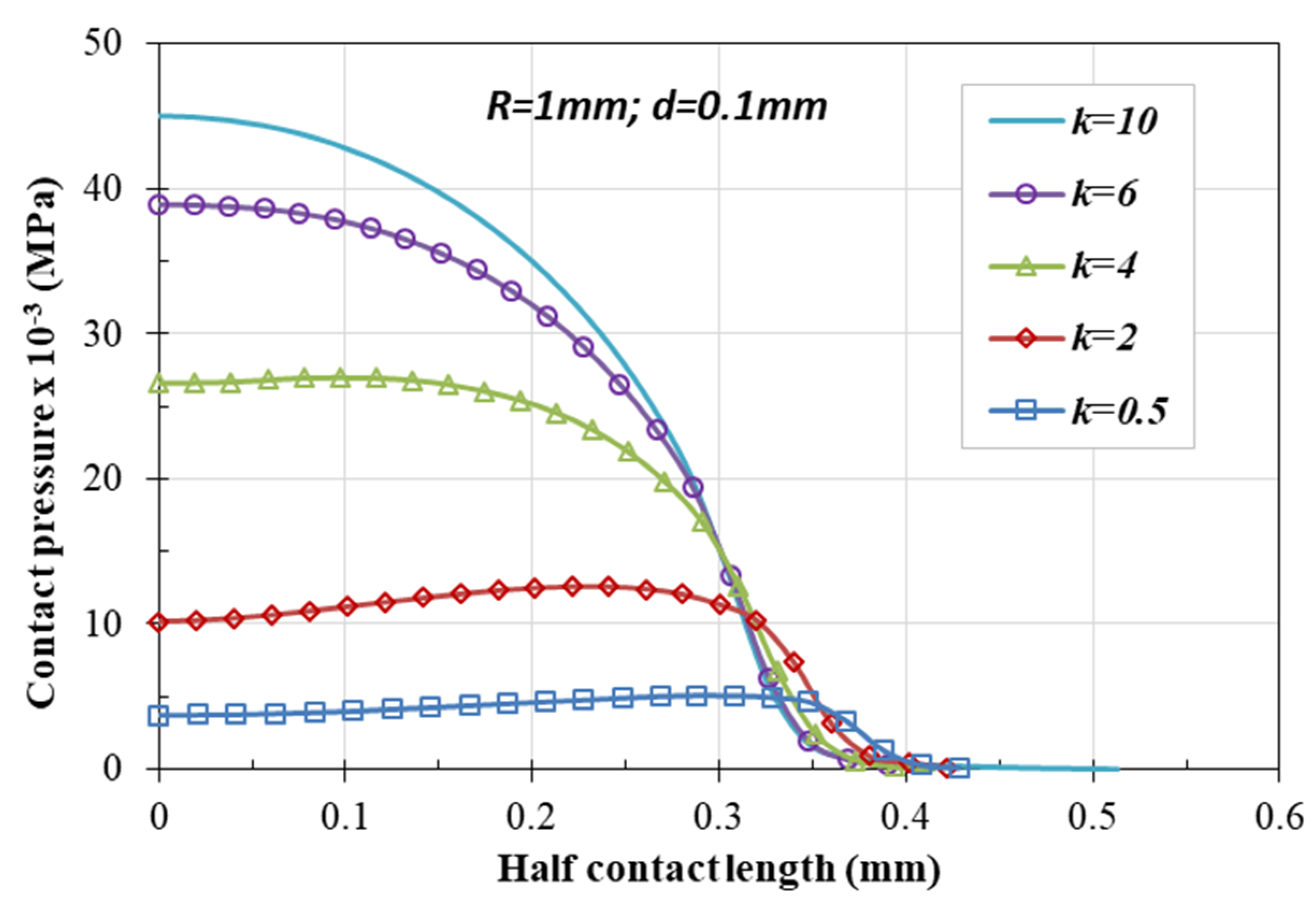
Figure 9 plots the evolution of the contact pressure in the contact interface for different gradient index values. The contact pressure is measured at half load or half contact length, which is equivalent to the indentation depth d = 0.1 mm. As depicted in this figure, the rise of the gradient index leads to an apparent intensification of the contact pressure. Indeed, when gradient index values pass from 0.5 to 4, the maximum of the contact pressure rises by approximately three times.
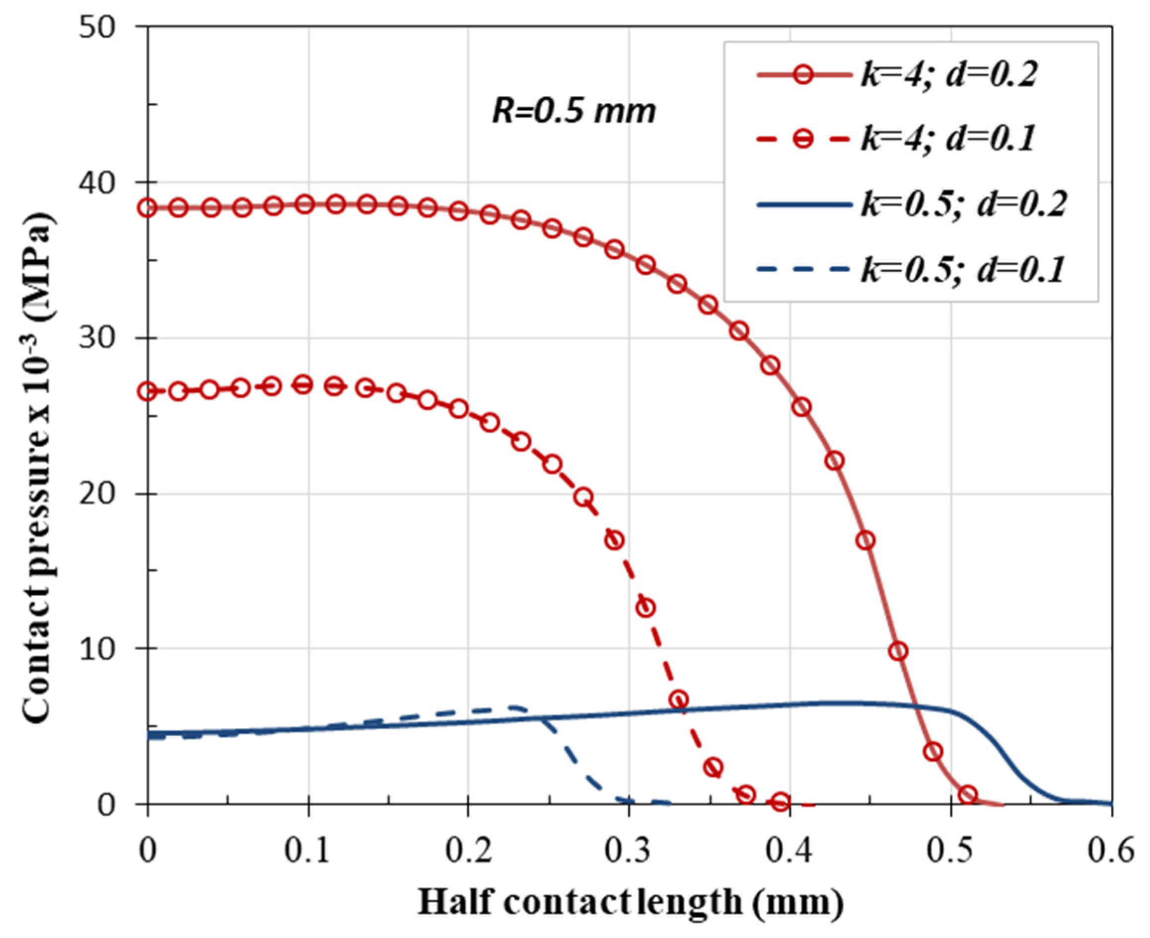
To assess the contact pressure response of the elastoplastic FGM along the loading stages, the contact pressure is measured at both full and half loads, which is equivalent to a vertical displacement of 0.1 mm for a half load and 0.2 mm for a full load. Figure 10 plots the evolution of the contact pressure through the indentation interface at full and half loads corresponding to these two vertical displacement values. For the two cases, the rise of gradient index helps the expansion of the contact pressure with an observable range. Looking to the case of a low power index of 0.5, it is clear that the full and half load response are approximately similar in contrast to the observable difference at high power index values. This is due to the high level of contact force needed to deform the FGM structure with a higher elasticity rate when the ceramic phase portion increases at these values of gradation.
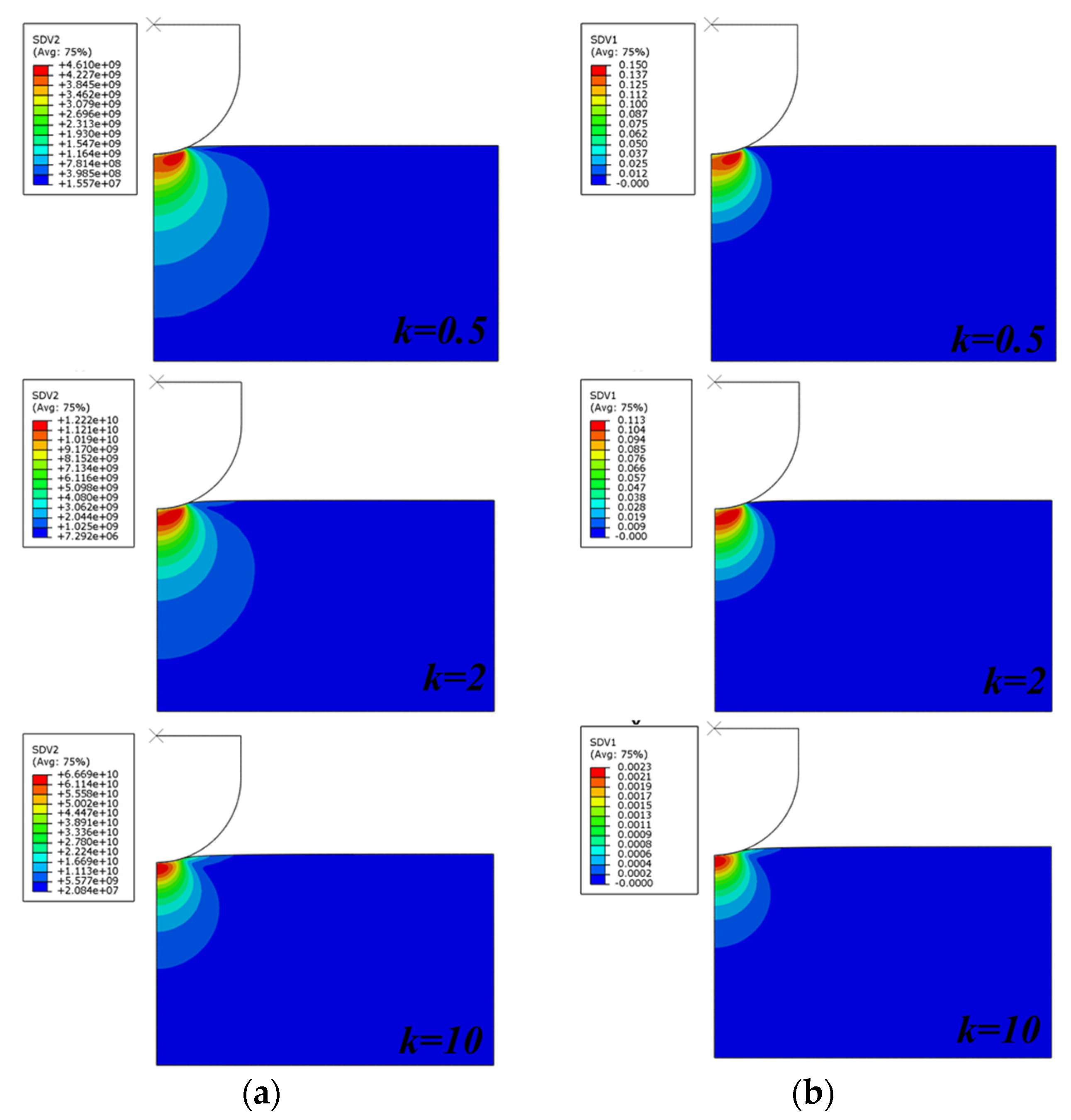
Figure 11 plots the von Mises equivalent stress (Figure 11a) and the equivalent plastic strain (Figure 11b) distributions at variable gradient index values. This figure assesses the effect of this key parameter on the material solicitations during the indentation process of the ceramic/metal FGM plate. The maximum values of stresses and plastic strains are located on the center of the contact zone.
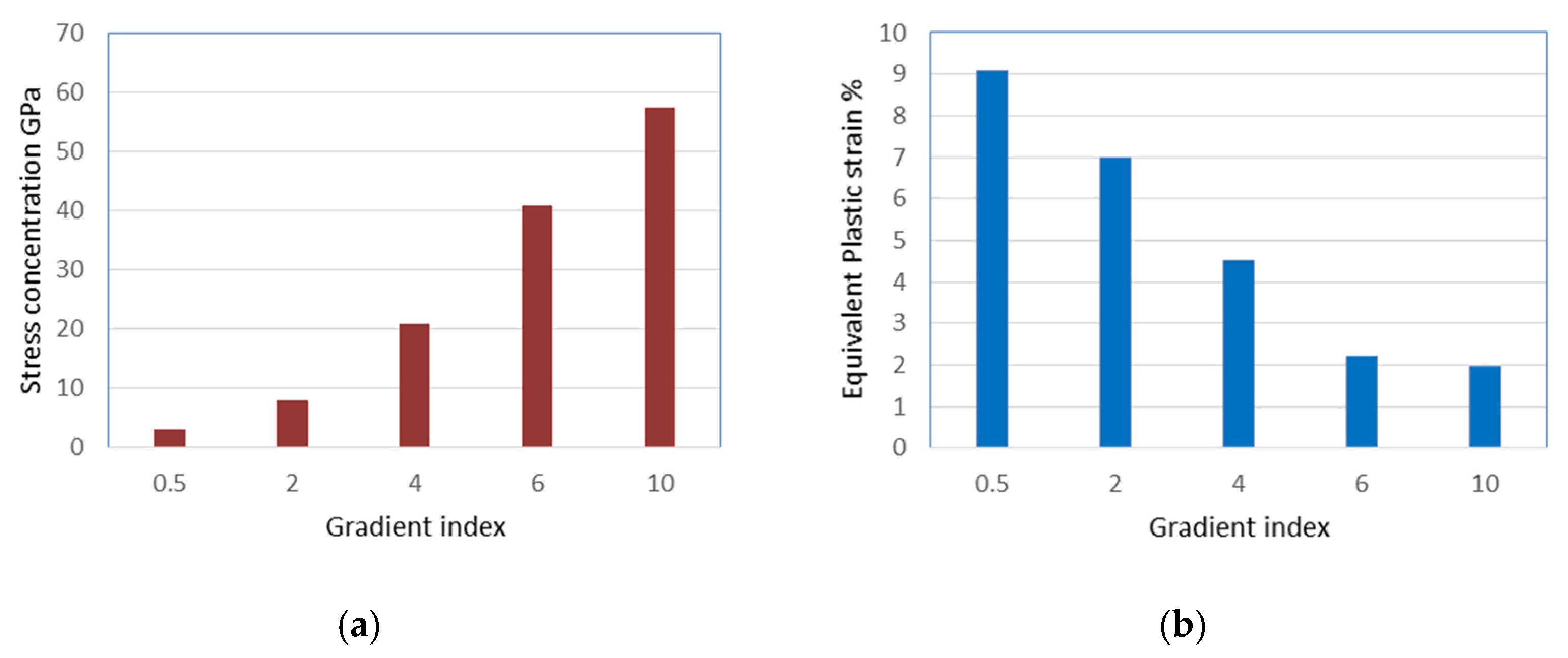
The stress concentration at the center of the contact zone and at the end of the loading phase is illustrated in Figure 12a. The equivalent plastic strain at the center of the contact zone and at the end of the loading phase is presented in Figure 12b. Figure 12 shows that increasing the gradient index leads to an increase in stress at the center of the contact zone and a decrease in the equivalent plastic strain. The maximum von Mises stress is measured for the highest value of the gradient index (k = 10). However, the plastic strains values decreased at this gradient, which is due to the increase in the material elasticity. In fact, the elastoplastic reply of the structure helps plastically deform the sheet at the beginning of loading. The deformation ability of the FGM structure can be initiated by the elastic reaction at the indentation loading; this reaction is trigged by the elastoplastic characteristics of the material. In addition, the increase in the gradient index, as said previously, enhances the stiffness of the FGM structure certainly at the contact zone. In addition, the increase in the ceramic volume fraction has the effect of increasing the surface hardness, which increases the stresses at this zone precisely at the vicinity of the indenter when the composite material starts deformation. Summarizing, any variation in the elastoplastic properties through the thickness of the FGM plate leads to an observable impact on the induced stresses and strains especially if the gradation goes for increasing the volume fraction of the hardest material with higher elasticity levels.
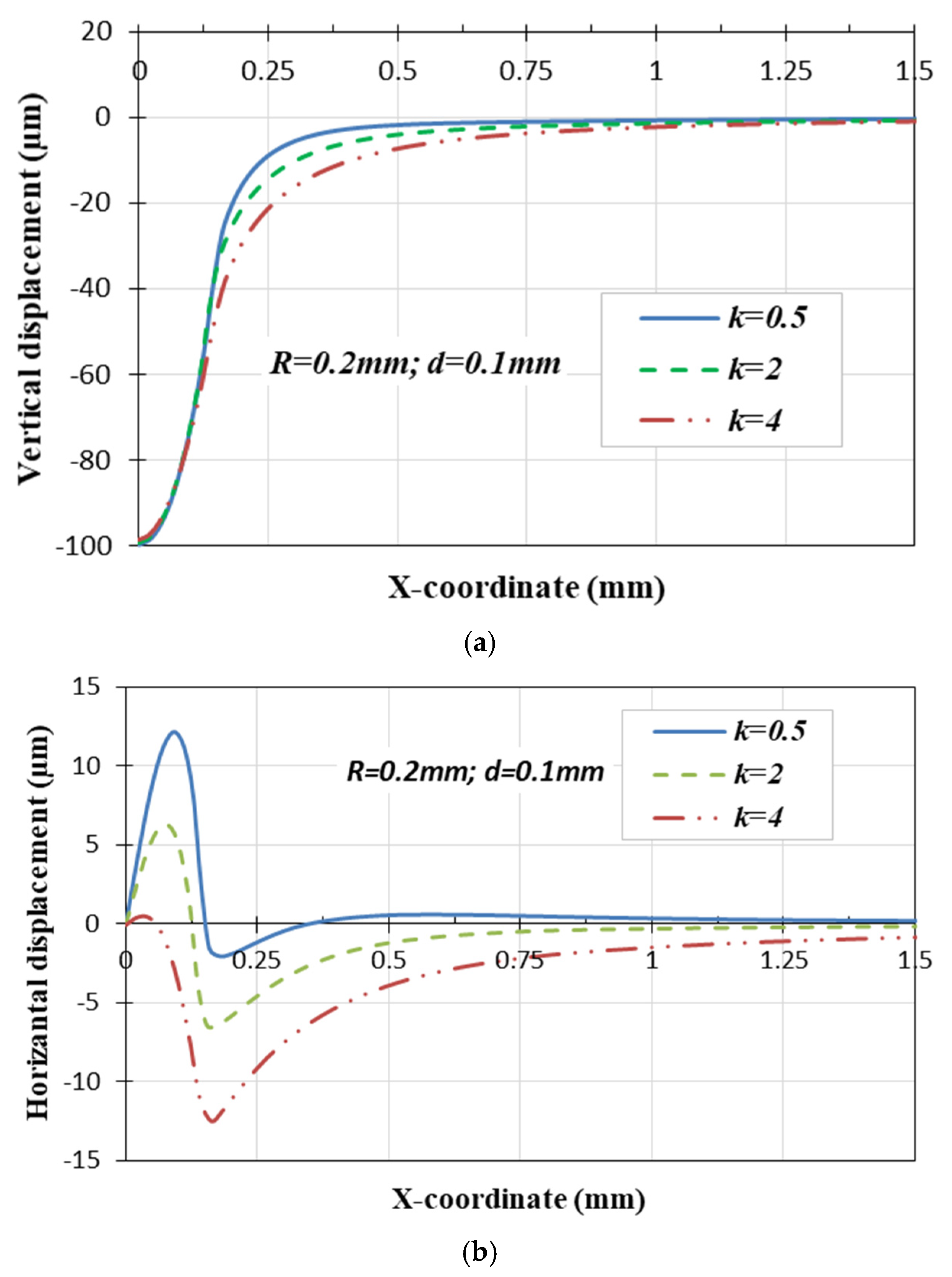
Figure 13 presents shapes of the vertical and horizontal displacements generated at the indented zone at a half load of the indenter under variable gradient index values k = 0.5, 2 and 4. The profile of these displacements is measured on the upper surface of the indented zone of the FGM plate. It is observed that the gradient index has a negligible impact on both the profile and values of the vertical displacement, owing to the nature of the applied load. In contrast, the horizontal displacement exhibits a significant variation with the rise in the gradient index. This variation is attributed to the concentration of stresses under the indenter during loading, as depicted in Figure 12b. Therefore, the surface affected by the horizontal displacement is increased by increasing the gradient index with negative slopes in contrast with the positive slopes in the lower gradient index. Note that the compression stresses created by this type of force around the surface of the contact area during the indentation test can lead to forward wrinkles at the circumferential surface around the indenter.
Figure 14 depicts the impact of the gradient index on the residual vertical and horizontal displacements. The evolution of residual vertical and horizontal displacements plotted in Figure 14 shows that with the increase in the stiffness of the Functionally Graded Material under higher gradient index, the structure dissipates the applied energy, resulting in low permanent deformations. The shapes of residual horizontal and vertical forces have the same trends in the loading stage (Figure 7). However, the difference between the applied displacement and the residual ones were more pronounced at the higher gradient index. This difference can be attributed to the FG structure’s capacity to dissipate deformation energy, which increases with its elasticity, as mentioned earlier. Therefore, it is clear that the phenomenon of springback is more accentuated with a higher gradient index, which explains the residual vertical displacement reductions from k = 0.5 to 4.

4.2. Influence of the Indenter Radius

The impact of the indenter radius on the response of the TiB/Ti FGM is assessed in term of load–indentation depth curve, contact pressure, and vertical and horizontal displacements. Three indenter radii are used: R = 0.2, 0.5 and 1 mm, which are initiated by a vertical displacement d = 0.1 mm and considering two gradient indexes k = 0.5 and 2.
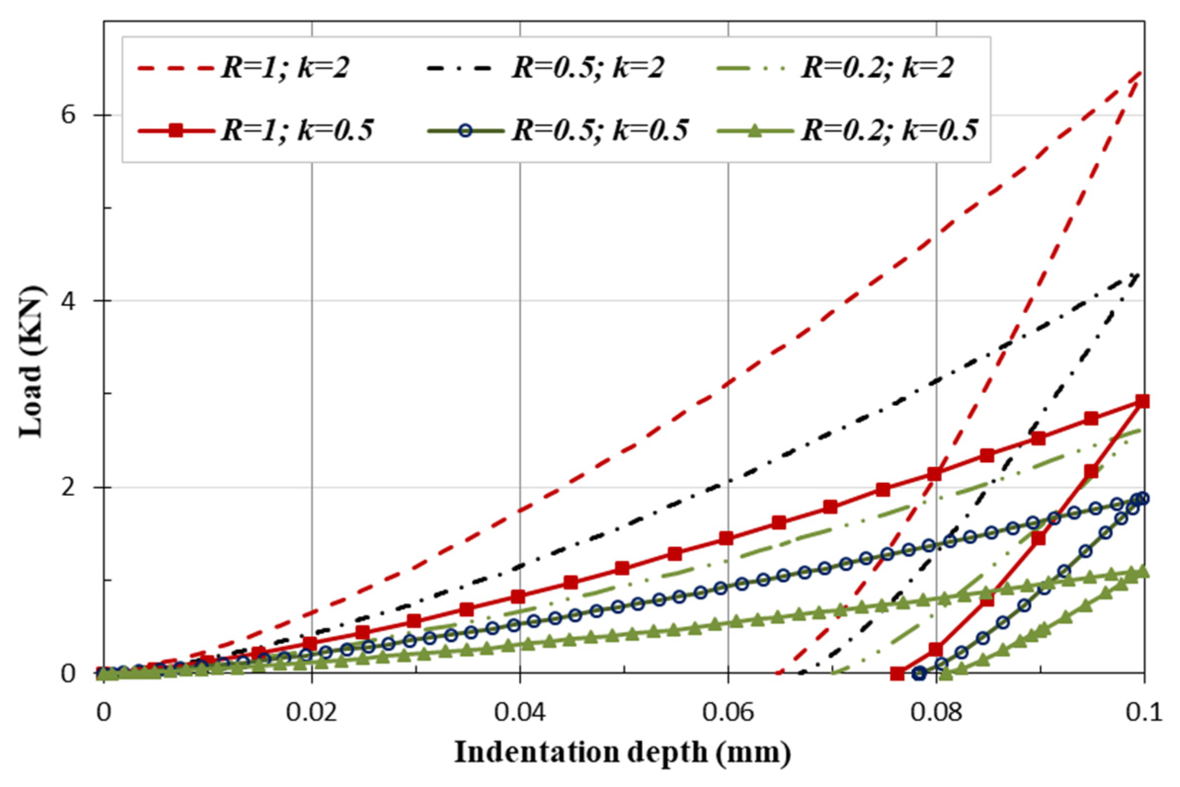
From Figure 15, it can be observed that the increase in load values is influenced by the augmentation of the indenter radius. In fact, by increasing the tool radius, the surface of contact also increases, pushing up the indentation load. This increasing effect will be amplified by the increase in the FGM stiffness when the gradient index increases, which means that the resistance of the composite material to deformation will increase. Note that the influence of the indenter radius is more observable in contrast with the gradient index. The shape and trend of the load/indentation depth curves is similar with different indenter radii.
The profile of the contact pressure measured on the contact zone between the spherical indenter with variable diameter (0.2, 0.5 and 1 mm) and the FG plate is plotted on Figure 16. Here, it is observable that the rise of the indenter radius distributes the contact pressure over a larger surface, which decreases its value. Hence, smaller indenters will cause more pressure in a smaller contact area, which is a stress concentration in a smaller zone located on the vicinity of the tool head.
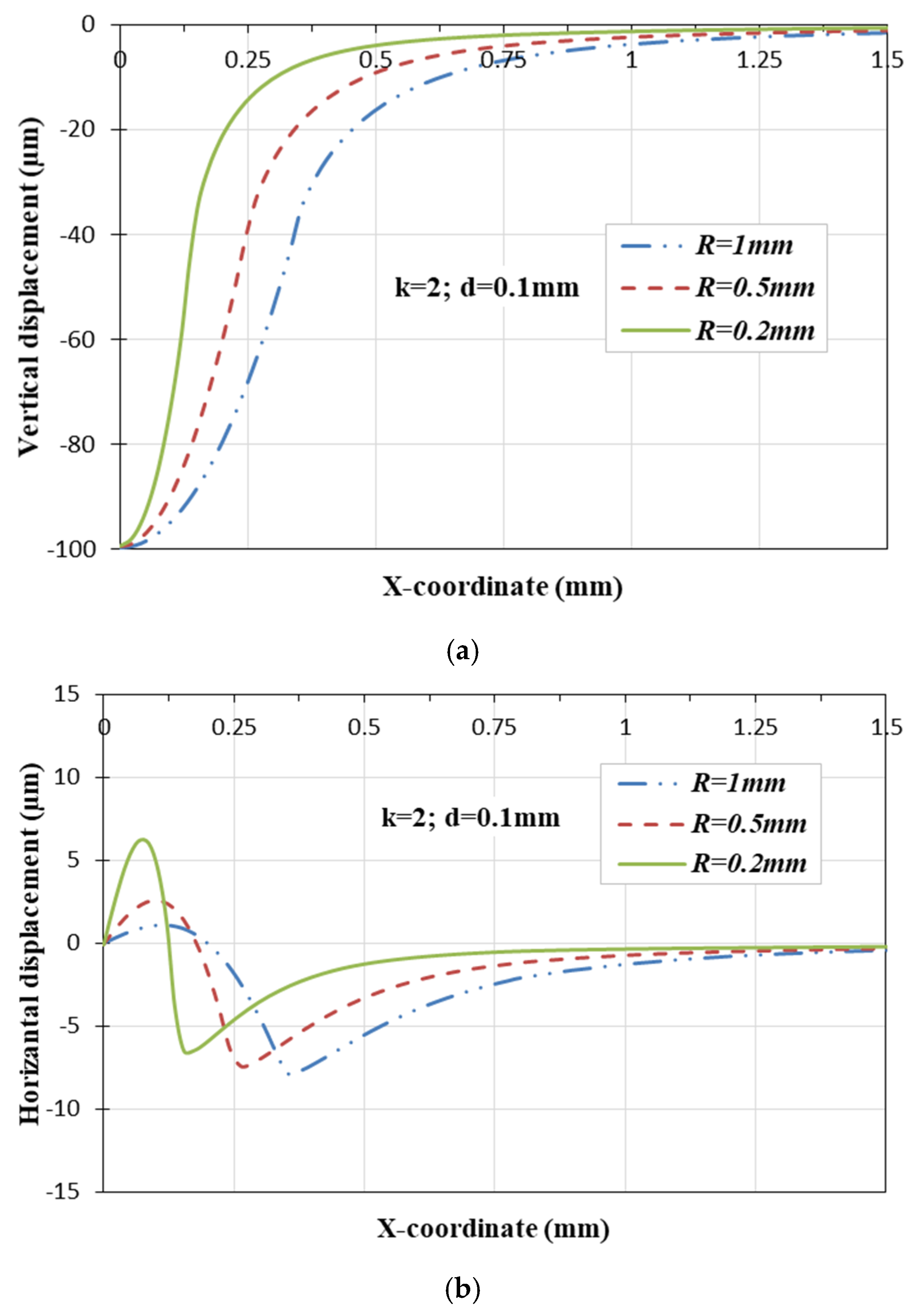
Figure 17 plots the effect of the variation of the indenter radius on the evolution of the horizontal and vertical displacements with a gradient index of k = 2 and pre-described vertical displacement of d = 0.1 mm. Indeed, there is no notable difference in the behavioral response of the FG plate in terms of vertical displacements when the indenter radius varies. There is merely an increase in the indented surface, as illustrated in Figure 17a. Figure 17b demonstrates that the increase in indenter radius results in a reduction in residual horizontal displacement.
Figure 18 depicts the residual vertical and horizontal displacements for various indenter radii. From Figure 18a, one can observe that after unloading, the springback phenomenon is more prominent for the higher indenter radius. This is coupled by a reduction in residual horizontal displacement, as depicted in Figure 18b. That means the surface of the TiB/Ti FGM plate will undergo fewer deformations with larger indenters.
Comparing the profiles of horizontal displacements plotted in Figure 13 and Figure 14 with those plotted in Figure 17 and Figure 18, it can be concluded that changing the spherical indenter radius has almost no significance on the qualitative displacement shapes response of the FG structure. However, the influence of the gradient index is most noticeable. This emphasizes the significant role of the elastic parameters of the FG plate in affecting the residual effects after an indentation test, such as hardness tests.

5. Conclusions

The present paper has developed a numerical investigation analyzing the mechanical behavior described with an elastoplastic 2D axisymmetric contact model. The properties of this contact model have been implemented into ABAQUS by a UMAT subroutine based on a mathematical model detailed on the text. This model has described the gradation through the thickness of the elastoplastic properties using a power-law function with a Mori–Tanaka model and self-consistent formulas of Suquet. The aim of the different simulations prepared using this model is to assess the response of a ceramic/metallic FG structure to a spherical indentation. The efficiency of the developed model has been highlighted through a comparison with experimental results from the literature. From the parametric analysis presented in this work, it is concluded that the increase in the gradient index is the key parameter influencing the behavior of the TiB/Ti FG structure. In fact, by increasing the ceramic volume fraction, the FG plate becomes more resistant to indentation, as indicated by the rise in its stiffness and surface hardness. The ability of a high elastic FG structure to overcome the indentation is highlighted by an observable springback that happens after indentation unloading. This behavior can be widely beneficial in several industrial applications such as the coating of aerospace and aircraft components, for sport cars, medical implants, etc. The results presented in the present paper could be helpful to guide developers to study the damage of indented structures or those that have undergone a crash test. Indeed, using FG surfaces with a suitable gradation of elastic parameters could restrain contact damage in tribological applications.

Author Contributions

A.K.: Conceptualization, Methodology, Writing—Original draft preparation, M.A. (Marwa Allouch): Methodology, Writing—Original draft preparation, Software. H.J.: Software, Visualization, Investigation. J.M.: Conceptualization, Methodology, Writing—Original draft preparation, L.B.S.: Conceptualization, Methodology, Writing—Original draft preparation. M.A. (Muapper Alhadri): Software, Visualization, Data curation, Investigation. M.W.: Visualization, Writing—Review and editing, Investigation. F.D.: Supervision, Conceptualization, Methodology, Writing—Review and editing. All authors have read and agreed to the published version of the manuscript.

Funding

This research has been funded by the Scientific Research Deanship at University of Ha’il—Saudi Arabia through project number RG-23 095.

Institutional Review Board Statement

Not applicable.

Informed Consent Statement

Not applicable.

Data Availability Statement

Data are contained within the article.

Conflicts of Interest

The authors declare no conflicts of interest.

References

  1. Ziadoon Mohammed Rahi, A.H.; Al-Khazraji, A.N.; Shandookh, A.A. Mechanical properties investigation of composite FGM fabricated from Al/Zn. Open Eng. 2022, 12, 789–798. [Google Scholar] [CrossRef]
  2. Shareef, M.M.; Al-Khazraji, A.N.; Amin, S.A. Flexural properties of functionally graded silica nanoparticles. In IOP Conference Series: Materials Science and Engineering; IOP Publishing: Bristol, UK, 2021; Volume 1094, p. 012174. [Google Scholar]
  3. Chung, Y.L.; Gan, Y.P. Carry-over Factors of Levy-type rectangular FGM plates subjected to edge moment or deflection. Mech. Mater. 2022, 173, 104413. [Google Scholar] [CrossRef]
  4. Sarkar, L.; Saha, S.; Samanta, R.; Sinha, A.; Mandal, G.; Biswas, A.; Das, A. Recent Progress in CNT-Reinforced Composite and FGM for Multi-functional Space Applications and Future Directions. J. Inst. Eng. India Ser. D 2023. [Google Scholar] [CrossRef]
  5. Kumar, P.; Sharma, S.K.; Singh, R.K.R. Recent trends and future outlooks in manufacturing methods and applications of FGM: A comprehensive review. Mater. Manuf. Process. 2023, 38, 1033–1067. [Google Scholar] [CrossRef]
  6. Elishakoff, I.; Chotpatthamanon, C.; Reddy, J.N. Buckling of a column made of the functionally graded material with high-order polynomial mode shape. Math. Mech. Solids 2023, 28, 1745–1759. [Google Scholar] [CrossRef]
  7. Kumar, P.; Harsha, S.P. Response analysis of hybrid functionally graded material plate subjected to thermo-electro-mechanical loading. Proc. Inst. Mech. Eng. Part L J. Mater. Des. Appl. 2020, 235, 813–827. [Google Scholar] [CrossRef]
  8. Jrad, H.; Mallek, H.; Wali, M.; Dammak, F. Finite element formulation for active functionally graded thin-walled structures. C. R. Méc. 2018, 346, 1159–1178. [Google Scholar] [CrossRef]
  9. Mallek, H.; Jrad, H.; Wali, M.; Dammak, F. Piezoelastic response of smart functionally graded structure with integrated piezoelectric layers using discrete double directors shell element. Compos. Struct. 2019, 210, 354–366. [Google Scholar] [CrossRef]
  10. Wang, S.; Kang, W.; Yang, W.; Zhang, Z.; Li, Q.; Liu, M.; Wang, X. Hygrothermal effects on buckling behaviors of porous bi-directional functionally graded micro-/nanobeams using two-phase local/nonlocal strain gradient theory. Eur. J. Mech.-A/Solids 2022, 94, 104554. [Google Scholar] [CrossRef]
  11. Van Vinh, P.; Van Chinh, N.; Tounsi, A. Static bending and buckling analysis of bi-directional functionally graded porous plates using an improved first-order shear deformation theory and FEM. Eur. J. Mech.-A/Solids 2022, 96, 104743. [Google Scholar] [CrossRef]
  12. Zhou, W.; Ai, S.; Chen, M.; Zhang, R.; He, R.; Pei, Y.; Fang, D. Preparation and thermodynamic analysis of the porous ZrO2/(ZrO2+Ni) functionally graded bolted joint. Compos. Part B Eng. 2015, 82, 13–22. [Google Scholar] [CrossRef]
  13. Zhou, W.; Zhou, H.; Zhang, R.; Pei, Y.; Fang, D. Measuring residual stress and its influence on properties of porous ZrO2/(ZrO2+Ni) ceramics. Mater. Sci. Eng. A 2015, 622, 82–90. [Google Scholar] [CrossRef]
  14. Jana, T.; Mitra, A.; Sahoo, P. Contact behavior of functionally graded fractal surface. Proc. Inst. Mech. Eng. Part L J. Mater. Des. Appl. 2020, 234, 1355–1374. [Google Scholar] [CrossRef]
  15. Jitcharoen, J.; Padture, N.P.; Giannakopoulos, A.E.; Suresh, S. Hertzian-crack suppression in ceramics with elastic-modulus-graded surfaces. J. Am. Ceram. Soc. 1998, 81, 2301–2308. [Google Scholar] [CrossRef]
  16. Zhang, Y.; Cheng, Z.; Feng, H. Dynamic Fracture Analysis of Functional Gradient Material Coating Based on the Peridynamic Method. Coatings 2019, 9, 62. [Google Scholar] [CrossRef]
  17. Mellouli, H.; Jrad, H.; Wali, M.; Dammak, F. Free vibration analysis of FG-CNTRC shell structures using the meshfree radial point interpolation method. Comput. Math. Appl. 2020, 79, 3160–3178. [Google Scholar] [CrossRef]
  18. Mallek, H.; Jrad, H.; Wali, M.; Kessentini, A.; Gamaoun, F.; Dammak, F. Dynamic analysis of functionally graded carbon nanotube–reinforced shell structures with piezoelectric layers under dynamic loads. J. Vib. Control 2019, 26, 1157–1172. [Google Scholar] [CrossRef]
  19. Marinković, D.; Köppe, H.; Gabbert, U. Aspects of modeling piezoelectric active thin-walled structures. J. Intell. Mater. Syst. Struct. 2009, 20, 1835–1844. [Google Scholar] [CrossRef]
  20. Marinković, D.; Rama, G.; Zehn, M. Abaqus implementation of a corotational piezoelectric 3-node shell element with drilling degree of freedom. Facta Univ. Ser. Mech. Eng. 2019, 17, 269–283. [Google Scholar] [CrossRef]
  21. Majumdar, A.; Das, D. A study on thermal buckling load of clamped functionally graded beams under linear and nonlinear thermal gradient across thickness. Proc. Inst. Mech. Eng. Part L J. Mater. Des. Appl. 2018, 232, 769–784. [Google Scholar] [CrossRef]
  22. Rahmani, M.; Mohammadi, Y.; Kakavand, F. Buckling analysis of different types of porous FG conical sandwich shells in various thermal surroundings. J. Braz. Soc. Mech. Sci. Eng. 2020, 42, 164. [Google Scholar] [CrossRef]
  23. Gunes, R.; Aydin, M. Elastic response of functionally graded circular plates under a drop-weight. Compos. Struct. 2010, 92, 2445–2456. [Google Scholar] [CrossRef]
  24. Najafi, F.; Shojaeefard, M.H.; Googarchin, H.S. Nonlinear low-velocity impact response of functionally graded plate with nonlinear three-parameter elastic foundation in thermal field. Compos. Part B Eng. 2016, 107, 123–140. [Google Scholar] [CrossRef]
  25. Wagih, A.; Attia, M.A.; Abdel Rahman, A.A.; Bendine, K.; Sebaey, T.A. On the indentation of elastoplastic functionally graded materials. Mech. Mater. 2019, 129, 169–188. [Google Scholar] [CrossRef]
  26. Alijani, A.; Darvizeh, M.; Darvizeh, A.; Ansari, R. Elasto-plastic pre-and post-buckling analysis of functionally graded beams under mechanical loading. Proc. Inst. Mech. Eng. Part L J. Mater. Des. Appl. 2015, 229, 146–165. [Google Scholar] [CrossRef]
  27. Gunes, R.; Aydin, M.; Apalak, M.K.; Reddy, J.N. Experimental and numerical investigations of low velocity impact on functionally graded circular plates. Compos. Part B Eng. 2014, 59, 21–32. [Google Scholar] [CrossRef]
  28. Tamura, I. Strength and ductility of Fe-Ni-C alloys composed of austenite and martensite with various strength. In Proceedings of the Third International Conference on Strength of Metals and Alloys, Cambridge, UK, 20–25 August 1973; Institute of Metals: Cambridge, UK, 1973; Volume 1, pp. 611–615. [Google Scholar]
  29. Zhang, J.; Qi, D.; Zhou, L.; Zhao, L.; Hu, N. A progressive failure analysis model for composite structures in hygrothermal environments. Compos. Struct. 2015, 133, 331–342. [Google Scholar] [CrossRef]
  30. Kalali, A.T.; Hadidi-Moud, S. A semi-analytical approach to elastic-plastic stress analysis of FGM pressure vessels. J. Solid Mech. 2013, 5, 63–73. [Google Scholar]
  31. Xu, G.; Huang, H.; Chen, B.; Chen, F. Buckling and postbuckling of elastoplastic FGM plates under inplane loads. Compos. Struct. 2017, 176, 225–233. [Google Scholar] [CrossRef]
  32. Bocciarelli, M.; Bolzon, G.; Maier, G. A constitutive model of metal–ceramic functionally graded material behavior: Formulation and parameter identification. Comput. Mater. Sci. 2008, 43, 16–26. [Google Scholar] [CrossRef]
  33. Azoti, W.L.; Tchalla, A.; Koutsawa, Y.; Makradi, A.; Rauchs, G.; Belouettar, S.; Zahrouni, H. Mean-field constitutive modeling of elasto-plastic composites using two (2) incremental formulations. Compos. Struct. 2013, 105, 256–262. [Google Scholar] [CrossRef]
  34. Castaneda, P.P. Second-order homogenization estimates for nonlinear composites incorporating field fluctuations: I-theory. J. Mech. Phys. Solid 2002, 50, 737–757. [Google Scholar] [CrossRef]
  35. Atrian, A.; Majzoobi, G.H.; Nourbakhsh, S.H.; Galehdari, S.A.; Nejad, R.M. Evaluation of tensile strength of Al7075-SiC nanocomposite compacted by gas gun using spherical indentation test and neural networks. Adv. Powder Technol. 2016, 27, 1821–1827. [Google Scholar] [CrossRef]
  36. Orlik, J. Asymptotic homogenization algorithm for reinforced metal-matrix elasto-plastic composites. Compos. Struct. 2010, 92, 1581–1590. [Google Scholar] [CrossRef]
  37. Suquet, P. Effective properties of nonlinear composites. In Continuum Micromechanics; Springer: Vienna, Austria, 1997; pp. 197–264. [Google Scholar]
  38. Suquet, P.M. Elements of Homogenization for Inelastic Solid Mechanics. In Mechanics of Materials with Internal Structure; Cracow University of Technology: Cracow, Poland, 1985; pp. 197–221. [Google Scholar]
  39. Ponte Castañeda, P. New Variational Principles in Plasticity and Their Application to Composite Materials. J. Mech. Phys. Solids 1991, 39, 1573–1600. [Google Scholar] [CrossRef]
  40. Mao, Y.; Fu, Y.; Fang, D. Interfacial damage analysis of shallow spherical shell with FGM coating under low velocity impact. Int. J. Mech. Sci. 2013, 71, 30–40. [Google Scholar] [CrossRef]
  41. Etemadi, E.; Khatibi, A.A.; Takaffoli, M. 3D finite element simulation of sandwich panels with a functionally graded core subjected to low velocity impact. Compos. Struct. 2015, 89, 28–34. [Google Scholar] [CrossRef]
  42. Jrad, H.; Mars, J.; Wali, M.; Dammak, F. Geometrically nonlinear analysis of elastoplastic behavior of functionally graded shells. Eng. Comput. 2019, 35, 833–847. [Google Scholar] [CrossRef]
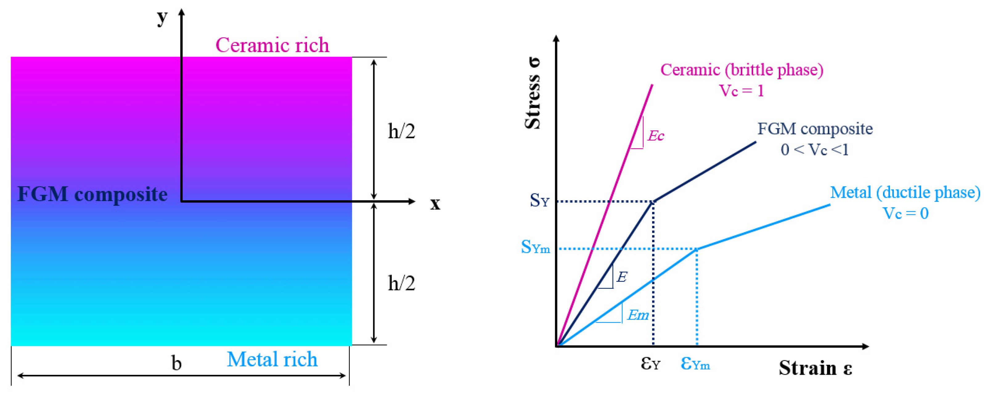
Figure 1. Typical stress/stain curve for elastoplastic FGM based on Mori–Tanaka model and self-consistent formulas of Suquet.
Mathematics 12 00209 g001
Figure 2. FE model used to simulate the indentation of the FG plate.
Mathematics 12 00209 g002
Figure 3. Flowchart illustrating material implementation methodology using the UMAT subroutine.
Mathematics 12 00209 g003
Figure 4. Numerical indentation load–depth versus experimental load–depth curve [35].
Mathematics 12 00209 g004
Figure 5. Load to indentation depth considering the variable gradient index (indenter radius R = 0.2 mm, d = 0.1 mm).
Mathematics 12 00209 g005
Figure 6. Load to indentation depth considering the variable gradient index (indenter radius R = 0.5 mm, d = 0.1 mm).
Mathematics 12 00209 g006
Figure 7. Load to indentation depth considering the variable gradient index (indenter radius R = 1 mm, d = 0.1 mm).
Mathematics 12 00209 g007
Figure 8. Load versus indentation depth considering the variable gradient index (indenter radius R = 1 mm, d = 0.2 mm). (a) k = 0.5, 2, 4, 6 and 10; (b) k = 0, 0.25, 0.5 and 1.
Mathematics 12 00209 g008
Figure 9. The contact pressure evolution at half load considering variable gradient index values (indenter radius R = 1 mm and d = 0.1 mm).
Mathematics 12 00209 g009
Figure 10. The contact pressure evolution at half load considering indenter radius R = 0.5 mm, k = 0.5; 4 and d = 0.1; 0.2.
Mathematics 12 00209 g010
Figure 11. (a) Von Mises stress distribution, (b) equivalent plastic strain considering variable gradient index values for R = 1 mm and d = 0.1 mm.
Mathematics 12 00209 g011
Figure 12. (a) Stress concentration, (b) equivalent plastic strain considering variable gradient index values for R = 1 mm and d = 0.1 mm.
Mathematics 12 00209 g012
Figure 13. (a) Vertical displacement, (b) horizontal displacement under variable gradient index values considering R = 0.2 mm and d = 0.1 mm.
Mathematics 12 00209 g013
Figure 14. (a) Residual vertical displacement, (b) Residual horizontal displacement under variable gradient index values considering R = 0.2 mm and d = 0.1 mm.
Mathematics 12 00209 g014
Figure 15. Load–depth curve under variable indenter radius with k = 0.5, 2 and d = 0.1 mm.
Mathematics 12 00209 g015
Figure 16. Contact pressure distribution under variable indenter radius with k = 2 and d = 0.1 mm.
Mathematics 12 00209 g016
Figure 17. Displacement evolutions under different indenter radius: (a) vertical displacement, (b) horizontal displacement considering k = 2 and d = 0.1 mm.
Mathematics 12 00209 g017
Figure 18. Displacement evolutions under different indenter radius: (a) residual vertical displacement, (b) residual horizontal displacement considering k = 2 and d = 0.1 mm.
Mathematics 12 00209 g018
Table 1. Elastoplastic material properties of TiB/Ti material.
Ec (GPa)νcEm (GPa)νmσym (MPa)Km (GPa)nm
3750.141070.34450141
Table 2. Maximum of indentation load in kN for different indenter radius and gradient index.
Indenter Radius R (mm)Displacement d (mm)Gradient Index k
0.524610
10.12.56121618
0.2717355057
0.5 0.124.58.51113
0.20.112.557.59
Disclaimer/Publisher’s Note: The statements, opinions and data contained in all publications are solely those of the individual author(s) and contributor(s) and not of MDPI and/or the editor(s). MDPI and/or the editor(s) disclaim responsibility for any injury to people or property resulting from any ideas, methods, instructions or products referred to in the content.