
Efficient 5.8 GHz Microstrip Antennas for Intelligent Transportation Systems: Design, Fabrication, and Performance Analysis

 , ,
, ,  and
and
Abstract
:1. Introduction
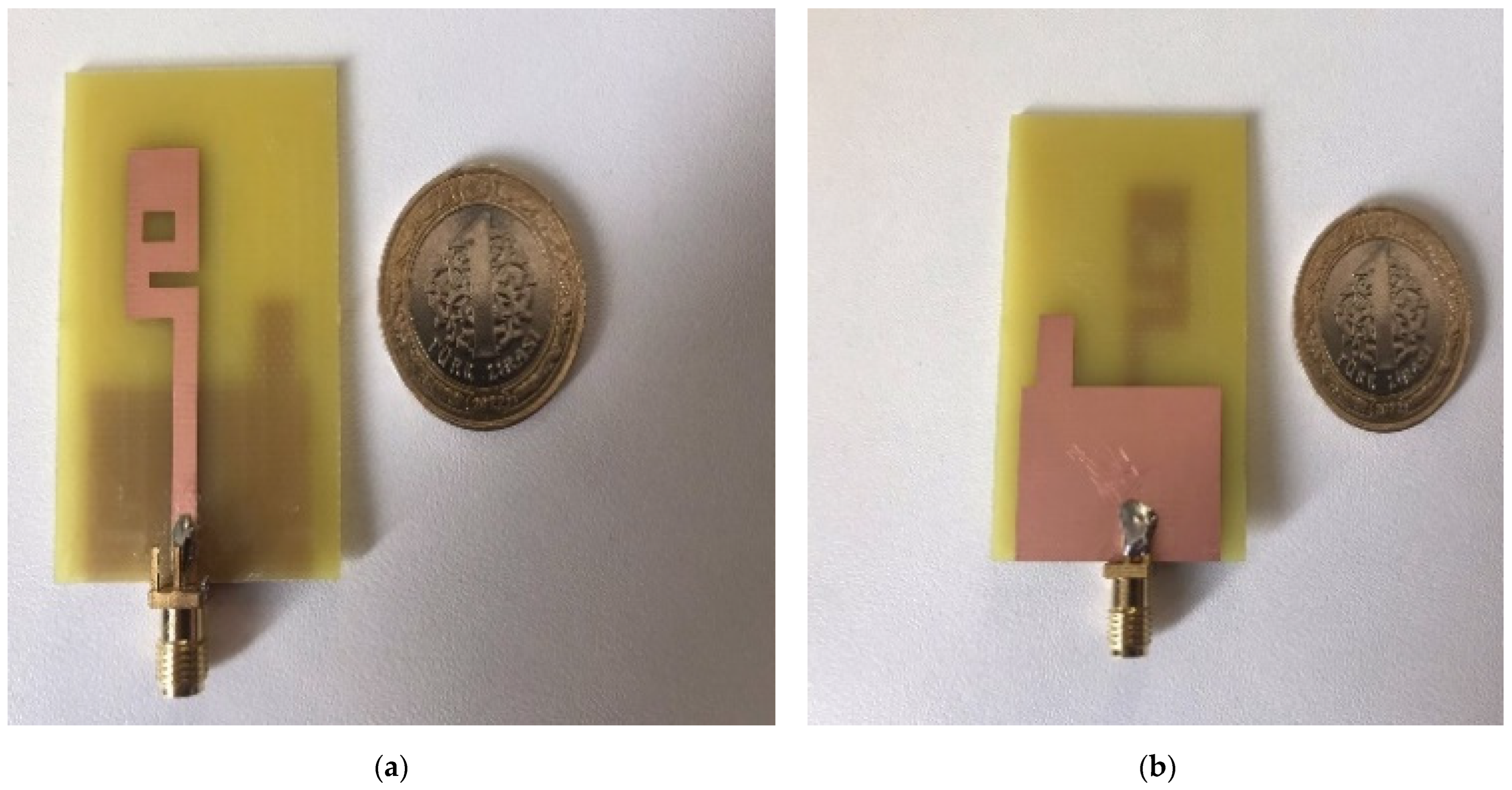
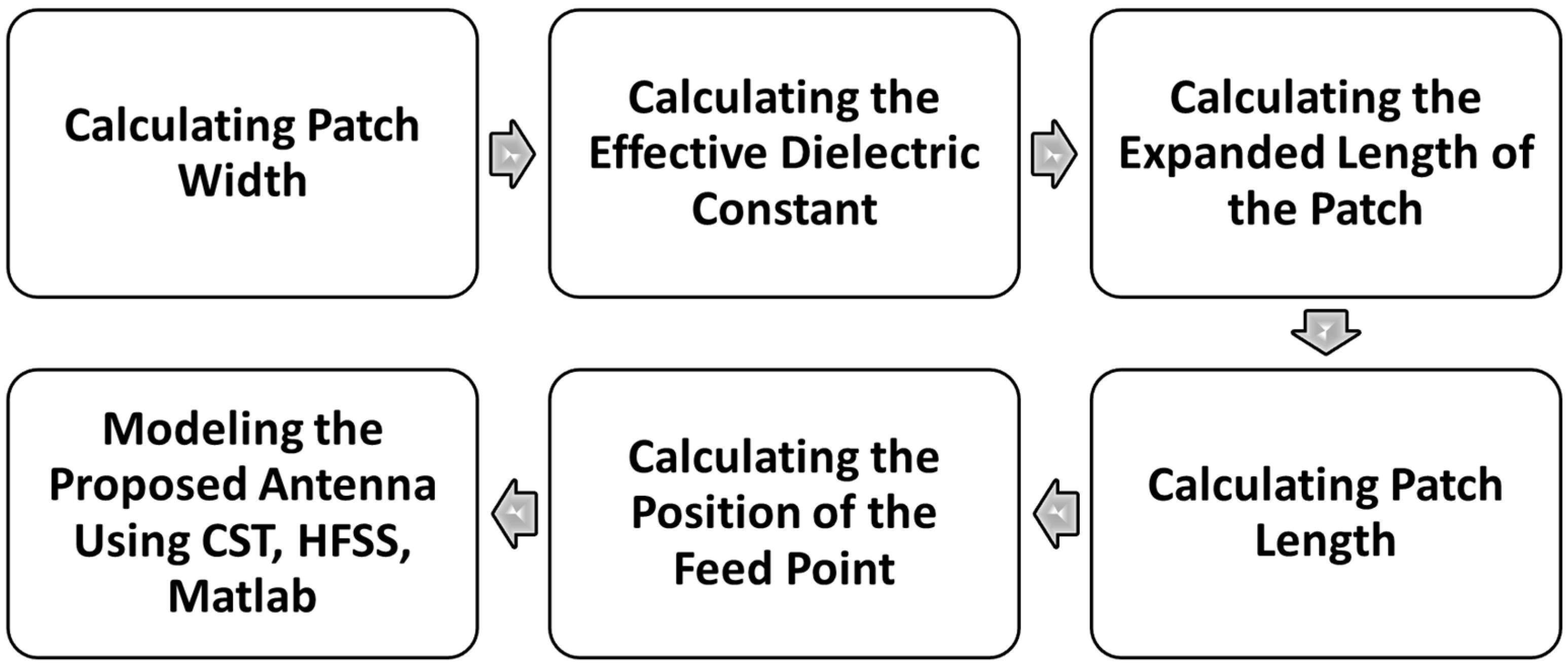
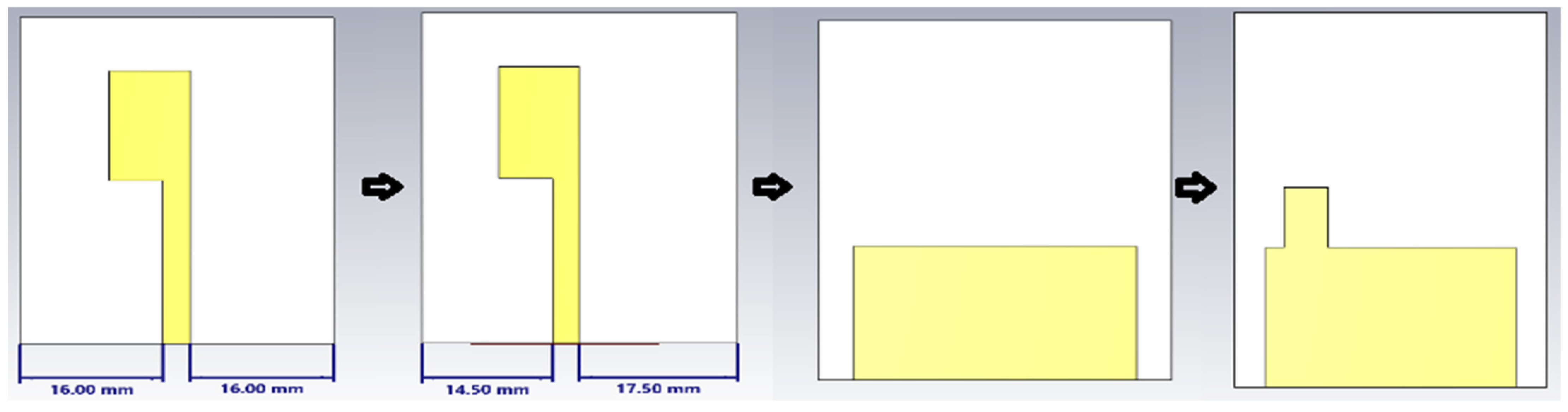
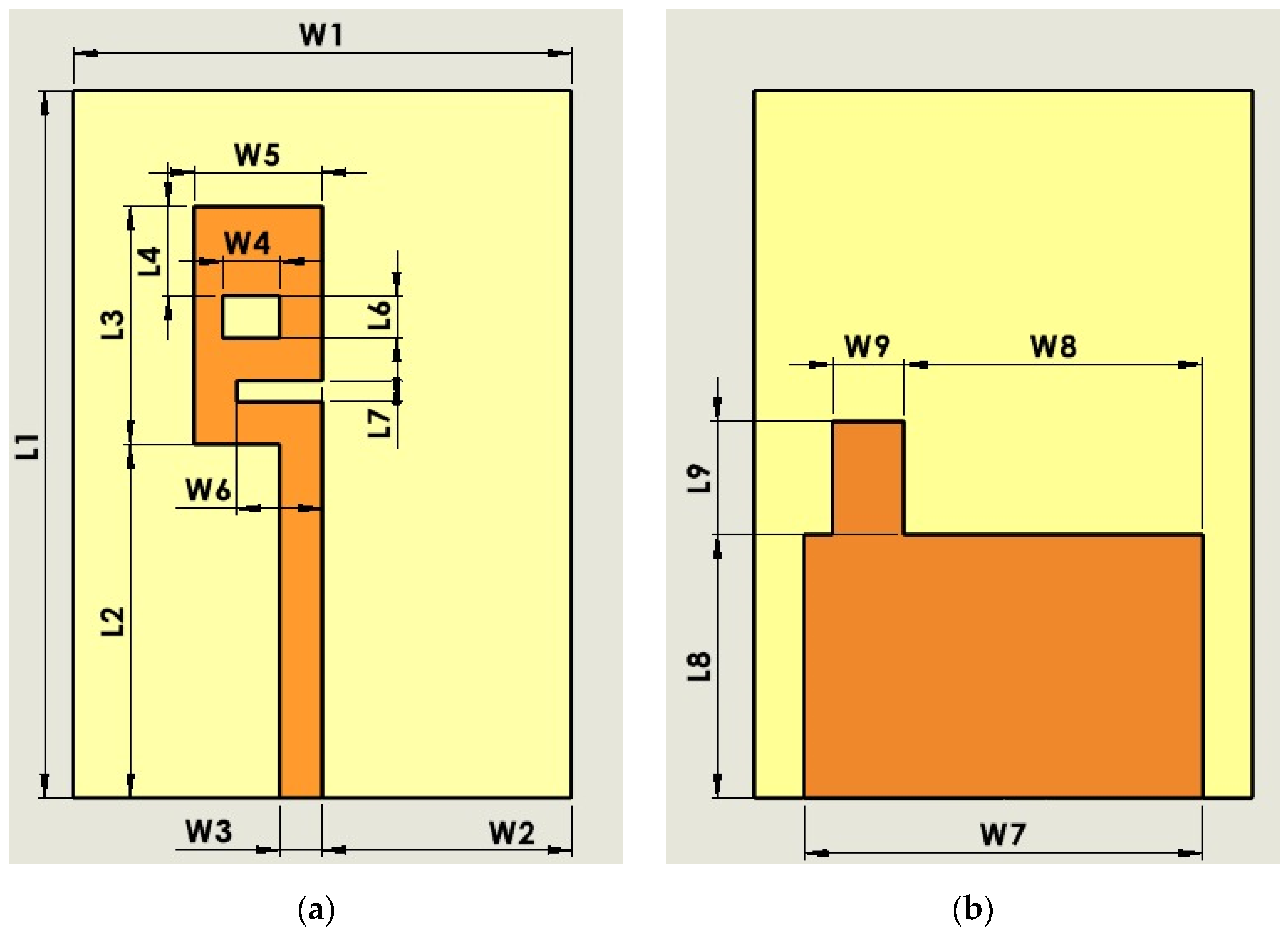
2. Antenna Design
3. Research Findings and Discussion
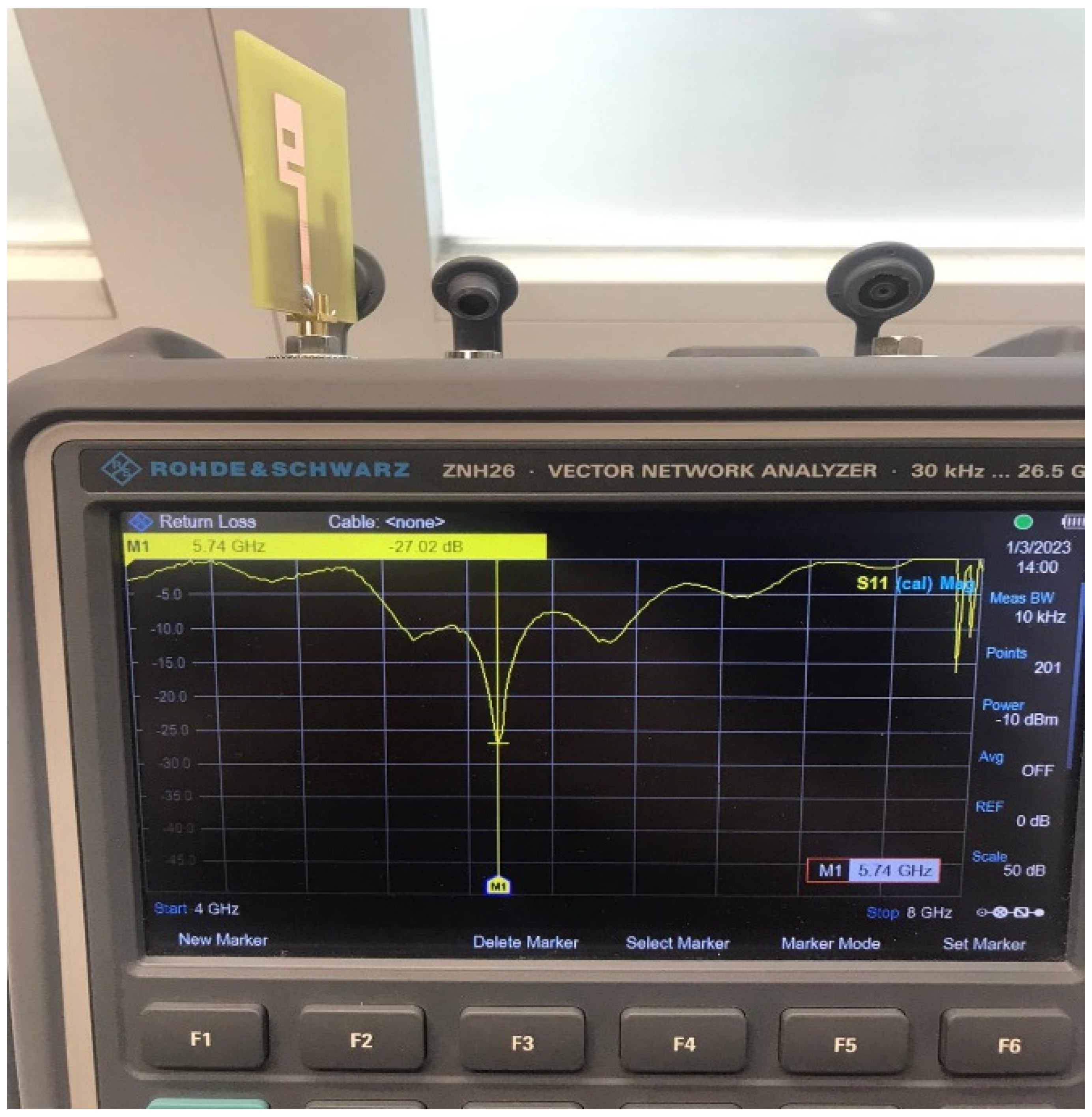
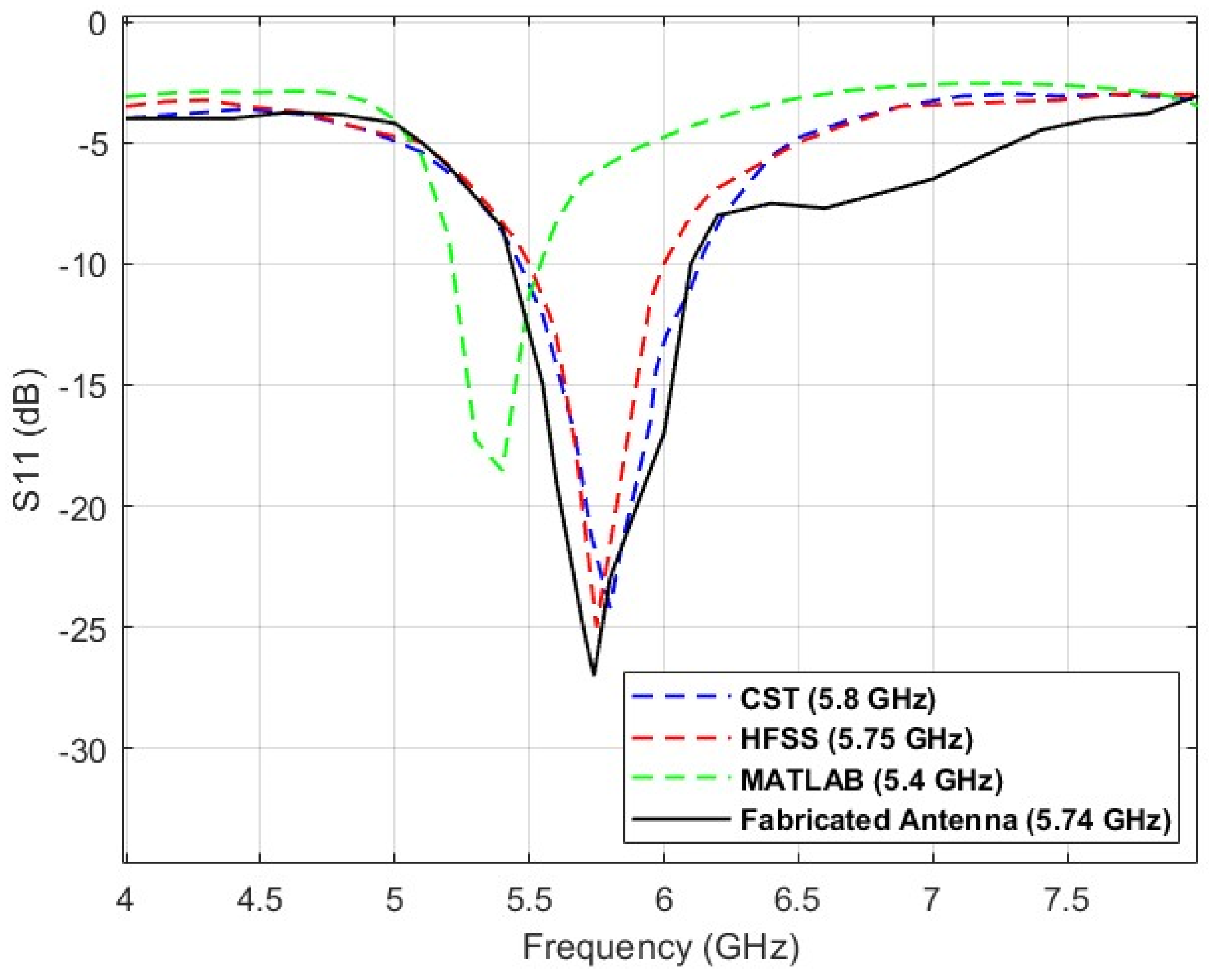
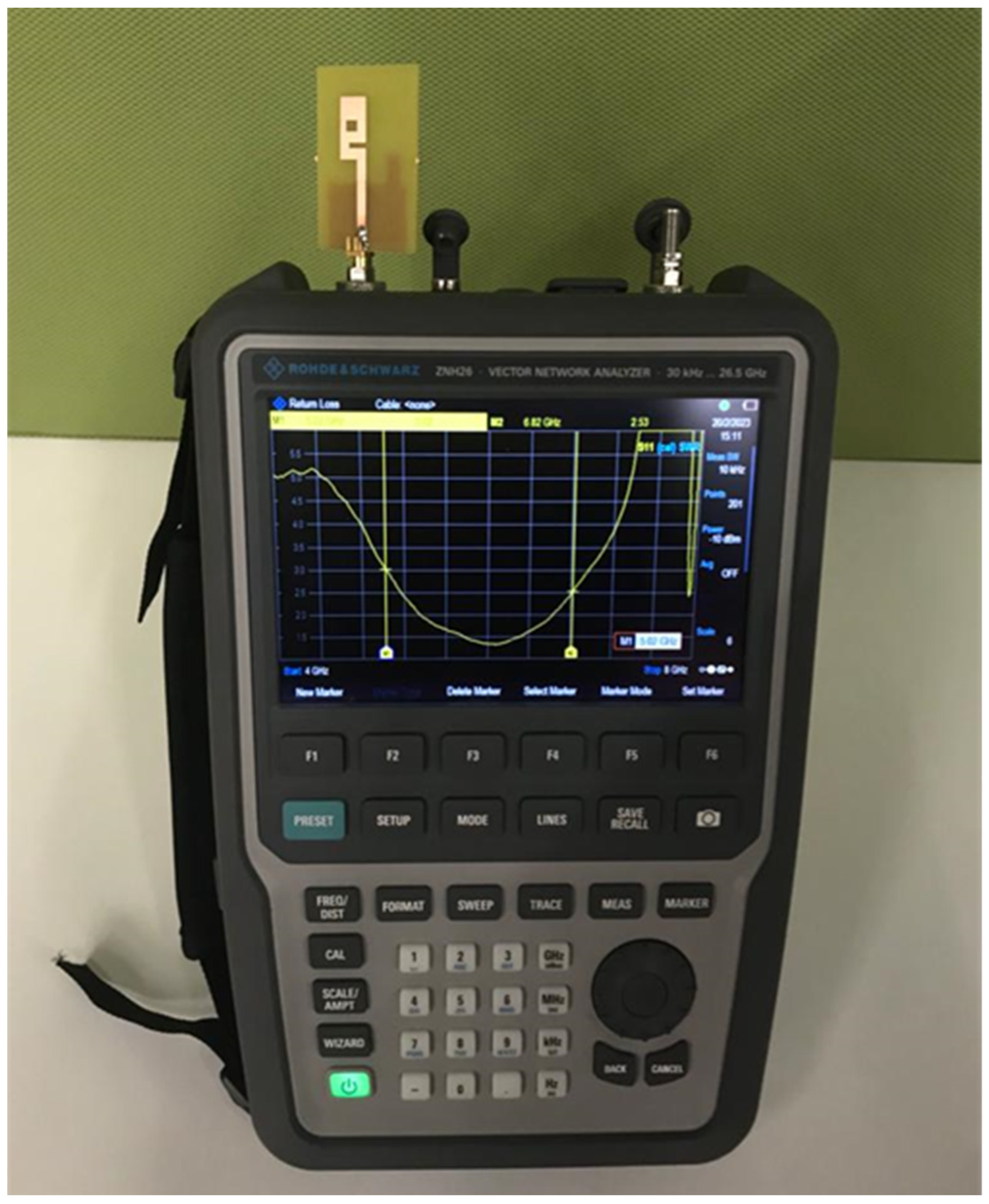
3.1. Return Loss ()
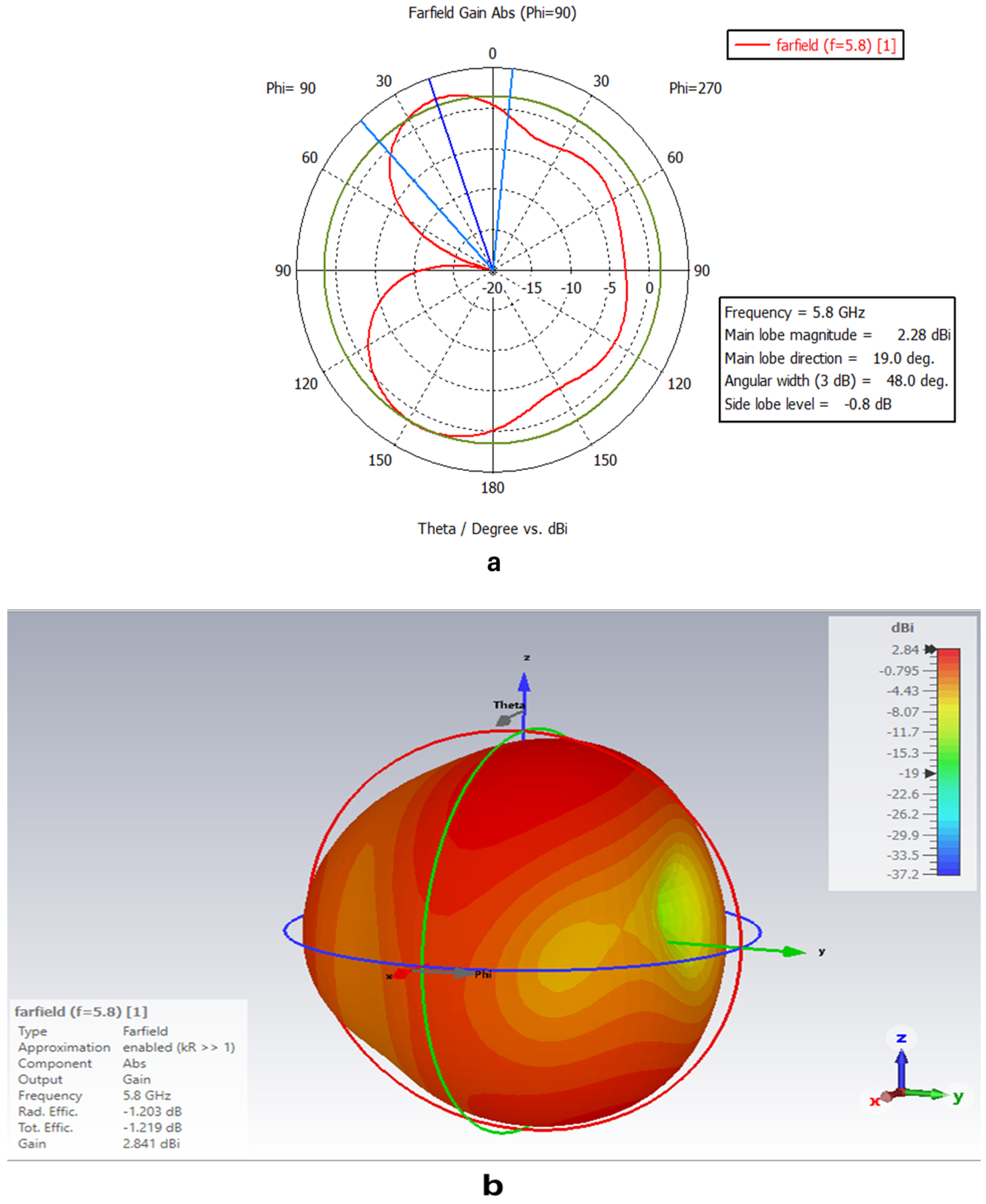
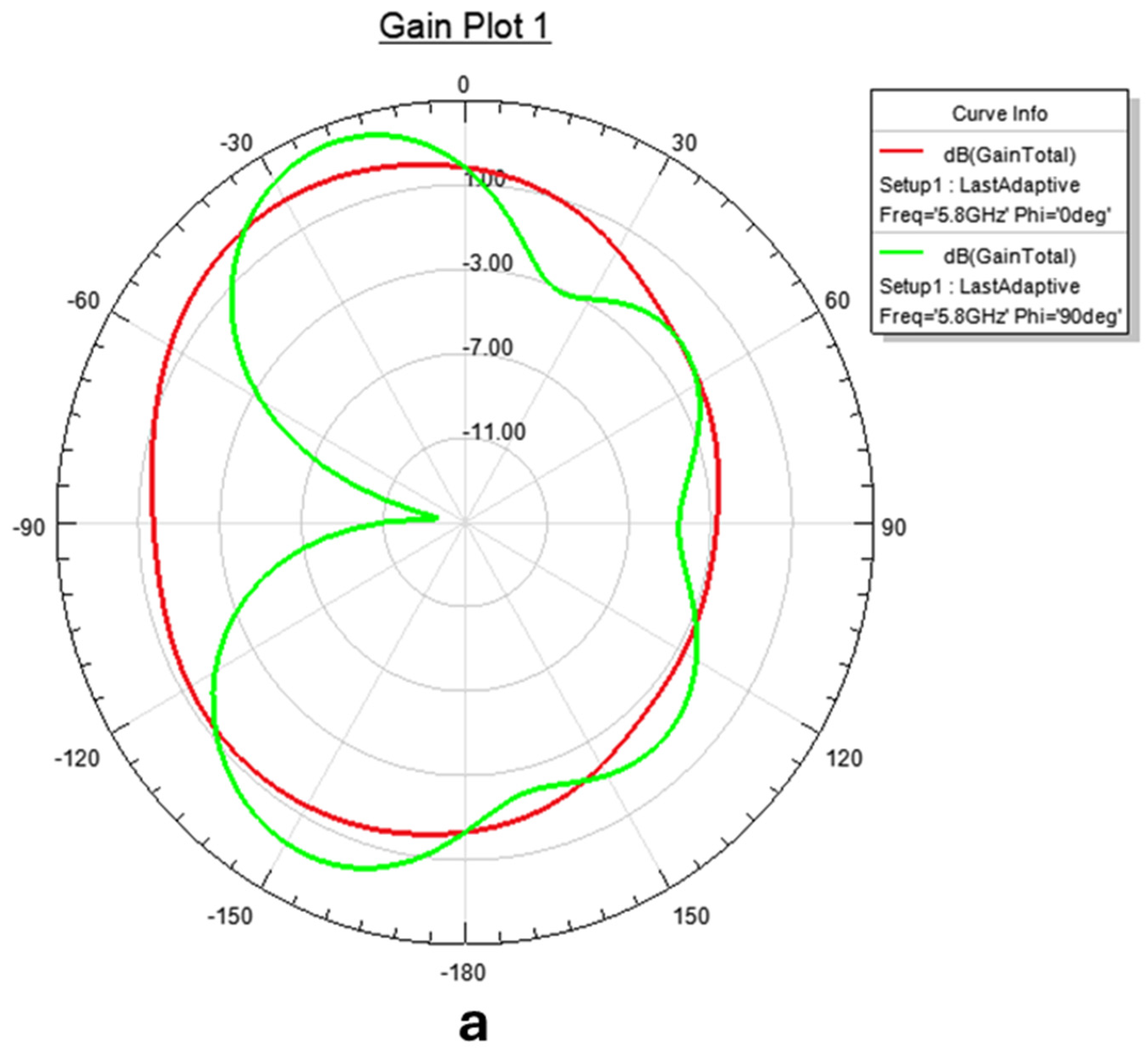
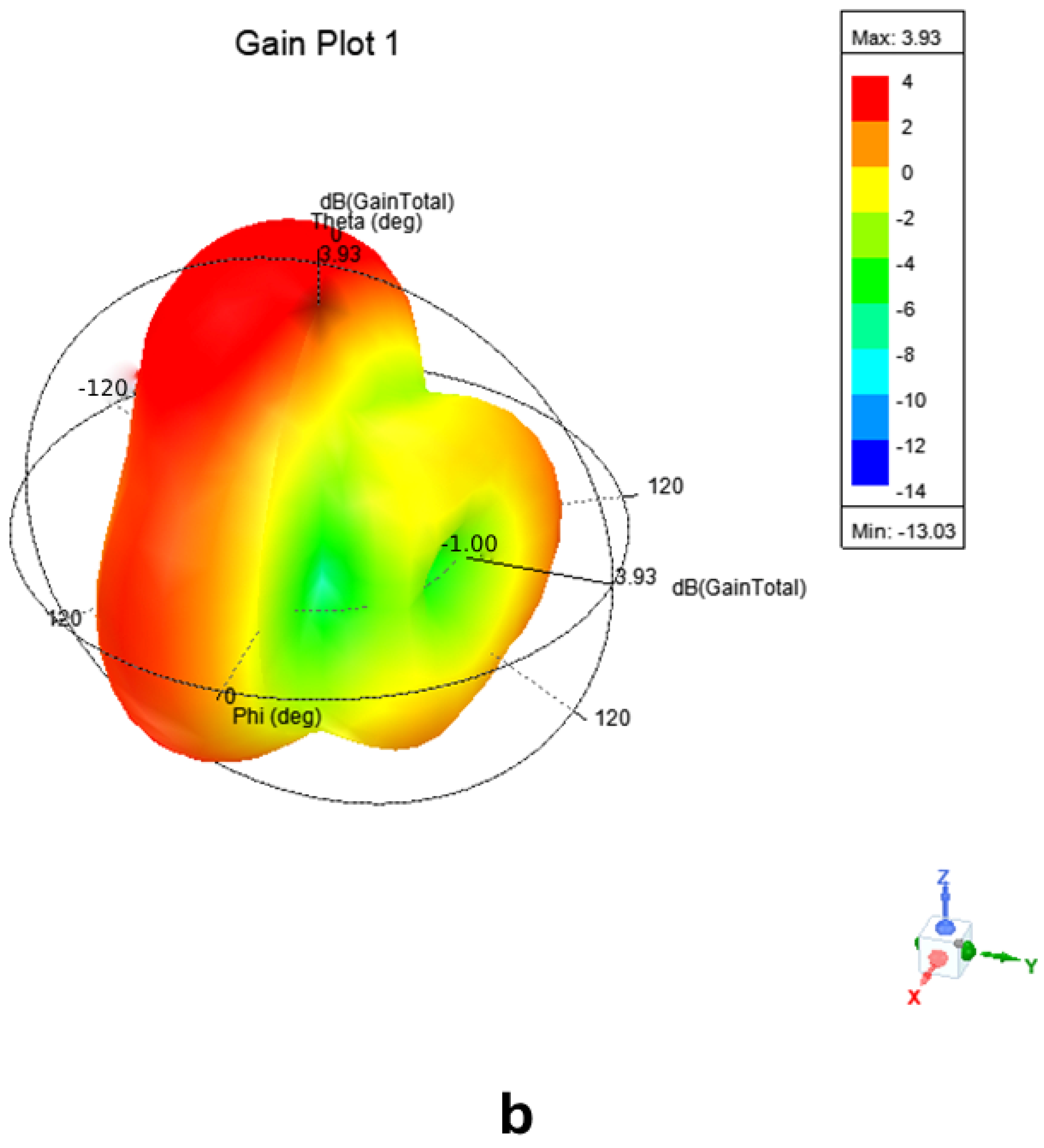
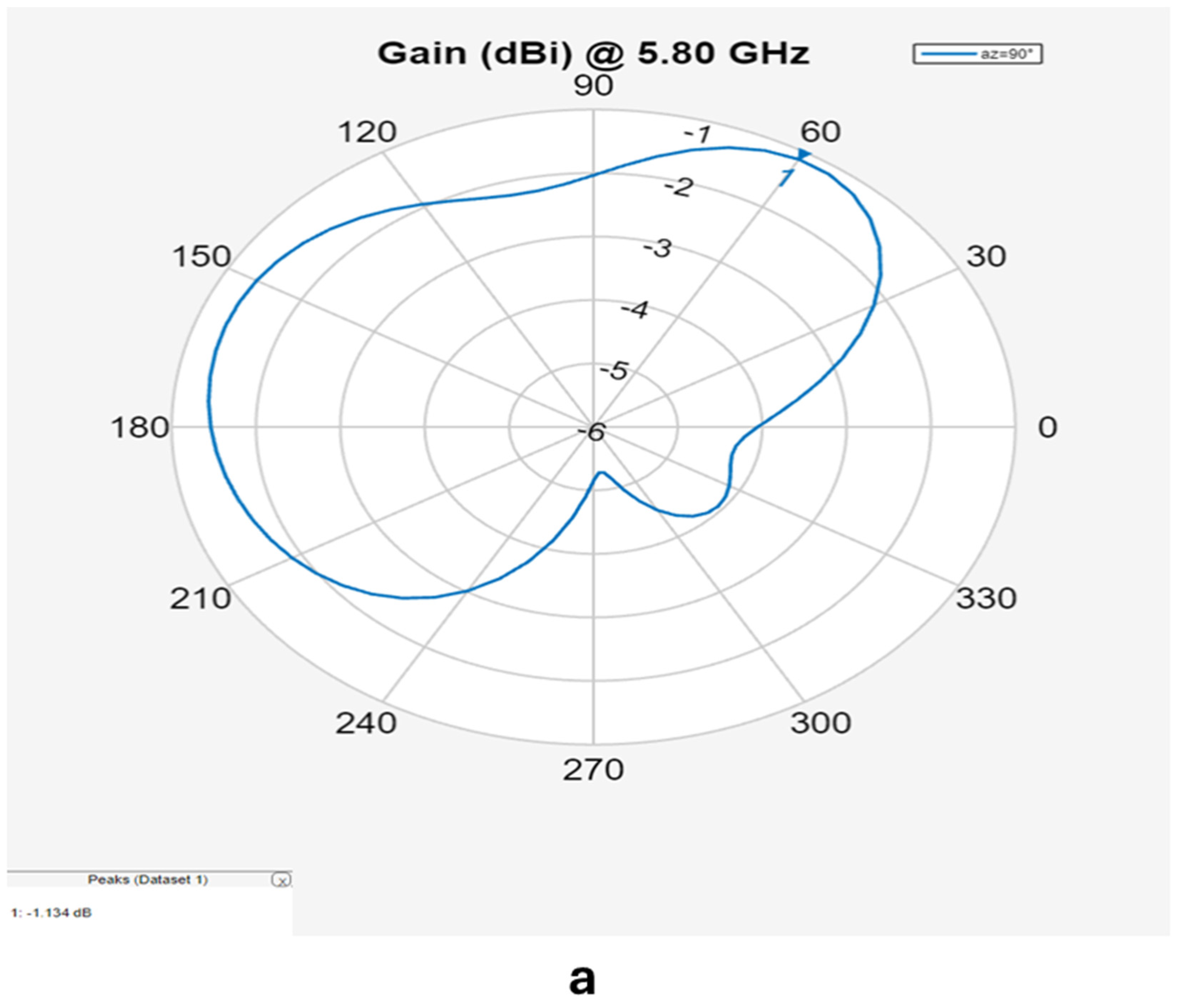
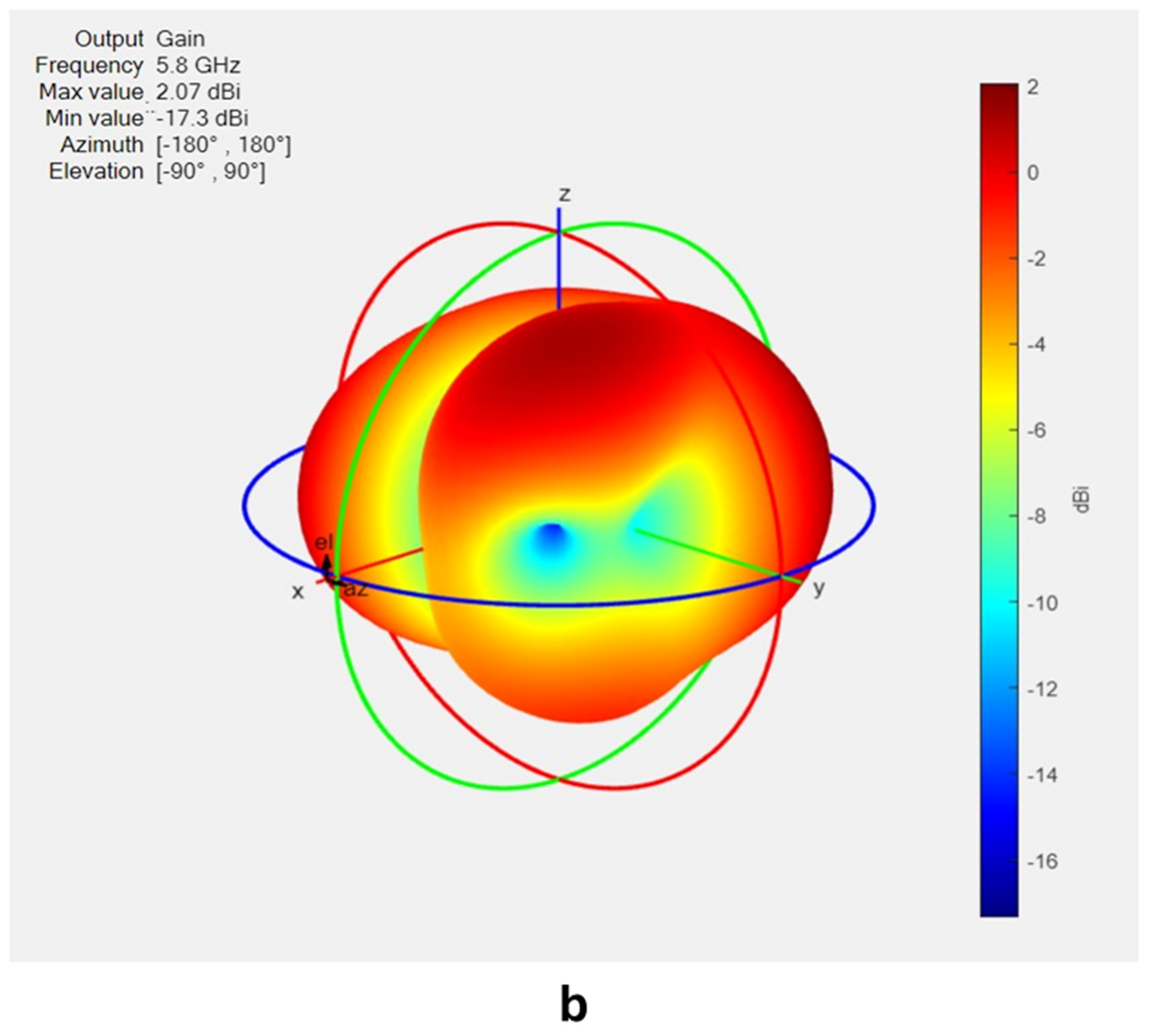
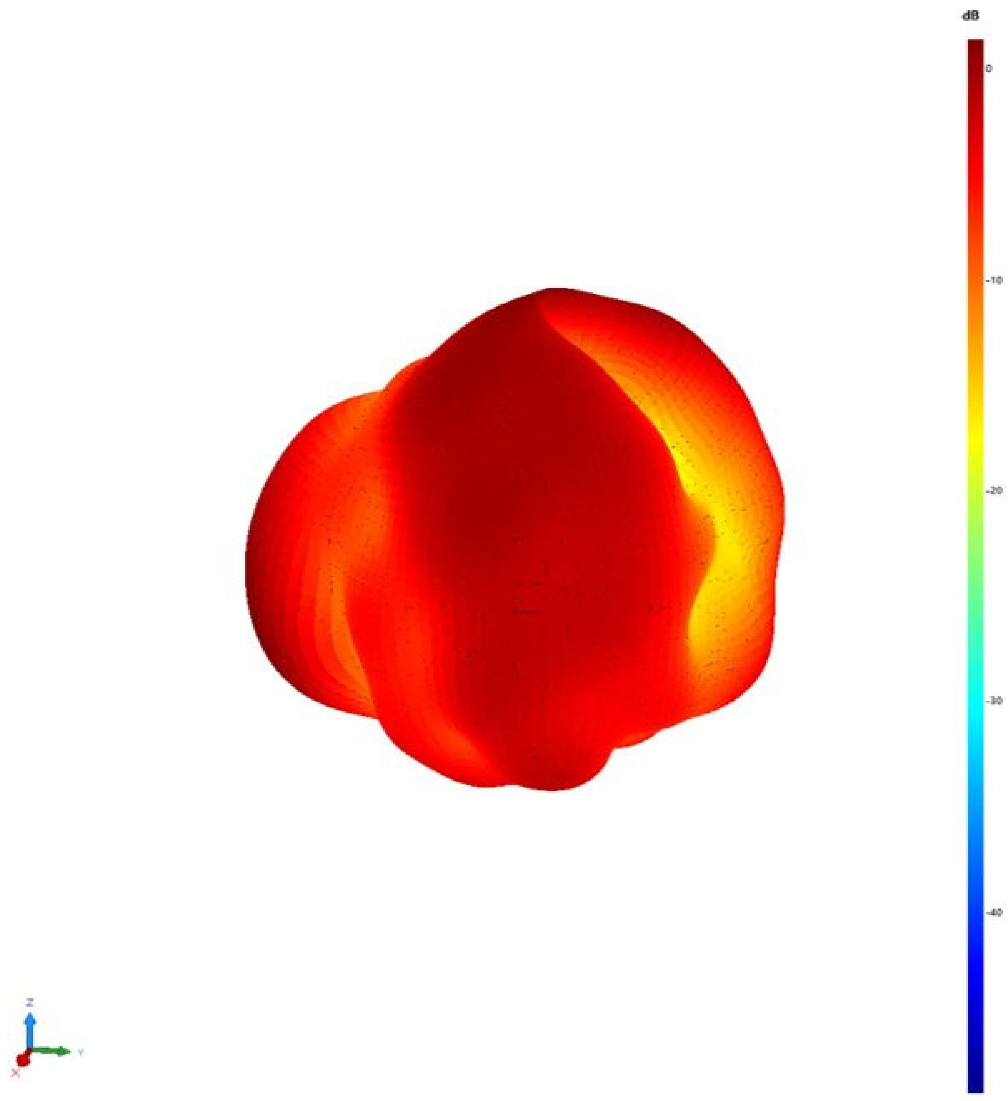
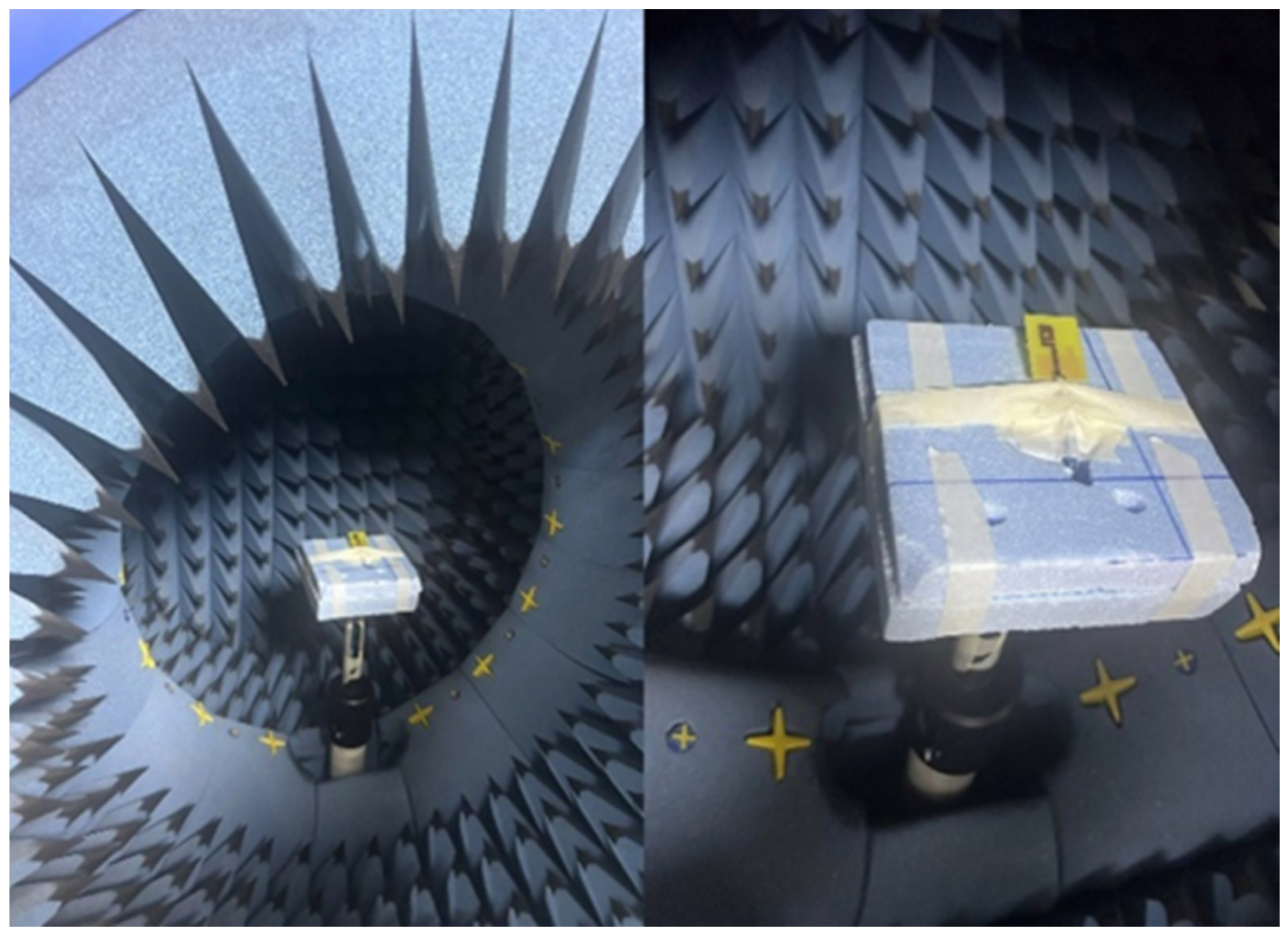
3.2. Radiation Pattern and Gain
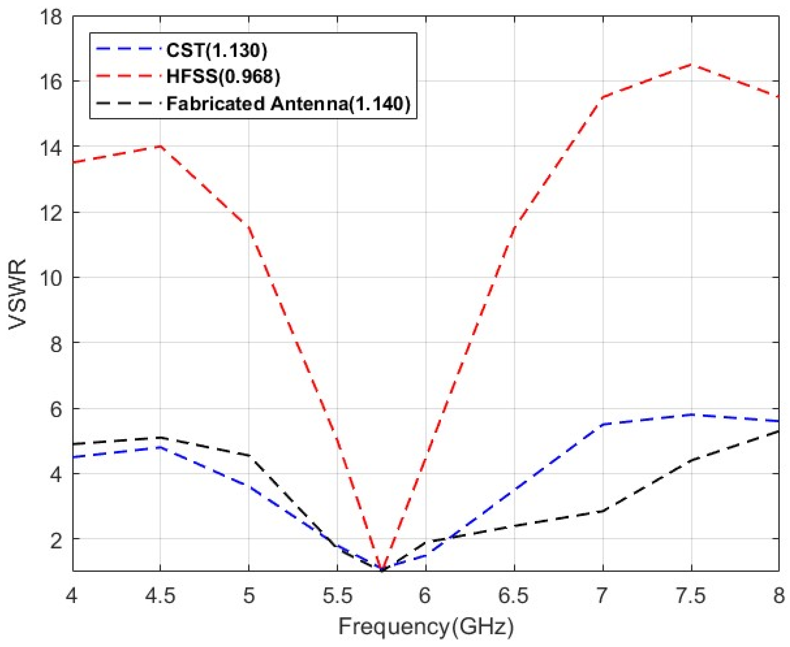
3.3. Voltage Standing Wave Ratio (VSWR)
3.4. Comparison with Previous Works
4. Conclusions
Author Contributions
Funding
Data Availability Statement
Acknowledgments
Conflicts of Interest
References
- Küçükcan, S.; Kaya, A. Dual-Band Microstrip Patch Antenna Design for Wi-Fi Applications. Eur. J. Sci. Technol. 2022, 34, 661–664. [Google Scholar] [CrossRef]
- Gündoğdu, D.Y.; Ertay, A.O.; Enstitüsü, F.B.; Binali, E.; Üniversitesi, Y. Relatively Small, High Isolated Two Port MIMO Antenna Design for Fifth Generation Communication Systems. In Proceedings of the ELECO 2022 International Conference on Electrical and Electronics Engineering Bursa, Turkey 24–26 November 2022. [Google Scholar]
- Fei, Z.C.; Ramli, N.; Jethi, P.L.; Sanossi, T.K.; Rahman, N.H.A. Performance Analysis of Rectangular Microstrip Patch Antenna with Different Substrate Material at 2.4 GHz for WLAN Applications. In Proceedings of the 2021 7th International Conference on Space Science and Communication (IconSpace), Selangor, Malaysia, 23–24 November 2021; pp. 46–49. [Google Scholar] [CrossRef]
- International Telecommunication Union. Intelligent Transport Systems. In Handbook on Land Mobile (Including Wireless Access), 2021st ed.; International Telecommunication Union: Geneva, Switzerland, 2021. [Google Scholar]
- Maddio, S.; Pelosi, G.; Righini, M.; Selleri, S. A compact series array for vehicular communication in the C-band. In Proceedings of the 2019 IEEE International Symposium on Antennas and Propagation and USNC-URSI Radio Science Meeting, Atlanta, GA, USA, 7–12 July 2019; pp. 1337–1338. [Google Scholar]
- Singh, P.; Chaitanya, K.S.; Kumari, R. Microstrip patch antenna for application in intelligent transport systems. In Proceedings of the 2019 TEQIP III Sponsored International Conference on Microwave Integrated Circuits, Photonics and Wireless Networks (IMICPW), Tiruchirappalli, India, 22–24 May 2019; pp. 324–327. [Google Scholar]
- Olaimat, M.M.; Chaouche, Y.B.; El Badawe, M.; Nedil, M.; Ramahi, O.M. Effect of Bending on Metasurface Antenna and Microstrip Patch Antenna Array. In Proceedings of the 2021 IEEE International Symposium on Antennas and Propagation and North American Radio Science Meeting, APS/URSI, Singapore, 4–10 December 2021; pp. 187–188. [Google Scholar] [CrossRef]
- Patwary, A.B.; Abedin, S.; Hossain, M.A. Design of a ladybug shaped circular polarized microstrip antenna at 5.8 GHz as microwave power transmitter to a mav. In Proceedings of the 2019 International Conference on Electrical, Computer and Communication Engineering (ECCE), Cox’sBazar, Bangladesh, 7–9 February 2019; pp. 1–4. [Google Scholar]
- Saini, J.; Agarwal, S.K. Design a single band microstrip patch antenna at 60 GHz millimeter wave for 5G application. In Proceedings of the 2017 International Conference on Computer, Communications and Electronics (Comptelix), Jaipur, India, 1–2 July 2017; pp. 227–230. [Google Scholar]
- Khan, M.M.; Islam, K.; Alam Shovon, N.; Baz, M.; Masud, M. Design of a Novel 60 GHz Millimeter Wave Q-Slot Antenna for Body-Centric Communications. Int. J. Antennas Propag. 2021, 2021, 9795959. [Google Scholar] [CrossRef]
- Roy, S.S.; Naresh, K.M.; Saha, C. Resistively loaded slotted microstrip patch antenna with controllable bandwidth. In Proceedings of the 2016 International Symposium on Antennas and Propagation, APSYM 2016, Cochin, India, 15–17 December 2016; pp. 71–74. [Google Scholar] [CrossRef]
- Sarin, V.P.; Nassar, N.; Deepu, V.; Aanandan, C.; Mohanan, P.; Vasudevan, K. Wideband Printed Microstrip Antenna for Wireless Communications. IEEE Antennas Wirel. Propag. Lett. 2009, 8, 779–781. [Google Scholar] [CrossRef]
- Gürsoy, G.S.; Keskin, S.E.B. Bant Çentik Karakteristiği Gösteren Ultra Geniş Bant Mikroşerit Anten Tasarımları Üzerine Bir İnceleme. Eur. J. Sci. Technol. 2021, 24, 314–320. [Google Scholar] [CrossRef]
- Fan, T.-Q.; Jiang, B.; Liu, R.; Xiu, J.; Lin, Y.; Xu, H. A Novel Double U-Slot Microstrip Patch Antenna Design for Low-Profile and Broad Bandwidth Applications. IEEE Trans. Antennas Propag. 2022, 70, 2543–2549. [Google Scholar] [CrossRef]
- Idris, M.K.; Sarwar, B.; Rehman, Y.; Imeci, T. Rectangular shaped microstrip patch antenna with multiple slits and slots. In Proceedings of the 2017 25th Signal Processing and Communications Applications Conference, SIU 2017, Antalya, Turkey, 15–18 May 2017. [Google Scholar] [CrossRef]
- Shimu, N.J.; Ahmed, A. Design and performance analysis of rectangular microstrip patch antenna at 2.45 GHz. In Proceedings of the 2016 5th International Conference on Informatics, Electronics and Vision, ICIEV 2016, Dhaka, Bangladesh, 13–14 May 2016; pp. 1062–1066. [Google Scholar] [CrossRef]
- Silalahi, L.M.; Budiyanto, S.; Silaban, F.A.; Simanjuntak, I.U.V.; Hendriasari, P.S.; Heryanto. Design of 2.4 GHz and 5.8 GHz Microstrip Antenna on Wi-Fi Network. In Proceedings of the 2020 2nd International Conference on Broadband Communications, Wireless Sensors and Powering (BCWSP), Yogyakarta, Indonesia, 28–30 September 2020; pp. 6–11. [Google Scholar] [CrossRef]
- Venkat, K. Design of Patch Antenna for Ism Band Applications Using Cst Microwave Studio Design and Simulation of Common Feed with Double Microstrip Patch Antenna for Dual Band Satellite Applications View Project Design of Patch Antenna for Ism Band Applications Using Cst Microwave Studio. 2019. Available online: https://www.researchgate.net/publication/360670017 (accessed on 15 December 2023).
- IEEE Standard for Information Technology—Telecommunications and Information Exchange between Systems—Local and Metropolitan Area Networks—Specific Requirements: Part 11: Wireless LAN Medium Access Control (MAC) and Physical Layer (PHY) Specifications: Amendment 6: Wireless Access in Vehicular Environments; Institute of Electrical and Electronics Engineers: New York, NY, USA, 2010; ISBN 978-0-7381-6324-6.
- Modi, A.; Sharma, V.; Rawat, A. Compact Design of Multiband Antenna for IRNSS, Satellite, 4G and 5G Applications. In Proceedings of the 5th International Conference on Computing Methodologies and Communication, ICCMC 2021, Erode, India, 8–10 April 2021; pp. 6–9. [Google Scholar] [CrossRef]
- Narayana, B.L.; Bhavanam, S.N. Design & Simulation of Triple Frequency Triangular Patch Antenna by Using HFSS 14.0. Int. J. Appl. Eng. Res. 2015, 10, 2015. [Google Scholar]
- Institute of Electrical and Electronics Engineers; Institute of Electrical and Electronics Engineers; Morocco Section, Jamiat al-Ḥasan al-Thani. Ecole Normale Supérieure de l’Enseignement Technique de Mohammedia, ICOA 2018 Optimization. In Proceedings of the 2018 International Conference on Optimization and Applications (ICOA), Mohammedia, Morocco, 26–27 April 2018. [Google Scholar]
- Hassan, S.A.; Samsuzzaman, M.; Hossain, M.J.; Akhtaruzzaman, M.; Islam, T. Compact planar UWB antenna with 3.5/5.8 GHz dual band-notched characteristics for IoT application. In Proceedings of the 2017 IEEE International Conference on Telecommunications and Photonics (ICTP), Dhaka, Bangladesh, 26–28 December 2017; pp. 195–199. [Google Scholar]
- Kumar, K.S.; Naik, B.M.; Vahini, S.; Kunooru, B.; Ramakrishna, D. Design of Miniaturized Planar Inverted F Antenna. In Proceedings of the 2022 IEEE 2nd Ukrainian Microwave Week (UkrMW), Kharkiv, Ukraine, 14–18 November 2022. [Google Scholar] [CrossRef]
- Moradi, M.; Sharawi, M.S.; Wu, K. Analytical Model of Guided Waves in Periodically Perforated Dielectric Structure and Its Applications to Terahertz Substrate-Integrated Image Guide (SIIG). IEEE Trans. Microw. Theory Technol. 2023, 71, 4236–4246. [Google Scholar] [CrossRef]
- Hassan, R.; Eldayasti, S.K.; Aboul-Dahab, M.A. Design of a Compact, Dual-band, and Single-Fed Patch Antenna for 5G Applications. In Proceedings of the 2023 5th International Youth Conference on Radio Electronics, Electrical and Power Engineering (REEPE), Moscow, Russia, 16–18 March 2023; pp. 1–6. [Google Scholar] [CrossRef]
- Sifat, R.; Faruque, M.R.I.; Ramachandran, T.; Abdullah, M.; Islam, M.T.; Al-Mugren, K.S. Development of double-layer metamaterial with high effective medium ratio values for S-and C-band applications. Heliyon 2024, 10, e23851. [Google Scholar] [CrossRef] [PubMed]
- Islam, R.; Mahbub, F.; Akash, S.B.; Prince, I.A.; Tasnim, F.; Navia, N.T. Design of a Compact Circular Patch Antenna Operating at ISM-Band for the WiMAX Communication Systems. In Proceedings of the 10th IEEE International Conference on Communication, Networks and Satellite, Comnetsat 2021, Purwokerto, Indonesia, 17–18 July 2021; pp. 358–362. [Google Scholar] [CrossRef]
- Mahbub, F.; Islam, R.; Al-Nahiun, S.A.K.; Akash, S.B.; Hasan, R.R.; Rahman, M.A. A Single-Band 28.5GHz Rectangular Microstrip Patch Antenna for 5G Communications Technology. In Proceedings of the 2021 IEEE 11th Annual Computing and Communication Workshop and Conference, CCWC 2021, Online, 27–30 January 2021; pp. 1151–1156. [Google Scholar] [CrossRef]
- Rahman, T.; Zhaowen, Y.; Youcef, H. A dual band monopole microstriop printed antenna for WLAN (2.4/5.2/5.8 GHz) application. In Proceedings of the ICMTCE 2013—2013 IEEE International Conference on Microwave Technology and Computational Electromagnetics, Qingdao, China, 25–28 August 2013; pp. 204–207. [Google Scholar] [CrossRef]
- Al Ka’Bi, A. Design of a Microstrip Dual Band Fractal Antenna for Mobile Communications. In Proceedings of the 2022 IEEE International Black Sea Conference on Communications and Networking, BlackSeaCom 2022, Sofia, Bulgaria, 6–9 June 2022; pp. 85–90. [Google Scholar] [CrossRef]
- Shafqat, A.; Tahir, F.A. Miniaturized Tapered Meandered Dual Band Dipole Antenna for WiFi 2.4/5.8 GHz Application. In Proceedings of the Progress in Electromagnetics Research Symposium-Fall (PIERS-FALL), Singapore, 19–22 November 2017. [Google Scholar]
- Naji, D.K. Miniature Slotted Semi-Circular Dual-Band Antenna for WiMAX and WLAN Applications. J. Electromagn. Eng. Sci. 2020, 20, 115–124. [Google Scholar] [CrossRef]
- Tak, J.; Woo, S.; Kwon, J.; Choi, J. Dual-Band Dual-Mode Patch Antenna for On-/Off-Body WBAN Communications. IEEE Antennas Wirel. Propag. Lett. 2016, 15, 348–351. [Google Scholar] [CrossRef]
- Singh, A.K.; Abegaonkar, M.P.; Koul, S.K. Miniaturized Multiband Microstrip Patch Antenna Using Metamaterial Loading for Wireless Application. Prog. Electromagn. Res. C 2018, 83, 71–82. [Google Scholar] [CrossRef]
- Selvam, Y.P.; Elumalai, L.; Alsath, M.G.N.; Kanagasabai, M.; Subbaraj, S.; Kingsly, S. Novel Frequency- and Pattern-Reconfigurable Rhombic Patch Antenna with Switchable Polarization. IEEE Antennas Wirel. Propag. Lett. 2017, 16, 1639–1642. [Google Scholar] [CrossRef]
- Adamantia, C.; Locke, J.F.; Papapolymerou, J. Vehicle platform effects on performance of flexible, lightweight, and dual-band antenna for vehicular communications. IEEE J. Microw. 2021, 2, 123–133. [Google Scholar]
- Jouini, A.; Hasnaoui, S.; Cherif, A. Comparative Study of patch antennas for C-V2x Communication. In Proceedings of the 2022 5th International Conference on Advanced Systems and Emergent Technologies (IC_ASET), Hammamet, Tunisia, 22–25 March 2022. [Google Scholar]
- Durgun, A.C.; Balanis, C.A.; Birtcher, C.R.; Allee, D.R. Design, Simulation, Fabrication and Testing of Flexible Bow-Tie Antennas. IEEE Trans. Antennas Propag. 2011, 59, 4425–4435. [Google Scholar] [CrossRef]


| Step 1 | : To calculate patch width |
| Step 2 | : Effective Dielectric Constant |
| Step 3 | : Extended length of the patch |
| Step 4 | : To calculate the length of the patch |
| W1 = 35 | W6 = 6 | L2 = 25 | L8 = 18.6 |
| W2 = 17.5 | W7 = 28 | L3 = 16.8 | L9 = 8 |
| W3 = 3 | W8 = 21 | L4 = 6.3 | |
| W4 = 4 | W9 = 5 | L6 = 3 | |
| W5 = 9 | L1 = 50 | L7 = 1.5 |
| Antenna | Dimension | Frequency Band (GHz) and Bandwidth (MHz) | Gain (dB) |
|---|---|---|---|
| [30] | 36 × 32 × 1.6 FR-4 | 5.75 (740) | 1.45 |
| [31] | 54.44 × 70.7 × 1.6 FR-4 | 5.8 (410) | 2.21 |
| [17] | 50 × 50 × 1.6 FR-4 | 5.8 (770) | 3.57 |
| [32] | 21.5 × 15 × 1.6 FR-4 | 5.71 (570) | 2.45 |
| [33] | 17 × 18 × 0.8 FR-4 | 5.8 (150) | 1.84 |
| [34] | 30 × 45 × 3.2 FR-4 | 5.8 (160) | 1.59 |
| [35] | 19 × 19 × 0.76 Neltec | 5.8 (≤200) | 3.1 |
| [36] | 60 × 50 × 1.6 FR-4 | 5.81 (196) | 3 |
| [37] | 91.5 × 30 × 0.1 Rogers 3850 | 5.9 (440) | 1.6 |
| [38] | 31.76 × 34.39 × 2.03 FR-4 | 5.9 (More than one design) | (More than one design) |
| Proposed Antenna | 35 × 50 × 1.6 FR-4 | 5.8 (550) | 3.93 |
Disclaimer/Publisher’s Note: The statements, opinions and data contained in all publications are solely those of the individual author(s) and contributor(s) and not of MDPI and/or the editor(s). MDPI and/or the editor(s) disclaim responsibility for any injury to people or property resulting from any ideas, methods, instructions or products referred to in the content. |
© 2024 by the authors. Licensee MDPI, Basel, Switzerland. This article is an open access article distributed under the terms and conditions of the Creative Commons Attribution (CC BY) license (https://creativecommons.org/licenses/by/4.0/).
Share and Cite
Guneser, M.T.; Seker, C.; Guler, M.I.; Fitriyani, N.L.; Syafrudin, M. Efficient 5.8 GHz Microstrip Antennas for Intelligent Transportation Systems: Design, Fabrication, and Performance Analysis. Mathematics 2024, 12, 1202. https://doi.org/10.3390/math12081202
Guneser MT, Seker C, Guler MI, Fitriyani NL, Syafrudin M. Efficient 5.8 GHz Microstrip Antennas for Intelligent Transportation Systems: Design, Fabrication, and Performance Analysis. Mathematics. 2024; 12(8):1202. https://doi.org/10.3390/math12081202
Chicago/Turabian StyleGuneser, Muhammet Tahir, Cihat Seker, Mehmet Izzeddin Guler, Norma Latif Fitriyani, and Muhammad Syafrudin. 2024. "Efficient 5.8 GHz Microstrip Antennas for Intelligent Transportation Systems: Design, Fabrication, and Performance Analysis" Mathematics 12, no. 8: 1202. https://doi.org/10.3390/math12081202
APA StyleGuneser, M. T., Seker, C., Guler, M. I., Fitriyani, N. L., & Syafrudin, M. (2024). Efficient 5.8 GHz Microstrip Antennas for Intelligent Transportation Systems: Design, Fabrication, and Performance Analysis. Mathematics, 12(8), 1202. https://doi.org/10.3390/math12081202