Article

Study on the Vibration Characteristics of the Helical Gear-Rotor-Bearing Coupling System of a Wind Turbine with Composite Faults

School of Automotive and Transportation, Shenyang Ligong University, Shenyang 110159, China
*
Author to whom correspondence should be addressed.
Mathematics 2024, 12(9), 1410; https://doi.org/10.3390/math12091410
Submission received: 13 April 2024 / Revised: 30 April 2024 / Accepted: 2 May 2024 / Published: 4 May 2024
(This article belongs to the Special Issue Applied Mathematical Modeling and Intelligent Algorithms)

Abstract

:
As the core component of the wind turbine generation gearbox, the gear-rotor-bearing transmission system typically operates in harsh environments, inevitably leading to the occurrence of composite faults in the system, which exacerbates system vibration. Therefore, it is necessary to study the vibration characteristics of wind turbine helical gear-rotor-bearing transmission systems with composite faults. This paper uses an improved energy method to calculate the theoretical time-varying mesh stiffness of a helical gear with a root crack failure. On the premise of considering the time-varying meshing stiffness of the faulty helical gear, the gear eccentric fault, and the nonlinear support force of the faulty bearing, a multi-degree-of-freedom helical gear-rotor-bearing transmission system with compound faults was established by using the lumped parameter method. The dynamic model of the system was solved based on the Runge–Kutta method, and the vibration response of the system under healthy conditions, single faults with gear eccentricity, single faults with tooth root cracks, and coupled bearing composite faults were simulated and analyzed. The results show that the simulation results based on KISSsoft software 2018 version verify the effectiveness of the improved energy method; the existence of single faults and composite faults will cause the fault characteristics in the time domain and frequency domain responses. In this paper, the influence of a single fault and a complex fault on the time domain and frequency domain of the system is mainly discovered through the fault study of the helical rotor-bearing system, and the influence of the fault degree on the vibration of the gear motion system is discussed. The greater the degree of the fault, the more vibration of the system occurs; accordingly, when the system is under the coupling of tooth root crack and bearing fault, there is a significant difference compared with the healthy system and the single fault system. The system vibration has obvious time domain and frequency domain signal characteristics, including periodic pulse impacts caused by gear faults and time domain impact caused by bearing. The fault characteristic frequencies can also be found in the frequency domain. In this paper, the fault study of a helical gear of wind turbine generation provides a reference for the theoretical analysis of the vibration characteristics of the helical gear-rotor-bearing system under various fault conditions, lays a solid foundation for the simulation and subsequent diagnosis of the composite fault signal of the system, and provides help for the fault diagnosis of wind turbine gearboxes in the future.

1. Introduction

As one of the most widely used power and motion transmission devices in various mechanical equipment, the gear-rotor-bearing transmission system plays a vital role in the automotive, marine, aerospace, wind turbine, and other industries [1]. With the continuous development of modern industry, gears are developing towards high speed and heavy loads. Due to the poor working environment of the gear-rotor-bearing transmission system and influenced by various internal and external excitations, it is easy to cause the failure of the gear, shaft, bearing, and other components in the system, aggravate the vibration of the system, thereby reducing the transmission performance and the life of the system.
According to statistics, the faults of the wind turbine gearbox transmission system are mainly caused by gear faults, accounting for about 60% [2], followed by bearings and shafts [3]. The coupling relationship between gear pairs and bearings in the transmission system is likely to cause composite faults in the system [4,5], resulting in extremely complex vibration characteristics and increasing the difficulty of fault identification. Therefore, considering the influence of various excitations in the transmission system, it is of great significance to establish the dynamic model of the high-speed gear-rotor-bearing transmission system of the wind turbine gearbox with composite faults, analyze the vibration characteristics of the wind turbine gear transmission system with composite faults, and provide a theoretical basis for the design of the wind turbine gearbox and the diagnosis of composite faults.
Accurately calculating the time-varying meshing stiffness of gears with faults is the key to studying gear dynamics, and the potential energy method is generally used to solve the time-varying meshing stiffness of helical gears with faults. Yang and Lin [6] first proposed a method for calculating gear meshing stiffness using the potential energy method. Wu et al. [7] introduced linear cracks in the Yang model and calculated the time-varying meshing stiffness of gears with root crack faults. Afterward, Wan et al. [8] considered the variability of crack length and proposed a potential energy method based on the slicing idea to calculate the time-varying meshing stiffness of helical gears with crack faults. Ma [9] considers the spur gear teeth as a cantilever beam starting from the root circle and proposes an improved calculation method for time-varying meshing stiffness. Huang et al. [10,11] considered helical gears with spatial cracks and improved the calculation method for the time-varying meshing stiffness of faulty helical gears.
For the study of the dynamic characteristics of faulty gears, Choy et al. [12] developed a gear dynamics simulation program that can simulate and analyze gear transmission systems with tooth surface pitting, wear, and local tooth breakage. Ian Howard et al. [13] used a finite element model to calculate the meshing stiffness of gear with root cracks and introduced friction to study the effects of root cracks and friction on the dynamic response of gear systems. Afterward, he [14] established a 26-degree-of-freedom gear dynamics model for a two-stage straight cylindrical gear transmission, which was used to compare and study gear pitting and crack faults. Ma et al. [15] published a review of dynamic analysis of gear transmission systems under root crack faults, summarizing the classification of crack evolution paths in gear meshing pairs and summarizing crack faults in gear transmission systems using time-varying meshing stiffness calculation methods. Wan et al. [16] used the improved potential energy method to solve the time-varying meshing stiffness of spur gears with crack faults. A 10-degree-of-freedom vibration dynamic model of spur gear-rotor side-torsion coupling with a crack fault was established, and the vibration response of the system was simulated. Han et al. [17] considered tooth surface peeling and local damage, revealing the impact of gear pair meshing stiffness on single or multiple faulty teeth. Then, an 8-degree-of-freedom spur gear dynamic model with composite faults was established, and the dynamic responses under various fault states were solved and analyzed. Ma et al. [18] established a dynamic model of a 12-degree-of-freedom primary gearbox gear-rotor coupling system and studied the effects of crack depth, width, initial position, and crack propagation direction on the time-domain and frequency-domain fault characteristics and statistical indicators of the system. The fault characteristics were verified through experiments. Cui et al. [19] considered tooth backlash, time-varying meshing stiffness, and bearing radial clearance and established a nonlinear dynamic model of a gear-bearing flexible shaft system considering internal breathing cracks and gear tooth wear. The effects of tooth backlash, shaft cracks, and gear tooth wear on the nonlinear dynamic behavior of the gear-bearing system were studied. However, most scholars focus on single faulty gears, and few papers have studied the dynamic response of gear systems with composite faults. For the study of gear dynamics with composite faults, Liang and Zuo [20] published a review on gear fault dynamic modeling, in which they pointed out that establishing more efficient and accurate dynamic models containing composite faults is an important task for future gear dynamics research. Zhao et al. [21] took into account that it is difficult to identify the faults with weak signals in a multistage gear transmission system that contains multiple faults in the case of coupled faults and established a fixed-axis nonlinear dynamics model of the coupled faults of gear crack and planetary gear broken teeth, obtained the fault frequency characteristics of the system with the change of excitation frequency, and by comparing the theoretical and experimental signals, obtained the intrinsic frequency of the system, the side frequency characteristics of the single faults, and the coupled faults. Cao et al. [22] proposed a time-varying mesh stiffness calculation method for the fatigue cracks and wear-coupled faults, then combined them with the coupled fault evolution model and established the coupled fault evolution model. A coupled fault evolution model was established, and a coupling fault evolution dynamics model was constructed by bringing the obtained coupled fault meshing stiffness into the model of an 8-degree-of-freedom spur gear drive system as a fault excitation. Dai et al. [23] constructed a 36-degree-of-freedom dynamics model of a spur gear-axle-bearing system and simulated the system response under the conditions of a single fault containing tooth spalling, a single fault of the bearing inner ring, and the composite fault state of the two, respectively. The response of the system was simulated and analyzed based on the spectrogram of the response, and finally, the correctness of the model was verified using experiments.
In response to the research on the dynamic characteristics of faulty ball bearings, Patel et al. [24] established a dynamic model of deep groove ball bearings considering single and multiple defects on the inner and outer surfaces of the bearing and obtained the coupling solution of the control equation. Patel et al. [25] established a 9-degree-of-freedom model of a composite defect cylindrical roller bearing rotor system consisting of an inner and outer ring with one defect each and solved the nonlinear contact force of the bearing. Seyed et al. [26] conducted simulation and experimental analysis on angular contact ball bearings with defects in the outer ring. And model and solve bearings without or with outer ring defects. At the same time, the vibration response under different rotational speeds and axial preload conditions was simulated. On the basis of the quasi-static model of bearings, Cheng et al. [27] introduced a local contour function for the depth and circumferential variation range of local defects and established a quasi-static analysis model of bearings considering local defects. Ogundare et al. [28] provided a background for effective planetary bearing failure analysis in the SA330 helicopter main gearbox by studying the characteristics of planetary stars and some important frequency components that are crucial for fault feature extraction.
It is not difficult to find that most of the current literature has insufficient research on the improved calculation of meshing stiffness of helical gears with root crack faults, and most of the literature only focuses on the vibration characteristics of a single-fault system of gears and bearings; however, the vibration characteristics of helical gear-rotor-bearing coupling systems with compound faults are rarely studied. To address the above issues, in this paper, the time-varying meshing stiffness of helical gears with root crack faults is calculated based on the improved energy method, and mathematical models of the nonlinear support forces of angular contact ball bearings under several typical fault forms are established. Under the premise of fully considering the various excitations in the helical gear system and the nonlinear supporting force of the bearing, a 22-degree-of-freedom dynamic model of the helical gear-rotor-bearing transmission system with composite faults was established based on the lumped parameter method, and the vibration response of the helical gear-rotor-bearing transmission system under various fault conditions was studied, and the influence of fault parameters on the system response was analyzed.

2. Calculation of Meshing Stiffness of Helical Gears with Root Cracks Based on Improved Energy Method

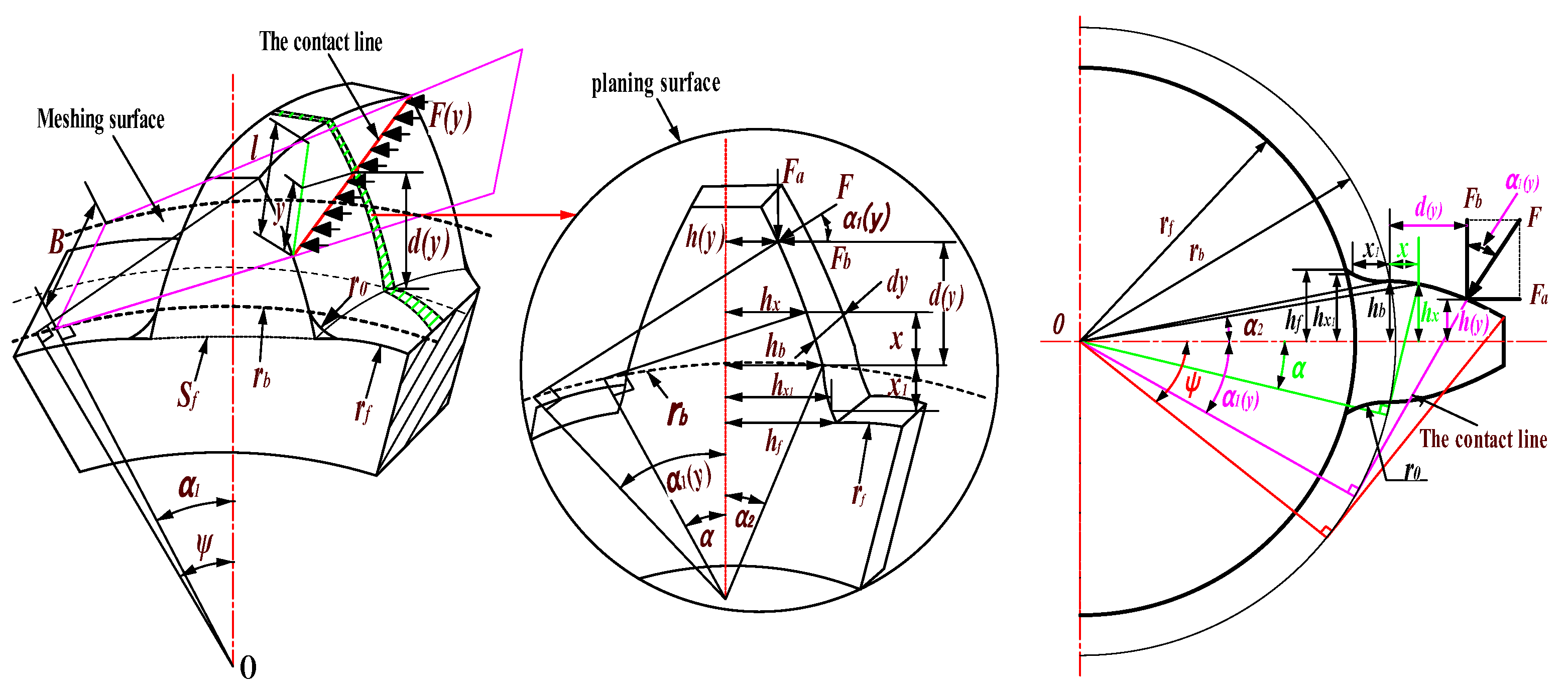
In this paper, we propose an improved calculation method for time-varying meshing stiffness of faulty helical gears containing root cracks. For spur gears, each tooth can be regarded as a cantilever beam of variable cross-section, which is deformed under the action of tooth surface load, and the cantilever beam model of variable cross-section for spur gears is shown in Figure 1. The time-varying meshing stiffness of gears consists of five parts: Hertz contact stiffness k h , bending stiffness k b , shear stiffness k s , axial compression stiffness k a , and elastic stiffness of the matrix k f . The stiffness of each part can be expressed by Equations (1)–(5):
k h = F 2 2 U h = π E B 4 1 u 2
k b = F 2 2 U b = 1 0 d d x cos α 1 h sin α 1 2 E I x dx
k s = F 2 2 U s = 1 0 d 1.2 cos 2 α 1 G A x dx
k a = F 2 2 U a = 1 0 d sin 2 α 1 E A x dx
k f = 1 cos 2 α 1 E B L u f S f 2 + M u f S f + P 1 + Q tan 2 α 1
where U h , U b , U s , U a are Hertz contact deformation potential energy, bending deformation potential energy, shear deformation potential energy, and axial deformation potential energy, respectively. F is the meshing force in the meshing line direction. E , G , and μ are Young’s modulus, shear modulus, and Poisson ratio, respectively. The significance of the representation of the remaining parameters and the derivation process of their calculation formulas are described in detail in the literature [8] and will not be repeated in this paper. According to the above equation, the integrated meshing stiffness of a pair of spur gear cassettes can be obtained, as shown in Equation (6).
k t = i = 1 n 1 1 k h , i + 1 k b 1 , i + 1 k s 1 , i + 1 k a 1 , i + 1 k f 1 , i + 1 k b 2 , i + 1 k s 2 , i + 1 k a 2 , i + 1 k f 2 , i
Helical gears are calculated quite differently from spur gears due to the presence of helix angles. In this paper, based on the previous work, the idea of converting helical gears into a number of spur gears and integrating them along the contact line is still used to solve the time-varying mesh stiffness of helical gears by using the slicing method and the cumulative summation method. The case that the tooth root circle of the helical gear does not coincide with the base circle is considered, and the tooth root transition circle angle is also considered, and then the energy method formula is improved. When the radius of the base circle is larger than the radius of the tooth root circle, the three-dimensional and two-dimensional models of the helical gear variable-section cantilever beam are shown in Figure 2.
Based on the modified cantilever beam model for helical gears and the previous equations, the improved gear-slicing bending potential can be derived with the expression of Equation (7):
k b = 0 l d y 1.5 E α 1 y α 2 1 + cos α 1 y α 2 α sin α cos α 2 α 2 α cos α sin α + α 2 α cos α 3 d α + 0 r b r f 1.5 d y + x 1 cos α 1 y h y sin α 1 y 2 2 E h x 1 3 d x 1
where h x 1 is the distance between a point of the root transition curve and the gear centerline, h x 1 = h b + r 0 r 0 2 x 1 2 , r 0 is the radius of the root transition curve, h b = r b sin α 2 .
Since Equation (7) cannot be solved directly for indefinite integrals, the idea of cumulative summation, the bending stiffness k b of the helical gear can be re-expressed as:
k b = j = 1 N 1 1.5 E α 1 α 2 1 + cos α 1 α 2 α sin α cos α 2 α 2 α cos α sin α + α 2 α cos α 3 Δ y d α + 0 r b r f 1.5 d y + x 1 cos α 1 h y sin α 1 2 2 E h x 1 3 d x 1
Similar to the process of solving the bending stiffness k b , the shear stiffness k s and axial compression stiffness k a of helical gears are:
k s = j = 1 N 1 1.2 E α 1 α 2 ( 1 + ν ) ( α 2 α ) cos α cos 2 α 1 sin α + ( α 2 α ) cos α Δ y d α + 0 r b r f 1.2 cos 2 α G A x 1 d x 1
k a = j = 1 N 1 0.5 E α 1 α 2 ( 1 + ν ) ( α 2 α ) cos α sin 2 α 1 sin α + ( α 2 α ) cos α Δ y d α + 0 r b r f sin 2 α E A x 1 d x 1
When the radius of the base circle is smaller than the radius of the root circle, the two-dimensional and three-dimensional models of the inclined gear tooth cantilever beam slices are shown in Figure 3.
At this point, the bending stiffness k b , shear stiffness k s , and axial compression stiffness k a of the corrected helical gear are expressed by:
k b = j = 1 N 1 1.5 E α 1 f ( α ) 1 + cos α 1 α 2 α sin α cos α 2 α 2 α cos α sin α + α 2 α cos α 3 Δ y d α
k s = j = 1 N 1 1.2 E α 1 f ( α ) ( 1 + ν ) ( α 2 α ) cos α cos 2 α 1 sin α + α 2 α cos α Δ y d α
k a = j = 1 N 1 0.5 E α 1 f ( α ) ( 1 + ν ) ( α 2 α ) cos α sin 2 α 1 sin α + α 2 α cos α Δ y d α
where:
f α = α 3 r f cos ( α 4 ) r b α 4 r f cos ( α 4 ) < r b
α 3 = α f ( π 2 z + i n v α i n v α f )
α 4 = ( π 2 z + i n v α i n v α f )
where α f is the root circle pressure angle. The k h and k f of helical gears are constant regardless of the relationship between the size of the root circle and the base circle.
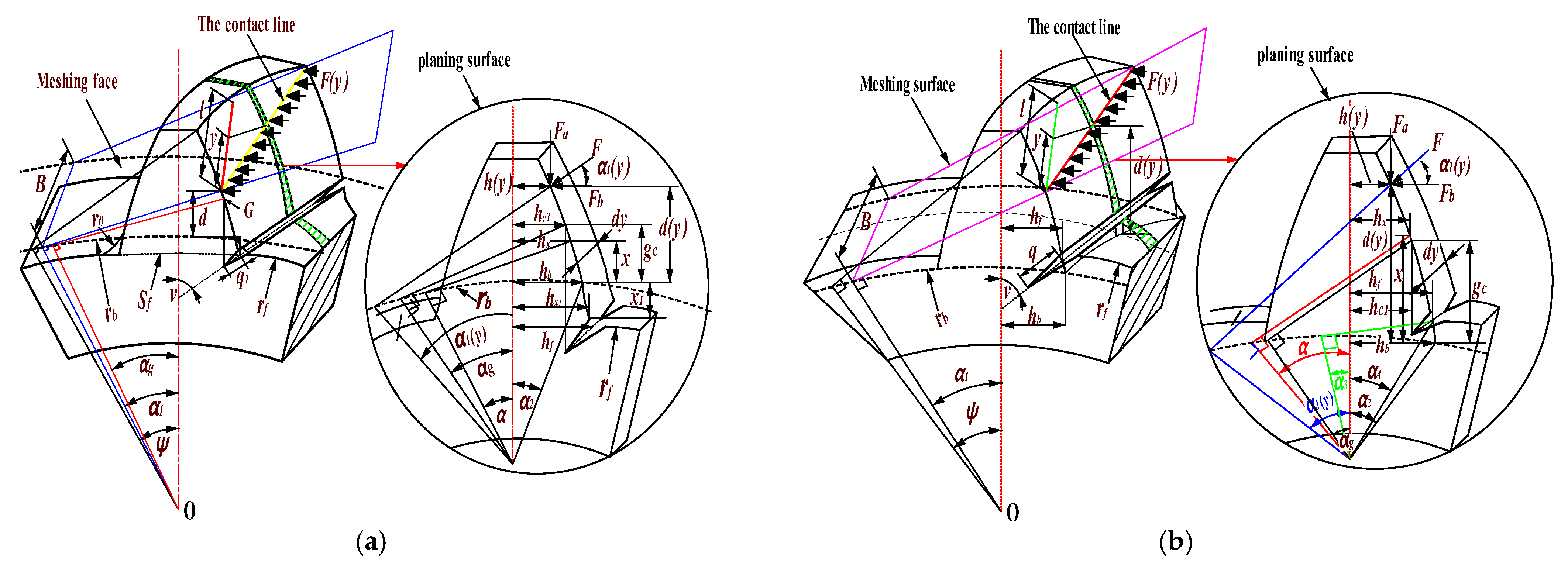
The tooth root crack is defined by the crack angle v (constant) and the crack depth q . Figure 4 shows a three-dimensional schematic of the cracked helical gear, as well as an enlarged view of the slice when considering the case where the tooth root circle is not equal to the base circle. In this paper, since the main study is on the response of the gear system when containing faults, the crack extension shape is assumed to be a parallelogram with the tangent length running through the entire tooth width, and the crack extension paths are linear and equal in depth along the direction of the dashed line in the figure, ignoring the effect of the crack thickness (degree of cracking) on the overall position of the gear tooth.
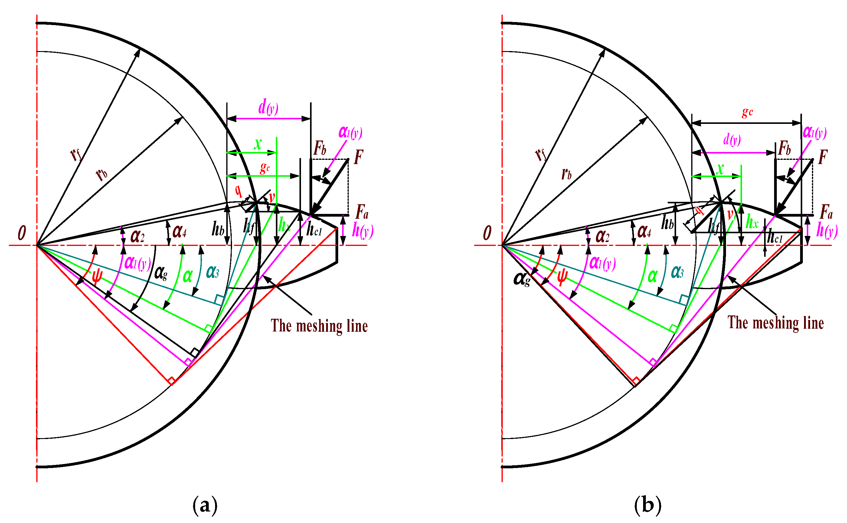
From Figure 4, it can be seen that when root crack damage occurs in the gear, the contact line length of the working teeth at the same meshing position does not change, so for the single tooth stiffness with root crack damage, the Hertzian contact stiffness does not change. For radial compression stiffness, the presence or absence of cracks does not affect the gear teeth to withstand radial loads, so the calculation of axial compression stiffness for the faulty gear teeth can also be derived according to the calculation method for normal gear teeth. Therefore, for the gear pair with root crack damage, it is only necessary to recalculate the bending stiffness and shear stiffness under the crack condition to indirectly obtain the integrated meshing stiffness with the gear pair with root crack damage. In this paper, the time-varying meshing stiffness of cracked helical gears can be calculated according to the following formula. The cracked helical gears are categorized into four cases, and the sliced cantilever beam models of their corresponding cracked spur gears are solved. Cases 1 and 2 are shown in Figure 5a,b; cases 3 and 4 are shown in Figure 6a,b.
(1)
As in the case of Figure 5a, r b > r f , h c 1 h r , and α 1 α g :
The inertia distance and cross-sectional area of the section of a cracked tooth at a distance x from the base circle are denoted as I x and A x , respectively, and their expressions are given below:
I x = 1 12 h c 1 + h x 3 B x g c I x = 1 12 2 h x 3 B   x > g c
A x = h c 1 + h x B x g c A x = 2 h x B   x > g c
where h c 1 is the perpendicular distance from the crack tip to the gear centerline, which is expressed as shown in Equation (19):
h c 1 = R b 1 sin α 2 q sin v
Based on the equations described in the previous section and the idea of the integral method, the bending and shear stiffnesses of the cracked gear teeth can be derived as:
K b c r a c k = j = 1 N 1 / 12 E α g α 2 1 + cos α 1 α 2 α sin α cos α 2 α 2 α cos α sin α 2 q 1 r b 1 sin ν + sin α + α 2 α cos α 3 Δ y d α + j = 1 N 1 / 1.5 E α 1 α g 1 + cos α 1 α 2 α sin α cos α 2 α 2 α cos α sin α + α 2 α cos α 3 Δ y d α + 0 r b r f 1.5 d y + x 1 cos α 1 h y sin α 1 2 2 E h x 1 3 d x 1
K s c r a c k = j = 1 N 1 / 1.2 E α g α 2 1 + ν α 2 α cos α cos 2 α 1 sin α 2 q 1 r b 1 sin ν + sin α + α 2 α cos α Δ y d α + j = 1 N 1 / 1.2 E α 1 α g 1 + cos α 1 α 2 α sin α cos α 2 α 2 α cos α sin α 2 q 1 r b 1 sin ν + sin α + α 2 α cos α Δ y d α + 0 r b r f 1.2 cos 2 α 1 G A x 1 d x 1
(2)
As in the case of Figure 5b, r b > r f and h c 1 < h r or h c 1 < h r and α 1 < α g :
Since x < g c is constant, the effective tooth thickness of the microelementary section at a distance x from the tooth root is constant h c 1 + h x , so I x and A x can be simplified by comparing with:
I x = 1 12 ( h c 1 + h x ) 3 B A x = ( h c 1 + h x ) B
The stiffness of each part can be expressed as:
K b c r a c k = j = 1 N 1 / 12 E α 1 α 2 1 + cos α 1 α 2 α sin α cos α 2 α 2 α cos α sin α 2 q 1 r b 1 sin ν + sin α + α 2 α cos α 3 Δ y d α + 0 r b r f 1.5 d y + x 1 cos α 1 h y sin α 1 2 2 E h x 1 3 d x 1
K s c r a c k = j = 1 N 1 / 1.2 E α 1 α 2 1 + ν α 2 α cos α cos 2 α 1 sin α 2 q 1 r b 1 sin ν + sin α + α 2 α cos α Δ y d α + 0 r b r f 1.2 cos 2 α 1 G A x 1 d x 1
(3)
As in the case of Figure 6a, r b < r f , h c 1 > h r , and α 1 < α g :
K b c r a c k = j = 1 N 1 / 12 E α g α 2 1 + cos α 1 α 2 α sin α cos α 2 α 2 α cos α sin α 2 q 1 r b 1 sin ν + sin α + α 2 α cos α 3 Δ y d α + j = 1 N 1 / 1.5 E α 1 α g 1 + cos α 1 α 2 α sin α cos α 2 α 2 α cos α sin α + α 2 α cos α 3 Δ y d α
K s c r a c k = j = 1 N 1 / 1.2 E α g α 2 1 + ν α 2 α cos α cos 2 α 1 sin α 2 q 1 r b 1 sin ν + sin α + α 2 α cos α Δ y d α + j = 1 N 1 / 1.2 E α 1 α g 1 + cos α 1 α 2 α sin α cos α 2 α 2 α cos α sin α 2 q 1 r b 1 sin ν + sin α + α 2 α cos α Δ y d α
(4)
As in the case of Figure 6b, r b < r f , h c 1 < h r or h c 1 > h r , and α 1 α g :
K b c r a c k = j = 1 N 1 / 12 E α 1 α 2 1 + cos α 1 α 2 α sin α cos α 2 α 2 α cos α sin α 2 q 1 r b 1 sin ν + sin α + α 2 α cos α 3 Δ y d α
K s c r a c k = j = 1 N 1 / 1.2 E α 1 α 2 1 + ν α 2 α cos α cos 2 α 1 sin α 2 q 1 r b 1 sin ν + sin α + α 2 α cos α Δ y d α
The integrated meshing stiffness of cracked gears can be solved by the following equation:
K t = 1 1 k h + 1 k b c r a c k + 1 k s c r a c k + 1 k a 1 + 1 k f 1 + 1 k b 2 + 1 k s 2 + 1 k a 2 + 1 k f 2
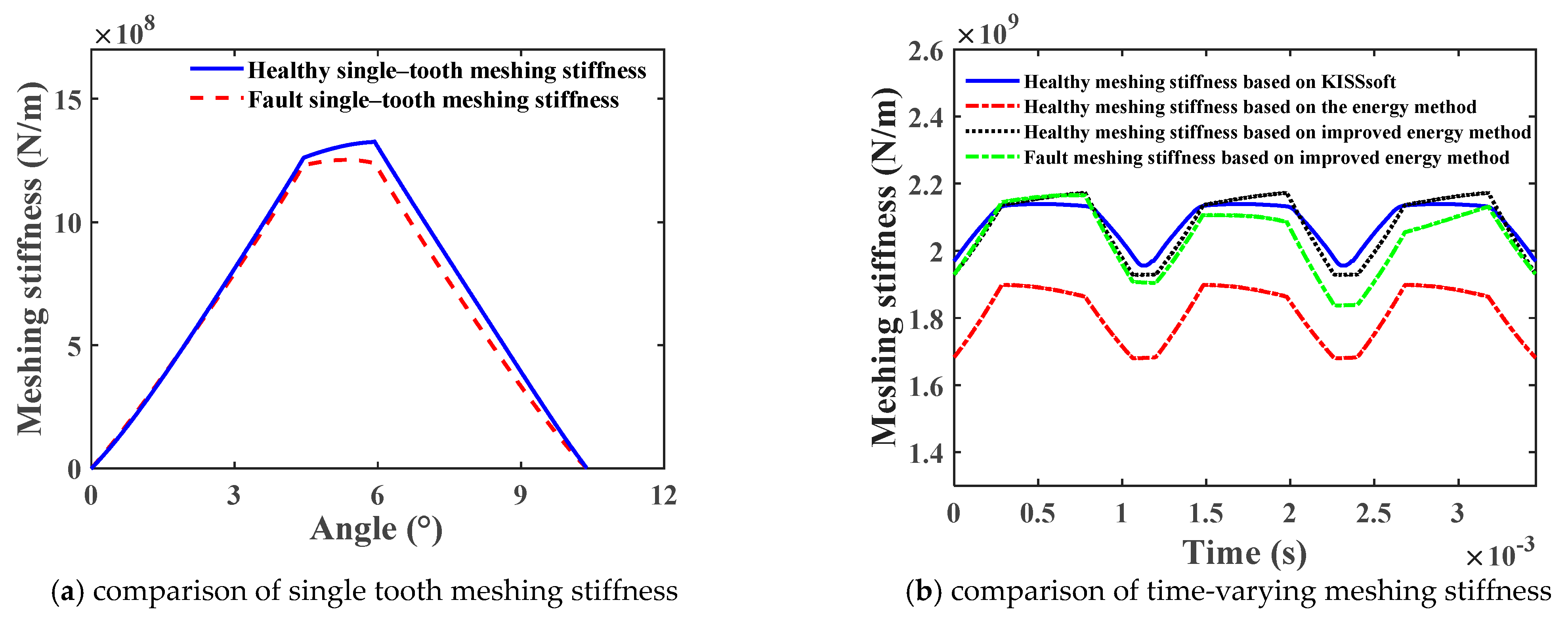
The crack depth is 5 mm, the crack angle is 45°, and the gear data are shown in Table 1. Based on MATLAB, the results of the traditional energy method, the improved energy method of this paper, and the KISSsoft simulation are compared. The comparison results are shown in Figure 7a, which is the comparison of single tooth meshing stiffness, and Figure 7b is the comparison of time-varying meshing stiffness.
It can be seen from Figure 7a,b that the presence of tooth root cracks causes localized attenuation of the meshing stiffness. The time-varying meshing stiffness of the faulty gear solved based on the improved energy method is very close to the meshing stiffness of the fault-free helical gear simulated based on the KISSsoft method. Compared with the simulation results of the unimproved meshing stiffness, the improvement effect is obvious. Therefore, it can be proved that the improved theoretical formula of time-varying meshing stiffness of fault helical gears is effective and realistic.

3. Dynamics Modeling of the Helical Gear-Rotor-Bearing Coupling System with Compound Faults

3.1. Dynamic Modeling of Helical Gear System

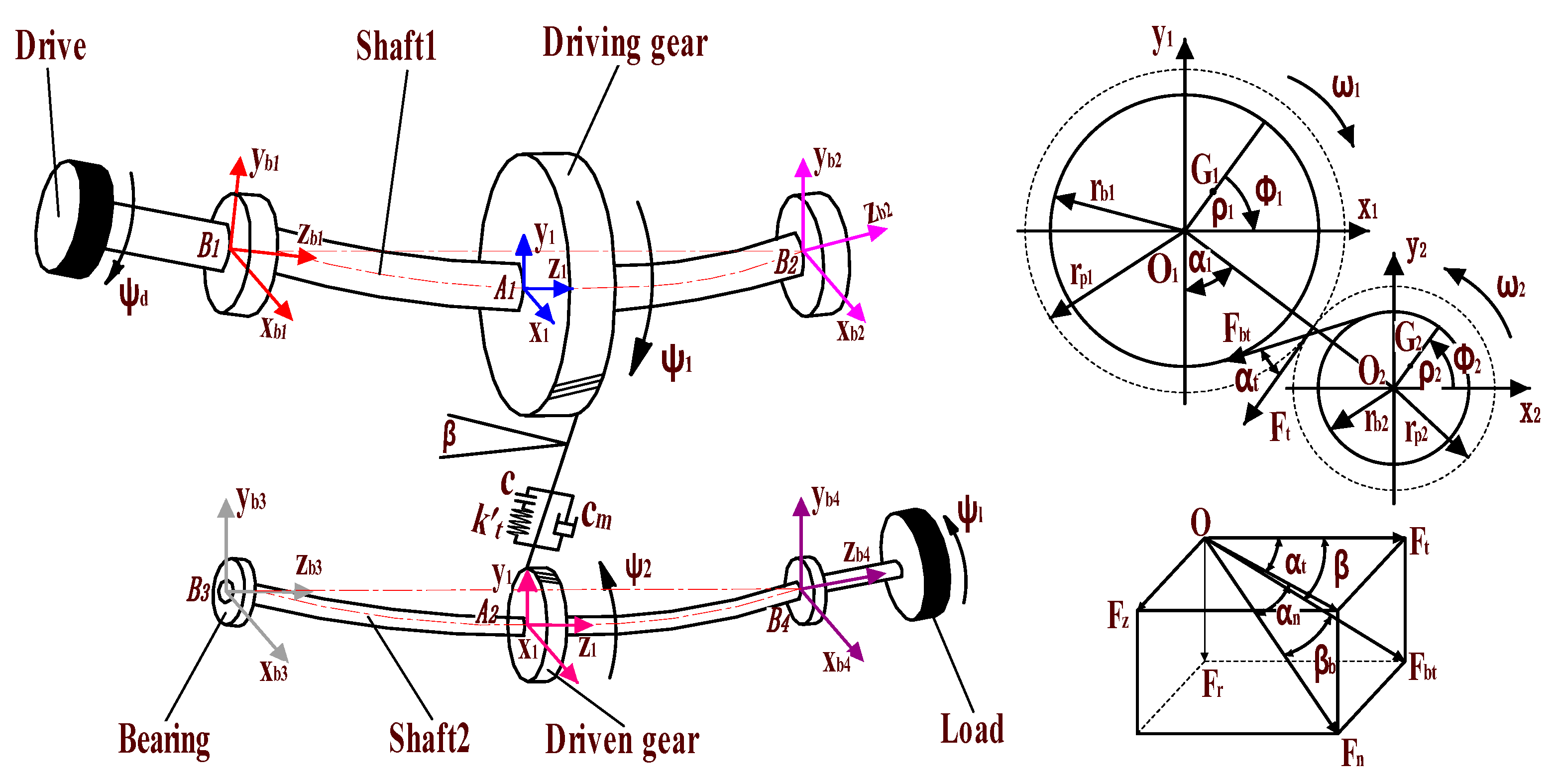
The dynamic model [29] diagram and geometrical position relationship of the faulty helical gear-rotor-bearing transmission system are shown in Figure 8.
As shown in Figure 8, the fixed coordinate system A i x i y i z i i = 1 , 2 is established in the ideal center A i of the driving and driven gears and the fixed coordinate system B i x i y i z i i = 1 4 is established in the ideal center B i of the bearing; the rotation center coordinates of the driving and driven gears are O 1 x 1 , y 1 , z 1 and O 2 x 2 , y 2 , z 2 , respectively; the center of mass coordinates are G 1 x g 1 , y g 1 , z g 1 and G 2 x g 2 , y g 2 , z g 2 ; the mass of helical gear is m 1 , m 2 ; the moment of inertia relative to the center of mass is J 1 , J 2 ; ρ 1 , ρ 2 are the eccentricity; r b 1 , r b 2 are the base circle radius; the equivalent mass at the bearing is m b i i = 1 4 ; the moment of inertia of the input device and the load are J d and J l , respectively; F t , F r , and F a are, respectively, the tangential force, radial force, and axial force when the gears are engaged; α t , α n are the end face pressure angle and normal phase pressure angle, respectively; β , β t are the spiral angles of the graduation circle and Base Circle, and α 1 is the angle between the center line of two gears and the vertical direction.
Based on the geometric relationship shown in Figure 8, the angular displacement of the input/output device, driving, and driven gears can be represented by Equation (30):
ψ d = ω 1 t + θ d ψ 1 = ω 1 t + θ 1 ψ 2 = ω 2 t + θ 2 ψ i = ω 2 t + θ l
In the formula, θ d , θ 1 , θ 2 , θ l are the torsional vibration angular displacement of the input device, the driving and driven gears, and the load, respectively. At t = 0 , the starting rotation angle of the driving and driven gears is 0, and the direction of rotation of the driving gears is positive. Then, the relationship between the center of mass G 1 , G 2 , and the center of rotation O 1 , O 2 , is shown in Equation (31) [29]:
x g 1 = x 1 + ρ 1 cos ( ψ 1 ) x g 2 = x 2 + ρ 2 cos ( ψ 2 )   z g 1 = z 1 z g 1 = z 1 y g 1 = y 1 + ρ 1 sin ( ψ 1 ) y g 2 = y 2 + ρ 2 sin ( ψ 2 )     z g 1 = z 1 z g 1 = z 1
where x i , y i , z i ( i = 1 2 ) are the horizontal, vertical, and axial vibrational displacements of the driving and driven gears, respectively. According to the geometric relationship, the dynamic deformation displacement of the helical gear pair in the meshing line direction can be expressed by Equation (32) [29]:
σ = r b 1 θ 1 r b 2 θ 2 + x 1 + ρ 1 cos ( ψ 1 ) x 2 + ρ 2 cos ( ψ 2 ) cos α 12 α t + y 1 ρ 1 sin ( ψ 1 ) y 2 + ρ 2 sin ( ψ 2 ) sin ( α 12 α t ) + z 1 z 2 tan ( β ) e ( t )
where e ( t ) = e 0 + e 1 cos ( ω e t ) is the integrated transmission error of the system, e 0 is the mean value of error, e 1 is the amplitude of error, and ω e = 2 π n 1 Z 1 / 60 is the meshing frequency. The meshing force of the gear meshing system along the meshing line direction can be expressed as F = c m d σ + k t f ( σ ) , k t is the faulty helical gear meshing stiffness when the crack depth q = 0 mm, it is the time-varying meshing stiffness for healthy helical gears. When ρ 1 = ρ 2 = 0 mm, the system does not contain gear eccentricity faults, while when it is not 0, the system has eccentricity faults. f x is the tooth side clearance function and can be expressed by Equation (33) [29];
f ( x ) = x b ( x > b ) 0 ( b x b ) x + b ( x < b )
The meshing force F between the gears is decomposed into the x-, y-, and z-directions, and the forces in each direction are shown in Equation (34) [29].
F x = F cos α 1 α t F y = F sin α 1 α t F z = F tan β

3.2. Vibration Analysis Model of Angular Contact Ball Bearings with Faults

A plane model of an angular contact ball bearing is shown in Figure 9. It is assumed that the outer ring of the bearing is fixed on the housing, and the inner ring is fixed on the rotating shaft. The rolling bodies are arranged at equal angular intervals between the inner/outer rings. The velocity v i , v o at the contact point between the rolling body and the inner/outer ring of the bearing is shown in Equation (35) [29]:
v i = ω i r i v o = ω o r o
where r i and r o are the radius of bearing inner/outer rings, respectively; ω i and ω o are angular speeds of bearing inner/outer rings, respectively. Assuming that the rolling body is purely rolling in the ideal state, then the rotational angular velocity of the cage and the rolling body are equal, and the linear velocity of the rolling body can be expressed as:
v b = v 0 + v i / 2 = ω 0 r o + ω i r i / 2
In general, the inner ring of the rolling bearing rotates with the rotating shaft, while the outer ring is bound with the bearing seat is not rotating, then there is ω i = 0 , ω 0 = ω . Therefore, the formula of the angular velocity ω b of the cage can be obtained as shown in (37):
ω b = 2 ν b / R + r = ω i r / R + r
Then, the rotation angle ω i of the i-th rolling body in time t is shown in Equation (38):
φ i = ω b t + 2 π ( i 1 ) / N b i = 1 , 2 , , N b
where N b is the number of bearing rollers:
In Figure 9, d b is the rolling body diameter of the bearing; d is the diameter of the axis; d i , d o are groove diameters of inner/outer rings of bearings, respectively; d m is the pitch diameter of the bearing, and d m = ( d i + d o ) / 2 ; D is the diameter of the bearing outer ring. The centrifugal force and gyroscopic moment generated by the rolling body are neglected in the bearing model because of the low rotational speed of the system studied in this paper. The deformation of the bearing at different positions is shown in Figure 10.
In Figure 10, A and A represent the distance between the centers of curvature of the grooves of the inner and outer rings of the bearing before and after loading, respectively; α 0 and α 0 are the contact angles before and after loading, respectively; P 0 and P 0 are the position of the bearing outer ring raceway curvature center before/after the force, respectively, because the bearing outer ring is fixed, the position of both are the same; P i and P i are the position of the center of curvature of the inner ring raceway of the bearing before/after the force, respectively; δ a i , δ r i , θ i are the radial deformation, axial deformation, and angular deformation caused by the force and torque, respectively; R i is the radius of the inner ring raceway curvature center track; δ i , δ 0 , and δ b i are the contact deformation and total deformation of the inner and outer channel of the ball bearing, respectively.
In Figure 10, the total deformation of the rolling body at position angle φ i can be expressed by the Equation (39):
δ b i = δ i + δ 0 h d = A A h d
where h d is the additional displacement caused by localized bearing failure, healthy roller bearings h d = 0 mm; rolling bearing localized damage is mainly manifested as spalling, cracks, and indentations on the surface of the outer ring, inner ring, or rolling element, and these failures are gradually formed by the early point damage at different stages of development. When the inner and outer rings or the rolling elements are damaged, the contact deformation between the rolling element and the inner ring and the outer ring will change. The mathematical expression of hd in the form of bearing inner ring, outer ring, and rolling element faults will be provided in Section 3.3 below.
According to the geometric relationship in Figure 10c, the distance A between the curvature center locus of the inner and outer ring channels after loading can be expressed as:
A = A sin α 0 + z + R i θ i cos φ i 2 + A cos α 0 + x cos φ i + y sin φ i 2 1 / 2
Then, the normal contact deformation δ b i of the i -th ball and raceway is shown in Equation (41):
δ b i = A A h d = A sin α 0 + δ a + R i θ i cos φ i 2 + A cos α 0 + δ r 2 1 2 A h d
Let δ a = z , δ r = x cos φ i + y sin φ i δ a = z , then Equation (41) can be reduced to:
δ b i = A A h d = A sin α 0 + z + R i θ i cos φ i 2 + A cos α 0 + x cos φ i + y sin φ i 2 1 2 A h d
where x, y, and z are vibration displacements along x-, y- and z-directions, respectively; R i is the radius of the locus of curvature center of the inner ring channel, A is the distance between the initial inner and outer ring channel curvature centers A = r i + r o + γ o d b .
According to the geometric relation, the actual contact angle of the ball is α 0 at the position Angle φ i (the contact Angle of the inner and outer rings is equal).
tan α 0 = A sin α 0 + z + R i θ i cos φ i / A cos α 0 + x cos φ i + y sin φ i
According to Hertz’s contact theory, the contact pressure generated by the i -th ball and raceway is f b i . It is considered that only normal positive pressure can be generated between the ball bearing and the raceway, so there is a force when the δ b i > 0 , as shown in Equation (44):
f b i = K c δ b i 3 / 2 H δ b i
Equation (44) is the normal load acting on the trench along the contact angle direction, where K c is the Hertzian contact stiffness; H x is the Heaviside function, and the axial and radial components of this load decomposition can be expressed by Equation (45):
f r i = f b i cos α 0 = K c δ b i 3 / 2 H δ b i cos α 0 f a i = f b i sin α 0 = K c δ b i 3 / 2 H δ b i sin α 0
The components F b x , F b y , and F b z of bearing force generated by angular contact bearing in x-, y-, and z-directions are, respectively:
F b x = i = 1 N b f r i cos φ i = i = 1 N b = K c δ b i 3 / 2 cos α 0 H δ b i cos φ i F b y = i = 1 N b f r i sin φ i = i = 1 N b = K c δ b i 3 2 cos α 0 H δ b i sin φ i F b z = i = 1 N b f a i = i = 1 N b = K c δ b i 3 / 2 sin α 0 H δ b i

3.3. Establishment of Bearing Excitation Model with Typical Faults

In order to simulate the faults of the inner ring, outer ring, and rolling element of rolling bearings, the following will provide their mathematical expressions and solve their corresponding solutions for each fault form.
(1) Fault model of bearing inner and outer rings
As shown in Figure 11, assuming that the shape of the local fault on the bearing surface is a circular pit, the diameter and depth of the inner and outer ring fault areas are represented by L di , L do and h di , h do , respectively; Δ h di and Δ h do are the actual depths at which the rolling element of the bearing falls into the inner and outer rings of the bearing, respectively; θ i e and θ o e are half of the center angles corresponding to the inner and outer fault areas, respectively; θ i d and θ o d represent the rotation angles of the center of the damaged area in the inner and outer rings, respectively; R b 1 is the radius of the rolling element.
When the rolling element is in the fault position of the outer ring, due to the binding angular velocity between the outer ring and the bearing seat being 0, the position angle θ o d of the fault center of the outer ring is a constant, and displacement excitation only exists when the rolling element is in the fault zone. Therefore, the additional displacement caused by local failure of the bearing outer ring can be expressed as:
h d = Δ h d o a b s mod φ i θ od , 2 π θ oe 0 other
The parameters in Equation (47) can be represented by Equations (48) and (49).
θ oe = arcsin L d o r o
Δ h d o = r o r o 2 L d o 2 2
Similarly, when the rolling element is in an inner ring fault, due to the movement of the bearing inner ring with the shaft, the position angle θ i d of the inner circle fault center is time-varying, which can be expressed as: θ i d t = θ i d 0 + ω 1 t . Therefore, the additional displacement caused by local failure of the bearing inner ring can be expressed as:
h d = Δ h d i a b s mod φ i θ i d t , 2 π θ ie 0 other
The calculation method for the parameters in Equation (50) is similar to that of the outer ring fault parameters and will not be given in this article.
(2) Fault model of bearing rolling element
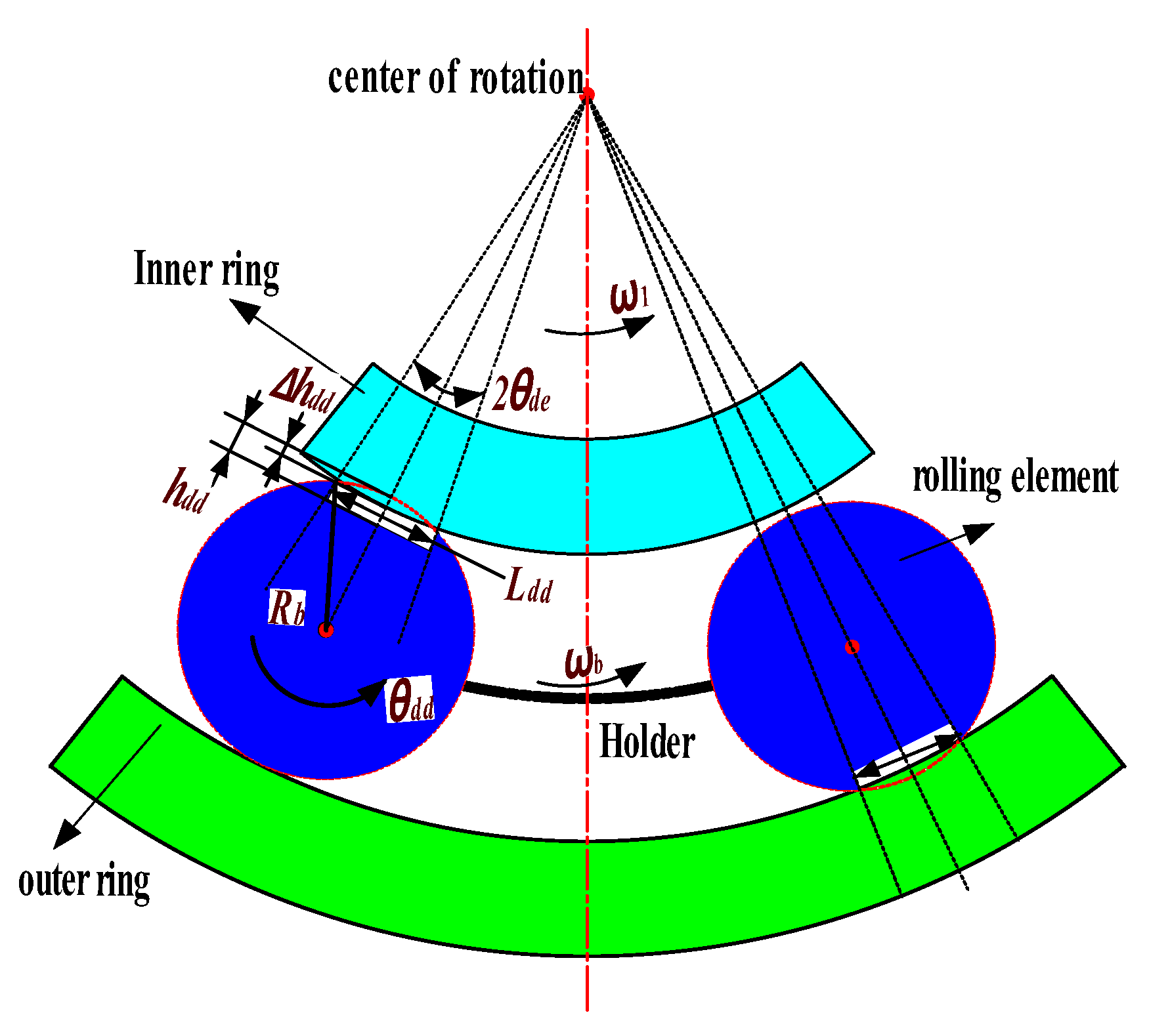
For the rolling element of the bearing, its rotation will contact the inner and outer rings of the bearing once, which will generate displacement excitation and cause impact vibration of the system. In order to simulate the failure of the rolling element, it is assumed that the rolling element is damaged by pits. When a failure occurs, the radial clearance of the bearing will suddenly change. The schematic diagram of the rolling element failure is shown in Figure 12. The diameter and depth of the fault area of the rolling element are represented by L d d and h d d , respectively; Δ h d d is the actual depth at which the bearing rolling element falls into the inner and outer rings of the bearing, and θ d d is the angle at which the centerline of the fault area rotates during the rolling element’s rotation.
Assuming that the j -th rolling element fails, its damage angle position at time t is:
θ d d = ω s t + 2 π ( j 1 ) N b
where ω s is the rotational speed of the rolling element, which can be represented by Equation (52):
ω s = ω 2 d m D b 1 D b d m cos α 2
Assuming the position angle θ 0 of the centerline of the initial position of the rolling element is when the fault position of the first rolling element contacts the inner and outer rings at time t , the additional displacement caused by local failure of the bearing rolling element can be expressed as:
h d = Δ h d d a b s mod θ d d , 2 π θ 0 θ d e Δ h d d a b s mod θ d d , 2 π π θ 0 θ d e 0 other
The calculation method for the parameters in Equation (53) is similar to that of the outer ring fault parameters and will not be given in this article.

3.4. Compound Fault Helical Gear-Rotor-Bearing Coupling Dynamic Equation

It is considered that the helical gear-rotor-bearing system consists of gears, bearings, transmission, and load devices. Based on the dynamics analysis of the system, the kinetic, potential, and dissipation functions of the system are established and substituted into the Lagrange equation; the differential equations of the system can be expressed as in Equations (54)–(60).
The control differential equations for the input device and the left end bearing of the drive shaft can be expressed by Equations (54) and (55):
J d θ ¨ d + c t 1 θ ˙ d θ ˙ 1 + k t 1 θ d θ 1 = T d
m b 1 x ¨ b 1 + c s x 1 x ˙ b 1 x ˙ 1 + k s x 1 x b 1 x 1 + c b 1 x ˙ b 1 = F b x 1 m b 1 y ¨ b 1 + c s y 1 y ˙ b 1 y ˙ 1 + k s y 1 y b 1 y 1 + c b 1 y ˙ b 1 = F b y 1 m b 1 g m b 1 z ¨ b 1 + c s z 1 z ˙ b 1 z ˙ 1 + k s z 1 z b 1 z 1 + c b 1 z ˙ b 1 = F b z 1
The control differential equation of the driving gear is shown in Equation (56):
m 1 x ¨ 1 + c s x 1 x ˙ 1 x ˙ b 1 + c s x 2 x ˙ 1 x ˙ b 2 + k s x 1 x 1 x b 1 + k s x 2 x 1 x b 2 = F x + m 1 ρ 1 θ ¨ 1 sin φ 1 + m 1 ρ 1 ω 1 + θ ˙ 1 2 cos φ 1 m 1 y ¨ 1 + c s y 1 y ˙ 1 y ˙ b 1 + c s y 2 y ˙ 1 y ˙ b 2 + k s y 1 y 1 y b 1 + k s y 2 y 1 y b 2 = m 1 g F y + m 1 ρ 1 θ ¨ 1 cos φ 1 + m 1 ρ 1 ω 1 + θ ˙ 1 2 sin φ 1 m 1 z ¨ 1 + c s z 1 z ˙ 1 z ˙ b 1 + c s z 2 z ˙ 1 z ˙ b 2 + k s z 1 z 1 z b 1 + k s z 2 z 1 z b 2 = F z J 1 + m 1 ρ 1 2 θ ¨ 1 + c t 1 θ ˙ 1 θ ˙ d + k t 1 θ 1 θ d = m 1 ρ 1 x ¨ 1 sin φ 1 + m 1 ρ 1 y ¨ 1 cos φ 1 F r b 1
The control differential equations of the right bearing of the drive shaft and the left bearing of the driven shaft are given in Equation (57):
m b 2 x ¨ b 2 + c s x 2 x ˙ b 2 x ˙ 1 + k s x 2 x b 2 x 1 + c b 2 x ˙ b 2 = F b x 2 m b 2 y ¨ b 2 + c s y 2 y ˙ b 2 y ˙ 1 + k s y 2 y b 2 y 1 + c b 2 y ˙ b 2 = F b y 2 m b 2 g m b 2 z ¨ b 2 + c s z 2 z ˙ b 2 z ˙ 1 + k s z 2 z b 2 z 1 + c b 2 z ˙ b 2 = F b z 2 m b 3 x ¨ b 3 + c s x 3 x ˙ b 3 x ˙ 2 + k s x 3 x b 3 x 2 + c b 3 x ˙ b 3 = F b x 3 m b 3 y ¨ b 3 + c s y 3 y ˙ b 3 y ˙ 2 + k s y 2 y b 3 y 2 + c b 3 y ˙ b 3 = F b y 3 m b 3 g m b 3 z ¨ b 3 + c s z 3 z ˙ b 3 z ˙ 2 + k s z 3 z b 3 z 2 + c b 3 z ˙ b 3 = F b z 3
The control differential equation of the driven gear is shown in Equation (58):
m 2 x ¨ 2 + c s x 3 x ˙ 2 x ˙ b 3 + c s x 4 x ˙ 2 x ˙ b 4 + k s x 3 x 2 x b 3 + k s x 4 x 2 x b 4 = F x + m 2 ρ 2 θ ¨ 2 sin φ 2 + m 2 ρ 2 ω 2 + θ ˙ 2 2 cos φ 2 m 2 y ¨ 2 + c s y 3 y ˙ 2 y ˙ b 3 + c s y 4 y ˙ 2 y ˙ b 4 + k s y 3 y 2 y b 3 + k s y 4 y 2 y b 4 = m 2 g F y + m 2 ρ 2 θ ¨ 2 cos φ 2 + m 2 ρ 2 ω 2 + θ ˙ 2 2 sin φ 2 m 2 z ¨ 2 + c s z 3 z ˙ 2 z ˙ b 3 + c s z 3 z ˙ 2 z ˙ b 4 + k s z 3 z 2 z b 3 + k s z 4 z 2 z b 4 = F z J 2 + m 2 ρ 2 2 θ ¨ 2 + c t 2 θ ˙ 2 θ ˙ l + k t 2 θ 2 θ l = m 2 ρ 2 x ¨ 2 sin φ 2 + m 2 ρ 2 y ¨ 2 cos φ 2 F r b 2
The control differential equations for the left end bearing of the driven shaft and the load device can be expressed in Equations (59) and (60):
m b 4 x ¨ b 4 + c s x 4 x ˙ b 4 x ˙ 2 + k s x 4 x b 4 x 2 + c b 4 x ˙ b 4 = F b x 4 m b 4 y ¨ b 4 + c s y 4 y ˙ b 4 y ˙ 2 + k s y 4 y b 4 y 2 + c b 4 y ˙ b 4 = F b y 4 m b 4 g m b 2 z ¨ b 4 + c s z 4 z ˙ b 4 z ˙ 2 + k s z 4 z b 4 z 2 + c b 4 z ˙ b 4 = F b z 4
J l θ ¨ l + c t 2 θ ˙ l θ ˙ 2 + k t 2 θ l θ 2 = T l
The representative meanings of each parameter in the above equation and the bearing parameters are shown in reference [29], the remaining parameters of the gear are shown in Table 2, and the parameters of the shaft are shown in Table 3.

4. Analysis of Vibration Characteristics of Helical Gear-Rotor-Bearing System with Faults

4.1. Analysis of Vibration Characteristics of Health Systems

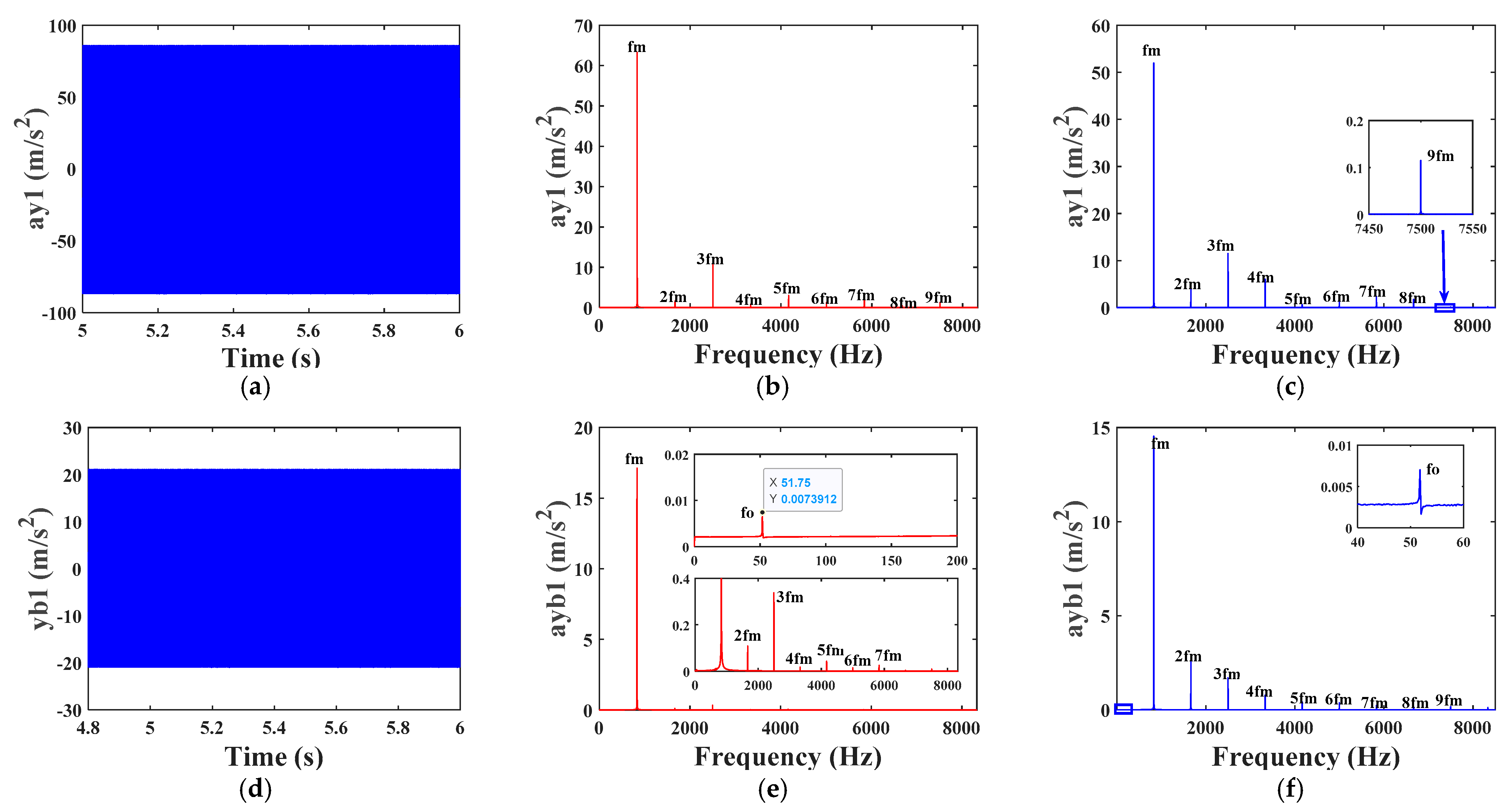
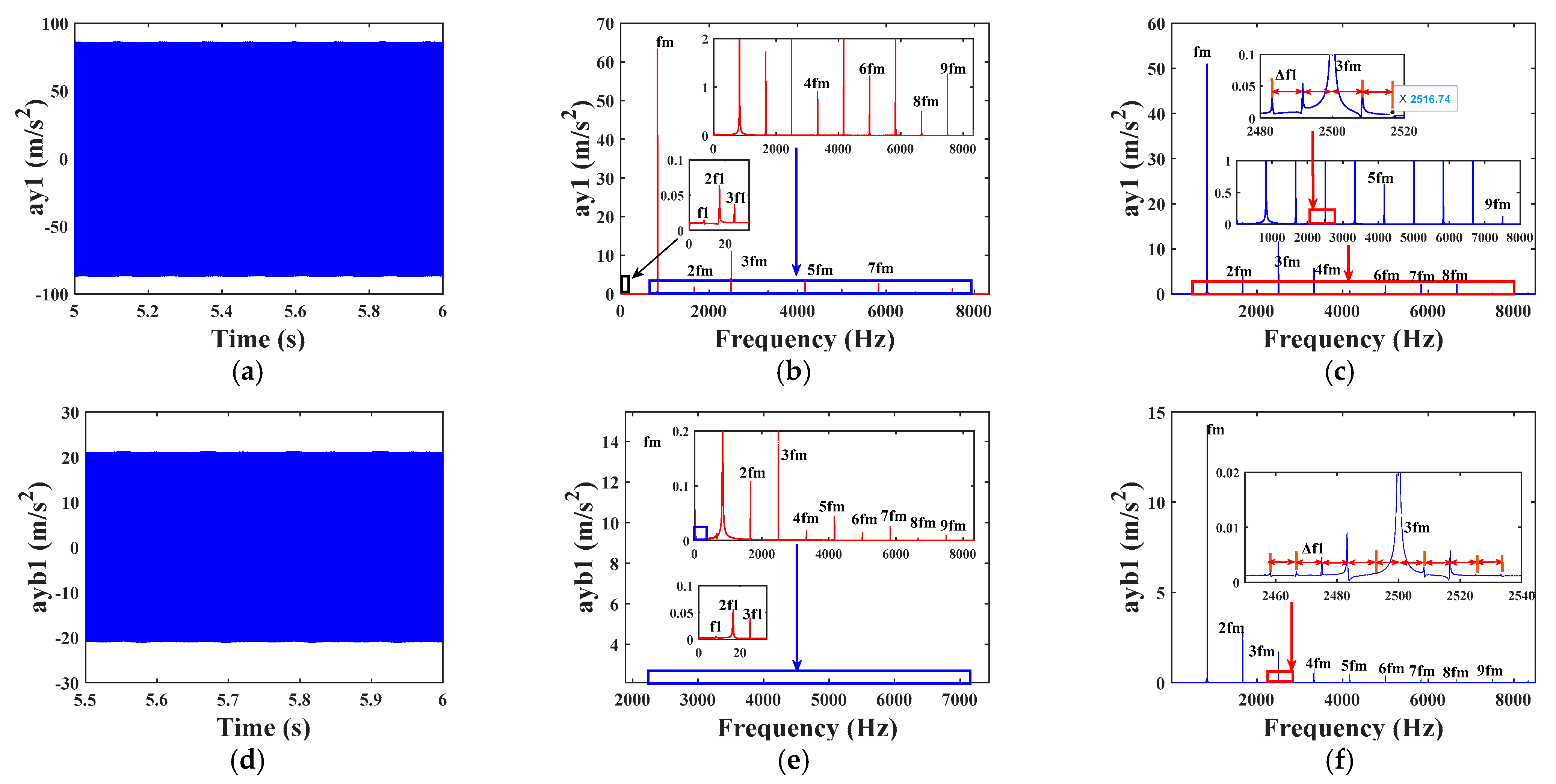
Based on the differential equations of the helical gear-rotor-bearing drive system established in Section 3.4 of this paper, Matlab was used to program it, and the ode15s command was used to solve the response of the system for the parameters in Table 1, Table 2 and Table 3. Calculate the acceleration response during vibration of the fault-free system at input speed n 1 = 500 r/min, eccentricity of the driving and driven gears ρ 1 = ρ 2 = 0 mm, root crack depth q = 0 mm, and additional displacement due to localized bearing failure h d = 0 mm (This is mainly to provide a comparison to the later vibration characterization of the fault-containing system). Figure 13a,d shows the time-domain waveform of the driving gear and corresponding left end bearing in the y-direction, Figure 13b,e shows the spectrum in the corresponding direction, and Figure 13c,f shows the envelope spectrum. In the figure, y 1 represents the y-direction of the driving gear and y b 1 represents the y-direction of the left end bearing of the driving gear (the same expression will be used later).
From Figure 13a,d, it can be seen that with the periodic rotation of the gears, the time-domain curves of y-direction acceleration of both the driving gear and the bearings change periodically, and the amplitude of vibration remains smooth and constant. From the frequency spectrum and envelope spectrum of the driving gear in the y-direction in Figure 13b,c, it can be seen that its frequency mainly includes the meshing frequency f m and its octave frequency ( 2 f m , 3 f m ,… n f m ) of the gear, in which the meshing frequency f m shows the strongest as the dominant frequency; from the frequency spectrum of the bearing and the envelope spectrum of Figure 13e,f, it can be seen that, due to coupling, the gear meshing frequency and octave frequency also appear in the y-direction of the bearing, but the frequency component is weaker than that in the gear direction, in addition to this, a weaker bearing dynamic stiffness frequency f 3 (52 Hz) also appears, as can be seen from the localized zoomed-in diagram (40–60 Hz).
In summary, the time-domain waveforms of the gears and bearings in the fault-free helical gear-rotor-bearing system exhibit periodic vibration in all directions with vibration amplitude is smooth, and the frequency components are mainly composed of the meshing frequency f m and its octave frequency n f m , and f m is the dominant frequency.

4.2. Analysis of Vibration Response and Parameter Effects of a Single Fault System with Gear Eccentricity

4.2.1. Analysis of Vibration Characteristics of a Single Fault System with Eccentricity

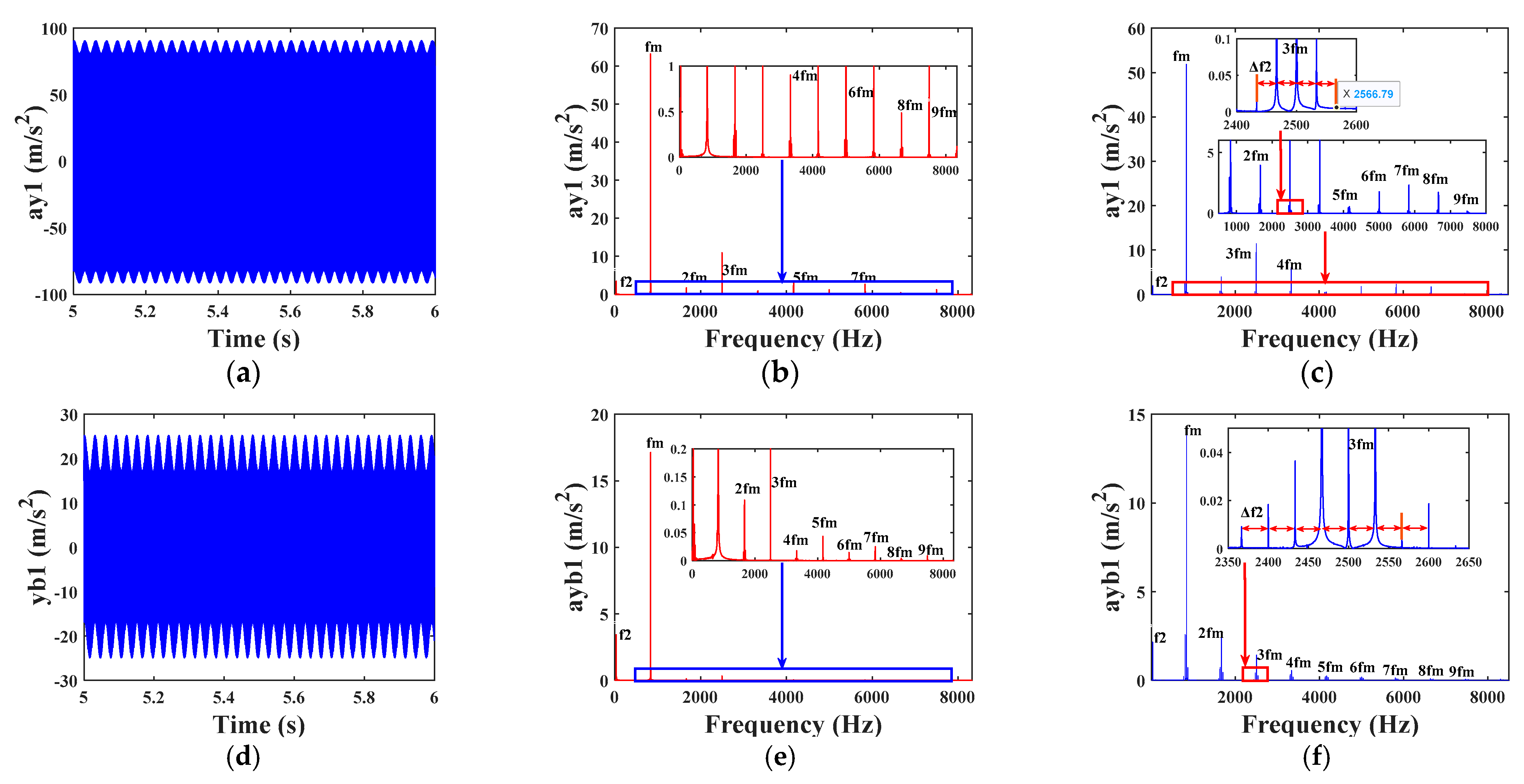
The existence of gear eccentricity will lead to gear transmission instability, resulting in the system vibration response to produce fault characteristics; first of all, on the basis of Section 4.1 in the text, respectively, take the gear eccentricity as ρ 1 = 0 mm, ρ 2 = 0.15 mm, and ρ 1 = 0.15 mm, ρ 2 = 0 mm, respectively, to calculate the driving/driven gear containing eccentricity fault state of the Helical gear-rotor-bearing dynamic response; the results are shown in Figure 14 and Figure 15, respectively. Figure 14a,d shows the vibration time-domain response of the driven gear containing eccentricity, Figure 14b,e shows the corresponding spectra, and Figure 14c,f shows the corresponding envelope spectra; Figure 15 shows the simulation results when there is an eccentricity fault in the driving gear, and the expression of the meaning of each figure is the same as that of Figure 14.
From Figure 14a,d, it can be seen that compared with Figure 13a,d, when there is an eccentricity fault in the driven gear, the time-domain waveforms at the y-direction of the gear and the bearing show a shock vibration in the shape of a periodic ripple, and the amplitude of the vibration increases significantly. From the envelope spectra of the gears and bearings in Figure 14c,f, it can be seen that relative to the vibration response of the healthy system, the mesh frequency of the gears and bearings in the y-direction of the system containing the eccentricity fault and its octave on both sides of the system form a side frequency band, the interval of which is the rotational frequency of the faulty gear (the driven gear) Δ f 2 = f 2 = n 2 /60 (33.3 Hz). It can be seen that the main frequencies of the system containing the eccentricity of the driven gear are mainly composed of f 2 , n f m , n f m ± m f 2 ( m , n = 1, 2, 3…).
From Figure 15a,d, it can be seen that the faults acting on the active gear show obvious differences compared to the driven wheel, and the vibration time domain response of the active gear (large gear) containing eccentricity faults remains almost the same as that of the normal gear vibration signals, and the amplitude of the vibration remains basically unchanged. It appears that the effect of the same eccentricity fault parameter on the vibration response of the active wheel is weaker than that of the driven gear, which is due to the fact that the diameter of the active gear is much larger than that of the driven gear, and the change of the center of mass position due to the eccentricity fault is relatively small. From the corresponding envelope spectrum in Figure 15c,f, it can be seen that due to the eccentricity fault acting on the active gear, its side frequency is the active gear shaft rotation frequency Δ f 1 = f 1 = n 1 /60 (8.3 Hz), which is relatively weaker than Figure 14c,f, and its component of the fault eigenfrequency is relatively weaker. It can be seen that the main frequencies of the system containing active gear eccentricity are mainly composed of f 1 , n f m , n f m ± m f 1 ( m , n = 1, 2, 3…).
It can be seen from the previous analysis that the vibration response of the system is more sensitive to the eccentric fault of the pinion (driven gear). In order to study the influence of the eccentric fault on the response of the gear system, this section takes the driven gear with eccentric fault as the research object and takes the eccentric distance ρ 1 = 0 mm, ρ 2 takes 0 mm, 0.06 mm, 0.12 mm, and 0.18 mm to obtain the response of the system at different eccentric distances, respectively. The response of the system at different eccentricity distances is obtained. In this paper, the difference between the vibration acceleration value in the fault state and the vibration acceleration value in the normal state is defined as the residual signal denoted by A c c , which reduces the interference of the transmission error on the crack fault characteristics, and the time domain and envelope spectra of the residual of the gear vibration acceleration with different eccentricities are shown in Figure 16.
From Figure 16a,c, it can be seen that with the increase of the eccentricity of the driven gear, the residual amplitude of the time-domain response of the gears and bearings is larger, and the vibration is more intense; from Figure 16b,d, the comparison of the residual envelope spectra, it can be clearly seen that, with the increase of the eccentricity of the gears and bearings, the amplitude of the main frequencies f 2 , f m and n f m increase, while the mesh frequency and its harmonic frequency on both sides of the amplitude of the sideband frequency of the mesh frequency and its harmonics. The amplitude of the sideband frequencies also increases, and the fault characteristics become more obvious.
The gear eccentricity fault has an important and significant impact on the time-domain and frequency-domain response of the system’s vibration. In order to more sensitively reflect the impact of eccentricity fault degree on the system’s vibration response, statistical analysis of eccentricity faults is needed. Statistical index analysis of the time-domain signals of the system under different eccentricity fault parameter states can be used to evaluate the degree of eccentricity faults. Take the eccentricity fault of the driven gear from 0.01 mm to 0.36 mm, take a value every 0.02 mm, and solve it. Calculate the kurtosis and root mean square of the time-domain vibration signal of the gear to evaluate the degree of eccentricity fault. The calculation process of the above statistical indexes has been described in the literature [30] and will not be expanded in detail here.
In order to compare the impact of eccentricity on fault characteristics, this article uses the statistical index percentage method for calculation, and the calculation formula is shown in Equation (61).
X i = X i f X i h X i h × 100 %
In the Equation (61), the subscript f represents the value of the statistical index of the fault signal, h represents the value of the statistical index of the health signal, X i ( i = 1, 2) represents the root mean square value and kurtosis of statistical feature quantities, respectively. In order to visibly observe the statistical results, the calculated X i is normalized, and the processed X i is denoted as X i 1 , as shown in Equation (62):
X i 1 = X i X i m i n X i m a x X i m i n
where X i max and X i min are the maximum and minimum values in X i with different eccentricity, respectively.
The comparison of the sensitivity of different statistical indicators to the degree of eccentricity is shown in Figure 17.
The trends of normalized and non-normalized crag and rms data are compared, respectively, and the results are shown in Figure 17a,b. Figure 17a shows the trend of the statistical characteristics of the original simulated signal, and Figure 17b shows the trend of the signal with the increase of the eccentricity of the driven gear in the normalized case. As can be seen from Figure 17a, the two indicators have the same trend; both gradually increase with the increase of eccentricity level, and when ρ 2 < 0.06 mm when the curve of the growth trend is weak, the indicator is almost 0; in this range, the eccentricity of the system’s impact on the system can be negligible; and when ρ 2 > 0.06 mm when the un-normalized and normalized statistical indicators of the trend of the sharp increase (the craggy performance is more pronounced). It can be seen that as the eccentricity continues to increase, the crag and the root mean square are more sensitive; when the eccentricity is in the lower range, the vibration amplitude of the system increases slowly, and when it reaches a certain value, it will lead to a significant increase in the vibration amplitude of the system. In real life, the existence of gear eccentricity cannot be avoided, but should minimize the installation error. To avoid the installation of gears, there is a large amount of eccentricity resulting in increased vibration of the system.

4.2.2. Analysis of Vibration Characteristics of a Single Fault System with Root Cracks

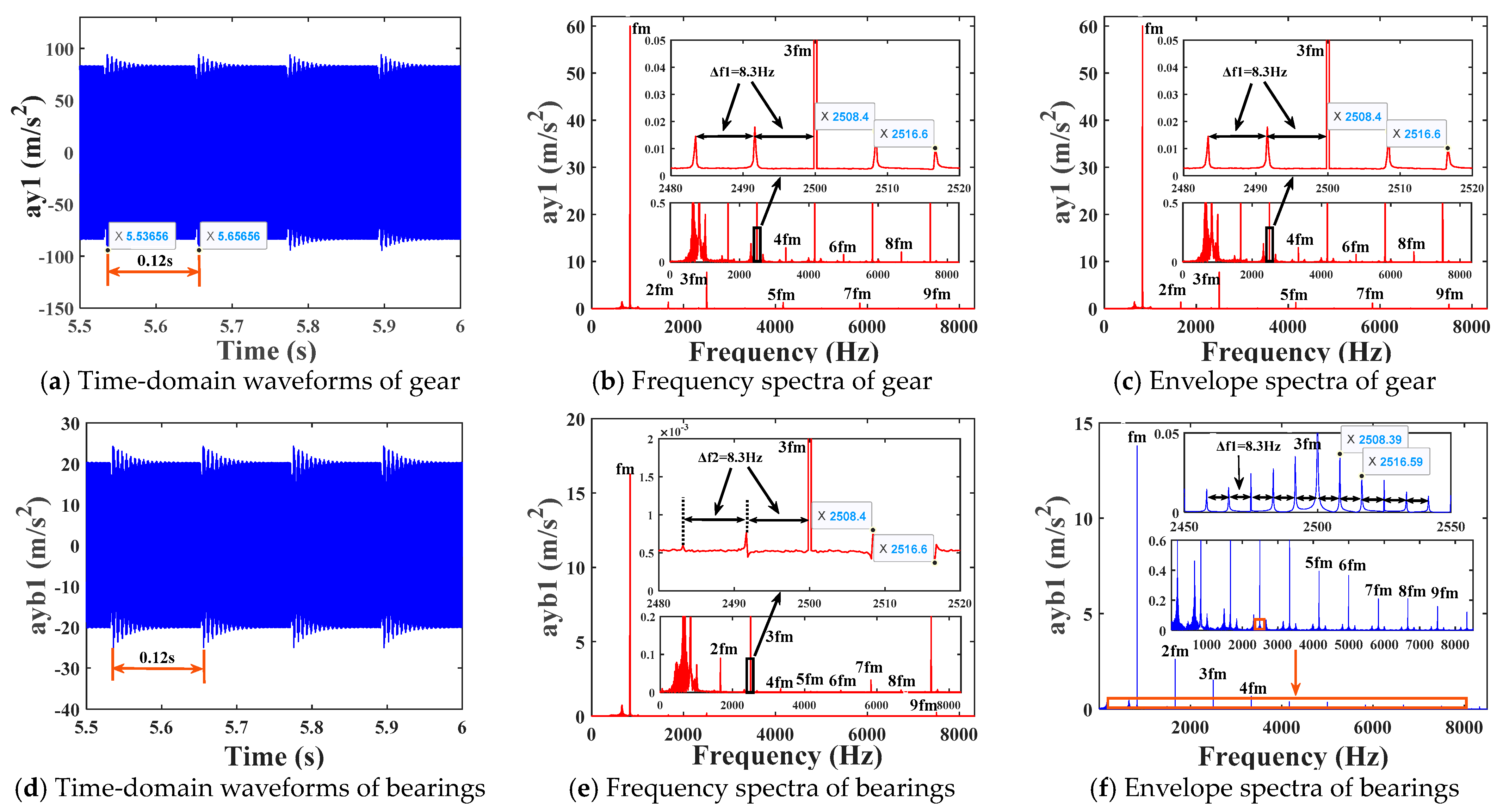
Taking the input speed n 1 = 500 r/min; eccentricity ρ 1 = ρ 2 = 0 mm; H b = 0 mm; gear crack depth q = 12.5 mm, crack angle v = 45°; solve the vibration response of the helical gear-rotor-bearing rotating system with a single fault containing tooth root crack; the simulation results are shown in Figure 18 (the frequency domain diagram contains the local amplification of part of the frequency band). The representations of each figure and the parameters in the figures are the same as in Section 4.2.1.
From Figure 13a,c, it can be seen that compared with Figure 18a,d, the time domain waveforms in the y-direction of the gears and bearings have undergone obvious changes, and the time domain response curves of the crack-containing faults, in addition to the mesh impacts of the normal gears, also produce more obvious mutation impact response when the cracked gear teeth are involved in the mesh, and the interval between the two neighboring bilateral peaks of the impacts is a rotational period of the faulty gears T = 0.12 s. This is consistent with the decay period interval between two adjacent stiffnesses of a faulty helical gear with time-varying meshing stiffness. It can be seen that the time-varying meshing stiffness has a greater impact on the results of the system response, and the tooth root crack damage characteristics on the vibration signal form were also obtained. As can be seen from the spectrogram Figure 18b,e, envelope spectrum Figure 18c,f, and local magnification of the y-direction of the gears and bearings, the active gears and the corresponding bearings spectrograms and envelope spectra show a modulated side-frequency band centered on the gear meshing frequency f m and the octave frequency n f m , with the side-frequency intervals equal to the rotational frequency of the faulty gears, Δ f 1 = 8.3 Hz, which can be used to diagnose the cracked root of the gears in the system. In summary, the frequency of systems with single root crack faults is mainly composed of Δ f 1 , n f m ± m f 1 ( m , n = 1, 2, 3…).
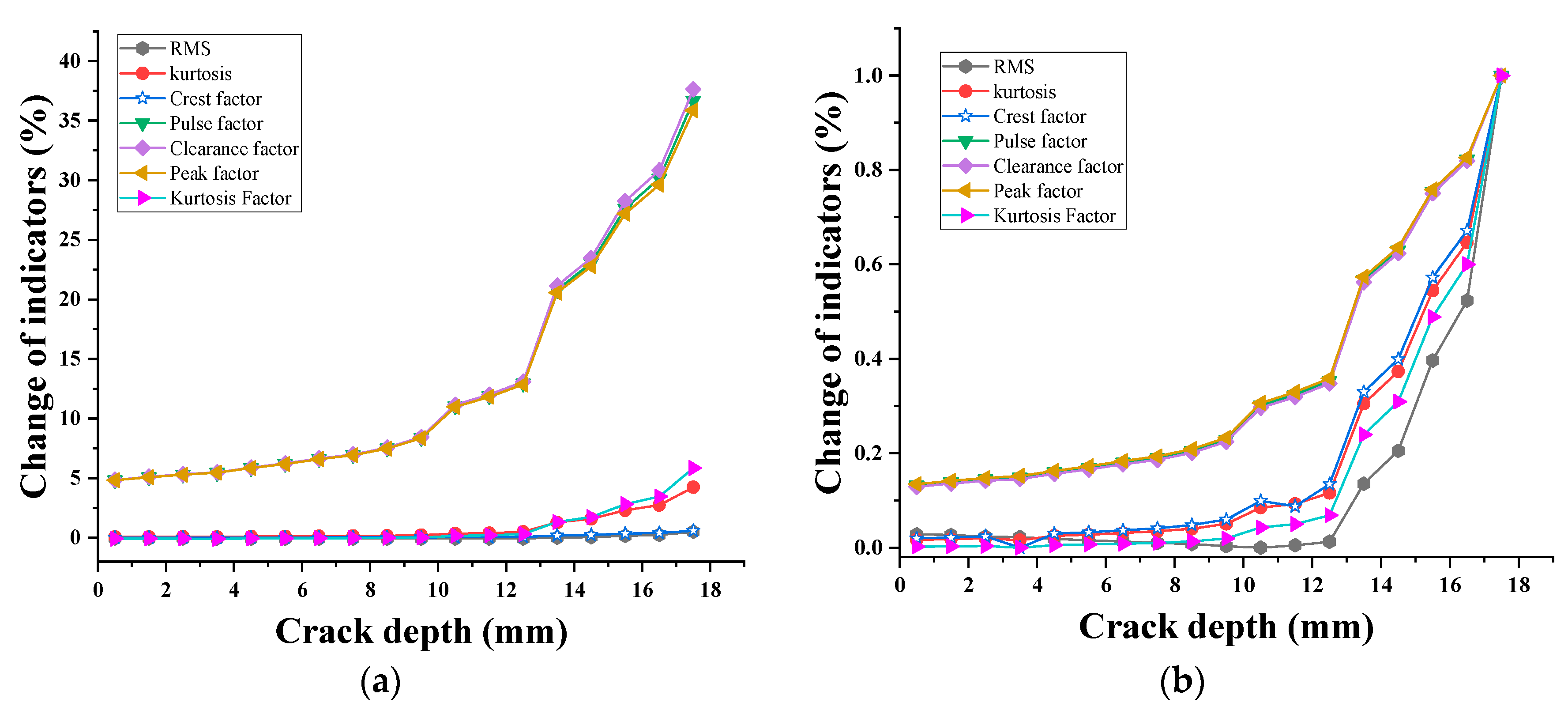
To investigate the impact of root crack failure on system response, crack depths of 0 mm, 0.5 mm, 1.5 mm, 2.5 mm…, and 17.5 mm are taken as different crack levels. The root mean square, kurtosis, kurtosis factor, shape factor, pulse factor, margin factor, and peak factor of the system vibration time-domain waveform are calculated for different crack depths to evaluate the degree of crack failure; the results are shown in Figure 19a,b.
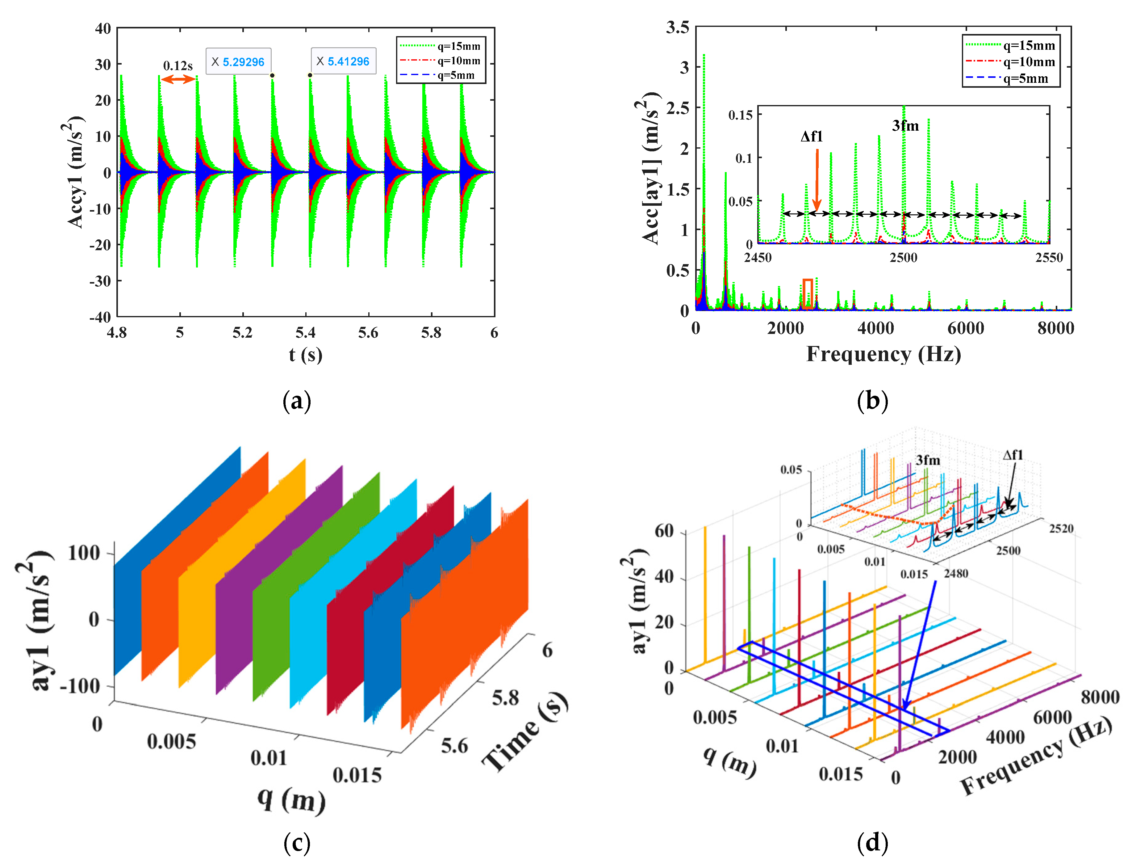
In order to investigate the impact of crack depth q on the vibration response of the system, this section takes crack depths of 0 mm, 5 mm, 10 mm, and 15 mm, respectively, to solve the vibration response of the system under different crack depths. Figure 19 shows a comparison diagram of the y-direction acceleration residual and the residual envelope spectrum of the driving gear under different crack depths. As shown in Figure 19a,c, as the crack depth increases, the sudden impact in the y-direction of the gear becomes more pronounced. From the locally enlarged images of some frequency bands in Figure 19b,d, it can be seen that when there is a root crack fault, the amplitude of the sideband frequency near the meshing frequency f m and its doubling frequency v increases with the increase of the root crack. The increase in sideband frequency is not significant when the crack depth is small, but when the crack fault reaches a certain level, its fault characteristics are extremely obvious.
As can be seen from Figure 20a, the seven statistical indexes have the same trend of change; all of them gradually increase with the increase of crack grade, and all of them are more sensitive to crack failure, but the percentage of each statistical index varies greatly at different crack depths. From Figure 20a, it can be seen that the margin factor, peak factor, and pulse factor change most obviously with the crack grade, and the change waveform is almost the same, which is the most sensitive to the faults, followed by crag and crag factor; the rest of the indicators also fluctuate near the x-axis is not very obvious. In Figure 20a,b, it can be clearly seen that the trend of the curve change is weak when the crack depth is less than 12.5 mm, but the trend of both the un-normalized and normalized statistical indicators increases sharply when it is greater than 12.5 mm. This is due to the crack depth starting from the center line of the gear. The deeper the crack is, the greater the stress concentration of the gear is, resulting in a decrease in bearing capacity. Therefore, the gear crack fault should be diagnosed in time to avoid the fault extending to the sensitive area and causing irreparable accidents.

4.2.3. Analysis of Vibration Characteristics of a Single Fault System with Bearing Outer Ring

After this section, the vibration response of a single-bearing fault system will be analyzed. The calculation of bearing fault characteristic frequencies can be referred to in reference [31], and three bearing fault characteristic frequencies can be obtained, as shown in Table 4. Due to the fact that several typical fault characteristic frequencies of bearing 1 in the table are all within (0~100 Hz), and through the analysis of the results in Table 4 of this article, it can be seen that the meshing frequency f m (833.3 Hz) is the dominant frequency; therefore, the envelope spectrum after this section only studies the frequency components of the (0~1000 Hz) frequency band.
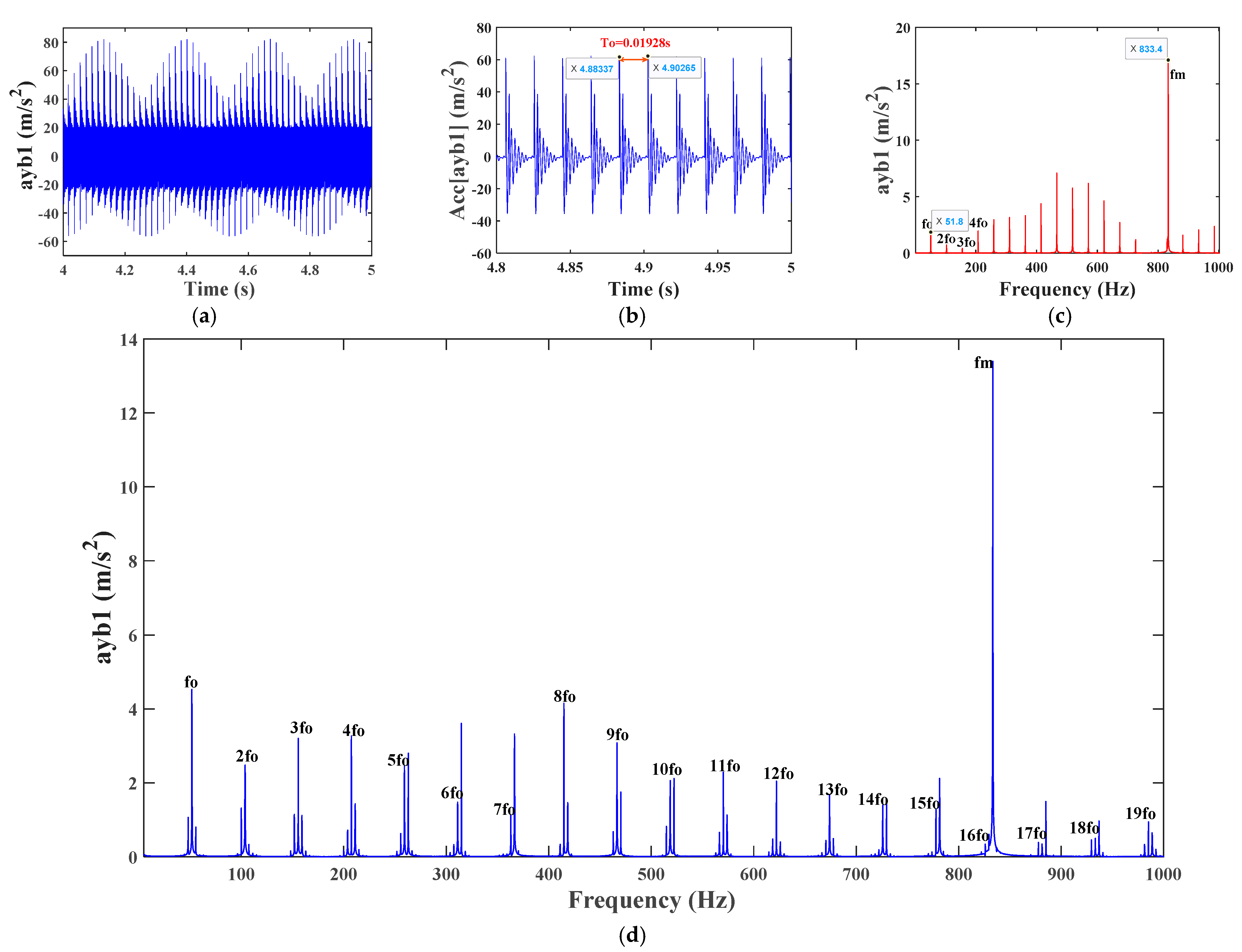
Set the fault parameters of the gears to 0, take the fault width of the bearing outer ring as 5 mm, and bring the bearing outer ring fault model Equation (47) into Equation (36) to solve the system vibration response, The vibration response of bearings in the 1-y direction of a single fault system with an outer ring is shown in Figure 21 (where a shows the time-domain response of bearings in the 1-y direction acceleration, Figure 21b shows the time-domain response of bearings in the 1-y direction acceleration residual, Figure 21c represents the corresponding frequency spectrum, and Figure 21d represents the envelope spectrum. The corresponding positions in the following figure have the same meaning as this section).
It can be seen from Figure 21a,b that compared with the corresponding health system response Figure 21a, when a local fault occurs in the outer ring of the bearing, the amplitude of the time-domain waveform of the system vibration increases significantly, and periodic impact vibration occurs. The time interval between the two impact peaks is T o ≈ 4.88337 − 4.90265 ≈ 0.01928 s, which corresponds to the characteristic frequency f o (1/0.01928) of the bearing outer ring fault, and also proves the accuracy of the model. From Figure 21c,d, it can be seen that the frequency domain components of the system with bearing outer ring faults are relatively simple. In addition to the gear meshing frequency f m , compared to Figure 13e,f, only the fault characteristic frequency f o and its doubling frequency n f o ( n = 1, 2, 3,…) of bearing 1 outer ring faults appear. This is due to the fixed outer ring of the bearing, and it also proves that the model of the nonlinear support force of the bearing with outer ring faults in this paper is reasonable.

4.2.4. Analysis of Vibration Characteristics of a Single Fault System of Bearing Inner Ring

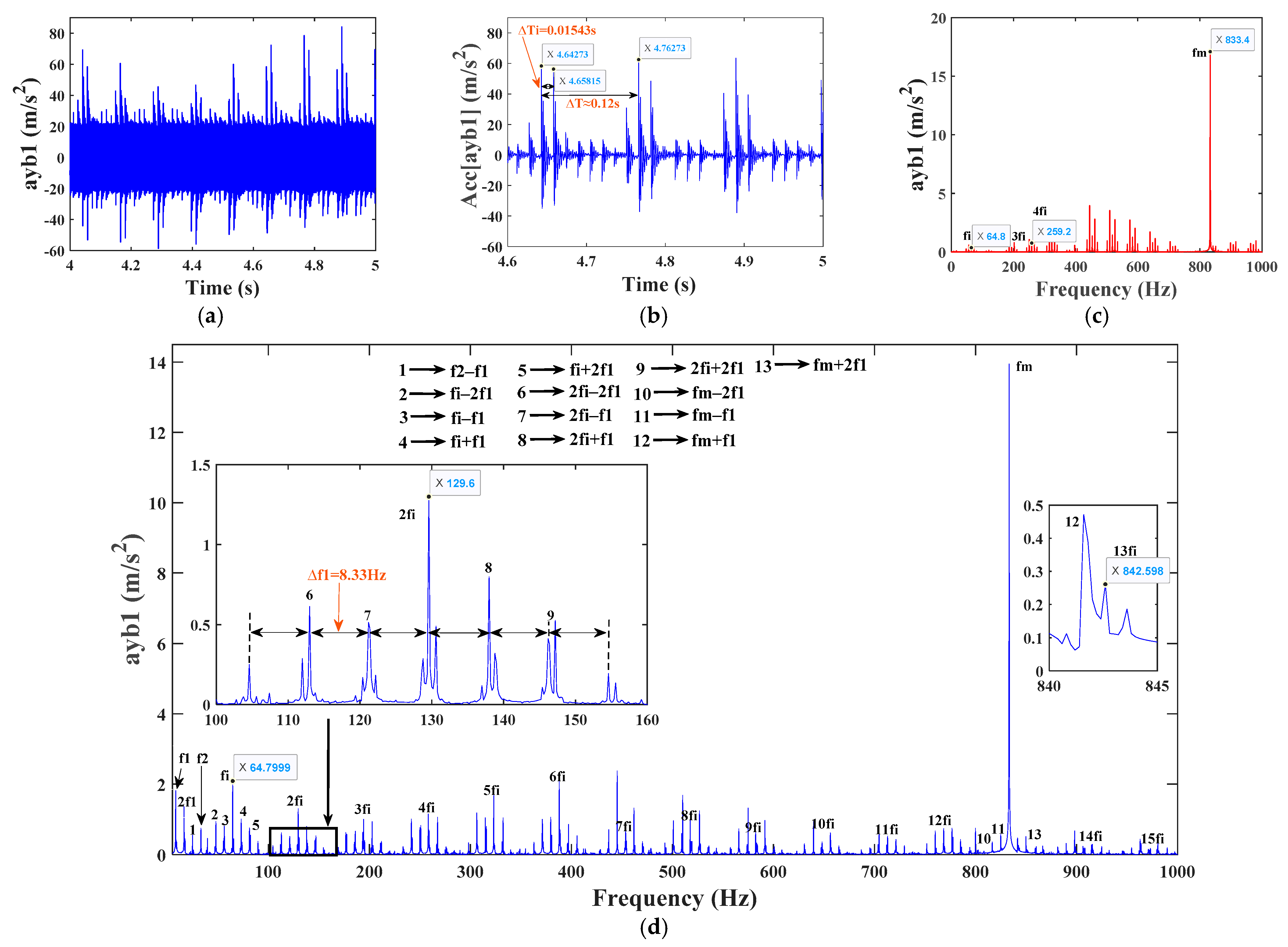
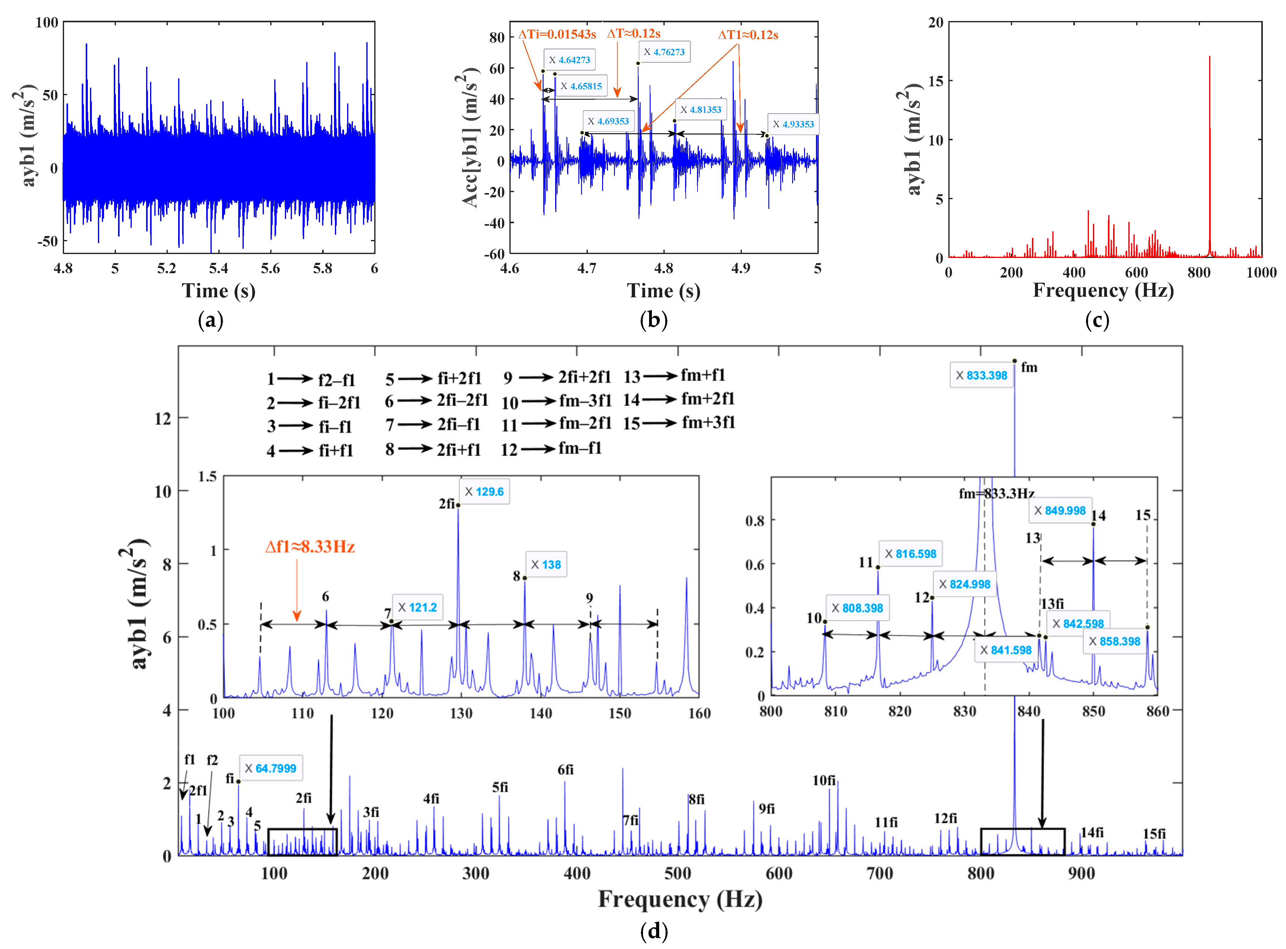
The fault parameters of the gear are set to 0, and the fault width of the bearing inner ring is 5 mm. The fault model Equation (50) of the bearing inner ring is substituted into Equation (36) to solve the vibration response of the system. The results are shown in Figure 22. Due to the fact that the failure of the bearing inner ring rotates with the shaft, the time-domain and frequency-domain responses of its vibration are more complex than those of a single failure of the bearing outer ring. If the fault is in the loading area, the vibration and impact generated will be more severe, resulting in higher amplitude. When the position of the inner ring fault passes through the loading area, its amplitude will decrease accordingly. By observing the envelope spectrum diagram (Figure 22d), it can be seen that the main frequency components of the single fault system with inner rings include not only the gear meshing frequency f m , the bearing inner ring fault characteristic frequency f i , and the doubling frequency n f i , but also the active shaft rotation frequency f 1 and doubling frequency n f 1 , and the driven shaft rotation frequency f 2 . In this case, the fault frequency of the inner ring is modulated by the rotation frequency (inner ring). There are also modulation frequency components with intervals of f 1 around f m , f i , and n f i , namely f m ± m f 1 , n f i ± m f 1 ( n , m = 1, 2, 3,…). The values of n and m in the following text are the same as in this section, and there will be no further explanation. From Figure 22b, it can be seen that the vibration impact interval is caused by the failure of the bearing outer ring T i = 4.65815 − 4.64273 ≈ 0.01543 s, which corresponds to the calculated characteristic frequency f i (1/0.01543) of the bearing inner ring fault in Table 4. At the same time, since the rotation of the driving shaft does not affect the location of the bearing inner ring fault, the impact of the inner ring fault will periodically change with the rotation of the shaft, and the repeated cycle Δ T = 4.76273 − 4.64273 ≈ 0.12 s is exactly the rotation frequency f 1 (1/0.12) of the active shaft, which also proves that the model with inner ring fault is reasonable.

4.2.5. Analysis of Vibration Characteristics of a Single Fault System of Bearing Rolling Element

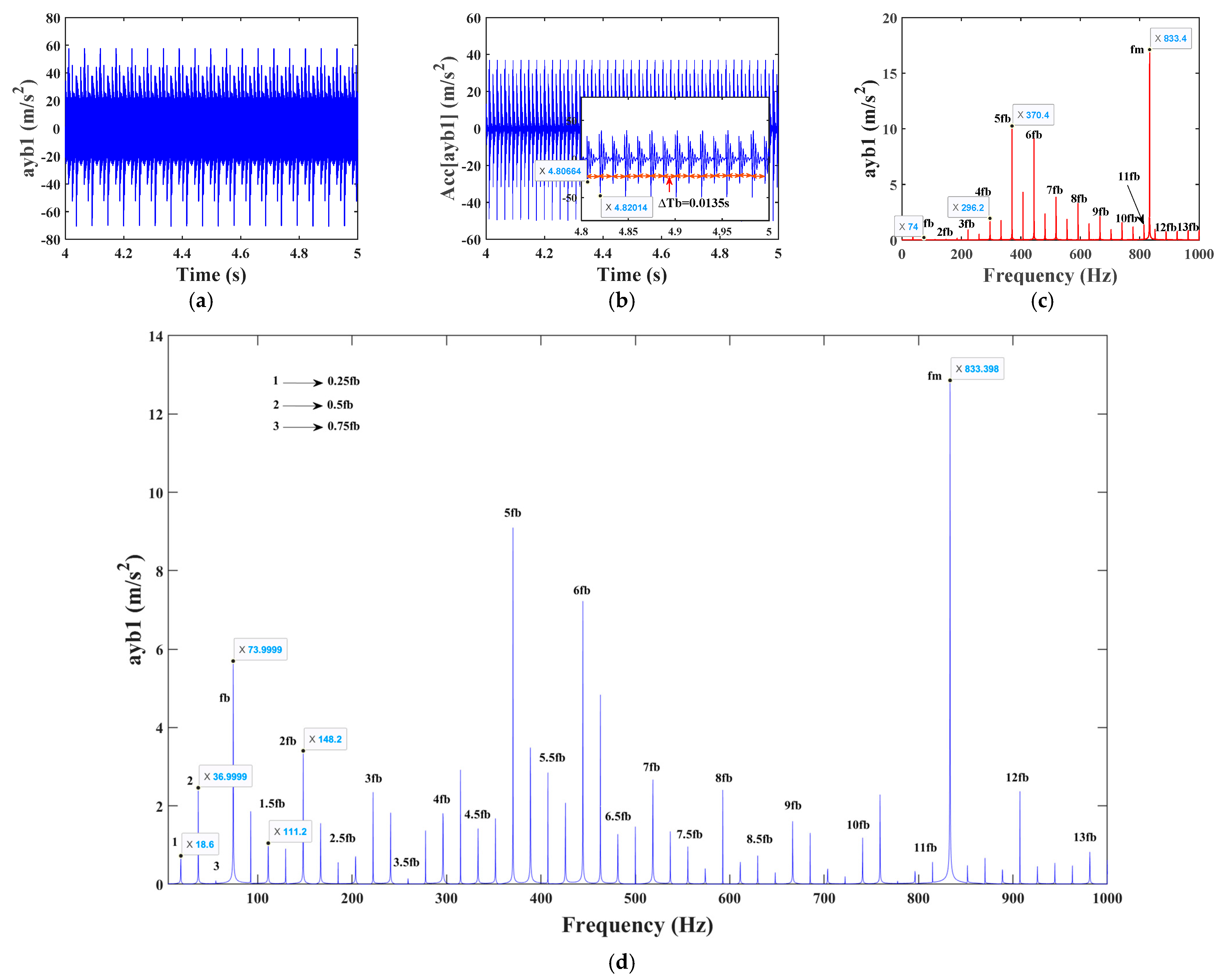
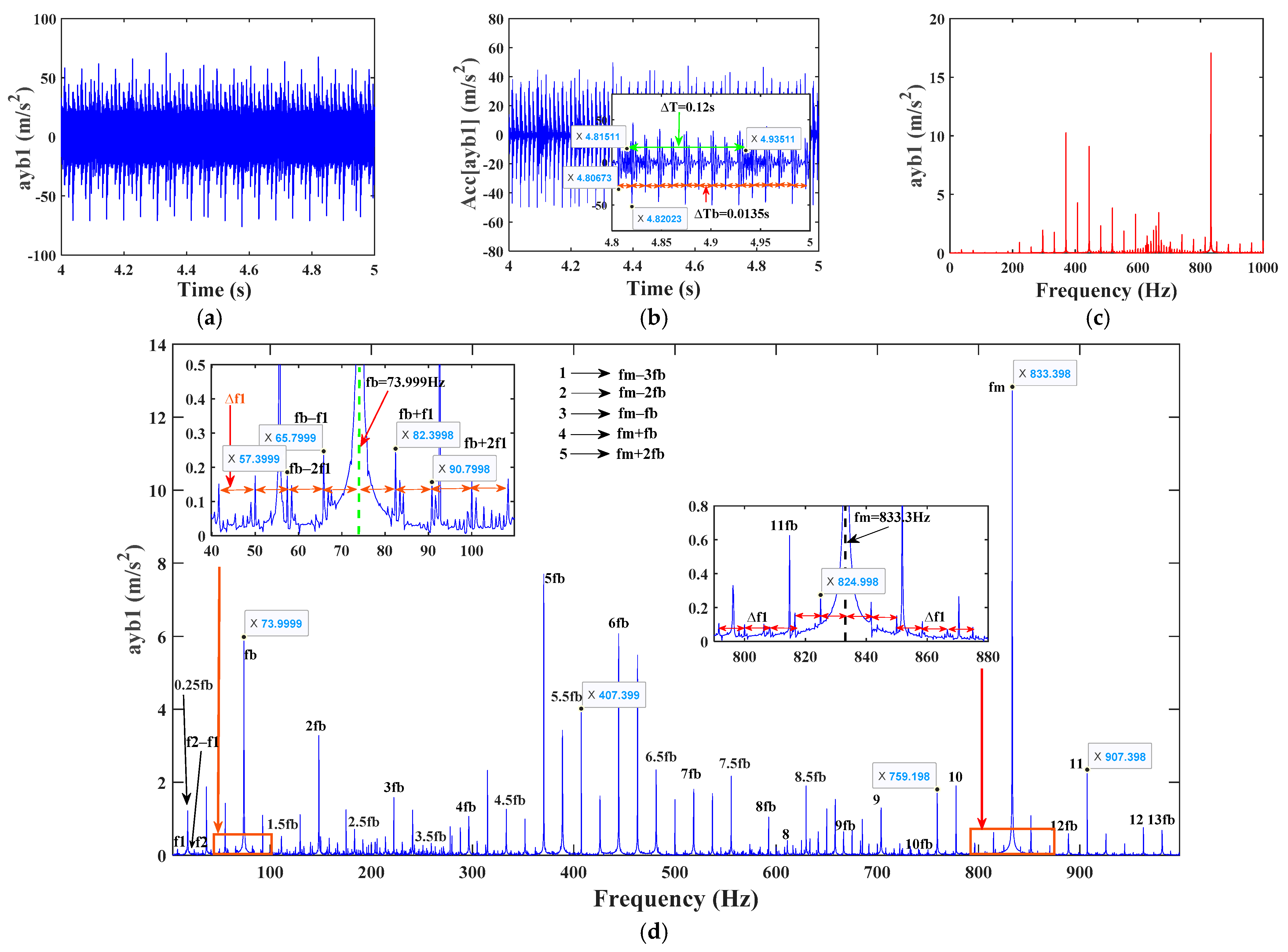
The gear fault parameter is set to 0, and the fault width of the bearing rolling element is set to 5 mm. The fault model Equation (53) of the bearing rolling element is substituted into Equation (36) to solve the system vibration response. As shown in Figure 23, due to the fact that the rolling element rotates with the cage and still rotates itself, the time and frequency domains of its vibration are also complex. When the bearing rolling element contains defects, it can be seen from the spectrum and envelope spectrum (Figure 23c,d) that the main frequencies of a single fault system containing rolling elements are the gear meshing frequency f m , the bearing rolling element fault characteristic frequency f b , and its higher harmonic frequency n f b . In addition, due to the collision strength of the rolling element when it contacts the outer ring at the fault location being greater than the collision with the inner ring, there will also be half-harmonic 0.5 f b (37 Hz) and quarter-harmonic 0.25 f b (18.5 Hz) components of f b . From Figure 23a,b, it can be seen that when a rolling element fault exists, the system generates significant vibration shocks with an interval time of T b = 4.82014 − 4.80664 ≈ 0.0135 s, which corresponds to the characteristic frequency f b (1/0.0135) of rolling element faults in Table 4, verifying the correctness of the response of the system with rolling element faults.

4.3. Analysis of Vibration Characteristics of a System with Composite Faults of Gears and Bearings

4.3.1. Vibration Response of a System with Root Cracks and Bearing Outer Ring Composite Faults

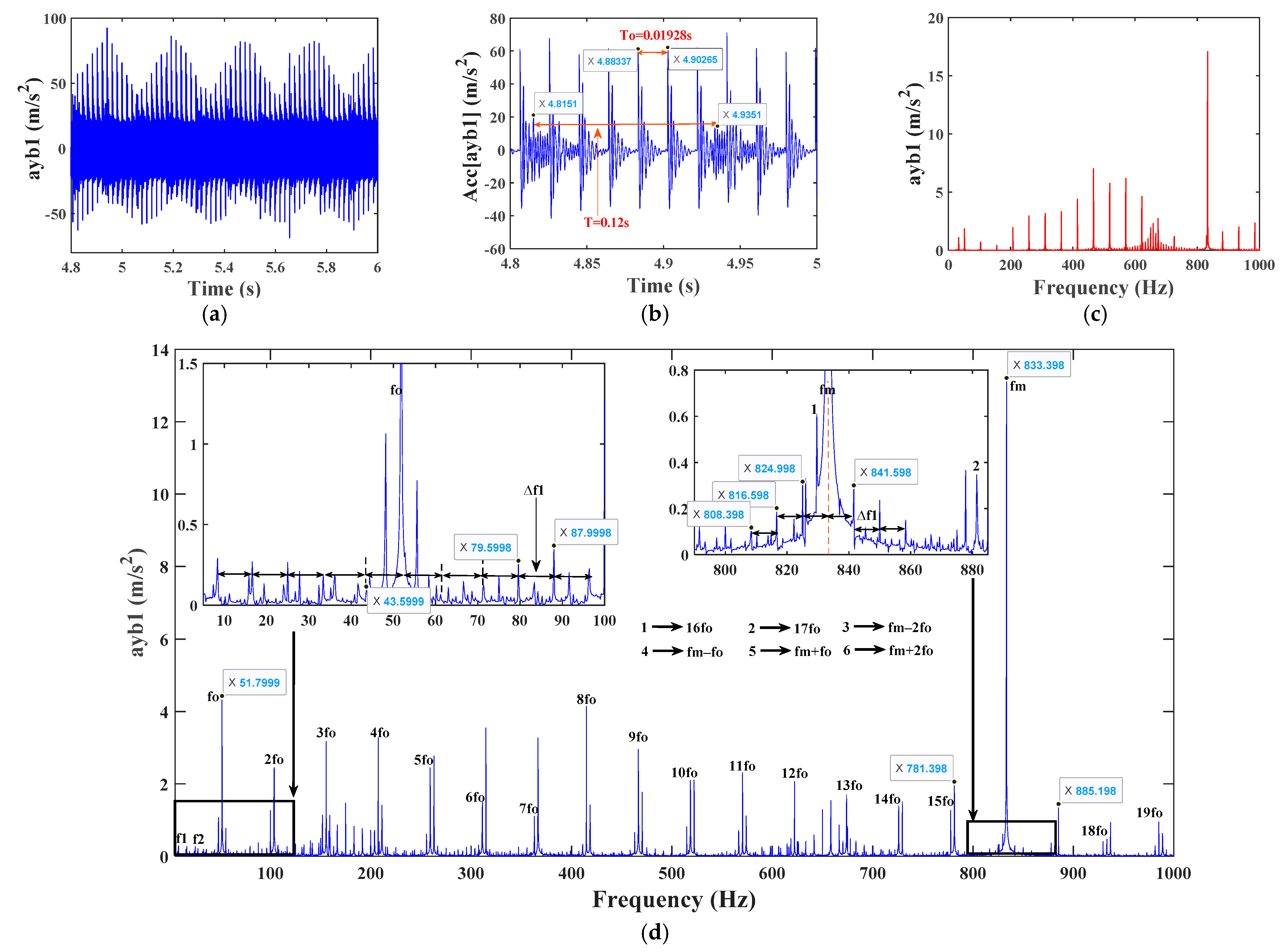
Based on Section 4.2.3, the vibration response of the system is solved by taking the gear crack depth of 15 mm. The y-direction vibration response of the bearing in the system with root crack fault and outer ring fault coupling is shown in Figure 24. From Figure 24a,b, it can be seen that compared to the response of the bearing outer ring single fault system, the time-domain vibration waveform of the system under coupled fault state becomes more complex. In addition to exhibiting the fault characteristics of the outer ring of the bearing, the vibration impact time interval also exhibits the fault characteristic time T = 0.12 s caused by tooth root cracks, which corresponds to the frequency f 1 (1/0.12) of the rotating shaft where the faulty gear is located. This is because the system in the composite fault state combines the single fault of tooth root cracks and the single fault of the outer ring of the bearing in terms of vibration characteristics. From Figure 24c,d, it can be seen that in addition to the gear meshing frequency and the outer ring fault frequency f o , 2 f o , 3 f o … of bearing 1, there are also obvious active shaft rotation frequency f 1 and its doubling frequency n f 1 ( n = 1, 2, 3,…). Due to the coupling effect of the system, there is also a combination frequency of gear meshing frequency and bearing fault characteristic frequency f m ± n f o , and a modulated sideband frequency with an interval of active gear rotation frequency ( Δ f 1 = 8.3 Hz) appears around f m and f o . This is formed by modulating the root crack fault characteristic frequency and bearing outer ring fault characteristic frequency with the shaft frequency, respectively. In summary, the main frequency components of the system with tooth root cracks and bearing outer ring coupling faults are f m , n f o , f m ± n f o , n f o m f 1 , and f m m f 1 .

4.3.2. Vibration Response of a System with Root Cracks and Bearing Inner Ring Composite Faults

On the basis of Section 4.2.4, the vibration response in the y-direction of the bearing in the system with a gear crack depth of 15 mm and coupling of root crack fault and inner ring fault is shown in Figure 25. By comparing Figure 25 and Figure 22, it can be seen that under the coupling effect of tooth root crack fault and bearing outer ring fault, the modulation signal of the system is severe, resulting in more complex time-domain and frequency-domain responses of the system. From the acceleration residual signal in the 1-y direction of bearing in Figure 25b, it can be seen that the vibration impact time interval in the signal not only has the fault characteristics of the bearing inner race but also has the fault characteristic T i = 0.12 s caused by tooth root cracks. From Figure 25d, it can be seen that the main frequency components of the system with composite faults are almost the same as those of the system with bearing inner ring faults. However, due to the coupling effect of tooth root crack fault and inner ring fault modulation side frequency, the amplitude of the side frequency increases, the distribution range widens, and there are many uncertain combination frequencies.

4.3.3. Vibration Response of a Composite Fault System with Root Cracks and Bearing Rolling Elements

On the basis of Section 4.2.5, the vibration response in the y-direction of the bearing in the system with a gear crack depth of 15 mm and coupling of root crack fault and rolling element fault is shown in Figure 26. When there is a coupling fault, the time interval between system vibration and impact, the rolling element fault feature T b = 0.0135, and the gear crack fault feature T = 0.12 s. From Figure 26d, it can be seen that the main frequencies of the coupling system with root crack faults and rolling element faults are gear meshing frequency f m , driving shaft rotation frequency f 1 , and doubling frequency n f 1 , driven shaft rotation frequency f 2 , combined frequency f 2 f 1 , bearing rolling element fault characteristic frequency f b = 74.07 Hz, and its doubling frequency n f b , and the combined frequency ( f m ± m f 1 , f m ± m f 2 , f m ± n f b , n f b ± m f 1 ) formed by the sideband frequency generated by fault coupling.

5. Conclusions

In order to study the response of a faulty helical gear-rotor-bearing transmission system and the influence of fault parameter changes on system response, the theoretical time-varying meshing stiffness of healthy and faulty helical gears with root cracks was obtained based on an improved energy method. A dynamic model of a composite fault helical gear-rotor-bearing transmission system was established considering multiple faults, and the vibration response of the system to various faults was discussed and analyzed. The conclusions drawn are as follows:
(1) Compared with the simulation results of KISSsoft software 2018 version, it was verified that the theoretical time-varying meshing stiffness of helical gears calculated by the improved energy method is reasonable and in line with reality. The time-varying meshing stiffness of the faulty gear solved based on the improved energy method is very close to the meshing stiffness of the fault-free helical gear simulated based on the KISSsoft method, and the improvement effect is obvious compared with the simulation results of the unimproved meshing stiffness;
(2) Under the consideration of internal and external excitations such as time-varying meshing stiffness of helical gears containing crack faults, nonlinear support force of three kinds of bearings with typical faults, eccentricity faults of gears, tooth-side clearance, transmission errors, etc., the dynamics model of the high degree-of-freedom composite faulty helical gear-rotor-bearing transmission system is established by the centralized parameter method and the vibration response of the system is solved;
(3) The existence of gear eccentricity and crack single faults will lead to the system response to generate fault characteristics, with the eccentricity and crack depth increasing the more obvious fault characteristics; master/slave gears have the same eccentricity fault, the smaller diameter gears caused by the system vibration is stronger; when the slave gear eccentricity distance is greater than 0.06 mm, the system time domain response of the indicators increased significantly. When the crack depth is less than 12.5 mm, the trend of curve change is weak, but when it is greater than 12.5 mm, the trend of both non-normalized and normalized statistical indicators increases sharply. This is because the closer the crack depth is to the centerline of the gear, the greater the stress concentration of the gear, resulting in a decrease in the gear’s bearing capacity. Therefore, gear crack faults should be diagnosed in a timely manner to avoid the fault extending to sensitive areas and causing irreversible accidents;
(4) When there is a single fault in the inner ring, outer ring, and rolling element of the bearing, the frequency domain response of the bearing in the system will have corresponding fault characteristic frequencies and their multiples. Compared to the corresponding health system response, when a local fault occurs in the outer ring of the bearing, the amplitude of the time-domain vibration waveform of the system significantly increases, and periodic impact vibration is generated. Due to the fact that the failure of the bearing inner ring rotates with the shaft, the time-domain and frequency-domain responses of its vibration are more complex than those of a single failure of the bearing outer ring. If the fault is located in the loading area, the vibration impact generated will be more severe, resulting in higher amplitude. When the position of the inner ring fault rotates past the loading area, its amplitude will decrease accordingly;
(5) When tooth root cracks and composite faults occur in the helical gear-rotor-bearing system, as well as in the inner race, outer race, and rolling element of the bearing, the time-domain and frequency-domain signal characteristics of the system vibration are obvious. The time domain includes both periodic pulse impacts caused by gear faults and impacts caused by bearings, and the fault characteristic frequency can also be found in the frequency domain. The vibration characteristics of the system with composite faults are significantly different from those of healthy and single-fault systems. Compared to the response of a single fault system on the outer ring of a bearing, the time-domain vibration waveform of the system under coupled fault conditions becomes more complex. The vibration impact time interval not only shows the fault characteristics of the outer ring of the bearing but also shows the fault characteristics caused by tooth root cracks. Under the coupling effect of tooth root crack fault and bearing inner ring fault, the modulation signal of the system is severe, resulting in more complex time-domain and frequency-domain responses of the system. The vibration impact time interval in the signal not only exhibits the characteristics of bearing inner ring faults but also the fault characteristics caused by tooth root cracks. Due to the coupling effect of tooth root crack faults and inner ring fault modulation edge frequencies, the amplitude of edge frequencies increases, the distribution range becomes wider, and many uncertain combination frequencies appear;
(6) By analyzing the vibration response of the system, the main frequency components at the bearings of the system under different composite states were obtained. The research results can provide a reference basis for the theoretical analysis of the vibration characteristics of the helical gear-rotor-bearing system under various fault conditions and also lay a solid foundation for the simulation of the system with composite fault signals and subsequent diagnosis.

Author Contributions

Conceptualization, H.Z. and S.L.; methodology, H.Z. and S.L.; software, S.L.; validation, H.Z. and H.S.; formal analysis, S.L.; investigation, H.Z., S.L. and H.S.; resources, H.Z.; data curation, H.Z., S.L. and H.S.; writing—original draft preparation, S.L.; writing—review and editing, H.Z. and H.S.; supervision, H.Z.; project administration, H.Z.; funding acquisition, H.Z. All authors have read and agreed to the published version of the manuscript.

Funding

This research was funded by basic scientific research projects of the Liaoning Provincial Department of Education (JYTMS20230216), the construction plan of the scientific research and innovation team of Shenyang Ligong University (SYLU202101).

Data Availability Statement

The datasets generated during and/or analyzed during the current study are available from the corresponding author upon reasonable request.

Conflicts of Interest

The authors declare no conflicts of interest.

Nomenclature

k h Hertz contact stiffness
k b Bending stiffness
k s Shear stiffness
k a Axial compression stiffness
k f Elastic stiffness of matrix
U h Hertz contact deformation potential energy
U b Bending deformation potential energy
U s Shear deformation potential energy
U a Axial deformation potential energy
F The meshing force in the meshing line direction
E Young’s modulus
G Shear modulus
μ Poisson ratio
d The distance from the meshing point to the base circle
h The distance from the meshing point to the centerline of the gear
B Tooth width
I x The distance of inertia of the tooth from the cross-section at the base circle x
A x The cross-sectional area of the tooth from the cross-section at the base circle x
h x The distance from the point at the base circle x from the centerline of the single tooth of the gear
α 1 The angle between the meshing force and the direction of the perpendicular line of the centerline of the gear
r 0 The radius of the root transition curve
α f The root circle pressure angle
q The crack depth
v The crack angle
h c 1 The perpendicular distance from the crack tip to the gear centerline
Z 1 ,   Z 2 Number of teeth
α n Pressure angle
β Spiral angle
m n modulus
m 1 ,   m 2 The mass of helical gear
J 1 ,   J 2 The moment of inertia relative to the center of mass
ρ 1 ,   ρ 2 The eccentricity
r b 1 ,   r b 2 The base circle radius
F t Respectively, the tangential force
F r Radial force
F a Rxial force
θ d ,   θ 1 ,   θ 2 ,   θ l The torsional vibration angular displacement of the input device, the driving and driven gears, and the load, respectively
G 1 ,   G 2 The center of mass
O 1 ,   O 2 The center of rotation
x i , y i , z i The horizontal, vertical, and axial vibrational displacements of the driving and driven gears, respectively
e 0 The mean value of error
e 1 The amplitude of error
v i ,   v o The linear velocity of the contact points between the rolling elements and the inner and outer rings of the bearing
ω i ,   ω 0 Angular velocity of the inner and outer rings of the bearing
N b The number of bearing rollers
α 12 The angle at which the gear is located
d b The rolling body diameter of the bearing
d The diameter of the axis
d i ,   d o Groove diameters of inner/outer rings of bearings, respectively
d m The pitch diameter of the bearing
A , A The distance between the centers of curvature of the grooves of the inner and outer rings of the bearing before and after loading
α 0 ,   α 0 The contact angles before and after loading
P 0 ,   P 0 The position of bearing outer ring raceway curvature center before/after the force, respectively, because the bearing outer ring is fixed
P i ,   P i The position of the center of curvature of the inner ring raceway of the bearing before/after the force, respectively
δ a i ,   δ r i ,   θ i The radial deformation, axial deformation, and angular deformation caused by the force and torque, respectively
R i The radius of the inner ring raceway curvature center track
δ i ,   δ 0 ,   δ b i The contact deformation and total deformation of the inner and outer channel of the ball bearing, respectively
h d The additional displacement caused by localized bearing failure
A The distance between the initial inner and outer ring channel curvature centers
K c The Hertzian contact stiffness
H x The Heaviside function
F b x ,   F b y ,   F b z The component of the nonlinear support force generated by angular contact ball bearings in three directions
L di ,   L do ,   h di ,   h do The diameter and depth of the inner and outer ring fault areas are represented
Δ h di ,   Δ h do The actual depths at which the rolling element of the bearing falls into the inner and outer rings of the bearing
θ i e ,   θ o e Half of the center angles corresponding to the inner and outer fault areas
θ i d ,   θ o d The rotation angles of the center of the damaged area in the inner and outer rings
R b 1 The radius of the rolling element
ω s The rotational speed of the rolling element
k s x i ,   k s y i ,   k s z i Bending stiffness of the main and driven shafts
k t 1 , k t 2 Torsional stiffness of driven shafts and driven shafts
c s x i ,   c s y i ,   c s z i Bending damping of main and driven shafts
c t 1 , c t 2 Torsional damping of the main and driven shafts
c b x i ,   c b y i ,   c b z i Damping in the direction of the bearing
F b x i ,   F b y i ,   F b z i Nonlinear support force in the direction of the bearing

References

  1. Li, Y.; Yuan, S.; Wu, W.; Liu, K.; Lian, C.; Song, X. Vibration Analysis of Two-Stage Helical Gear Transmission with Cracked Fault Based on an Improved Mesh Stiffness Model. Machines 2022, 10, 1052. [Google Scholar] [CrossRef]
  2. Wu, G.; Wu, H.; Li, D. Review of Automotive Transmission Gear Rattle. J. Tongji Univ. (Nat. Sci. Ed.) 2016, 44, 276–285. (In English) [Google Scholar]
  3. Chen, X.F.; Li, J.M.; Cheng, H.; He, Z.J. Research and Development of Condition Monitoring and Fault Diagnosis Technology for Wind Turbines. J. Mech. Eng. 2011, 47, 45–52. (In Chinese) [Google Scholar] [CrossRef]
  4. Hu, Z.; Tang, J.; Zhong, J.; Chen, S.; Yan, H. Effects of tooth profile modification on dynamic responses of a high speed gear-rotor-bearing system. Mech. Syst. Signal Process. 2016, 76, 294–318. [Google Scholar] [CrossRef]
  5. Liu, J.; Zhao, W.; Liu, W. Frequency and vibration characteristics of high-speed gear-rotor-bearing system with tooth root crack considering compound dynamic backlash. Shock. Vib. 2019, 2019, 1854263. [Google Scholar] [CrossRef]
  6. Yang, D.C.H.; Lin, J.Y. Hertzian damping, tooth friction and bending elasticity in gear impact dynamics. J. Mech. Des. 1987, 109, 189–196. [Google Scholar] [CrossRef]
  7. Wu, S.; Zuo, M.J.; Parey, A. Simulation of spur gear dynamics and estimation of fault growth. J. Sound Vib. 2008, 317, 608–624. [Google Scholar] [CrossRef]
  8. Wan, Z.; Cao, H.; Zi, Y.; He, W.; Chen, Y. Mesh stiffness calculation using an accumulated integral potential energy method and dynamic analysis of helical gears. Mech. Mach. Theory 2015, 92, 447–463. [Google Scholar] [CrossRef]
  9. Ma, H.; Song, R.; Pang, X.; Wen, B. Time-varying mesh stiffness calculation of cracked spur gears. Eng. Fail. Anal. 2014, 44, 179–194. [Google Scholar] [CrossRef]
  10. Huangfu, Y.F.; Chen, K.K.; Ma, H.; Che, L.; Li, Z.; Wen, B. Deformation and meshing stiffness analysis of cracked helical gear pairs. Eng. Fail. Anal. 2019, 95, 30–46. [Google Scholar] [CrossRef]
  11. Huangfu, Y.F.; Chen, K.K.; Ma, H.; Li, X.; Han, H.; Zhao, Z. Meshing and dynamic characteristics analysis of spalled gear systems, A theoretical and experimental study. Mech. Syst. Signal Process. 2020, 139, 106640. [Google Scholar] [CrossRef]
  12. Choy, F.K.; Ruan, Y.F.; Tu, R.K.; Zakrajsek, J.J.; Townsend, D.P. Modal analysis of multistage gear systems coupled with gearbox vibrations. J. Mech. Des. 1992, 114, 486–497. [Google Scholar] [CrossRef]
  13. Howard, I.; Jia, S.; Wang, J. The dynamic modelling of a spur gear in mesh including friction and a crack. Mech. Syst. Signal Process. 2001, 15, 831–853. [Google Scholar] [CrossRef]
  14. Jia, S.; Howard, I. Comparison of localised spalling and crack damage from dynamic modelling of spur gear vibrations. Mech. Syst. Signal Process. 2006, 20, 332–349. [Google Scholar] [CrossRef]
  15. Ma, H.; Li, Z.; Feng, M. Time-varying mesh stiffness calculation of spur gears with spalling defect. Eng. Fail. Anal. 2016, 66, 166–176. [Google Scholar] [CrossRef]
  16. Wan, Z.; Cao, H.; Zi, Y.; He, W.; He, Z. An improved time-varying mesh stiffness algorithm and dynamic modeling of gear-rotor system with tooth root crack. Eng. Fail. Anal. 2014, 42, 157–177. [Google Scholar] [CrossRef]
  17. Han, L.; Qi, H. Dynamics responses analysis in frequency domain of helical gear pair under multi-fault conditions. J. Mech. Sci. Technol. 2019, 33, 5117–5127. [Google Scholar] [CrossRef]
  18. Ma, H.; Song, R.; Pang, X.; Wen, B. Fault feature analysis of a cracked gear coupled rotor system. Math. Probl. Eng. 2014, 2014, 832192. [Google Scholar] [CrossRef]
  19. Cui, L.; Cai, C. Nonlinear dynamics analysis of a gear-shaft-bearing system with breathing crack and tooth wear faults. Open Mech. Eng. J. 2015, 9, 483–491. [Google Scholar] [CrossRef]
  20. Liang, X.; Zuo, M.J.; Feng, Z. Dynamic modeling of gearbox faults: A review. Mech. Syst. Signal Process. 2018, 98, 852–876. [Google Scholar] [CrossRef]
  21. Zhao, Q.; Wang, X.; Li, T.; Zhang, H. Analysis of coupling fault correlation and nonlinear vibration of multi-stage gear transmission system. J. Vibroeng. 2021, 23, 114–126. [Google Scholar] [CrossRef]
  22. Cao, P.; Li, Q.; Feng, K.; Qin, Y. Dynamic modeling of spur gear transmission system with evolutive coupling fault of fatigue crack and wear. Eng. Fail. Anal. 2024, 156, 107820. [Google Scholar] [CrossRef]
  23. Dai, P.; Wang, J.; Yan, S.; Jiang, B.; Wang, F.; Niu, L. Effects of localized defects of gear-shaft-bearing coupling system on the meshing stiffness of gear pairs. J. Vib. Eng. Technol. 2022, 10, 1153–1173. [Google Scholar] [CrossRef]
  24. Patel, V.N.; Tandon, N.; Pandey, R.K. A dynamic model for vibration studies of deep groove ball bearings considering single and multiple defects in races. J. Tribol. 2010, 132, 041101. [Google Scholar] [CrossRef]
  25. Patel, U.K.A.; Upadhyay, S.H. Nonlinear dynamic response of cylindrical roller bearing–rotor system with 9 degree of freedom model having a combined localized defect at inner–outer races of bearing. Tribol. Trans. 2017, 60, 284–299. [Google Scholar] [CrossRef]
  26. Jafari, S.M.; Rohani, R.; Rahi, A. Experimental and numerical study of an angular contact ball bearing vibration response with spall defect on the outer race. Arch. Appl. Mech. 2020, 90, 2487–2511. [Google Scholar] [CrossRef]
  27. Cheng, H.; Zhang, Y.; Lu, W.; Yang, Z. Research on time-varying stiffness of bearing based on local defect and varying compliance coupling. Measurement 2019, 143, 155–179. [Google Scholar] [CrossRef]
  28. Ogundare, A.A.; Ojolo, S.J.; Adelaja, A.; Mba, D.; Zhou, L.; Li, X. Study of the Vibration Characteristics of SA 330 Helicopter Planetary Main Gearbox. J. Appl. Comput. Mech. 2023, 9, 1093–1106. [Google Scholar]
  29. Li, C.F.; Zhou, S.H.; Liu, J. Coupled lateral-torsional-axial vibrations of a helical gear-rotor-bearing system. Acta Mech. Sin. 2014, 30, 746–761. [Google Scholar] [CrossRef]
  30. Sharma, V.; Parey, A. A review of gear fault diagnosis using various condition indicators. Procedia Eng. 2016, 144, 253–263. [Google Scholar] [CrossRef]
  31. Reuben, L.C.K.; Mba, D. Bearing time-to-failure estimation using spectral analysis features. Struct. Health Monit. 2014, 13, 219–230. [Google Scholar] [CrossRef]
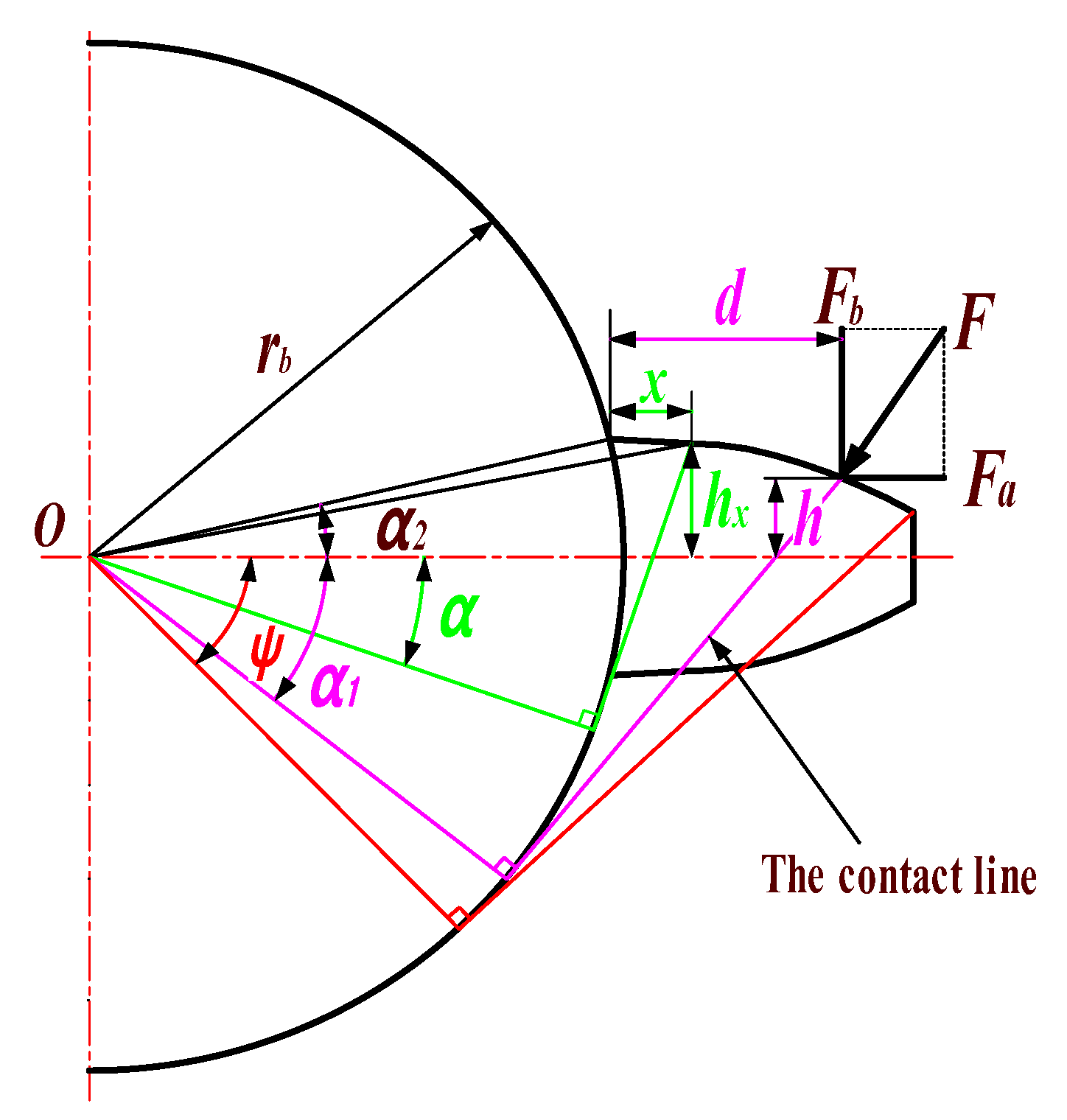
Figure 1. Spur gear cantilever beam model.
Mathematics 12 01410 g001
Figure 2. Sliced model of helical gear cantilever beam for r b > r f .
Mathematics 12 01410 g002
Figure 3. Sliced model of helical gear cantilever beam for r b < r f .
Mathematics 12 01410 g003
Figure 4. Sliced view of a cracked helical gear. (a) r b > r f (b) r b < r f .
Mathematics 12 01410 g004
Figure 5. Sliced cantilever beam model of crack-failed helical gear for r b > r f . (a) r b > r f , h c 1 h r and α 1 α g (b) r b < r f , h c 1 < h r or h c 1 < h r , α 1 < α g .
Mathematics 12 01410 g005
Figure 6. Sliced cantilever beam model of crack-failed helical gear for r b < r f . (a) r b < r f , h c 1 h r and α 1 α g (b) r b < r f , h c 1 < h r or h c 1 > h r , α 1 > α g .
Mathematics 12 01410 g006
Figure 7. Verification of time-varying meshing stiffness of faulty helical gears.
Mathematics 12 01410 g007
Figure 8. Dynamic model of faulty helical gear-rotor-bearing transmission system.
Mathematics 12 01410 g008
Figure 9. Diagram of angular contact ball bearing.
Mathematics 12 01410 g009
Figure 10. Geometric deformation at different positions of the rolling element (a) before loading; (b) after loading; (c) geometric deformation relationship.
Mathematics 12 01410 g010
Figure 11. Schematic diagram of bearing inner and outer ring faults.
Mathematics 12 01410 g011
Figure 12. Schematic diagram of bearing rolling element failure.
Mathematics 12 01410 g012
Figure 13. Time-domain waveforms, frequency spectra, and envelope spectra of driving gears and. bearings 1 in y-direction. (a) Time-domain waveforms of gear; (b) Frequency spectra of gear; (c) Envelope spectra of gear (d); Time-domain waveforms of bearings; (e) Frequency spectra of bearings; (f) Envelope spectra of bearings.
Mathematics 12 01410 g013
Figure 14. y-direction time domain/frequency domain response of follower gear, bearing 1 when ρ 1 = 0 mm, ρ 2 = 0.15 mm. (a) Time-domain waveforms of gear; (b) Frequency spectra of gear (c); Envelope spectra of gear (d) Time-domain waveforms of bearings; (e) Frequency spectra of bearings; (f) Envelope spectra of bearings.
Mathematics 12 01410 g014
Figure 15. y-direction time domain/frequency domain response of follower gear, bearing 1 when ρ 1 = 0.15 mm, ρ 2 = 0 mm. (a) Time-domain waveforms of gear; (b) Frequency spectra of gear (c); Envelope spectra of gear (d) Time-domain waveforms of bearings; (e) Frequency spectra of bearings; (f) Envelope spectra of bearings.
Mathematics 12 01410 g015
Figure 16. y-direction response residual comparison of driving gear, bearing 1.
Mathematics 12 01410 g016
Figure 17. Comparison of sensitivity of different statistical indicators to the degree of eccentricity fault. (a) Non-normalized (b) Normalized.
Mathematics 12 01410 g017
Figure 18. ydirection and torsion time/frequency domain response of crack-containing faulty active gear and bearing.
Mathematics 12 01410 g018
Figure 19. Comparison of time domain/frequency domain response residuals in the y-direction of failed driving gears with different crack depths. (a) Time domain waveform residual diagram of gears (b) Frequency residual diagram of gears (c) Comparison of time–domain waveforms of driving gears (d) Comparison of spectrograms of driving gears.
Mathematics 12 01410 g019
Figure 20. Comparison of the sensitivity of different statistical indicators to the degree of cracking. (a) Non-normalized (b) Normalized.
Mathematics 12 01410 g020
Figure 21. Vibration response in the y-direction during a single failure of the outer ring of bearing 1. (a) Time–domain waveforms of bearings (b) Time–domain waveforms residual diagram of bearings (c) Spectrum diagram of bearings (d) Envelope spectrum of bearings.
Mathematics 12 01410 g021
Figure 22. Vibration response in the y-direction during a single failure of the inner ring of bearing 1. (a) Time–domain waveforms of bearings (b) Time–domain waveforms residual diagram of bearings (c) Spectrum diagram of bearings (d) Envelope spectrum of bearings.
Mathematics 12 01410 g022
Figure 23. Vibration response in the y-direction when a single fault occurs in the rolling element of bearing 1. (a) Time–domain waveforms of bearings (b) Time–domain waveforms residual diagram of bearings (c) Spectrum diagram of bearings (d) Envelope spectrum of bearings.
Mathematics 12 01410 g023
Figure 24. Vibration response of the bearing 1 in the y-direction for the composite failure of root crack and outer ring. (a) Time–domain waveforms of bearings (b) Time–domain waveforms residual diagram of bearings (c) Spectrum diagram of bearings (d) Envelope spectrum of bearings.
Mathematics 12 01410 g024
Figure 25. Vibration response of the bearing 1 in the y-direction for the composite failure of root crack and inner ring. (a) Time–domain waveforms of bearings (b) Time–domain waveforms residual diagram of bearings (c) Spectrum diagram of bearings (d) Envelope spectrum of bearings.
Mathematics 12 01410 g025
Figure 26. Vibration response of the bearing 1 in the y-direction for the composite failure of root crack, eccentricity, and bearing rolling body. (a) Time–domain waveforms of bearings (b) Time–domain waveforms residual diagram of bearings (c) Spectrum diagram of bearings (d) Envelope spectrum of bearings.
Mathematics 12 01410 g026
Table 1. Gear parameters.
Parameter NameParameter Symbol Value
Number of teeth Z 1 ,   Z 2 data
Pressure angle α n /(°)20
Spiral angle β /(°)15
modulus m n 8
Tooth width B /(mm)120
Poisson’s ratio μ 0.25
modulus of elasticity E /(Gpa)207
Table 2. Remaining partial parameters of the gear.
Parameter NameParameter Symbol Value
Driving/Driven gear mass m 1 ,   m 2 /(kg)668, 141
Rotational inertia of driving/driven gear J 1 ,   J 2 / ( kg · m2)44.35, 0.21
Meshing damping ratio ξ m 0.1
Error mean/magnitude value e 1 ,   e 0 /(m) 2   ×   10 5 ,   2   ×   10−5
Lateral clearance b /(um)10
Table 3. Axis parameters.
Parameter NameParameter Symbol Value
Shaft I and II bending stiffness k s 1 ,   k s 2 ,   k s 3 ,   k s 4 / ( N · m−1)6 × 10⁸, 6 × 10⁸, 1.5 × 10⁸, 1.5 × 10⁸
Bending damping ratio ξ s 0.07
Shaft I and II torsional stiffness k t 1 ,   k t 2 / ( N · m−1)8 × 10⁸, 1.5 × 10⁸
Torsional damping ratio ξ t 0.07
Moment of inertia of the driving and load device J d ,   J l / ( kg · m2)20, 5
Input and output revolutions n 1 ,   n 2 / ( r · min−1)500, 2000
Table 4. Fault characteristic frequency of bearings.
ParametersBearing 1/Bearing 2Bearing 3/Bearing 4
n 1 / n 2 (r/min)5002000
f r /Hz8.3333.33
f o /Hz51.85148.15
f i /Hz64.81185.19
f b /Hz74.07296.30
Disclaimer/Publisher’s Note: The statements, opinions and data contained in all publications are solely those of the individual author(s) and contributor(s) and not of MDPI and/or the editor(s). MDPI and/or the editor(s) disclaim responsibility for any injury to people or property resulting from any ideas, methods, instructions or products referred to in the content.