Article

Computationally Efficient Design of 16-Poles and 24-Slots IPMSM for EV Traction Considering PWM-Induced Iron Loss Using Active Transfer Learning

1
Department of Mechanical, Robotics, and Energy Engineering, Dongguk University, Seoul 04620, Republic of Korea
2
Department of Automotive Engineering, Hanyang University, Seoul 04763, Republic of Korea
*
Author to whom correspondence should be addressed.
Mathematics 2025, 13(6), 915; https://doi.org/10.3390/math13060915
Submission received: 14 January 2025 / Revised: 3 March 2025 / Accepted: 4 March 2025 / Published: 10 March 2025
(This article belongs to the Special Issue Artificial Intelligence for Fault Detection in Manufacturing)

Abstract

:
The efficiency of the traction motor is highly concerned with the PWM-induced iron loss, so the PWM-induced iron loss should be considered in designing the traction motor. However, analyzing the PWM-induced iron loss requires a high computational cost because the inverter-motor model should be included in the calculation process. In surrogate-based design optimization, collecting a large amount of data is essential. However, for PWM-induced iron loss, extremely small time steps are required to accurately capture high-frequency components, resulting in a significantly high computational cost for data acquisition and making the optimization process inefficient. From this point of view, we propose a computationally efficient design process for the traction motor considering the PWM-induced iron loss. By using the proposed method, it is possible to train the accurate surrogate model for predicting the PWM-induced iron loss with a small amount of PWM-induced iron loss using active transfer learning. After training the surrogate model, multi-objective optimization was conducted for designing a high efficiency 14.5 kW traction motor for personal mobility. In order to verify the design result, an optimized traction motor was fabricated, and experiments were conducted. As a result, the performance of the trained surrogate model was verified by measuring the no-load back electromotive force, PWM current, and main drive efficiency.

1. Introduction

Interior permanent magnet synchronous motors (IPMSMs) are widely used in the automotive industry because of their suitable characteristics for the high-speed trend in electric powertrains (e-powertrain) and their strong field-weakening characteristics due to a high saliency rotor structure [1,2]. As the era of electric vehicles (EVs) arrives, the mileage of EVs is being used as a major indicator to determine their competitiveness [3]. The e-powertrain consists of a battery, inverter, converter, traction motor, and reducer. Each component serves to convert and transfer the electrical energy stored in the battery into mechanical energy [3]. During the energy conversion, electromagnetic and mechanical energy losses occurs in the e-powertrain [4]. Therefore, the improvement of mileage can be categorized in two ways. The first way is to improve the energy density of the battery or enhance the capacity of the battery [5,6]. Since the energy stored in the battery is the same as the fuel of an ICE, the mileage can be improved by increasing the energy density or quantity of the battery. However, there is a limitation because it leads to increase in the weight and price of EVs. Therefore, it is more efficient to use the other method, which is to improve the efficiency of the e-powertrain for enhancing the mileage of EVs [7,8].
The terminal voltage of the traction motor is supplied by pulse width modulation (PWM) voltage with a fixed or variable switching frequency [9]. Therefore, the PWM current in the stator windings contains high-order harmonics near the PWM bands with a low-frequency fundamental wave when the traction motor is operated at low speed. On the other hand, the PWM current contains low-order PWM harmonics with a high-frequency fundamental wave when the traction motor is operated at high rotational speed. As the harmonics in current waveform cause the additional iron loss in the core material, the PWM current waveform should be considered when designing the high-efficiency traction motor, which is operated in a wide speed range. Therefore, the effect of switching frequency on PWM-induced iron loss was analyzed in various studies [10,11].
Since the PWM current affects a variation in the magnetic flux density of the stator and rotor core, it has a great influence on the iron loss [12]. Therefore, the PWM current waveform can be predicted by integrating the nonlinear motor model constructed using electromagnetic finite element analysis (FEA) and the inverter model with control logic [13,14,15,16]. In order to calculate the PWM-induced iron loss, individual FEA should be performed for PWM current with a small time step because the current waveform differs depending on the rotational speed, whereas the sinusoidal current-based iron loss requires a single FEA for each current vector with the frequency scaling method [17]. Yamazaki et. al investigated the iron loss of IPMSMs according to the driving condition and segregated the iron loss into components by fundamental wave and PWM carriers [18]. For this reason, the PWM-induced iron loss considering the drive cycle was excluded in the design stage due to the high computational cost in the conventional studies.
The traction motor should be designed with consideration of various factors such as material cost, size, noise and vibration, and efficiency [19,20]. Therefore, multi-objective optimization algorithms such as particle swarm optimization or genetic algorithms are generally used for the optimization of traction motors [21,22]. The optimization is generally performed using surrogate models trained with 2-D electromagnetic FEA data for efficient computation in the design of the traction motor. Many studies have performed design optimization by constructing surrogate models to calculate the performance of the motor according to geometry variation. Shimizu et al. performed the design of IPMSM with minimized magnet volume considering the demagnetization characteristics based on a surrogate model using the Gaussian process [23]. Refs. [24,25,26] investigated the surrogate model for predicting various motor performances using machine learning models and deep neural networks (DNNs). Since the training of the surrogate model requires a large amount of data, reducing the computational cost for data acquisition is important in terms of improving the efficiency of deriving the optimal design.
From this point of view, this paper proposes a computationally efficient design process for traction motors considering PWM-induced iron loss. The most challenging issue in designing electric machines is the discrepancy between the optimal model that accounts for PWM supply and the sinusoidal current-driven model. However, minimizing this discrepancy is difficult due to the high computation cost associated with considering PWM supply. Therefore, it is inefficient to consider the PWM-induced iron loss due to its high computation cost of data acquisition. Therefore, the active transfer learning-based training process of the surrogate model was proposed to reduce the computational cost for analyzing PWM-induced iron loss. This process allows us to obtain prior knowledge from a large amount of sinusoidal current-based iron loss and utilize it with a small amount of PWM-induced iron loss to train a high-accuracy surrogate model that can predict PWM-induced iron loss and be efficient.

2. Mathematical Model of OEW-PMSM

In this section, a procedure for calculating the PWM-induced iron loss is described, and the increased computation cost due to the PWM current is analyzed.

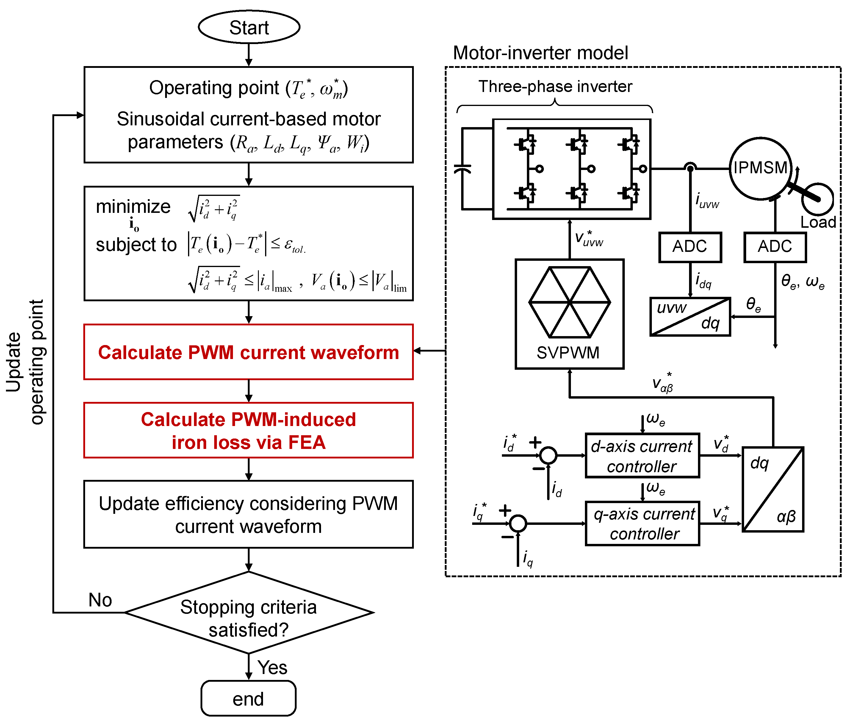
2.1. Procedure for Calculating PWM-Induced Iron Loss

Since the harmonic components of PWM current vary according to the amplitude, phase, and frequency of the reference voltage, the current waveform varies according to the torque and rotational speed of the traction motor. Therefore, unlike the sinusoidal current-based iron loss, which considers only the current vector and fundamental frequency, high-order PWM frequency should be considered in calculating the PWM-induced iron loss. Thus, the time step for FEA needs to become smaller, which leads to an increase in computation cost.
The PWM-induced iron loss can be calculated according to the procedure shown in Figure 1. In order to calculate the PWM current waveform according to the torque and rotational speed, it is necessary to calculate the motor parameters at each operating point. Except for the iron loss, the motor parameters, such as d, q-axis inductance, and flux-linkage, are independent of frequency. Thus, the motor parameters can be predicted by using the sinusoidal current-based motor parameters to perform current vector control of IPMSMs. Then, the characteristics of IPMSMs according to the torque and rotational speed can be calculated to derive the PWM current waveform. The motor-inverter model for calculating the PWM current was implemented using Matlab/Simulink, and the PWM current for each operating point can be derived using the motor parameters. Then, it is possible to calculate the PWM-induced iron loss by applying the PWM current to the electromagnetic FEA model.

2.2. Effect of PWM-Induced Iron Loss on Efficiency of IPMSM

In order to analyze the effect of PWM-induced iron loss, the efficiency of the example IPMSM was analyzed using electromagnetic FEA according to the increases in torque at a constant rotational speed and the increase in rotational speed at constant torque, respectively, as shown in Figure 2a. As the current vector control is performed, the trajectory of the current vector is shown in Figure 2b. When the rotational speed is constant at 2000 rpm, the armature current increases proportionally as the torque increases. On the other hand, as the rotational speed increases at constant torque, the armature current increases, and the current phase angle increases for flux-weakening control.
Figure 3 shows the iron loss and efficiency depending on whether the PWM current is considered according to the electromagnetic torque and rotational speed, respectively. It can be seen that the sinusoidal current-based iron loss and PWM current-based iron loss differ in magnitude due to the PWM-induced iron loss, but they have similar trends for current vector and rotational speed. When the rotational speed increases at constant torque, the iron loss increases as the fundamental frequency of magnetic flux density increases. In addition, the differences in iron loss and efficiency are large depending on the PWM current because of the PWM-induced iron loss. On the other hand, the increase in iron loss as the torque increases is small because the magnetic loading is larger than that of the armature loading in IPMSM. Therefore, the PWM current should be considered to accurately calculate efficiency at the design stage, as the traction motor is mainly operated at high speed rather than high torque.

3. Design Optimization of Traction Motor Using Active Transfer Learning

As we discussed in Section 2, it is necessary to consider the PWM current in the design of the traction motor, but the FEA with a small time step is required for calculating the harmonic magnetic flux density near the PWM frequency band, and it results in an increase in computation cost. In order to reduce the computation cost for efficient optimization, the active transfer learning-based surrogate modeling for PWM iron loss is proposed in this section. In addition, the design process of the traction motor using the proposed method is discussed.

3.1. Formulation of Design Optimization Problem

The detailed design requirements for the traction motor are listed in Table 1. In order to design the high power density traction motor, the rotor topology was selected as V-type with 16 poles and 24 slots, as shown in Figure 4. Since the traction motor is used for personal mobility, the maximum output power is set to 14.5 kW, and the New York City Cycle (NYCC), which is widely used for light-duty vehicles to simulate low-speed urban driving, is used to calculate the energy consumption. The design parameters and their design space are listed in Table 2. The geometry of the traction motor has 8 degrees of freedom (DOF), and global optimization is performed to maximize the overall efficiency through the NYCC drive cycle while minimizing the torque ripple and total harmonic distortion (THD) of the induced voltage. The operating points of the NYCC are compressed into 9 representative operating points, as shown in Figure 5, and weights are set according to the operating frequency. The overall efficiency can be calculated as
η o v e r a l l = n = 1 N η m t , n · w n
where η o v e r a l l and η m t , n are the overall efficiency and the efficiency of the traction motor for the n-th operating point; w n is the weight for the n-th operating point. The torque ripple and THD of the induced voltage can be calculated from the results of electromagnetic FEA as
T r i p p l e = T e , m a x T e , m i n T e , a v g
T H D = n = 2 V a n , r m s 2 V a 1 , r m s 2
where T r i p p l e is the torque ripple; T e , m a x , T e , m i n , and T e , a v g are the maximum, minimum, and average values of electromagnetic torque, respectively; V a n , r m s is the n-th harmonic of induced voltage in rms value.
The overall design process of the traction motor is shown in Figure 6. In the optimization process, DNN is used as a surrogate model for predicting electromagnetic performances such as d and q-axis inductance, flux linkage, iron loss, torque ripple, and THD of induced voltage. Each data point is acquired using electromagnetic FEA, and the collected data is used for training DNNs. The d and q-axis inductance can be derived by using the electromagnetic FEA as
L d = ψ o cos α ψ a i o d , L q = ψ o sin α i o q
where L d , q are d and q-axis inductance; ψ o and ψ a are the flux linkages under load conditions and no-load flux linkage due to field magnets; α is the difference between the no-load flux linkage and the flux linkage under load conditions; i o d , o q are the magnetization d and q-axis currents.
W i = n = 1 V n m = 1 W i , m n B m n , f m
where W i and W i , m n are the total iron loss and iron loss density per n-th element and m-th harmonic, respectively; B n m and f m are magnetic flux density and frequency, respectively; and V n is the volume of the n-th element. All of the performances are analyzed with sinusoidal current, and the DNNs can be trained by using the acquired sinusoidal current-based data with active learning. Therefore, the sinusoidal current-based performances can be predicted by using the trained DNNs, except for iron loss. As the iron loss is affected by PWM current, a DNN for iron loss is additionally trained using the proposed active transfer learning to consider the effect of PWM current. The detailed training process for sinusoidal and PWM current-based performances is described in the next subsection. Then, the multi-objective optimization (MOO) is conducted for designing the traction motor with the NSGA-II algorithm [27]. In order to calculate the overall efficiency, current vector control is conducted for each design point using the predicted sinusoidal current-based d and q-axis inductance, flux linkage, and PWM current-based iron loss. Finally, the optimal solution can be derived by setting the weight of the objective functions of overall efficiency, torque ripple, and THD of induced voltage to 6:2:2.

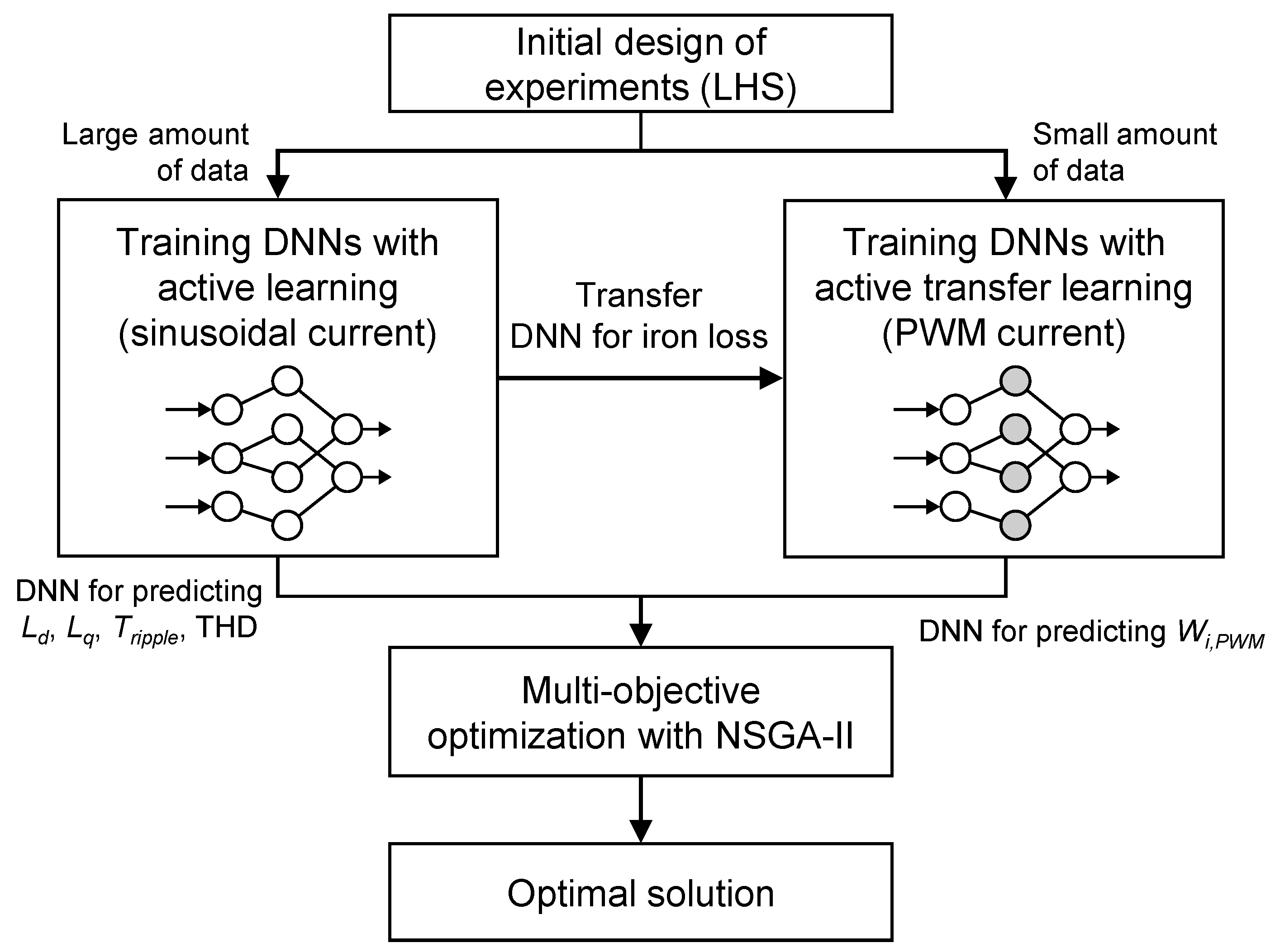
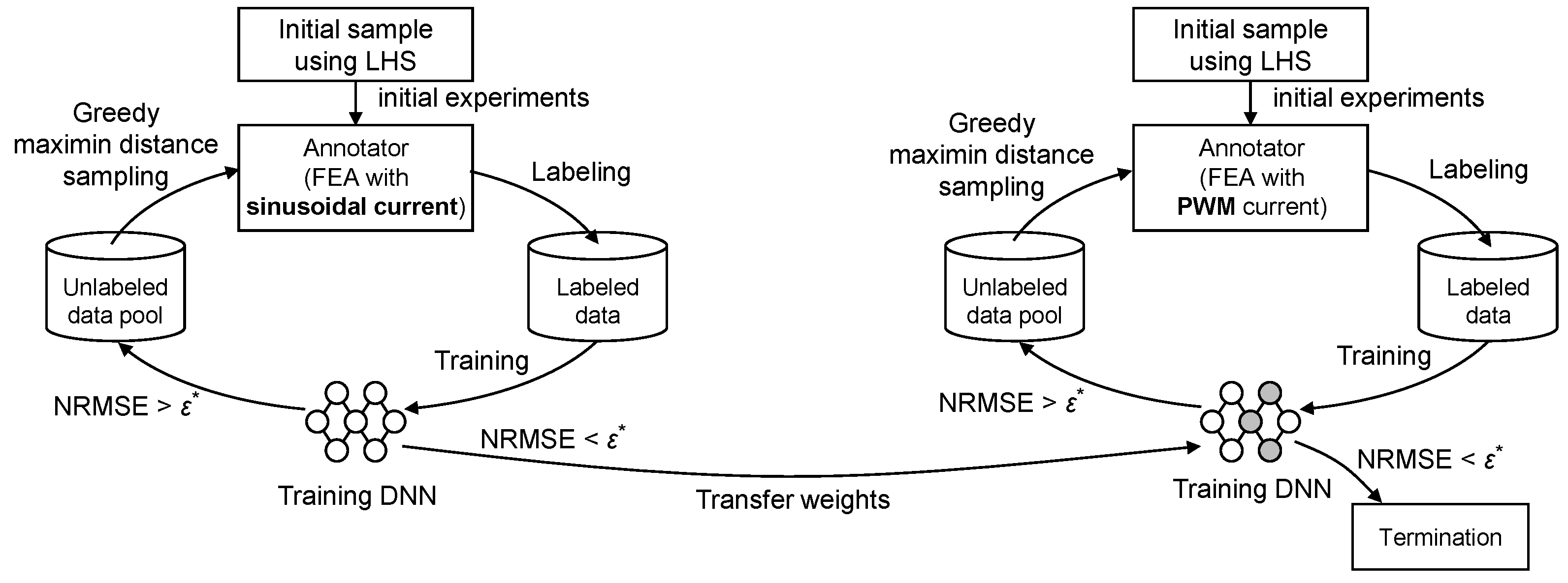
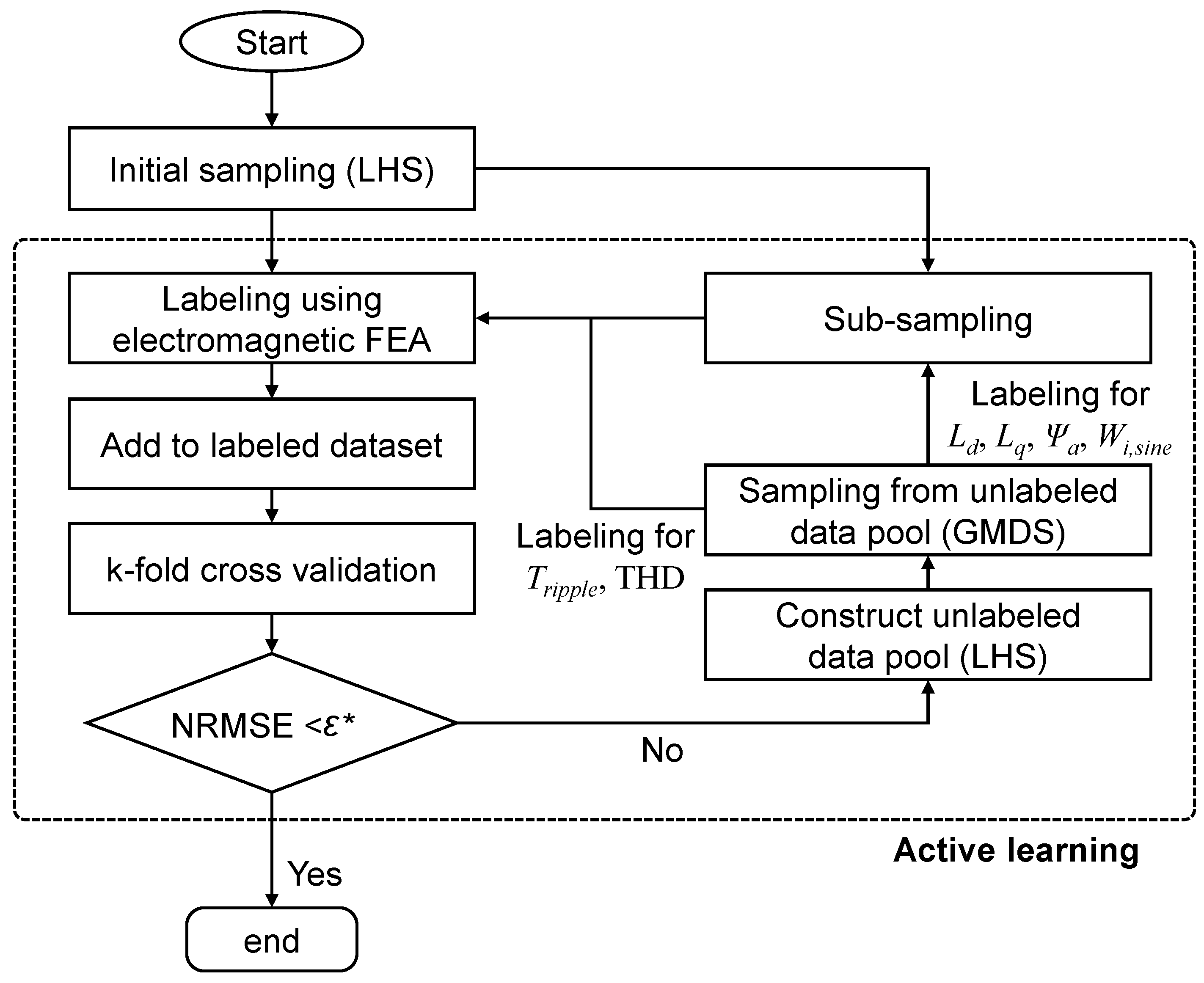
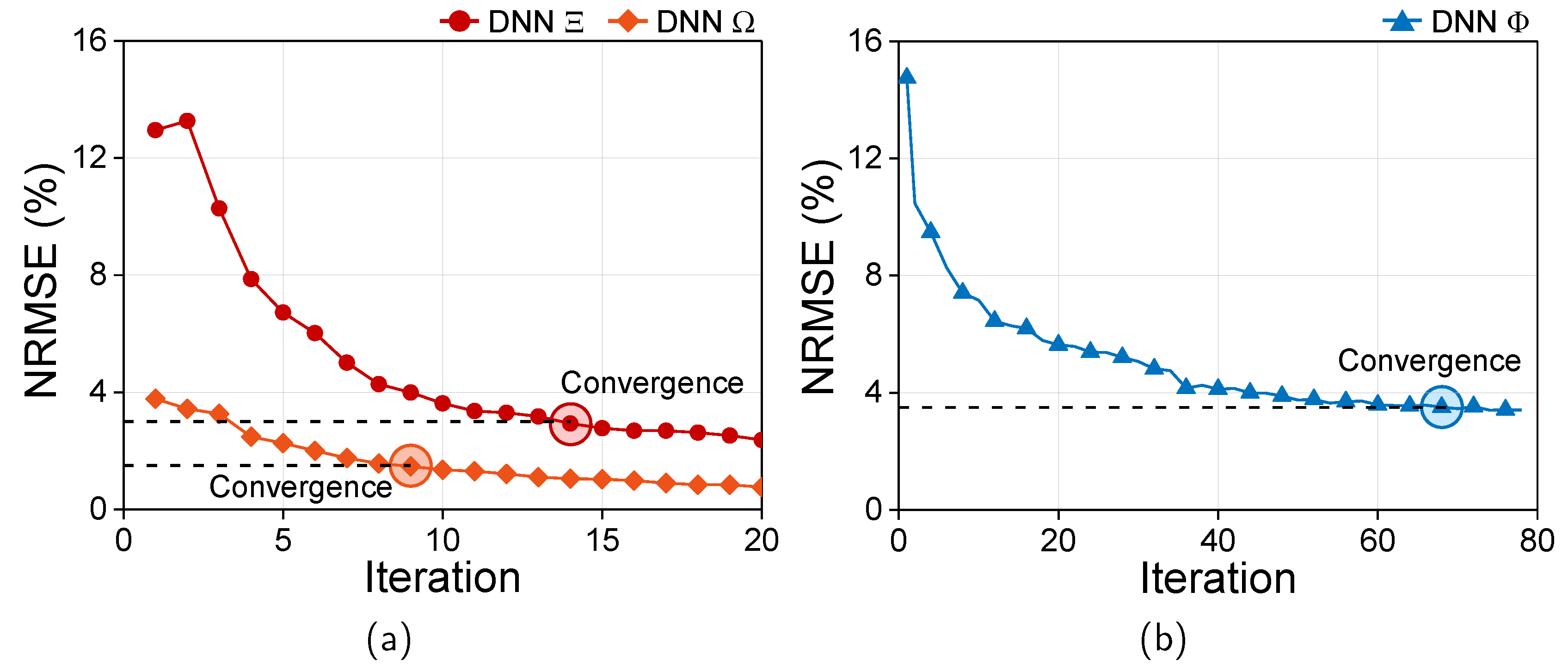
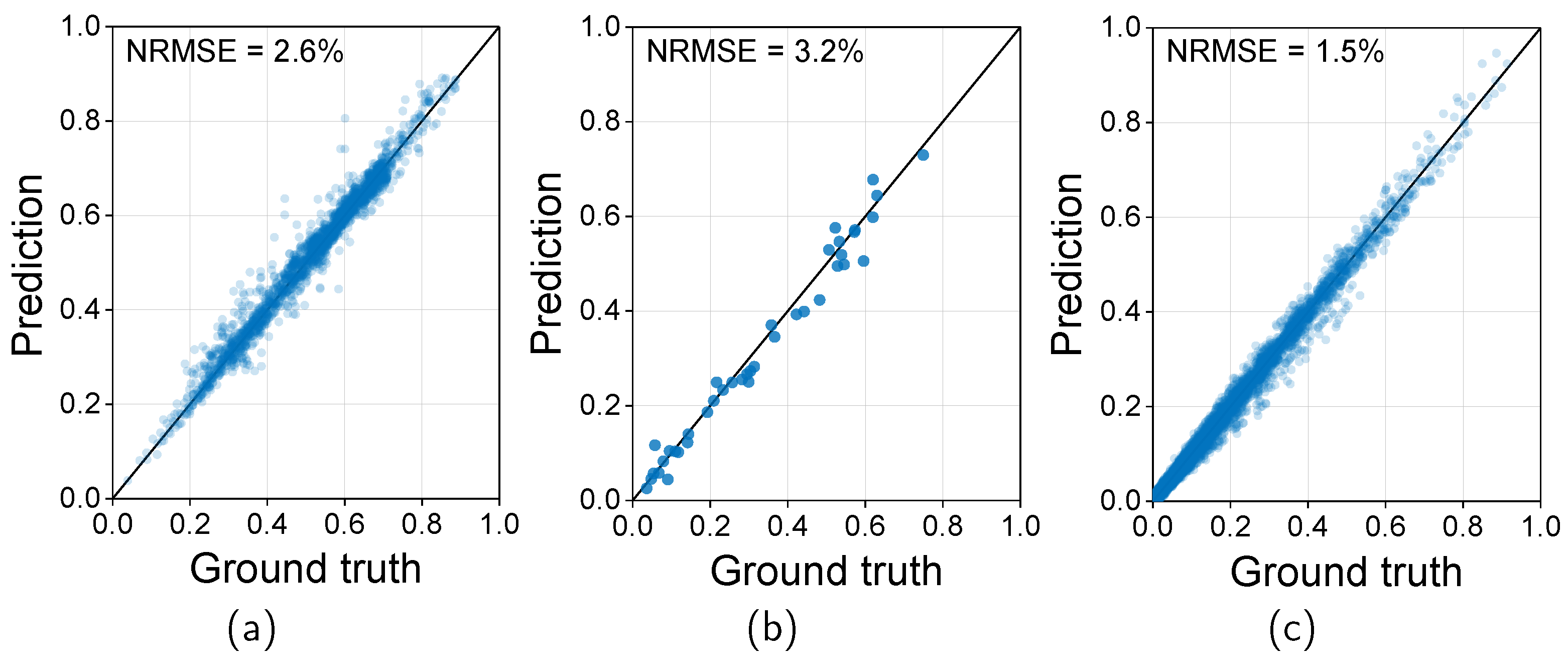
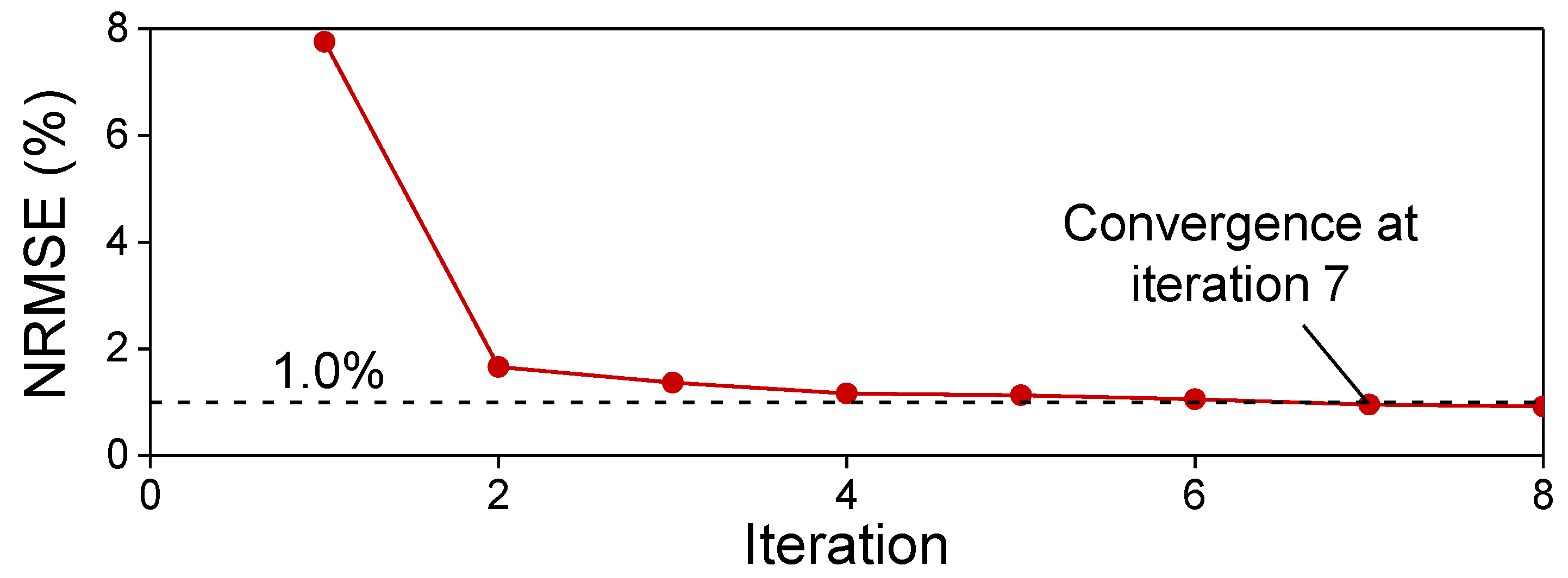
3.2. Training of DNNs for Sinusoidal and PWM Current-Based Motor Performance Using Active Transfer Learning

Figure 7 shows the overall process for training the sinusoidal and PWM current-based motor performance using active transfer learning. The proposed method trains the surrogate model by combining two key methods: active learning and transfer learning. The DNNs for predicting the sinusoidal current-based performance are trained using active learning, and then the DNN for predicting the PWM-induced iron loss is trained using active transfer learning with a small amount of dataset.
Active learning is a training technique in machine learning that efficiently performs the additional labeling process to improve the performance of DNN [28]. The core of active learning is to query the most informative or useful instance among the unlabeled data. In this paper, greedy maximin distance sampling (GMDS) on the input features is used. Assume the unlabeled pool consists of N samples. The goal of GMDS is to select new samples from the unlabeled pool. The selection of a new sample is based on the initial k samples derived using LHS from the unlabeled pool. New samples are selected as the points that maximize the minimum averaged distance from the labeled samples. The average distance between a certain point and the labeled samples can be calculated as follows.
d n m x = x n x m , m = 1 , , k ; n = k + 1 , , N
where d n m x is the distance between the n and m-th samples; Then, the minimum distance from x n to all k labeled samples can be calculated as
d n x = min m d n m x
Figure 8 shows the process for active learning of DNNs for the prediction of sinusoidal current-based motor performance. After the initial sample is extracted using LHS, labeling is performed by electromagnetic FEA. Then, the performance of the DNN is calculated conducting k-fold cross-validation, and additional sampling is conducted by using GMDS when the performance of the DNN does not reach the target. When the accuracy reaches the target, the training of the DNN is terminated.
The most effective way to improve the performance of DNNs is to increase the amount of data. However, it is difficult to increase the amount of data when the cost required for labeling is high. Transfer learning is a method that can effectively train DNNs even when there is not enough data. Transfer learning is a technique that takes domain knowledge from a pre-trained model for the source dataset, D s , and utilizes it to train a new model for the target dataset, D t [24]. In other words, the weights of the pre-trained DNN are used as the initial values of the weights of the target DNN, and the transferred weights are re-optimized to secure the transferred knowledge from the source DNN. The source model can be trained as follows.
f s = arg min f s L s ( f ( X s ) , Y s ) , ( X s , Y s ) D s
where f s is the source model for the source domain; L s is the loss function for the source domain, which is the mean squared error; X s and Y s are the input and label spaces for the source domain. The source dataset has a relatively large size compared to the target dataset because it is relatively easy to obtain labels compared to the target dataset. Therefore, the source DNN is trained to have high regression performance as it is trained to follow the data distribution of the source dataset. Then, the target model can be trained as follows.
f t = arg min f s L t ( f ( X t ) , Y t ) , ( X t , Y t ) D t
where f t is the target model for the source domain; L t is the loss function for the target domain, which is the mean squared error; X t and Y t are the input and label spaces for the target domain.
Table 3 lists the detailed conditions for active learning. In this paper, a multi-layer perceptron is used as the DNN architecture. The hyperparameters for the DNN were tuned as follows: The hidden layer and nodes for each layer were chosen as 4 and 256, and the optimizer was selected as Adam with a learning rate of 1 × 10⁻⁵ [24]. The design variables in Table 2 and the current vector are selected as the input data for DNNs to predict L d , q , ψ a , T r i p p l e , and THD. For the DNN to predict W i , s i n e , the rotational speed is selected as input data in addition to the design variables and current vector because the iron loss is affected by the frequency of magnetic flux density. There are a total of three DNNs: DNN Ξ for predicting L d , q and ψ a , DNN Φ for predicting T r i p p l e and THD, and DNN Ω for predicting W i , s i n e according to the characteristics of performance. In each iteration of active learning, 20 design variable sets are extracted by GMDS, and the current vector and rotational speed are subsampled for each design variable set. Since Ξ and Φ subsample 35 current vectors per iteration, 700 data points are generated during each iteration, and Ω subsamples 9 rotational speeds along with 35 current vectors, resulting in 6300 data points generated during each iteration.
Figure 9a,b shows the results of active learning with GMDS for each DNN. It can be seen that the number of required samples to reach the target NRMSE is different because the data distribution varies according to the labels, and the number of derived data per each iteration differs according to the types of labels. The number of required datasets for DNNs Ξ , Φ , and Ω are 9800, 1400, and 56,700, respectively. In the case of torque ripple and THD, many iterations were required as sub-sampling was not performed. As can be seen in the results, it is possible to minimize the annotation process to achieve target performance by using active learning with GMDS. Figure 10a–c shows the regression performance of DNNs Ξ , Φ , and Ω . Each DNN was trained using all labeled data derived from active learning, and the test dataset was acquired by annotating an additional 20 samples using GMDS. As a result of performing active learning, it can be seen that the NRMSE for all DNNs is within the target performance.
In this paper, active transfer learning is used to reduce the labeling cost for training a DNN to predict PWM-induced iron loss. The trained DNN Ω is used as a source model, and the PWM-induced iron loss according to the same input variables is used as a target dataset for transfer learning. Since a high computation cost is required to obtain PWM-induced iron loss, 10 samples for design variables are selected in each iteration using GMDS, and 35 sub-samples of the current vector and rotational speed for each sample are performed during the active transfer learning. The target accuracy was set to 1.0% because this process involved a much larger computational cost than the training of DNN Ω for predicting the sinusoidal current-based iron loss.
Figure 11 shows the evaluated performance using k-fold cross-validation with active transfer learning for DNN Ω . Contrary to the results for predicting the sinusoidal current-based iron loss, it can be seen that the required target dataset for satisfying the target NRMSE is significantly reduced. In the case of sinusoidal current-based iron loss, 56,700 data points were required to obtain an accuracy of 1.5%, whereas in the case of PWM-induced iron loss, an accuracy of 1.0% can be obtained with only 2450 additional data points by applying active transfer learning. Figure 12a shows the learning curve for DNN Ω with or without using active transfer learning. The validation and test datasets were acquired by annotating an additional 10 samples by using GMDS. As the domain knowledge of the source dataset was utilized when training target DNNs using transfer learning, it can be seen that both NRMSE for the training and validation sets converged to low values. However, in the case of training the DNN from scratch without using transfer learning, it can be seen that the DNN was overfitted as the size of the target dataset was small. Figure 12b shows the comparison between the prediction and ground truth of the test dataset for DNN Ω . As a result of using ATL, it can be seen that the regression performance on the test dataset was highly well evaluated, and as a result of training from scratch without using transfer learning, it can be seen that the regression performance was degraded due to the DNNs being overfitted to the training dataset. In the case of DNN Ω , the results with transfer learning showed higher performance by about 0.6%p compared to the results without transfer learning. Therefore, high regression performance can be achieved efficiently by using ATL with a small dataset.

3.3. Design Results

A multi-objective optimization problem has several objective functions that have a trade-off relationship, so the solution converges on a Pareto front to form a boundary during the optimization process. Therefore, the Pareto front for solving the design problem was searched by using NSGA-II, which is a global optimization algorithm, to maximize the main drive efficiency while minimizing torque ripple and THD of induced voltage. The multi-objective optimization was performed with trained DNN-based surrogate models. The optimal solution was derived by setting the weights of main drive efficiency, torque ripple, and THD of induced voltage to 6:2:2. The predicted main drive efficiency, torque ripple, and THD of induced voltage for the optimal solution 95.9%, 8.2%, 8.2%, 26.9%, 26.9%, respectively. The armature winding was determined by 1.0 mm 1.0 mm copper wire with 45 series turns per phase to produce a target output power within a limited DC voltage.
In order to verify the predicted performances, the electromagnetic FEA for the optimized IPMSM was conducted. Figure 13a–c shows the predicted and simulated results of d and q-axis inductance and flux linkage, respectively. As the surrogate model was well trained, the NRMSE between predicted and simulated results was 0.91%, 0.80%, and 0.56%, respectively. As a result, the predicted main drive efficiency was 95.9%, and the simulated result was 95.3%, with an error of 0.6%p between each result.
The proposed method has been successfully applied to a 14.5 kW traction motor for small EVs and can be extended to electric machines of any size. Given that most electric machines operate with PWM supply, this approach can significantly reduce EV development time by addressing PWM-induced iron loss efficiently.

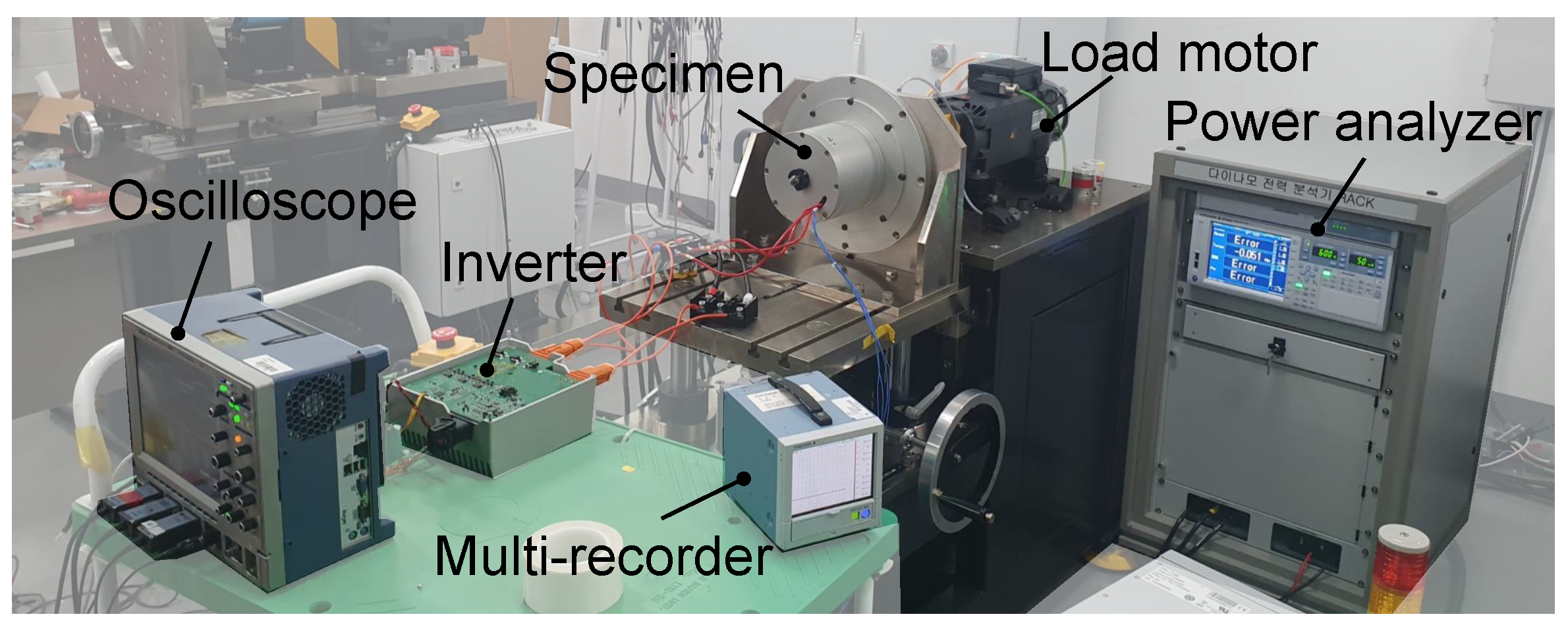
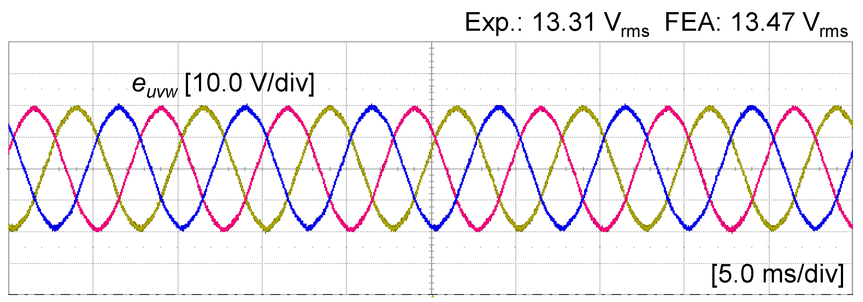
4. Experimental Verification

Figure 14 shows the experimental setup with the fabricated motor. In order to verify the performance of the magnetic circuit for the fabricated motor and the efficiency accounting for the PWM-induced iron loss, a dynamometer with measuring equipment is necessary. Therefore, a dynamometer and inverter were used to control the specimen with various output powers. The dynamometer consists of a load motor with Siemens 1PH8087-1SN00-0LA1 and Kistler 4503B, allowing it to operate up to 15 kW and 200 Nm. The Unidrive M700 of Control Techniques was used as an inverter to drive the fabricated motor, and the maximum current is 70 Arms. The GP20 of Yokogawa was used as a multi-recorder for monitoring the temperature variation of the windings. In addition, a power meter of Yokogawa WT1800 was used for measuring the input and output power of the fabricated motor, and an oscilloscope was used to measure the waveform of the phase current and line-to-line voltage. Figure 15 shows the comparison between the simulated and measured waveforms of the phase back-EMF at 1000 rpm at room temperature. Since the difference in the back-EMF between the simulated and test results was 1.2%, the specimen was properly fabricated according to the design result.
In order to verify the predicted efficiency of the optimized traction motor, a load test was conducted at 2100 rpm through 4100 rpm at 12.5 Nm, which are the main operating points. The experiments were conducted after a state of 30 minutes of continuous driving for temperature equilibrium to exclude the influence of parameter uncertainty. The measured efficiency was compared with the predicted efficiency and simulation results calculated by FEA. The predicted efficiency was calculated using electromagnetic loss predicted from the DNN surrogate model and FEA under each load condition, as well as the predicted mechanical loss from the no-load test. The efficiency was evaluated by considering iron loss with PWM current, and the eddy current loss of the PM was neglected because the PMs were segmented into small pieces. Figure 16 shows the comparison of power loss and efficiency for measured and predicted results. The efficiency predicted using the proposed method differed by up to 0.3%p from the efficiency calculated using FEA. Therefore, it has been demonstrated that the proposed method can be used for the prediction of efficiency instead of using FEA. Consequently, the calculated efficiency using the proposed method was verified, and the reliability of the design optimization could be secured.

5. Conclusions

In this paper, a computationally efficient design process for traction motors considering PWM-induced iron loss is proposed. As the calculation of iron loss considering PWM current requires a high computational cost, an active transfer learning-based training process for the DNN surrogate model is proposed for design optimization. The proposed method consists of transfer learning to reduce computation costs and active learning to achieve target accuracy. The transfer learning process can be achieved by using a large amount of sinusoidal current-based iron loss data and a small amount of PWM-induced iron loss data; thus, an accurate surrogate model for predicting PWM-induced iron loss can be trained efficiently. After training the surrogate model, the design optimization was performed using NSGA-II, which is a global multi-objective optimization algorithm, to maximize the drive efficiency of electric vehicles while minimizing the torque ripple and THD of induced voltage. To verify the design results, no-load and load tests were conducted. As a result of the load test, the error between the measured and simulated efficiency was up to 0.3%. Therefore, the validity of the trained surrogate model was verified. Unlike internal combustion engine vehicles, EVs benefit from shortened development cycles due to the standardization of e-powertrains. To align with this trend, active transfer learning has been proposed to further reduce the development time of traction motors. By applying this method, it is expected that the cost required for traction motor design can be reduced, and by utilizing the secured cost, the element technology required for the development of a high-efficiency traction motor can be secured, contributing to energy savings.

Author Contributions

Conceptualization, S.-H.P.; methodology, S.-H.P.; software, S.-H.P.; validation, M.-S.L.; resources, M.-S.L.; data curation, S.-H.P.; writing—original draft preparation, S.-H.P.; writing—review and editing, M.-S.L. and S.-H.P.; visualization, S.-H.P.; supervision, M.-S.L.; project administration, M.-S.L.; funding acquisition, M.-S.L. All authors have read and agreed to the published version of the manuscript.

Funding

This research received no external funding.

Data Availability Statement

The original contributions presented in this study are included in the article. Further inquiries can be directed to the corresponding author.

Conflicts of Interest

The authors declare no conflicts of interest.

References

  1. Krings, A.; Monissen, C. Review and Trends in Electric Traction Motors for Battery Electric and Hybrid Vehicles. In Proceedings of the 2020 International Conference on Electrical Machines (ICEM), Gothenburg, Sweden, 23–26 August 2020; pp. 1807–1813. [Google Scholar]
  2. Yang, Y.; Castano, S.M.; Yang, R.; Kasprzak, M.; Bilgin, B.; Sathyan, A.; Dadkhah, H.; Emadi, A. Design and Comparison of Interior Permanent Magnet Motor Topologies for Traction Applications. IEEE Trans. Transp. Electrif. 2017, 3, 86–97. [Google Scholar] [CrossRef]
  3. Husain, I.; Ozpineci, B.; Islam, M.S.; Gurpinar, E.; Su, G.J.; Yu, W.; Chowdhury, S.; Xue, L.; Rahman, D.; Sahu, R. Electric Drive Technology Trends, Challenges, and Opportunities for Future Electric Vehicles. Proc. IEEE 2021, 109, 1039–1059. [Google Scholar] [CrossRef]
  4. Park, S.H.; Lee, E.C.; Park, J.C.; Hwang, S.W.; Lim, M.S. Prediction of Mechanical Loss for High-Power-Density PMSM Considering Eddy Current Loss of PMs and Conductors. IEEE Trans. Magn. 2021, 57, 1–5. [Google Scholar] [CrossRef]
  5. Fischer, M.; Werber, M.; Schwartz, P.V. Batteries: Higher Energy Density Than Gasoline? Energy Policy 2009, 37, 2639–2641. [Google Scholar] [CrossRef]
  6. Liu, Y.; Liao, Y.G.; Lai, M.C. Effects of Battery Pack Capacity on Fuel Economy of Hybrid Electric Vehicles. In Proceedings of the 2021 IEEE Transportation Electrification Conference & Expo (ITEC), Brasov, Romania, 25–28 September 2022; IEEE: Piscataway, NJ, USA, 2021; pp. 771–775. [Google Scholar]
  7. Zhou, S.; Chen, Z.; Huang, D.; Lin, T. Model Prediction and Rule Based Energy Management Strategy for a Plug-In Hybrid Electric Vehicle with Hybrid Energy Storage System. IEEE Trans. Power Electron. 2021, 36, 5926–5940. [Google Scholar] [CrossRef]
  8. Shao, L.; Karci, A.E.H.; Tavernini, D.; Sorniotti, A.; Cheng, M. Design Approaches and Control Strategies for Energy-Efficient Electric Machines for Electric Vehicles—A Review. IEEE Access 2020, 8, 116900–116913. [Google Scholar] [CrossRef]
  9. Lee, J.D.; Park, D.H.; Kim, R.Y. Novel Variable Switching Frequency PWM Strategy for a SiC-MOSFET-Based Electric Vehicle Inverter to Increase Battery Usage Time. IEEE Access 2022, 10, 21929–21940. [Google Scholar] [CrossRef]
  10. Xue, S.; Feng, J.; Guo, S.; Chen, Z.; Peng, J.; Chu, W.; Xu, P.; Zhu, Z. Iron loss model for electrical machine fed by low switching frequency inverter. IEEE Trans. Magn. 2017, 53, 1–4. [Google Scholar] [CrossRef]
  11. Zhu, S.; Shi, B. Modeling of PWM-induced iron losses with frequency-domain methods and low-frequency parameters. IEEE Trans. Ind. Electron. 2022, 69, 2402–2413. [Google Scholar] [CrossRef]
  12. Ahn, D.G.; Yoon, M.H.; Hong, J.P.; Jung, J.W. Finite-Element Analysis of Local Flux Density Variation Considering PWM Current Harmonics. IEEE Trans. Magn. 2018, 54, 8201804. [Google Scholar] [CrossRef]
  13. Jeong, T.C.; Kim, W.H.; Kim, M.J.; Lee, K.D.; Lee, J.J.; Han, J.H.; Sung, T.H.; Kim, H.J.; Lee, J. Current Harmonics Loss Analysis of 150-kW Traction Interior Permanent Magnet Synchronous Motor Through Co-Analysis of d, q-Axis Current Control and Finite Element Method. IEEE Trans. Magn. 2013, 49, 2343–2346. [Google Scholar] [CrossRef]
  14. Akatsu, K.; Narita, K.; Sakashita, Y.; Yamada, T. Impact of Flux Weakening Current to the Iron Loss in an IPMSM Including PWM Carrier Effect. In Proceedings of the 2009 IEEE Energy Conversion Congress and Exposition (ECCE), San Jose, CA, USA, 20–24 September 2009; IEEE: Piscataway, NJ, USA, 2009; pp. 1927–1932. [Google Scholar]
  15. Yamazaki, K.; Abe, A. Loss Investigation of Interior Permanent-Magnet Motors Considering Carrier Harmonics and Magnet Eddy Currents. IEEE Trans. Ind. Appl. 2009, 45, 659–665. [Google Scholar] [CrossRef]
  16. Sarigiannidis, A.G.; Kladas, A.G. Switching Frequency Impact on Permanent Magnet Motors Drive System for Electric Actuation Applications. IEEE Trans. Magn. 2015, 51, 1–4. [Google Scholar] [CrossRef]
  17. Park, S.H.; Chin, J.W.; Cha, K.S.; Ryu, J.Y.; Lim, M.S. Investigation of AC Copper Loss Considering Effect of Field and Armature Excitation on IPMSM with Hairpin Winding. IEEE Trans. Ind. Electron. 2023, 70, 12102–12112. [Google Scholar] [CrossRef]
  18. Yamazaki, K.; Seto, Y. Iron Loss Analysis of Interior Permanent-Magnet Synchronous Motors-Variation of Main Loss Factors due to Driving Condition. IEEE Trans. Ind. Appl. 2006, 42, 1045–1052. [Google Scholar] [CrossRef]
  19. Cheong, B.; Giangrande, P.; Zhang, X.; Galea, M.; Zanchetta, P.; Wheeler, P. Evolutionary Multiobjective Optimization of a System-Level Motor Drive Design. IEEE Trans. Ind. Appl. 2020, 56, 6904–6913. [Google Scholar] [CrossRef]
  20. Godbehere, J.; Popescu, M.; Michon, M. Optimization of an IPM Traction Motor Considering the Electric Drive Unit System Requirements. In Proceedings of the 2021 IEEE Energy Conversion Congress and Exposition (ECCE), Vancouver, BC, Canada, 10–14 October 2021; IEEE: Piscataway, NJ, USA, 2021; pp. 3667–3674. [Google Scholar]
  21. Duan, Y.; Ionel, D.M. A Review of Recent Developments in Electrical Machine Design Optimization Methods with a Permanent-Magnet Synchronous Motor Benchmark Study. IEEE Trans. Ind. Appl. 2013, 49, 1268–1275. [Google Scholar] [CrossRef]
  22. Li, S.; Zhang, S.; Habetler, T.G.; Harley, R.G. Modeling, Design Optimization, and Applications of Switched Reluctance Machines—A Review. IEEE Trans. Ind. Appl. 2019, 55, 2660–2681. [Google Scholar] [CrossRef]
  23. Shimizu, Y.; Morimoto, S.; Sanada, M.; Inoue, Y. Investigation of Irreversible Demagnetization Constraints in Magnet Volume Minimization Design of IPMSM for Automotive Applications Using Machine Learning. In Proceedings of the 2021 IEEE International Electric Machines & Drives Conference (IEMDC), Hartford, CT, USA, 17–20 May 2021; IEEE: Piscataway, NJ, USA, 2021; pp. 1–6. [Google Scholar]
  24. Park, S.H.; Chin, J.W.; Cha, K.S.; Lim, M.S. Deep Transfer Learning-Based Sizing Method of Permanent Magnet Synchronous Motors Considering Axial Leakage Flux. IEEE Trans. Magn. 2022, 58, 1–5. [Google Scholar] [CrossRef]
  25. Barmada, S.; Fontana, N.; Sani, L.; Thomopulos, D.; Tucci, M. Deep Learning and Reduced Models for Fast Optimization in Electromagnetics. IEEE Trans. Magn. 2020, 56, 1–4. [Google Scholar] [CrossRef]
  26. Ibrahim, I.; Silva, R.; Mohammadi, M.H.; Ghorbanian, V.; Lowther, D.A. Surrogate Models for Design and Optimization of Inverter-Fed Synchronous Motor Drives. IEEE Trans. Magn. 2021, 57, 1–5. [Google Scholar] [CrossRef]
  27. Blank, J.; Deb, K. pymoo: Multi-Objective Optimization in Python. IEEE Access 2020, 8, 89497–89509. [Google Scholar] [CrossRef]
  28. Wu, D.; Lin, C.T.; Huang, J. Active learning for regression using greedy sampling. Inf. Sci. 2019, 474, 90–105. [Google Scholar] [CrossRef]
Figure 1. Process for calculating efficiency map of IPMSM considering PWM-induced iron loss.
Mathematics 13 00915 g001
Figure 2. Current vector trajectory according to the electromagnetic torque or rotational speed of example IPMSM: (a) operating points and (b) corresponding current vector trajectory.
Mathematics 13 00915 g002
Figure 3. Iron loss and efficiency depending on whether the PWM current is considered according to the electromagnetic torque and rotational speed.
Mathematics 13 00915 g003
Figure 4. Configuration of the 16-poles and 24-slots example IPMSM.
Mathematics 13 00915 g004
Figure 5. NYCC driving cycle and main operating points of traction motor.
Mathematics 13 00915 g005
Figure 6. Detailed design process of IPMSM for EV traction considering PWM-induced iron loss using active transfer learning with multi-objective optimization.
Mathematics 13 00915 g006
Figure 7. Active transfer learning-based training of DNNs to reduce computational cost.
Mathematics 13 00915 g007
Figure 8. Active learning process of DNNs for predicting sinusoidal current-based motor performance.
Mathematics 13 00915 g008
Figure 9. Results of active learning for (a) DNN Ξ and Ω , (b) DNN Φ .
Mathematics 13 00915 g009
Figure 10. Regression performance for (a) DNN Ξ , (b) DNN Φ , (c) DNN Ω .
Mathematics 13 00915 g010
Figure 11. Results of training PWM-induced iron loss using active transfer learning: Converged point with learning curve.
Mathematics 13 00915 g011
Figure 12. Comparison of training performance between DNN Ω with or without using active transfer leraning: (a) learning curve and (b) regression performance.
Mathematics 13 00915 g012
Figure 13. Comparison of simulated and predicted motor parameters: (a) d-axis inductance, (b) q-axis inductance, and (c) flux-linkage.
Mathematics 13 00915 g013
Figure 14. Fabricated specimen consists of experimental setup for no-load and load test.
Mathematics 13 00915 g014
Figure 15. Comparison between measured and calculated no-load back-EMF of specimen.
Mathematics 13 00915 g015
Figure 16. Comparison of loss and efficiency between measured and simulated results at each operating point.
Mathematics 13 00915 g016
Table 1. Design requirements for 14.5 kW personal mobility traction system.
ItemUnitValue
Number of poles-16
Number of slots-24
Nominal battery voltageV144
Max. output powerkW14.5
Peak torqueNm45
Max. speedrpm7000
Max. current deisntyArms/mm215.0
Switching frequencykHz12
Operating temperature°C50
Drag coefficient-0.64
Frontal aream21.59
Vehicle weightkg690
Drive cycle-NYCC
Table 2. Design space for optimizing traction motor.
Design VariablesUnitMin.Max.
Slot areamm275.0100.0
Slot openmm1.04.0
Tooth tipmm0.51.2
Split ratio-0.650.75
PM thicknessmm2.03.5
Pole arcdeg.7.59.0
PM angledeg.38.085.0
Rotor eccentricitymm9.833.5
Table 3. Conditions and settings for active learning with sinusoidal current-based performance.
ItemDNN Ξ DNN Φ DNN Ω
Output L d , q , ψ a T r i p p l e , THD W i , s i n e
Target accuracy3.0%3.5%1.5%
No. of samples for each iteration202020
No. of subsamples for each iteration35-315
Total no. of data for each iteration700206300
No. of hidden layers444
No. of hidden units256256256
Disclaimer/Publisher’s Note: The statements, opinions and data contained in all publications are solely those of the individual author(s) and contributor(s) and not of MDPI and/or the editor(s). MDPI and/or the editor(s) disclaim responsibility for any injury to people or property resulting from any ideas, methods, instructions or products referred to in the content.

