Abstract
During the last five years, spiking neural P (SN P) systems have attracted a lot of attention in the field of cryptography since these systems can more efficiently support advanced and complex cryptographic algorithms due to their high computational capabilities. Specifically, these systems can be seen as a potential solution to efficiently performing asymmetric algorithms, which are more demanding than symmetric systems. This factor becomes critical, especially in resource-constrained single-board computer systems, since many of these systems are currently used to ensure the security of IoT applications in portable systems. In this work, we present for the first time the implementation of an asymmetric encryption algorithm called ElGamal based on spiking neural P systems and their cutting-edge variants. The proposed design involves the encryption and decryption processes. Specifically, we propose the design of a neural network to efficiently perform the extended Euclidean algorithm used in the decryption task. Here, we exert major efforts to create a compact and high-performance circuit to perform the extended Euclidean algorithm since the calculation of this algorithm is the most demanding when the decryption process is required. Finally, we perform several tests to show the computational capabilities of our proposal in comparison to conventional implementations on single-board computer systems. Our results show that the proposed encryption/decryption scheme potentially allows its use to ensure confidentiality, data integrity, and secure authentication, among other applications for resource-constrained embedded systems.
MSC:
68T07; 68T01
1. Introduction
In the last five years, spiking neural P systems have attracted significant attention as a cutting-edge solution within cybersecurity. These systems take advantage of the unique properties of spiking neurons, characterized by their discrete signaling mechanisms, making them suitable for practical hardware implementations. Recent studies have explored the application of spiking neural P systems within mobile operating systems, focusing on addressing critical issues such as phishing and spam detection [1]. The findings of these experiments reveal an impressive accuracy rate that surpasses 90%, underscoring the effectiveness of this innovative approach in strengthening security protocols and protecting users against malicious online threats. In addition, other works have been developed to create key-agreement protocols based on spiking neural networks with anti-spikes. Specifically, the authors created an advanced system inspired by the functionality of the tree parity machine [2]. More specifically, recent studies have shown that spiking neural P systems can be used to compute the RSA algorithm [3], which is one of the most used algorithms to secure communications over the Internet, securing the exchange of sensitive information, such as in emails and messaging applications. However, the implementation of this algorithm requires large area consumption and processing time. In particular, the calculation of the modular exponentiation is computationally demanding [4]. On the other hand, the Elgammal encryption algorithm can be seen as a potential solution to guarantee more security compared to the RSA algorithm. However, ElGamal requires more processing time than the RSA algorithm. Therefore, the use of spiking neural P systems to support the ElGamal opens new horizons in the simulation of advanced public-key cryptographic algorithms since the SN P systems are considered parallel and distributed computing systems. Recently, several variants of SN P systems, such as anti-spikes [5,6,7], astrocytes [8], weights in synapses [9,10,11], rules in synapses [12,13,14], asynchronous mechanisms [15], cooperative rules [16], programming synaptic connections between neurons [17], and communication on request [18], have been proposed to increase the computational capabilities of the conventional SN P systems. Here, we have made great efforts to design neural circuits to support the ElGamal cryptographic algorithm based on the SNQ P systems. Additionally, we use spiking neural P systems with communication on request (SNQ P) to design the Extended Euclidean Algorithm, which is a necessary method for calculating the multiplicative inverse of an integer in the decryption process of the ElGamal encryption algorithm. In addition, we incorporate delays in synapses to improve communication mechanisms between neurons. To verify the validity of our design, we conducted various encryption and decryption tests on different texts.
2. The Proposed Implementation of the ElGamal Encryption/Decryption Scheme Based on SNQ P Systems
Before presenting the proposed ElGamal encryption/decryption scheme based on SNQ P Systems, we provide some concepts and necessary notations related to the formal definition of the SN P systems with communication on request. In general terms, the SN P systems are mainly composed of neurons interconnected through synapses. Specifically, the behavior of the soma is regulated by rules forgetting rule and firing rule) to process information, which is encoded by means of spikes [19]. The definition of SNQ P systems provided in [18] allows for the handling of different types of spikes; however, in this work, we only use one type of spike. Therefore, the following definition is based on [20].
Definition 1.
A spiking neural P system with communications on request (SNQ P System) is a tuple consisting of four components: a finite alphabet, neurons, synapses, and an output neuron. The system is mathematically defined as follows:
where
- is the number of neurons;
- , where a is the unique element of this set called a spike;
- represents the set of neurons where , and the following applies:
- -
- is the number of spikes present in neuron in the initial configuration of the system;
- -
- is a finite set of rules in neuron , with syntax ; here, E is a regular expression over a and λ (the empty string), and w is a finite non-empty sequence of queries of the form or , where , , and . t is the delay time for rule to be applied.
- is the set of synapses. Let s be an element of . Then, s has the form , where the pair represents the synaptic connection between and , with and . The term w indicates that, if c spikes are required by the receiving neuron, only spikes will reach it . When the weight , we use the notation instead of .
- denotes the output neuron.
Now, we explain the meaning of the queries and . If neuron contains , then neuron requests p copies of a from neuron . If neuron contains , then neuron requests all spikes from neuron . Note that these types of queries implicitly define the set of synapses. To apply the rule in neuron two firing conditions must be satisfied: (1) (the number of spikes contained in must be in E. (2) The neuron must contain at least p spikes of type a. Suppose two or more requesting neurons want to simultaneously apply the rule , and the two firing conditions are satisfied. In that case, only p copies of spike a are removed from the emitting neuron , and these p spikes are replicated and transmitted simultaneously to each of the requesting neurons. There are conflicting queries when two or more neurons require a different number of spikes from a sending neuron. In such cases, the conflict is resolved by selecting one of the queries in a non-deterministic manner and discarding the rest. A spiking neural P system with communication on request starts from its initial configuration, which is defined by the number of spikes present in each neuron, and proceeds by applying the rules described above in all neurons to obtain the next configuration, which is called a transition. A sequence of transitions from one configuration to another is called a computation. A computation halts if no rule can be applied in any neuron. The result of an SNQ P system is the number of spikes present in in the halting configuration. Although our definition of SNQ P systems incorporates the concept of time delay in rules, it is still equivalent to Turing machines. If we consider a zero delay in all neurons, our definition becomes equivalent to those in [18,20], which are computationally universal.
Recently, the use of spiking neural P systems with communication on request (SNQ P systems) has increased the computational capabilities of arithmetic neural circuits by exploiting their parallel processing capabilities in natural computing due to the ability of a neuron to request any number of spikes from another simultaneously. Based on this, we use SNQ P systems to support the ElGamal encryption/decryption scheme since this algorithm is the most demanding circuit in terms of processing speed.
The ElGamal encryption/decryption scheme includes three steps:
- The calculation of the modular exponentiation operation, defined by the operation , where q is a prime number, is a primitive root of q, is the value of the private key used in the ElGamal encryption algorithm, and the public key is composed as follows: .
- For encryption-process operations, we need to calculate three operations, , and , where p is a random number defined by the system, and M is the plain text; both values must be less than q.
- For decryption process operations, , calculate the inverse modular product and .
2.1. Modular Exponentiation
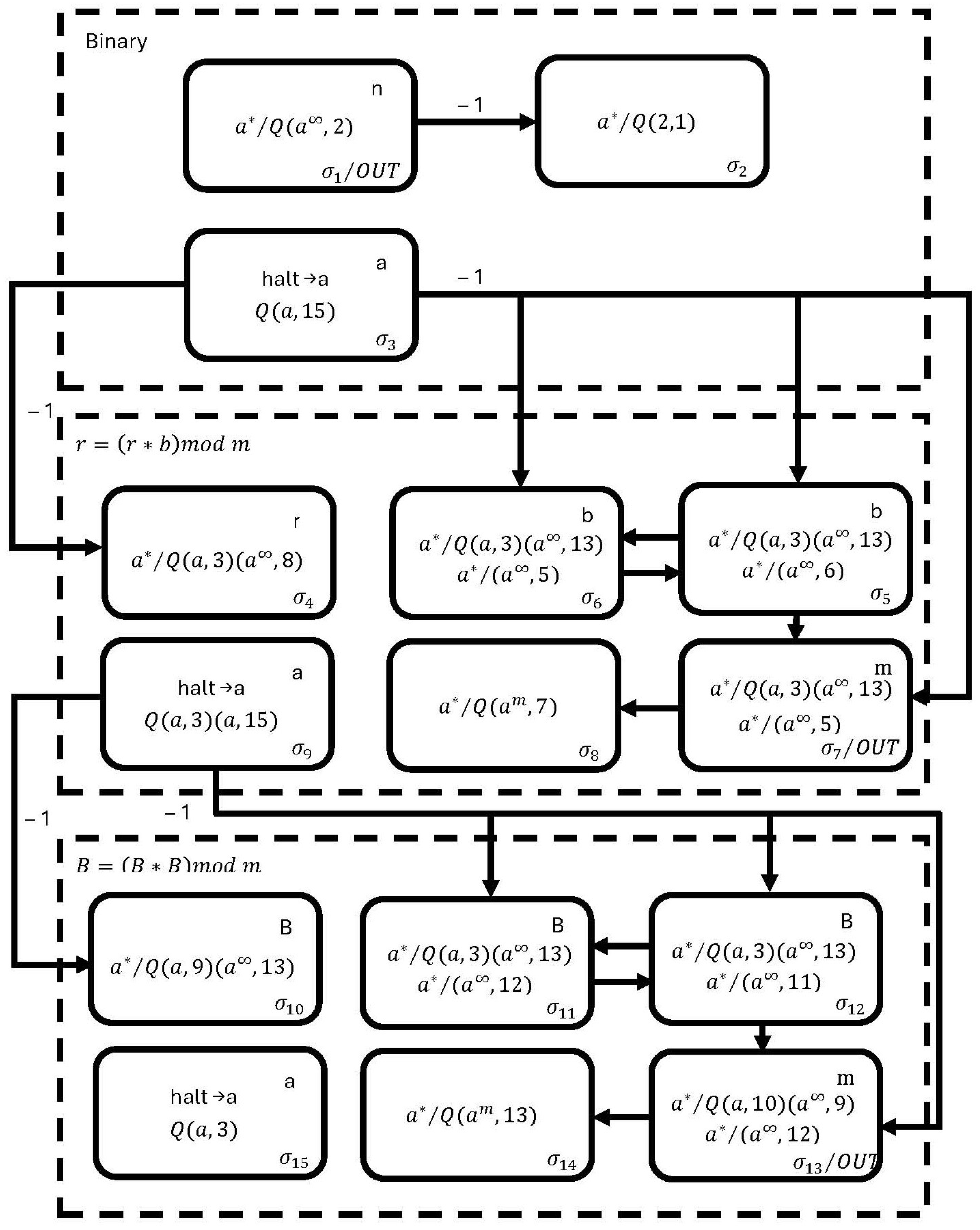
To design the proposed neural modular exponentiation circuit, we use the fast modular exponentiation algorithm; in our design, we use fifteen neurons, , , , , , , , , , , , , , , and , to perform the operation , as shown in Figure 1.

Figure 1.
The proposed membrane in SNQ P systems for performing modular exponentiation .
The circuit operates as follows. In the first simulation step, neuron is loaded with the exponentiation value, neurons and are loaded with (also known as B), and neurons and are loaded with q (also known as m). Neuron computes the binary representation of . Once the binary membrane reaches the halting condition, the membrane executes the operation . In this process, neurons and ensure the execution of , storing the result in neuron . Neuron computes the modulo operation, and neuron fires a spike when the binary membrane reaches de halting condition.
The values in neurons and are then overwritten with the result stored in . Finally, the membrane follows a similar process, with the only difference being that, instead of computing , it calculates . The result is stored in neuron . Ultimately, the final result of is obtained in neuron .
According to the formal definition of SNQ P systems, the proposed neural modular exponentiation circuit is mathematically expressed as follows.
where
2.2. The Proposed Implementation of the ElGamal Encryption Process Based on SNQ P Systems
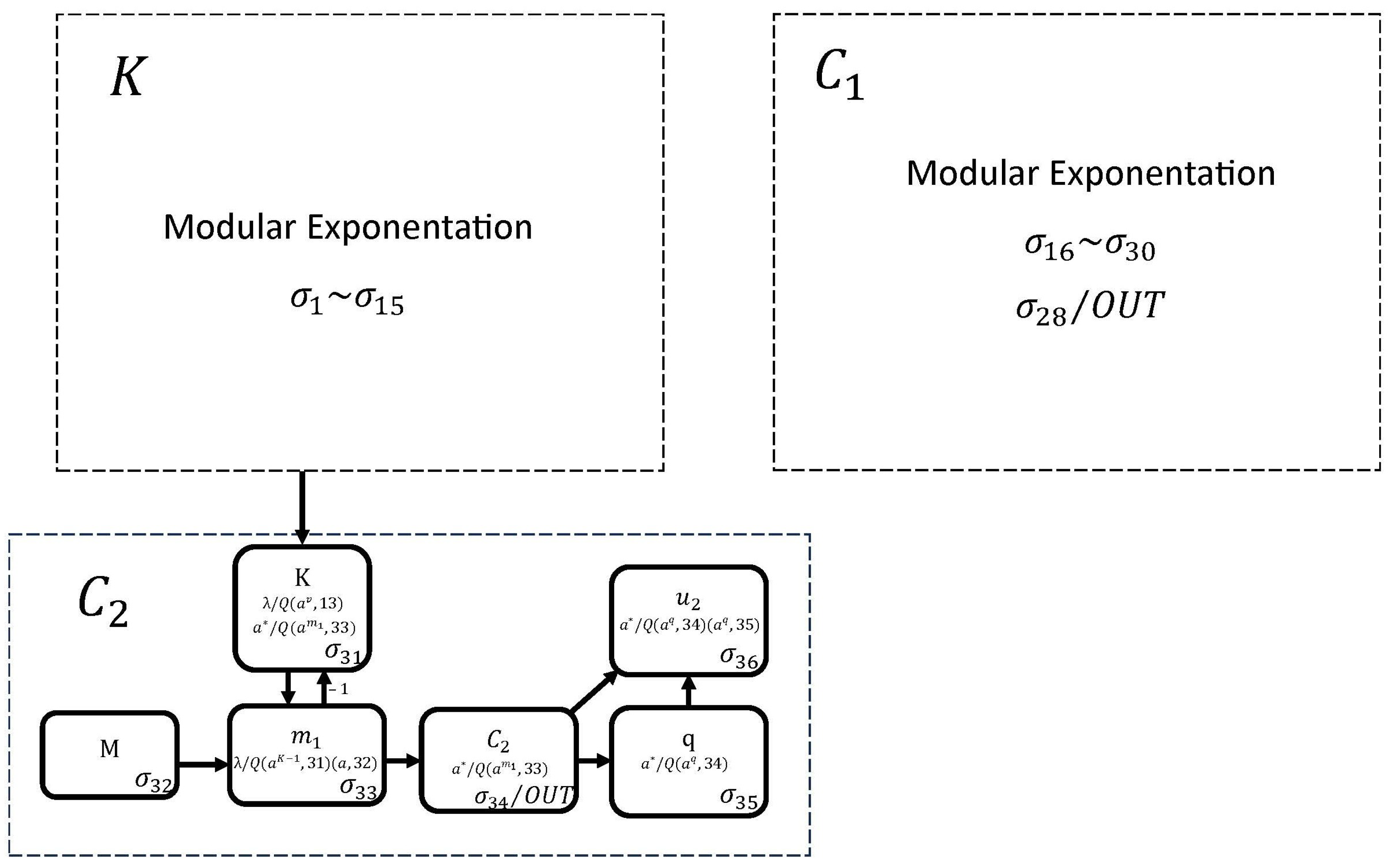
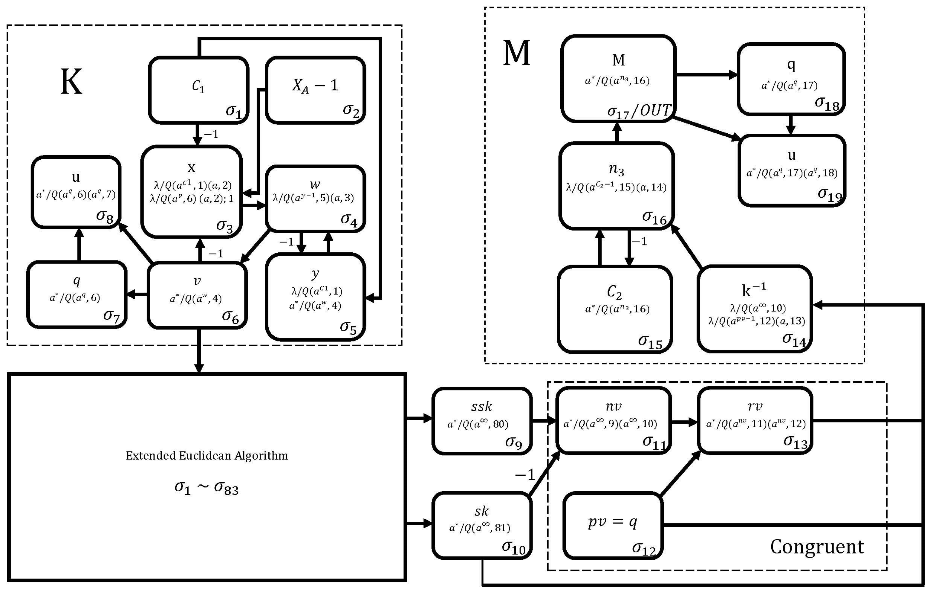
To design the proposed neural encryption circuit, we use 22 neurons, as shown in Figure 2. The K module performs the operation and consists of neurons , , , , , , , and . The module performs the operation and is composed of neurons , , , , , , , and . Finally, neurons , , , , , and perform the operation in the module.

Figure 2.
The proposed neural encryption circuit.
This circuit works as follows. At the first simulation step, neurons , , and are loaded with , and M, respectively, while neurons and are loaded with , and neurons , , and are loaded with the q value. We can observe, in this circuit, that modules K and perform the modular exponentiation whose operation has already been described in Figure 1, so it only remains to describe the operation of the module.
Module starts its operation when no rule can be applied to any neuron in module K. At this point, spikes are loaded into neuron . In the next simulation step, neuron is loaded with K spikes (it receives from neuron and 1 from neuron ). This process is repeated M times until is obtained in neuron . Finally, neurons and perform the modular operation to obtain the final result of in neuron .
According to the formal definition of SNQ P systems, the proposed neural cipher circuit to perform the operation , which is shown in Figure 2, is mathematically expressed as follows.
where:
According to the formal definition of SNQ P systems, the proposed neural cipher circuit to perform the operation in Figure 2 is mathematically expressed as follows.
where
According to the formal definition of SNQ P systems, the proposed neural cipher circuit to perform the operation in Figure 2 is mathematically expressed as follows.
where
2.3. Decryption Process
To perform the decryption process, we must design the neural circuits in SNQ P systems for the operations and . However, the second operation requires computing the multiplicative inverse using the Extended Euclidean Algorithm. The design of this algorithm in SNQ P systems is shown below.
2.3.1. Extended Euclidean Algorithm
In our design of the Extended Euclidean Algorithm neural circuit, we use two fundamental arithmetic operations:
- The addition of signed numbers.
- The multiplication of signed numbers.
The addition of signed numbers.
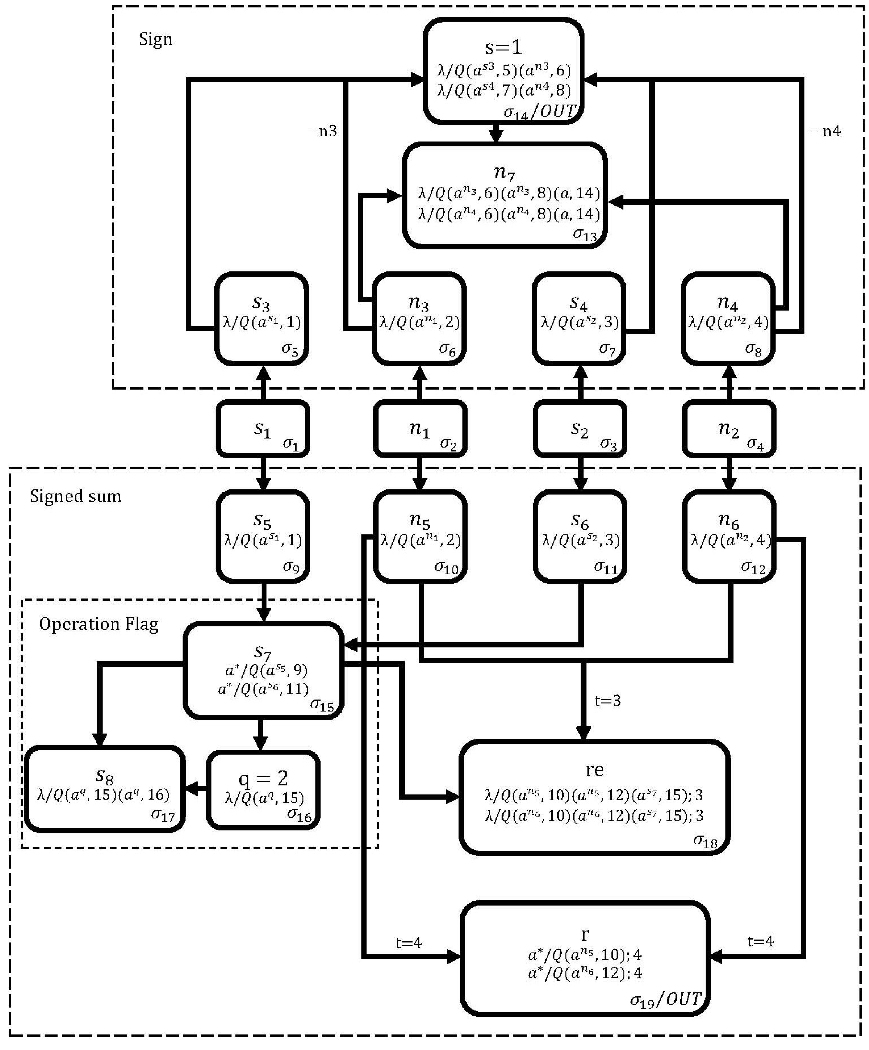
In Figure 3, we use 19 neurons to design the neural circuit to perform the operation . At the first simulation step, neurons and are loaded with the addends a and b, respectively, while neuron is loaded with the sign of a and neuron with the sign of b (zero spikes correspond to a positive sign and one spike to a negative sign). Neuron must be loaded with two spikes.

Figure 3.
The proposed membrane in SNQ P systems for adding signed numbers .
From the second to the fourth simulation steps, the sign membrane calculates the sign of the operation . In the second cycle, neurons , , , and are loaded with the values of neurons , , , and , respectively. In the third clock cycle, neuron extracts a spike from neuron (so will be activated in the next clock cycle). If neuron contains more spikes than neuron , then the rules in neuron assign spikes to neuron and zero spikes to neuron ; otherwise, it assigns zero spikes to neuron and spikes to neuron . In the fourth clock cycle, neuron will contain zero spikes and activate one of its two rules, indicating a negative value if the result of the operation is negative.
From the second to the sixth simulation steps, the signed sum membrane obtains the result of the operation in neuron . From the second to the fourth simulation steps, the operation flag membrane determines whether to add or subtract the operands, with zero or a spike stored in neuron if the operation is an addition or subtraction, respectively. Due to the delay in the synapse of neuron (), this neuron will be activated when the operation flag membrane has reached the halting condition and neuron contains a spike. At this moment, if neuron contains more spikes than neuron , the rules in neuron assign spikes to neuron and zero spikes to neuron ; otherwise, assign zero spikes to neuron and spikes to neuron . Finally, in the sixth step, the neuron adds the remaining spikes from the neurons and to obtain the final result in the signed sum membrane.
According to the formal definition of SNQ P systems, the proposed neural cipher circuit to perform the operation , which is shown in Figure 3, is mathematically expressed as follows.
where
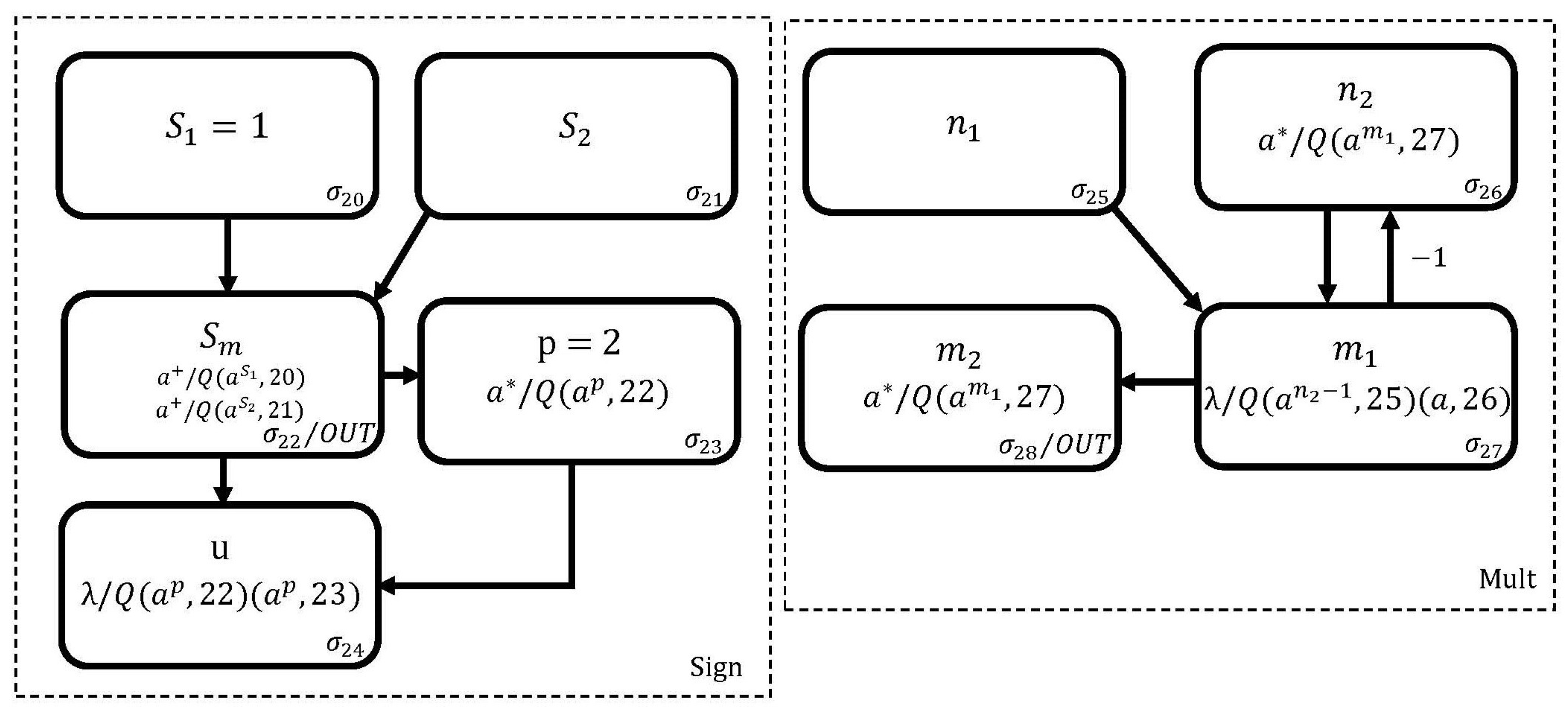
Multiplication of signed numbers. To operate , we use the membranes shown in Figure 3 and Figure 4. The Mult membrane in Figure 4 calculates the product as follows: Initially, neurons and are loaded with the values of the operands q and b, respectively. Starting from the second simulation step and continuing for q cycles, the neuron receives spikes b, which eventually accumulate in the neuron .

Figure 4.
The proposed membrane in SNQ P systems for performing the product .
The operation of the Sign membrane is as follows: In the first simulation step, the neuron is loaded with a spike to denote the sign of q, and the neuron is loaded with the sign of b. After one simulation step, neuron accumulates the spikes extracted from neurons and . Finally, the neuron performs the modulo 2 operation on the spikes contained in the neuron .
Once the sign and mult membranes reach the halting condition (at which point neuron contains the sign and neuron contains the product of the expression ), the query is established in neuron , as shown in Figure 3. Neurons , , , and are then loaded with the spike representing the sign of a, the value of a, the minus sign of , and the product value of obtained in neuron , respectively. In the next simulation step, the circuit in Figure 3 comes into operation so that, when it completes its calculations, the sign of will be in neuron and the result in neuron .
According to the formal definition of SNQ P systems, the proposed neural cipher circuit to perform the operation , which is shown in Figure 4, is mathematically expressed as follows.
where
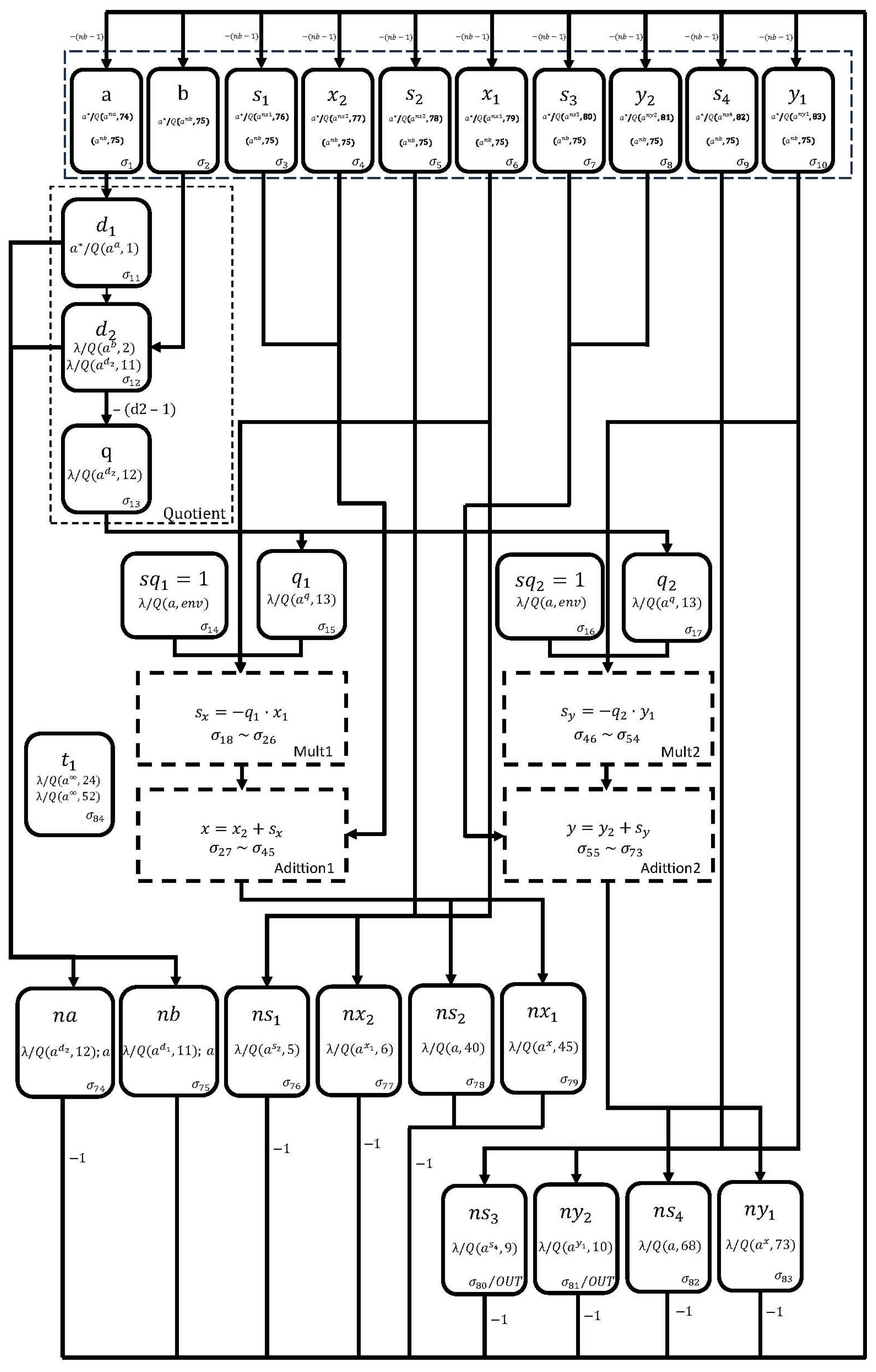
Extended Euclidean Algorithm (EEA): The Extended Euclidean Algorithm computes the greatest common divisor (GCD) of the integers a and b () and also finds the multiplicative inverse of b. The algorithm proceeds with the following steps as long as the condition is satisfied:
The initial values of the algorithm are: , , and . The design of the EEA neural circuit is shown in Figure 5. In the first simulation step, neurons 74 to 83 are initialized with zero spikes. Neurons , , , , , , , , , and are loaded with the values of a, b, the sign of , the value of , the sign of , the value of , the sign of , the value of , the sign of , and the value of , respectively.

Figure 5.
The proposed SNQ P system for performing the Extended Euclidean Algorithm.
In each simulation step, neurons 1 to 10 update their values according to Equation (1). Starting from the second simulation step, the Quotient membrane becomes active, and by the end of its operations, neurons , , and hold the values , b and the quotient , respectively.
When the membrane reaches the stop condition, neurons and are assigned a spike and quotient value obtained in neuron (the same process is applied to neurons and ), respectively.
In the subsequent clock cycles, the and membranes are executed to compute the products and , respectively. Both membranes function similarly to the membrane in Figure 4, but numbers its neurons from to , and numbers its neurons from to . When reaches the stopping condition, the sign and result of are stored in neurons and , respectively. Similarly, when reaches the halting condition, the sign and result of are stored in neurons and , respectively.
Once the and membranes have reached the halting condition, the and membranes begin their execution, respectively. The membrane calculates the operation with its neurons numbered from to . The sign and result of this operation (when reaches the stop condition) are stored in neurons and , respectively. Similarly, the membrane calculates the operation with its neurons numbered from to . The sign and result of this operation (when reaches the stop condition) are stored in neurons and , respectively.
When and membranes reach the stopping condition, neuron extracts all spikes from neurons and of the membrane shown in Figure 4 (note that the neuron relabeling for and corresponds to neurons and , respectively).
Once the membrane has reached the stopping condition, and after a delay of a simulation steps, neurons and are loaded with the value of b and , respectively.
Once the and membranes have reached the stopping condition, neurons , , , , , , , , , and are assigned the values a, b, , , , , , , , , respectively.
Finally, neurons and display the sign and value of the multiplicative inverse of b, respectively.
According to the formal definition of SNQ P systems, the proposed neural cipher circuit to perform the Extended Euclidean Algorithm, which is shown in Figure 5, is mathematically expressed as follows.
where
2.3.2. The Proposed Implementation of the ElGamal Decryption Process Based on SNQ P Systems
After the neural circuit for the Extended Euclidean Algorithm is obtained, the design of the decryption process for the ElGamal encryption algorithm is presented in Figure 6. Its description is as follows. The K membrane performs the same operation as the membrane in Figure 1, and it is now used to compute ; this result is stored in neuron .

Figure 6.
The proposed decipher circuit.
Neurons and extract the sign and value of b, respectively, from neurons and in the membrane corresponding to the Euclidean algorithm. If the sign of b is positive, neuron contains zero spikes, and neuron receives the value of the multiplicative inverse from neuron . If the sign of b is negative, the membrane is activated to calculate the value and assign it to neuron . Finally, the M membrane operates , and its operation is similar to that performed by the membrane described in Figure 2.
According to the formal definition of SNQ P systems, the proposed neural cipher circuit is mathematically expressed as follows.
where
3. Performance Evaluation
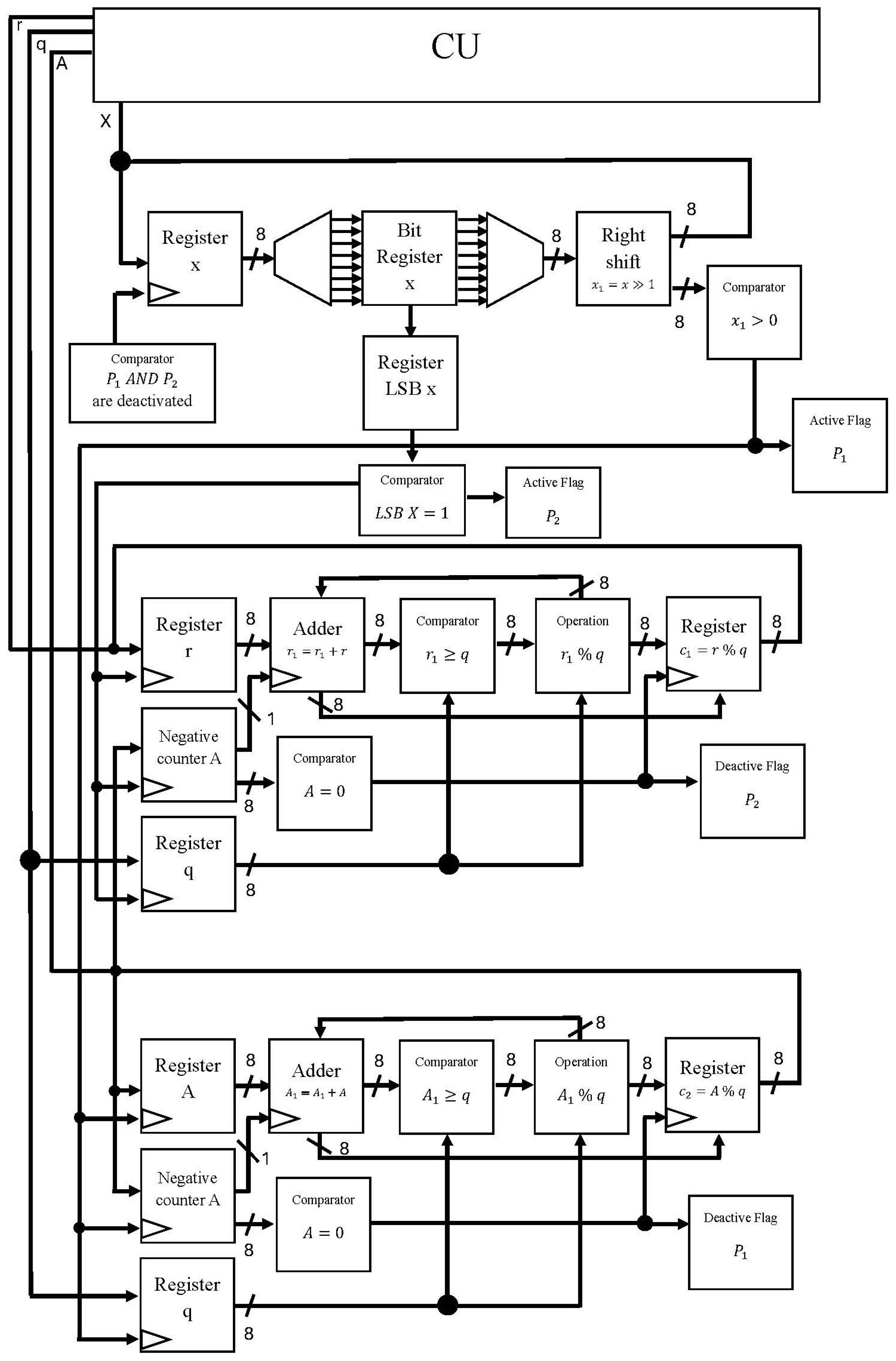
Here, we implement the proposed modular exponentiation neural circuit on an Intel Arria 10 GX 1150 FPGA, as shown in Figure 7. In this way, the proposed digital circuit processes the modular exponentiation neural circuit in parallel since this operation is the most demanding in terms of area and computational cost. To achieve this, we use basic digital components, such as registers, comparators, adders, and multiplexers. In particular, the use of these digital components has allowed us to mimic the neural behavior of the proposed modular exponentiation neural circuit.

Figure 7.
The proposed digital circuit.
In this work, we implement 15 complex neurons by consuming 28,750 logic elements (LE), which represent of the total, respectively. To obtain the power consumption of the MPU implementation, we use the ALTERA tool (Quartus Prime), for which the power consumption is 0.26 W. The static power consumption is 0.005 W, which is of the total power consumption and the dynamic power consumption is 0.255 W, which is of the total power consumption.
4. Conclusions and Future Work
This paper has introduced a new method for implementing the ElGamal cryptographic algorithm using SNQ P systems. We also outlined the implementation of the Extended Euclidean Algorithm using Spiking Neural P Systems with communication on request, which is crucial for calculating an integer’s multiplicative inverse in the ElGamal encryption algorithm’s decryption process. In addition, we incorporated delays in rules to improve communication mechanisms between neurons. Moreover, we conducted various tests to validate the effectiveness of our circuits. In general, our contributions highlight the potential of membrane computing, particularly SNQ P systems, in cryptography and secure communication. This work presents new opportunities to exploit the parallel processing capabilities of natural computing in cryptographic applications.
In future work, we plan to exploit the parallelism of membrane computing to further implement neural circuits that handle reliable key sizes in the ElGamal scheme. An alternative approach is to use addition chains to reduce the computational cost of ElGamal’s modular exponentiation.
Author Contributions
Conceptualization, G.S.; data curation, I.R. and E.V.; formal analysis, G.S.; funding acquisition, G.S.; investigation, I.R. and J.-G.A.; methodology, J.-G.A. and G.S.; resources, I.R. and G.D.; software, I.R. and D.-E.V.; supervision, G.D.; validation, I.R.; writing—original draft, E.V.; writing—review and editing all authors. All authors have read and agreed to the published version of the manuscript.
Funding
The authors would like to thank the Instituto Politécnico Nacional for its financial support.
Data Availability Statement
No new data were created or analyzed in this study. Data sharing is not applicable to this article.
Acknowledgments
The authors would like to thank the Consejo Nacional de Ciencia y Tecnología (CONACYT) and the IPN for financial support in creating this work.
Conflicts of Interest
The authors declare no conflicts of interest.
References
- Plesa, M.I.; Gheorghe, M.; Ipate, F.; Zhang, G. Applications of spiking neural P systems in cybersecurity. J. Membr. Comput. 2024, 8, 310–317. [Google Scholar] [CrossRef]
- Plesa, M.I.; Gheoghe, M.; Ipate, F.; Zhang, G. A key agreement protocol based on spiking neural P systems with anti-spikes. J. Membr. Comput. 2024, 4, 341–351. [Google Scholar] [CrossRef]
- Ganbaatar, G.; Nyamdorj, D.; Cichon, G.; Ishdorj, T. Implementation of RSA cryptographic algorithm using SN P systems based on HP/LP neurons. J. Membr. Comput. 2021, 3, 22–34. [Google Scholar] [CrossRef]
- Suzuki, D. How to Maximize the Potential of FPGA Resources for Modular Exponentiation. In Proceedings of the Cryptographic Hardware and Embedded Systems—CHES 2007, Vienna, Austria, 10–13 September 2007; Volume 10, pp. 272–288. [Google Scholar] [CrossRef]
- Pan, L.; Păun, G. Spiking Neural P Systems with Anti-Spikes. Int. J. Comput. Commun. Control 2009, 7, 273–282. [Google Scholar] [CrossRef]
- Krithivasan, K.; Metta, V.P.; Garg, D. On string languages generated by spiking neural P systems with anti-spikes. Int. J. Found. Comput. Sci. 2011, 1, 15–27. [Google Scholar] [CrossRef]
- Song, T.; Jiang, Y.; Shi, X.; Zeng, X. Small Universal Spiking Neural P Systems with Anti-Spikes. J. Comput. Theor. Nanosci. 2013, 4, 999–1006. [Google Scholar] [CrossRef]
- Pan, L.; Wang, J.; Hoogeboom, H.J. Spiking neural P systems with astrocytes. Neural Comput. 2011, 11, 805–825. [Google Scholar] [CrossRef] [PubMed]
- Zeng, X.; Xu, L.; Liu, X.; Pan, L. On languages generated by spiking neural P systems with weights. Inf. Sci. 2014, 9, 423–433. [Google Scholar] [CrossRef]
- Wang, J.; Hoogeboom, H.J.; Pan, L.; Păun, G.; Pérez-Jiménez, M.J. Spiking Neural P Systems with Weights. Neural Comput. 2010, 10, 2615–2646. [Google Scholar] [CrossRef] [PubMed]
- Zeng, X.; Pan, L.; Pérez-Jiménez, M.J. Small universal simple spiking neural P systems with weights. Sci. China Inf. Sci. 2014, 7, 1–11. [Google Scholar] [CrossRef]
- Zhang, X.; Wang, B.; Pan, L. Spiking neural P systems with a generalized use of rules. Neural Comput. 2014, 12, 2925–2943. [Google Scholar] [CrossRef] [PubMed]
- Song, T.; Xu, J.; Pan, L. On the Universality and Non-Universality of Spiking Neural P Systems with Rules on Synapses. IEEE Trans Nanobiosci. 2015, 12, 960–966. [Google Scholar] [CrossRef] [PubMed]
- Su, Y.; Wu, T.; Xu, F.; Păun, A. Spiking Neural P Systems with Rules on Synapses Working in Sum Spikes Consumption Strategy. Fundam. Informaticae 2017, 10, 187–208. [Google Scholar] [CrossRef]
- Cavaliere, M.; Ibarra, O.H.; Păun, G.; Egecioglu, O.; Ionescu, M.; Woodworth, S. Asynchronous spiking neural P systems. Theor. Comput. Sci. 2009, 3, 2352–2364. [Google Scholar] [CrossRef]
- Song, T.; Pan, L. A small universal spiking neural P systems with cooperating rules. Rom. J. Inf. Sci. Technol. 2014, 7, 177–189. [Google Scholar]
- Carbale, F.; Ardona, H.; Jiang, M.; Zeng, X. Spiking Neural P Systems with Scheduled Synapses. IEEE Trans. Nanobiosci. 2017, 10, 99. [Google Scholar] [CrossRef]
- Pan, L.; Păun, G.; Zhang, G.; Neri, F. Spiking Neural P Systems with Communication on Request. Int. J. Neural Syst. 2017, 12, 1750042. [Google Scholar] [CrossRef] [PubMed]
- Ionescu, M.; Păun, G.; Yokomori, T. Spiking neural P systems. Fundam. Informaticae 2006, 6, 279–308. [Google Scholar] [CrossRef]
- Wu, T.; Bîlbîe, F.-D.; Paun, A.; Pan, L.; Neri, F. Simplified and yet Turing Universal Spiking Neural P Systems with Communication on Request. Int. J. Neural Syst. 2018, 4, 1–19. [Google Scholar] [CrossRef] [PubMed]
Disclaimer/Publisher’s Note: The statements, opinions and data contained in all publications are solely those of the individual author(s) and contributor(s) and not of MDPI and/or the editor(s). MDPI and/or the editor(s) disclaim responsibility for any injury to people or property resulting from any ideas, methods, instructions or products referred to in the content. |
© 2025 by the authors. Licensee MDPI, Basel, Switzerland. This article is an open access article distributed under the terms and conditions of the Creative Commons Attribution (CC BY) license (https://creativecommons.org/licenses/by/4.0/).