Article

Compressible Navier-Stokes Equations in Cylindrical Passages and General Dynamics of Surfaces—(I)-Flow Structures and (II)-Analyzing Biomembranes under Static and Dynamic Conditions

by
Terry E. Moschandreou
1,*,† and
Keith C. Afas
2,†
1
Department of Applied Mathematics, Faculty of Science, Western University, London, ON N6A 5C1, Canada
2
Department of Medical Biophysics, Faculty of Medical Science, Western University, London, ON N6A 5C1, Canada
*
Author to whom correspondence should be addressed.
These authors contributed equally to this work.
Mathematics 2019, 7(11), 1060; https://doi.org/10.3390/math7111060
Submission received: 31 August 2019 / Revised: 18 October 2019 / Accepted: 27 October 2019 / Published: 5 November 2019

Abstract

:
A new approach to solve the compressible Navier-Stokes equations in cylindrical co-ordinates using Geometric Algebra is proposed. This work was recently initiated by corresponding author of this current work, and in contrast due to a now complete geometrical analysis, particularly, two dimensionless parameters are now introduced whose correct definition depends on the scaling invariance of the N-S equations and the one parameter δ defines an equation in density which can be solved for in the tube, and a geometric Variational Calculus approach showing that the total energy of an existing wave vortex in the tube is made up of kinetic energy by vortex movement and internal energy produced by the friction against the wall of the tube. Density of a flowing gas or vapour varies along the length of the tube due to frictional losses along the tube implying that there is a pressure loss and a corresponding density decrease. After reducing the N-S equations to a single PDE, it is here proven that a Hunter-Saxton wave vortex exists along the wall of the tube due to a vorticity argument. The reduced problem shows finite-time blowup as the two parameters δ and α approach zero. A rearranged form for density is valid for δ approaching infinity for the case of incompressible flow proving positive for the existence of smooth solutions to the cylindrical Navier-Stokes equations. Finally we propose a CMS (Calculus of Moving Surfaces)–invariant variational calculus to analyze general dynamic surfaces of Riemannian 2-Manifolds in R 3 . Establishing fluid structures in general compressible flows and analyzing membranes in such flows for example flows with dynamic membranes immersed in fluid (vapour or gas) with vorticity as, for example, in the lungs there can prove to be a strong connection between fluid and solid mechanics.

1. Introduction

Compressible flow has many applications some of which are of physics, mathematics and engineering interest. The flow in a pipe is important in industry and specifically arises in nozzle and diffuser flow in engines.The Navier Stokes equations have been dealt with in the literature for both analytical [1,2] and numerical solutions [3,4,5]. Mathematical and computational methods for compressible flow have been outlined in References [6,7,8]. Incompressible flow between parallel plates with radial pressure gradient has been carried out in Reference [9]. The existence and uniqueness of solutions for non-autonomous reaction-diffusion equations with delay, and the existence of a pullback asymptotically compact process is examined in Reference [10]. Boundary layer flow over a moving flat plate with second-order velocity slip, injection and applied magnetic field is presented in Reference [11]. Given the nature and highly nonlinear structure of the Navier-Stokes compressible equations, important work has been presented in nonlinear dynamics for the intermittent transition to chaos in a strong nonlinear non-smooth discontinuous system [12]. Gibbs [13] demonstrated that complex vectors are useful in the formulation of complex harmonic motion and referred to them as bivectors. An imaginary vector is defined as a sum of two real vectors one of which is multiplied by the complex number i. If we take the complex number i and replace it by a pseudo-scalar I in the context of Geometric Algebra it can be shown that for compressible flow the density appearing in the Navier-Stokes equations can be written in terms of a “complex” exponential function in time or, even better, an exponential of a multivector which can be proven to be well defined [14]. The form of a complex vector has been used as a bivector to study polarization of electric fields [15,16]. The advantage of the use of complex vector in terms of pseudo-scalar is that it gives further geometric insight into the problem of the orientation in the plane of rotation in space for the motion of fluid. The Navier Stokes equations can be rewritten in a way using the continuity equation such that a complex vector is an element of a newly transformed partial differential equation. This will be in the form of a sum of a vector in the usual sense of vector in three dimensional space added to a bivector in the GA sense. Multiplication of complex vectors by rotors can rotate the vector by an angle θ in the plane of the vector and bivector [14]. The fundamental lemma of Geometric-Algebra is that the geometric product can be decomposed into an inner product and outer product of two complex vectors. It can be proven that the bivector product of two complex vectors is a complex vector. With this in mind we introduce complex vectors for the representation of the inertial term f = a · a and the velocity b = a ρ . In the transformation of the governing Navier Stokes equations it can be proven that there is a density time dependent derivative present in the transformed equation which presents a pseudo-scalar in the transformed Navier-Stokes-Continuity equations. The stage is set to discuss solutions to two types of problems one which is in the setting of Geometric Algebra/Calculus using multivectors and the second type of solution being one in which the elements of the partial differential equations derived are not complex vectors(exponential function in time variable is not multivector dependent). We attempt to address one type of solution, the simpler one which leads to the existence of a Hunter-Saxton wave vortex in the large regimes of fluid flowing in a horizontal tube configuration. In the present work the full 3D compressible cylindrical Navier-Stokes equations are reduced using a new procedure to a Hunter-Saxton equation expressed in terms of the azimuthal angle in the flow. Also it is shown that there exists a complex vector F which can be expressed as F = f + I c b with multivectors as discussed above. Here we are interested in the angle in both the plane of rotation and outside the plane of rotation between the vectors b and f in the plane I. Finally it is of interest to define an equation in density related to the non-dimensional parameter δ defined in the scale invariance of the Navier-Stokes equations. By solving this equation it is observed that there is a decrease in density downstream along the pipe due to frictional and pressure losses for the vapour or gas flowing. The incompressible case is addressed as well for a non-blowup result.
Having introduced the goal of the paper for fluid dynamics of compressible flow in a tube at this stage of the paper, we are interested in further establishing a theoretical means to discuss the interaction of vortices with solid and flexible walls of tubes. Impingement of vortices on small biomembranes immersed inside tubes is also of general interest. These biological structures undergo large deformations under forces induced by vortices. Given this we now discuss a framework to analyze such membranes first in general and then with connection to fluid dynamics. It is important to do this in order to formulate a language to discuss fluid-membrane interaction problems in general. Variational Calculus is extremely useful in deriving laws regarding physical phenomena by minimizing the total energy required to form a system [17]. How such a system evolves may be determined by variating the integral of the total energy density known as the Action S of the system. This method of analyzing membranes has been often used in several physical fields such as physics and chemistry but is not seen as widespread in the Biomedical Sciences, particularly where it would have potential for analyzing Biological Phospholipid Bilayer Membranes [18].

1.1. Importance of Analyzing Biomembranes

In Biophysics, there are a few applications for which developing a framework to analyse Biocellular Membranes may be of utility:
  • It is well established that the morphology of cells is related in a complicated manner to various pathologies contained within the cell. This is exhibited in several elementary examples found in References [19,20].
  • In addition, Electric and Magnetic Fields that permeate the space around Biological Cells can polarize cell fibers within tissue resulting in contractile properties, particularly in myocyte cultures which affects their overall morphology [21,22].
  • Finally, there is extensive literature on Bioelectromagnetic Dosimetry (BEM) and documenting its effects on cardiac function and thermal energy transfer; these results have been classically obtained by applying steady uni-directional electromagnetic fields in Human & Animal Models [23]. Information gleaned from such experiments are utilized to analyze biological tissue cultures under microwave electromagnetic frequencies.
Thus, several areas in biophysics see effects on biological cells and tissue cultures under interaction with fields and chemical attraction. Several methods have been developed recently to analyze these phenomenon, however there is a need to merge several approaches as individually, they contain restrictions which prohibit them from fully analyzing all aspects of biological phenomena.

1.2. Prominent Approaches and Shortcomings

Two prominent approaches merit a mention—A strictly Hamiltonian Variational Approach, and an Approach using the Calculus of Moving Surfaces (CMS):
  • A Variational Hamiltonian Approach: This method, drawing on inspiration from Statistical Mechanics attempts to derive a Hamiltonian-like expression of the Total Energy Density present on a surface, and variates this density with respect to the configuration of the surface [24,25]. This method has found application in explaining several steady microscopic morphological phenomena in cells, such as Terasaki Spiral Ramps [24], Rod Inclusions, and providing several Mechanochemical models for ‘Active Surfaces’
    -
    Shortcomings: While the approach is extremely effective in generating equilibrium conditions for biomembranes under a specific Energy Density using tensors in a coordinate-free manner, the framework simply does not contain the support to extend the analysis for Biomembranes which are not steady and stationary; in a biological context this dynamic nature of cells are of crucial importance.
  • A “Calculus of Moving Surfaces” Approach: This method draws on inspiration from the recent Calculus of Moving Surfaces (CMS) [18]; CMS outlines a tensor framework which can be used to analyze surface membranes in motion denoted by Σ t . CMS demonstrates the perilous nature of several vector fields used to study dynamic membranes such as the velocity of the membrane, asserting that they are not proper tensors on Σ t with respect to coordinate changes. CMS proceeds to introduce operators and tensors on Σ t which do behave as tensors and can be used to analyze tensors and differential forms defined on Σ t . CMS has found application to Cellular Membranes in several papers [26,27] by tentatively proposing a CMS-derived method for modelling Membranes with no energy density on their surface, as well as being acted on by electromagnetic fields E [28].
    -
    Shortcomings: While the above method has yielded valuable insight in the mechanics of dynamic surfaces providing several biomembrane models [26,27,28], the models are non-tensorial including several objects from classical mechanics such as V α V α and others which do not transform as tensors as per CMS [18]. Clearly, the mode obvious problem is that while formulated using CMS, it is difficult to identify symmetries and the significance of terms within the energy density which agree with classical physics, and also are CMS-tensorial. Thus, constants of motion cannot be readily obtained as can be in other more classical applied analysis methods.
Therefore, in order to produce meaningful models which reflect Biomembranes accurately, an approach must be developed which is not only grounded in a variational analysis as proposed in Reference [25], but must also capture dynamic properties of Biomembranes. This will ultimately allow for models which can be used to predict the time-dependent evolution of biomembranes in accordance with CMS-framework [18].
The paper is organized into two parts, the first is (i) Flow Structures and the second is (ii) Analyzing Biomembranes under Static and Dynamic Conditions. The discussion consists of a relationship between these two parts with a conclusion connecting and summarizing these.

2. Flow Structures

2.1. A New Composite Velocity Formulation

The 3D compressible cylindrical unsteady Navier-Stokes equations are written in expanded form, for each component, u r , u θ and u z :
u r t + u r u r r + u θ r u r θ u θ 2 r + u z u r z μ ρ u r r 2 + 2 u r r 2 + 1 r u r r + 1 r 2 2 u r θ 2 2 r 2 u θ θ + 2 u r z 2 μ 3 ρ r u r r + 1 r u r θ + u r z + 1 ρ p r F g r = 0
u θ t + u r u θ r + u θ r u θ θ + 1 r u r u θ + u z u θ z μ ρ u θ r 2 + 2 u θ r 2 + 1 r u θ r + 1 r 2 2 u θ θ 2 + 2 r 2 u r θ + 2 u θ z 2 1 r μ 3 ρ θ u θ r + 1 r u θ θ + u θ z + 1 ρ r p θ F g θ = 0
u z t + u r u z r + u θ r u z θ + u z u z z μ ρ 2 u z r 2 + 1 r u z r + 1 r 2 2 u z θ 2 + 2 u z z 2 μ 3 ρ z u z r + 1 r u z θ + u z z + 1 ρ p z F g z = 0
where u r is the radial component of velocity, u θ is the azimuthal component and u z is the velocity component in the direction along tube, ρ is density, μ is dynamic viscosity, F g r , F g θ , F g z are body forces on fluid. The total gravity force vector is expressed as F T = ( F g r , F g θ , F g z ) . The following relationships between starred and non-starred dimensional quantities together with a non-dimensional quantity δ are used:
u r = 1 δ u r *
u θ = 1 δ u θ *
u z = 1 δ u z *
r = δ r *
θ = θ *
z = δ z * , t = δ 2 t *
In the above the scale invariance of the Navier-Stokes equations is evident and will be shown in this paper. A similar approach was adopted in Reference [29] for the definition of δ , however the mathematics is made precise with the physics improved by deriving the density as follows,
Theorem 1.
For compressible Navier Stokes equations defined on a surface where the radial velocity u r * will vanish and axial velocity u z * is increasing linearly in the developing flow region in tube, as u z * = β z * , β > 0 , the density can be expressed as,
ρ = ρ 0 + Φ ( r , θ , z , t ) 2 / γ F ( r , z , t )
for arbitrary function F and γ = 1.4 ratio of specific heats assuming adiabatic condition,
ρ = ( ρ ρ 0 ) γ ( η + u θ ( r , θ , z , t ) 2 ) 1
where η is a constant. Moreover the derivative of u θ with respect to θ blows up in finite time if and only ρ is in the form above and Φ and F are both separable, that is,
Φ = F 1 ( r ) F 2 ( θ ) F 3 ( z ) F 4 ( t ) , F = F a ( r ) F b ( z ) F c ( t )
where F 4 ( t ) and F c ( t ) are are arbitrary functions of time variable t.
Proof of Theorem 1. 
Substitute ρ = ( ρ ρ 0 ) γ ( η + u θ ( r , θ , z , t ) 2 ) 1 and blowup form, b 2 = u θ = ϕ A 1 t + B 1 into left side of Equation (35) on page 12 using continuity Equation (29) on page 11. Simplification using Maple 19 results in an equation where the blowup condition is set as A 1 = B 1 / t and the resulting pde has two factors of which one has a solution of the form, ρ = ρ 0 + Φ ( r , θ , z , t ) 2 / γ F ( r , z , t ) and substitution of this form of ρ into the other factor of pde, gives a solution which is fully separable for Φ and F. This proves the one direction of the theorem. Furthermore the function Φ = G 2 2 r B 1 θ t , for arbitrary function G, using the right hand side of Equation (35) i.e., the equation for Q. The fact that Φ is separable from left side of Equation (35) implies that G 2 = 0 . This allows us to determine F and its factors. The opposite direction of the theorem is the focus of the first part of the paper, that is if the density is expressed as above then there is blowup in the first derivative of u θ . □
The density is defined given Theorem 1 as,
ρ = i ρ 1 sin ( α θ ) α θ α θ ( π , 0 ) , ρ 1 sin ( α θ ) α θ α θ ( 0 , π )
where i = 1 , α > 0 , ρ 1 is a function derived below, and further below in this paper a geometric proof is shown that the sign of the radial velocity u r will change on a surface given by z * = r * 2 θ * 2 . It can also be observed that the density as defined above is real valued on ( π , π ) .
A density equation used for compressible flow is,
δ = ρ 1 ( r , θ , z , t ) θ + z ρ 1 ( r , θ , z , t ) z + ρ a v g r ρ 1 ( r , θ , z , t ) r + ρ 1 ( r , θ , z , t ) r
with general solution,
ρ 1 ( r , θ , z , t ) = ρ a v g δ + F ρ θ δ + ln ( r ) δ , z r 1 δ , t r
where ρ a v g is an averaged density over space and time in the flow.
A specific physical form of solution derived immediately from the general one is given as
ρ 1 = ρ a v g δ + i ξ i exp θ i δ + ln ( r ) δ 2 r 1 δ 1 1 z exp ( c t )
Here at the inlet of the pipe at z = 0 we obtain a Dirac Delta type function and the density of vapour or gas is decreasing down the pipe due to frictional losses, hence pressure losses. The choice of weight coefficients ξ i and variable values θ i are so that we have high pressure at the centre of the tube and low pressure near the wall. The values of δ ( 0 , ) . It is also assumed δ is small but not zero, so that r * will be large. At the end of the paper for computational simplicity we consider θ i = 0 and look at the one term which is maximum in the series in Equation (12). Also Theorem 1 is true when θ i = 0 . In Appendix C a more correct density expression is given but will be reserved for a future paper detailing the implications of a non-Hunter Saxton wave vortex also using Theorem 1.
Replacing Equations (11) and (12) in Reference [29], we use new Equations (4)–(9) above, multiplying scale invariant Equations (1)–(3) by Cartesian unit vectors e r * = ( 1 , 0 , 0 ) , 2 e θ * = ( 0 , 2 , 0 ) and k = ( 0 , 0 , 1 ) respectively and adding modified equations for Equations (1)–(3) giving the following equations, for the resulting composite vector L 1 = 1 δ u r * * e r * + 2 δ u θ * * e θ * + 1 δ u z * * k ,
δ 3 ( L 1 t + u r * * δ 2 L 1 r * + u θ * * δ 2 r * L 1 θ * + 1 δ 2 u z * * L 1 z * 1 δ 3 r * u θ * * 2 e r * + 1 δ 3 r * u r * * u θ * * e θ * μ ρ δ 2 L 1 r * 2 + δ 2 2 L 1 r * 2 + δ 2 1 r * L 1 r * + δ 2 1 r * 2 2 L 1 θ * 2 + 2 δ 2 r * 2 2 δ u r * * θ * e θ * 1 δ u θ * * θ * e r * + δ 2 2 L 1 z * 2 1 δ 3 μ 3 ρ r * u r * * r * + 1 r * u r * * θ * + u r * * z * e r * 1 δ 3 r * μ 3 ρ θ * u θ * * r * + 1 r * u θ * * θ * + u θ * * z * e θ * μ 3 δ 3 ρ z * u z * * r * + 1 r * u z * * θ * + u z * * z * k + 1 δ ρ p r * e r * + 1 δ r * ρ p θ * e θ * + 1 δ ρ p z * k F T ) = 0
δ 3 ( L 1 t + L 1 δ L 1 r * + L 1 δ r * L 1 θ * + L 1 δ L 1 z * 1 δ 3 r * u θ * * 2 e r * + 1 δ 3 r * u r * * u θ * * e θ * μ ρ δ 2 L 1 r * 2 + δ 2 2 L 1 r * 2 + δ 2 1 r * L 1 r * + δ 2 1 r * 2 2 L 1 θ * 2 + 2 δ 2 r * 2 2 δ u r * * θ * e θ * 1 δ u θ * * θ * e r * + δ 2 2 L 1 z * 2 μ 3 δ 3 ρ r * u r * * r * + 1 r * u r * * θ * + u r * * z * e r * 1 δ 3 r * μ 3 ρ θ * u θ * * r * + 1 r * u θ * * θ * + u θ * * z * e θ * μ 3 δ 3 ρ z * u z * * r * + 1 r * u z * * θ * + u z * * z * k + 1 δ ρ p r * e r * + 1 δ r * ρ p θ * e θ * + 1 δ ρ p z * k F T ) = 0
expanding previous 2 equations leads to, due to invariance of Navier Stokes equations, L 2 = u r * * e r * + 2 u θ * * e θ * + u z * * k . Here the δ drops out of the equation.

2.2. A Solution Procedure for δ Arbitrarily Small in Quantity

Multiplication of Equation (14) by ρ and Equation (15) below by L 1 , addition of the resulting equations [29], and using the ordinary product rule of differential multivariable calculus a form as in Equation (16) is obtained whereby a is given by a = ρ L 2 .
The continuity equation in cylindrical co-ordinates is
ρ t * + u r * * ρ r * + u θ * * r * ρ θ * + u z * * ρ z * = ρ u r * * r * + u r * * r * + 1 r * u θ * * θ * + u z * * z * = ρ L ¯
ρ a t + a · a + ρ 2 b · b ρ r * u θ * * 2 e r * + ρ r * u r * * u θ * * e θ * = 2 r * 2 2 u r * * θ * e θ * u θ * * θ * e r * + μ 2 b + 1 3 ( · b ) + P + F T
Taking the geometric product in the previous equation with the inertial vector term,
f = a · a
where b = a ρ is defined, where in the context of Geometric Algebra, the following scalar and vector grade equations arise,
f · ρ 2 b t + ρ b ρ t + f 2 + b · f ρ 2 · b ρ r * u θ * * 2 f · e r * + ρ r * u r * * u θ * * f · e θ * = 2 r * 2 2 u r * * θ * f · e θ * u θ * * θ * f · e r * + μ f · 2 b + μ 3 f · ( · b ) + f · P + f · F T
ρ 2 b t + ρ b ρ t + b ρ 2 · b ρ r * u θ * * 2 e r * + ρ r * u r * * u θ * * e θ * = 2 r * 2 2 u r * * θ * e θ * u θ * * θ * e r * + μ 2 b + 1 3 ( · b ) + P + F T
The geometric product of two vectors [30] is defined by A B = A · B + A × B . Taking the divergence of Equation (19) results in
ρ 2 t · b + ρ ρ t · b + b · ( ρ ρ t ) + · ( b ρ 2 · b ) + Div = · μ 2 ( b + Ψ μ 3 · ( · b ) + · P + · F T
with the divergence of the following non-linear terms,
Div = · ρ r * u θ * * 2 e r * + 2 ρ r * u r * * u θ * * e θ * = r * ρ r * u θ * * 2 2 ρ r * u θ * * u θ * * r * + 2 θ * ρ r * 2 u r * * u θ * * + 2 ρ r * 2 u r * * u θ * * θ * + 2 ρ r * 2 u θ * * u r * * θ *
Div = 2 ρ r * u θ * * u θ * * r * + 2 ρ r * 2 u r * * u θ * * θ * l 1 ( θ * ) 2 r * 2 u r * * u θ * * + 2 ρ r * 2 u r * * u θ * * θ * + 2 ρ r * 2 u θ * * u r * * θ * , θ * ( π , 0 ) , 2 ρ r * u θ * * u θ * * r * + 2 ρ r * 2 u r * * u θ * * θ * i l 1 ( θ * ) 2 r * 2 u r * * u θ * * + 2 ρ r * 2 u r * * u θ * * θ * + 2 ρ r * 2 u θ * * u r * * θ * , θ * ( 0 , π )
where l 1 ( θ * ) = i / 2 cos θ * α α θ * + sin θ * α α θ * 2 1 sin θ * α θ * α , and which becomes
Div = 2 ρ r * u θ * * × b z l 1 ( θ * ) 2 r * 2 u r * * u θ * * + 2 ρ r * 2 u r * * u θ * * θ * + 2 ρ r * 2 u θ * * 2 , θ * ( π , 0 ) , 2 ρ r * u θ * * × b z i l 1 ( θ * ) 2 r * 2 u r * * u θ * * + 2 ρ r * 2 u r * * u θ * * θ * + 2 ρ r * 2 u θ * * 2 , θ * ( 0 , π )
where vorticity in the z * direction appears. It will be assumed for now that the vorticity is linear in r * and separable in r * from remaining independent variables. It can be generalized to a form r * F ( r * , θ * , z * , t * ) with the restricton that F is increasing in r * towards the wall of the tube. For the moment, Div=0 will be set without justification and δ 0 (but not zero) which imply,
u r * * = 2 u θ * * sin ( α θ * ) θ * ω 3 r * u θ * * 2 sin ( α θ * ) θ * u θ * * θ * u θ * * cos ( α θ * ) α θ * + sin ( α θ * ) θ * ( π , 0 ) , 2 u θ * * sin ( α θ * ) θ * ω 3 r * u θ * * 2 sin ( α θ * ) θ * u θ * * θ * u θ * * cos ( α θ * ) α θ * + sin ( α θ * ) θ * ( 0 , π ) ,
The fact that the vorticity is twice the angular velocity ( ω = 2 ω A ) is used; it can be seen that the angular velocity will be high near the wall due to viscous friction and negligible near r * = 0 .
The angular velocity of a fluid particle in 3D is,
ω A = r × u | r | 2
and as a result, the vorticity ω 3 is calculated as,
ω 3 = 2 | r | 2 r * u θ * * θ * u r * * ,
Substitution into the formula for u r * * above and solving for u r * * results in,
u r * * = 2 u θ * * 2 θ * sin ( α θ * ) r * 2 θ * 2 z * 2 × ( 2 θ * sin ( α θ * ) ( r * 2 + θ * 2 + z * 2 ) u θ * * θ * + ( ( ( 4 r * + 1 ) θ * 2 + r * 2 + z * 2 ) sin ( α θ * ) + α θ * cos ( α θ * ) ( r * 2 + θ * 2 + z * 2 ) ) u θ * * ) 1
The radial velocity, u r * * , depends on the terms u θ * * and hyperbolic part, r * 2 θ * 2 z * 2 . The sign of the radial velocity will change on the surface given by z * = r * 2 θ * 2 .

2.3. Characterization of the Sign of the Vorticity

The cylindrical function z * 2 = r * 2 θ * 2 defines interior and exterior regions where the radial velocity will be positive and conversely negative; the radial velocity will vanish on regions which belong to the cylindrical surface outlined by the cylindrical function. Graphing modalities encounter difficulties due to plotting softwares protocols in handling square root functions. This cylindrical function has a natural representation which can be found by warping the cylindrical coordinate system from ( r * , θ * ) to ( ϕ , ξ ) which is outlined by the substitution { r * = ϕ cosh ξ , θ * = ϕ } . This transformation has the surface jacobian outlined by:
J α α = cosh ξ ϕ sinh ξ 1 0
In this natural representation, the Radial Velocity null-surface is outlined by:
x = ϕ cosh ξ cos ϕ ϕ cosh ξ sin ϕ ϕ sinh ξ , ξ [ 0 , ξ max ] , ϕ [ 0 , ϕ max ]
where ξ max is specified to be coincident with a cylinder of radius r * = r max oriented along the z-axis at the value z * = z max . Since it is known that the conditions specify the equalities z max = ϕ max sinh ξ max and r max = ϕ max cosh ξ max , the value of ξ max can be given by
tanh ξ max = z max r max , ϕ max 2 = r max 2 z max 2
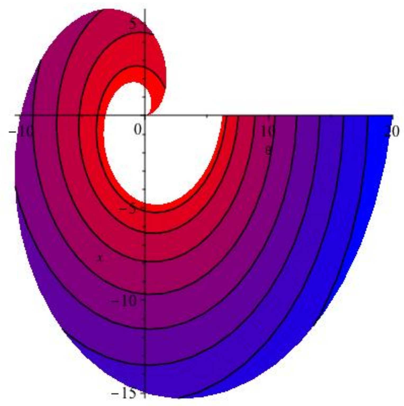
This image can be plotted continuously (See Figure 1, Figure 2 and Figure 3). An important property of this surface is that taking the cylindrical representation of the function, in the large regimes of r, the function reduces to a cone. This represents the quality that far from the center of the tube, the induced vorticity dissipates near the wall. At infinity for z * , we approach a perfect circle as shown partially in Figure 1.

2.4. Non-Linear Further Reduction

The other nonlinear terms in Equation (19), that is, 2 r * 2 2 u r * * θ * e θ * u θ * * θ * e r * have a divergence equal to,
4 2 θ * 2 u r * * r * , θ * , z * , t * r * 3 + 4 θ * u θ * * r * , θ * , z * , t * r * 3 2 2 θ * r * u θ * * r * , θ * , z * , t * r * 2
which is equal to
θ * 4 r * 2 [ × b ] z * 2 r * 2 u θ * * r * 8 r * 2 u θ * * r * = θ * ( 4 r * 2 ω 3 r * , θ * , z * , t * r * 2 2 ω 3 r * , θ * , z * , t * 4 r * 2 ω 3 r * , θ * , z * , t * )
The value of r * is chosen to be large as mentioned previously for δ small in value. This implies that the above expression is negligible and can be omitted from the subsequent analysis. This is true since ω 3 is assumed to be linear in r * as will be further clarified below. It is known that the three dimensional vorticity controls the breakdown of smooth solutions of the 3D Euler equations [31].
We denote the following in Equation (18)
Ψ = 2 r * 2 2 u r * * θ * f · e θ * u θ * * θ * f · e r *
and in Equation (19) we denote by ψ
ψ = · 2 r * 2 2 u r * * θ * e θ * u θ * * θ * e r *
As it will be shown in this work, for r * not very large so that the flow is confined to a central core in the tube, the term ψ is significant but not unbounded on t * ( 0 , ) . It is only when r * that solutions breakdown outside the central core in the vicinity of the wall of the tube. So ψ dependent on ω 3 does control the breakdown of smooth solutions of the 3D compressible equations as will be seen in this study.
The expression f · Ψ in Equation (18) will vanish further below when we take a dot product in the z * direction of flow or k direction downstream in tube. We therefore do not include it after Equation (27) below. Upon multiplication of Equation (20) by,
H = ρ b · f ρ t
the resulting equation is
ρ 2 H t ( · b ) + ρ 2 b · f · b + H b · ( ρ ρ t ) + H · ( b ρ 2 · b ) = μ H · 2 b + μ 3 H · ( ( · b ) ) + H · ( P ) + H · ρ F T
which results upon using Equation (18) in,
ρ 2 H t ( · b ) f · ρ 2 b t + ρ b ρ t f 2 f · 2 b μ 3 f · ( · b ) f · P + H b · ( ρ ρ t ) + H · ( b ρ 2 · b ) = μ H ( · 2 b ) μ 3 H · ( ( · b ) ) + H · P + H · ρ F T + Ψ
The continuity equation is written in terms of b as,
ρ t + ρ · b + b · ρ = 0
and
· b = 1 ρ ρ t 1 ρ ρ · b
where the following compact expression is given,
Y * = · b
Multiplying by ( f · f ) 1 in Equation (27) and, using properties of third derivatives involving the gradient and in particular the fact that the Laplacian of the divergence of a vector field is equivalent to the divergence of the Laplacian of a vector field, leads to the following form,
W * Y * t G ( ρ , ρ t ) W * F ( ρ , ρ t ) b f ( 1 + f · P ) ρ 2 V ( μ ) W * 2 ( Y * ) b f ρ t ρ 1 f 2 f · b t + Ω b f ρ t ρ 3 f 2 μ f · 2 b b f ρ t ρ 3 f 2 μ 3 f · ( · b ) ρ 2 b f 1 f 2 b · f · b ρ 2 · b + P + ρ F T = 0
where Ω = ρ 2 H b · ( ρ ρ t ) in Equation (31) and,
W * = f · b f 2 f b = f · b f 2 f · b + f · b f 2 f × b = ξ + f × f · b f 2 b
This involves the vector projection of b onto f which is written in the conventional form,
proj f b = f · b f 2 f
Equation (31) can be written compactly as
Y * t G ( ρ , ρ t ) ρ 2 V ( μ ) 2 Y * ρ 2 2 P = U f Q ( ρ , ρ t , b , b t , P , F T ) + f U f b
where U f ξ is the scalar projection for b , G = 1 ρ 2 ρ t 2 , Q (a differential operator defined by Equations (19) and (31) and hence for a constant positive function α ,
Y * t G ( ρ , ρ t ) ρ 2 V ( μ ) 2 Y * ρ 2 2 P = Q ( ρ , ρ t , b , b t , P , F T ) + f b = α 0
with solution in terms of a function B ,
Y * = · b = B ( α , r , θ , z , t )
At this stage of the analysis we introduce the vorticity equation for compressible flow,
ω t + ( a · ) ω = ( ω · ) a ω ( · a ) + ρ ρ 2 × P + × ( · τ ρ ) + × ( F ρ )
We consider the third component of the vorticity equation in z * . It is assumed that the vorticity is an exponential function of z * and t * , ie ω = r * G ( θ * ) e tanh α z * e tanh α t * , for some general function of θ * . Recall that a 1 = ρ b 1 = 0 on surface r * 2 θ * 2 z * 2 = 0 , a 2 = ρ b 2 = 1 2 r * ω ( r * , θ * , z * , t * ) ( r * 2 + θ * 2 + z * 2 ) . This can be non-zero except at the center of the tube where there the flow is irrotational, also G ( θ * ) 0 further away from the center of tube. Substitution of this form of ω into the vorticity equation and letting a 3 * be an increasing linear function in the form β z * , results in · a being solved for and expanded in a series for small α and large β , resulting in,
· b = O ( 1 / r * )
It is worthy to note that ρ is decreasing down the tube and a 3 * is increasing and this is physically true for gas pipe flows.
Here we note that due to the appearance of the z * -direction of vorticity in the cylindrical Navier Stokes equations that this expression’s form can control the breakdown of smooth solutions for 3-D cylindrical compressible equations as we will see below in this paper. The compressible Navier-Stokes equations have regular solutions that blow up in finite time. The remaining part of paper is to prove this using integral calculus methods. It will also be seen that if ρ is independent of t * then there are classical global solutions in t * .
Recall from the very onset definition of ρ that it is changing exponentially in time. It may be proven that B is written in terms of a non-homogeneous Green’s function in spatial and time variables. Next we have from Equation (34),
Y * t G ( ρ , ρ t ) ρ 2 V ( μ ) 2 Y * ρ 2 2 P f · b = f · Q ( ρ , ρ t , b , b t , P , F T ) + f
where f drops out on both sides to obtain
b Y * t b G ( ρ , ρ t * ) b ρ 2 V ( μ ) 2 Y * b ρ 2 2 P = Q ( ρ , ρ t , b , b t , P , F T ) + f
Using Equation (37) that is, · b = O ( 1 / r * ) and substituting in the left side of Equation (38) and taking the limit as r * for ρ as defined in this work, the left side of Equation (38) vanishes with the exception of term, b G ( ρ , ρ t * ) (cancels with exact term that is part of Q ) and we obtain the following for Q ,
2 b t 1 ρ b ρ t F ( ρ , ρ t ) ( f b + F T ) ρ 2 b · F T = 0
where F ( ρ , ρ t ) = ρ 3 ρ t . Ω in Equation (31) vanishes due to assumption on rate of change of density with respect to t and c = 1 / δ . Also, F ( ρ , ρ t ) f = ρ 3 ρ t ρ 2 b · b = ρ 1 ρ t b · b = c f b .
We obtain the following upon taking the curl of Equation (39),
2 t * × b c × f b × ρ 2 b · F T = 0
where the conservative gravity force drops out.
Multiply Equation (40) by the normal vector cos ( θ ) a which is the normal component of a at wall of moving control volume (CV) in the z * direction,(direction of flow downstream in tube)
cos ( θ ) a · 2 t * × b c × f b × ρ 2 b · F T = 0

2.5. Stokes Theorem Applied to Dynamic Surfaces

Recalling Divergence theorem and Stoke’s theorem, for general F ,
V ( · F ) d V = S ( V ) F · n ^ d S
S ( × F ) · d S = C F ( r ) · d r
where C is the contour of a circle in control volume of tube and S consists of all surfaces of control volume.
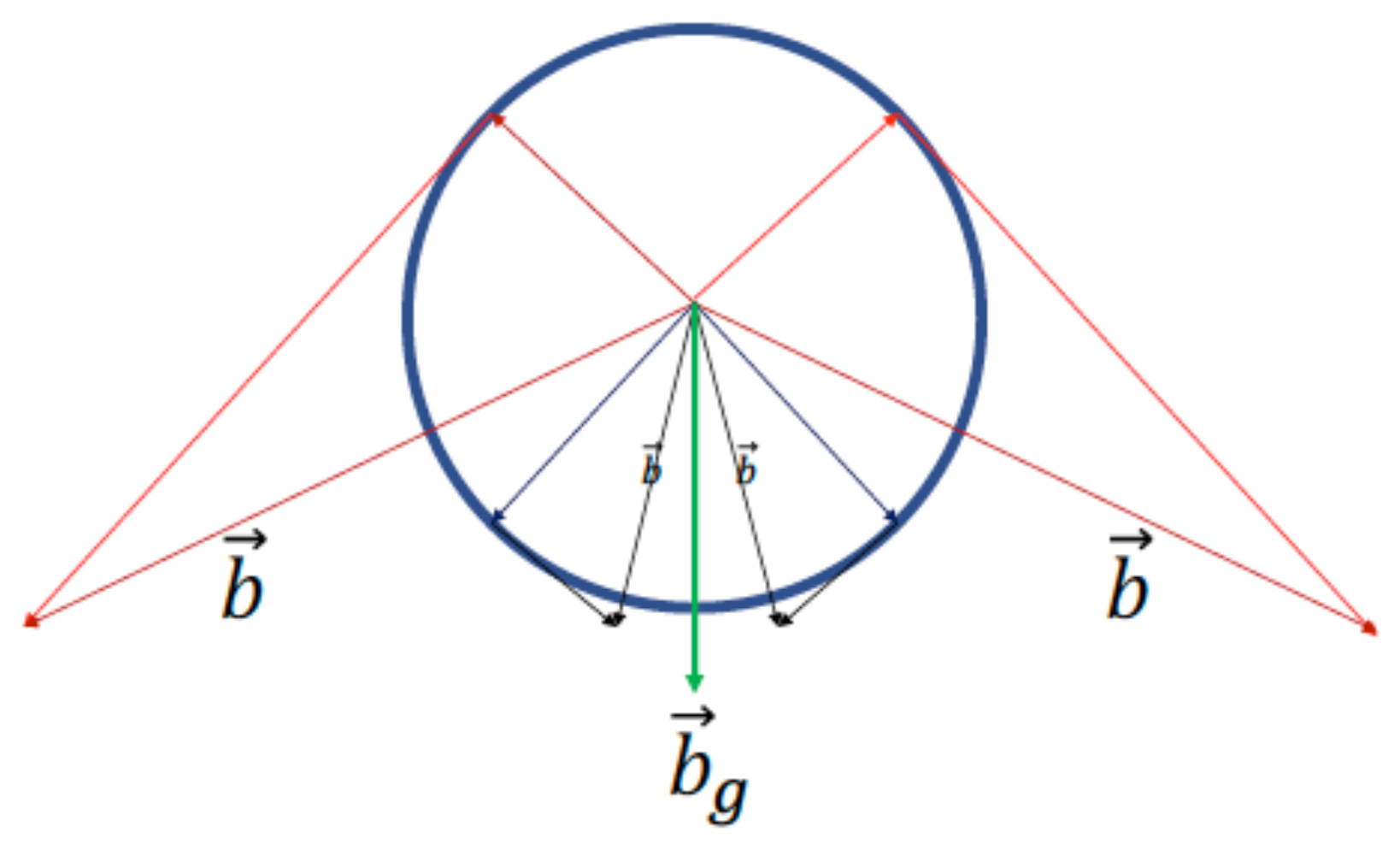
The geometry of the present problem is shown as a cross section of a tube in Figure 4 below.
Defining the following vector field,
W = t × b 1 2 × ρ 2 b · F T ,
S ( V ) W · n ^ d S   = V ( · W ) d V
= c 2 C f b ( r ) · d r
where n ^ = cos ( θ ) a and Stoke’s theorem has been used. Applying Stoke’s theorem to W , hence b . It is evident that the derivative of the circulation
d d t * C b · d r = C b t * · d r + C b · d b = C b t * · d r + C d | b | 2 / 2 .
The last integral in previous series of equalities is an integral of a perfect differential around a closed path and is therefore equal to zero. To use Stokes theorem for dynamic surfaces that change with time, it can be seen in Appendix B that using the Calculus of Moving Surfaces (CMS) [18,32], the only requirement is that the paraboloid surface considered here has the same boundary as a disk which is coincident to the boundary of the paraboloid. Under this observation, the boundary is stationary and so the surface integral over a dynamic surface can be reduced down to the line integral around the stationary path, and is thus equivalent to the path integral around a closed disk coincident with the mouth of the paraboloid. Therefore, the dynamic nature of the paraboloids studied in this paper is not a point of concern when applying Stokes Equation to obtain a line integral. Refer to Appendix A for general time derivatives of dynamic line integrals. Proceeding we obtain,
c 2 C f b ( r ) · T d s = C ( b t * + 1 2 ρ 2 b · F T ) · d r
where T is unit tangent vector to closed curve C and d s is arc length,
C ( c 2 f b ( r ) + b t * + 1 2 ρ 2 b · F T ) · d r = 0
The third term in the parenthesis in Equation (47) is integrated by parts for line integral and we obtain the following,
C ( c 2 f b ( r ) + b t * 1 2 F T · ( ρ 2 b ) ) · d r = 0
Parametrizing the circle as r = g ( θ ) in polar coordinates it can be proven that the line integral in Equation (48) is,
C ( c f b 1 2 + b 1 t * 1 2 F T 1 · ( ρ 2 b ) ) · d θ C ( c f b 2 2 + b 2 t * 1 2 F T 2 · ( ρ 2 b ) ) · d r = 0
The normal form of Green’s theorem can be used for the line integral in Equation (49), setting first,
M = b 1 t * + c b 1 b 1 r * + c b 2 b 1 θ r * 1 2 F T 1 · ( ρ 2 b )
N = b 2 t * + c b 1 b 2 r * + c b 2 b 2 θ r * 1 2 F T 2 · ( ρ 2 b )
The line integral in Equation (49) is equal to the following,
R M r + N θ d r d θ
where M and N are given by Equations (50) and (51) respectively and R is the open disk with boundary C. The gravity force F T 1 which includes multiplication by δ 3 (see Equations (13) and (14)), is expressed as follows,
F T = ϕ = g h = g ( b T S i ( α θ ) )
where S i is the sine integral, ϕ is a potential function, h is the negative height in the direction of the vector b g in Figure 4, T = 1 α is a time constant and g is gravity constant. Upon substitution of M and N into Equation (52) and further substitution of,
b 1 = 2 b 2 2 θ * sin ( α θ * ) r * 2 θ * 2 z * 2 × ( 2 θ * sin ( α θ * ) ( r * 2 + θ * 2 + z * 2 ) b 2 θ * + ( ( ( 4 r * + 1 ) θ * 2 + r * 2 + z * 2 ) sin ( α θ * ) + α θ * cos ( α θ * ) ( r * 2 + θ * 2 + z * 2 ) ) b 2 ) 1
gives us a very complicated pde to solve. However it is noteworthy to see that it is in fact separable in time t (Maple verification). The form is b 2 = U ( r * , θ * , z * ) H ( t * ) , where H ( t * ) is given by an ode,
d d t H t * = c 4 H t * 2

2.6. The Hunter-Saxton Equation

Vorticity is assumed to be in the form ω 3 = r * F ( θ * , z * , t * ) and in Equation (12) ρ a v g is taken to be negligible,
1 2 F T 2 · ( ρ 2 b ) = sin ( α θ ) α θ b 2 ( r * , θ * , z * , t * ) ( 2 α θ z 2 r γ 2 b 1 r * , θ * , z * , t * ln r sin α θ e ln r 2 δ 2 2 r δ 2 α θ z 2 r γ 2 b 1 r * , θ * , z * , t * γ sin α θ e ln r 2 δ 2 2 r 1 / 2 α θ z 2 r γ 2 r * b 1 r * , θ * , z * , t * sin α θ e ln r 2 δ 2 2 + 1 2 r ( α 2 θ z 2 r γ 2 b 2 r * , θ * , z * , t * cos α θ sin α θ 2 e ln r 2 δ 2 2 α z 2 r γ 2 b 2 r * , θ * , z * , t * sin α θ e ln r 2 δ 2 2 α θ z 2 r γ 2 θ * b 2 r * , θ * , z * , t * sin α θ e ln r 2 δ 2 2 ) )
Differentiate with respect to θ * , use Equation (54), substitute r * 2 θ * 2 z * 2 = 0 , so that we are on the circle at infinity and letting
b 2 r * , θ * , z * , t * = 1 / 2 F θ * , z * , t * r * 2 + θ * 2 + z * 2
A denotes the partial derivative b 2 θ * and B the azimuthal velocity b 2 . Letting the entire expression above for the derivative of F T 2 term with respect to θ be denoted by G and scaling G by dividing by 4 1 r * 3 z * 6 and taking the limit as z * approaches infinity gives,
r 2 γ 4 exp ( 2 ln ( r ) 2 δ 2 ) 2 θ * 2 sin ( α θ * ) 2 θ * 2 A 2 + 2 θ * B A B 2 cos α θ * 2 + 2 A B sin α θ * cos α θ * α θ * 2 + B 2 α 2 A 2 θ * 2 2 θ * B A + B 2
Substituting A = r * 2 A 2 and B = r * 2 B 2 where A 2 and B 2 are independent of r * as previously assumed due to vorticity being in this form as well(note we could have chosen A 2 , B 2 to be dependent on r * with similar results to follow since the form of ω 3 can be generalized), we obtain for Equation (57) in the limit as α 0 the following,
1 / 2 A 2 2 r γ 2 r 4 e ln r 2 δ 2 2
Finally taking the limit as α 0 , since γ = 1 1 δ and matching r * large for δ small (recall r = r * δ ), we obtain,
lim α 0 N θ * = A 2 2 2 = 1 2 ( b 2 θ * ) 2
It follows that the right hand side of N θ * is precisely 1 2 A 2 2 = 1 2 ( b 2 θ * ) 2 Using Equations (50)–(52) and integrating out r * parts and setting all constants to unity gives us a Hunter-Saxton-like equation at z * = on a perfect circle, that is,
θ * b 2 t * + b 2 b 2 θ * = 1 2 b 2 θ * 2
This equation is a Hunter-Saxton Equation that describes the evolution of the vorticity at the boundary of the tube. For very large regimes of the tube the fluid propagates as a Hunter-Saxton-like wave vortex along the boundary of the tube. It can be seen that b 1 = 0 and Equation (50) vanishes since F T 1 = 0 on the surface r * 2 θ * 2 z * 2 = 0 . To transform the Hunter-Saxton Equation into cartesian co-ordinates, we use the chain rule, with the following transformation,
r * = x 2 + y 2
θ * = tan 1 ( y / x )
To obtain the following evaluation of the derivatives:
b 2 x = b 2 r * r * x + b 2 θ * θ * x
b 2 y = b 2 r * r * y + b 2 θ * θ * y
By multiplying and subtracting(adding) x and y it can be shown that the following commutator relations hold,
b 2 θ * = x b 2 y y b 2 x b 2 r * = ( x 2 + y 2 ) 1 / 2 x b 2 x + y b 2 y
Upon further differentiation it can be shown that,
y 2 2 b 2 x 2 x 2 2 b 2 y 2 = y 4 x 4 ( x 2 + y 2 ) 3 / 2 b 2 r * + y 4 x 4 ( x 2 + y 2 ) 2 2 b 2 θ * 2 + 2 y 3 x + 2 x 3 y ( x 2 + y 2 ) 2 b 2 θ *
Using Equations (51) and (66) we obtain a pde which is separable in time and exhibits finite time blowup. The spatial part of the solution has been solved numerically. It is a simple exercise to show that waves at infinity occur showing that there is a vortex wave stucture there.

2.7. Non-Blowup Result

In Equation (58) it can be seen that if δ approaches infinity then this term approaches zero and we do not have a Hunter-Saxton equation. We have from Equations (12) and (16) that ρ will tend to zero and solutions will exist since only the viscosity term, pressure gradient and gravitational force terms will survive in Equation (16). To give the definition of density replacing Equations (10) and (11) for large δ , we write,
δ = θ ρ 1 ( r , θ , z , t ) + z z ρ 1 ( r , θ , z , t ) r ρ 1 ( r , θ , z , t ) r + ρ 1 ( r , θ , z , t ) ρ a v g
ρ 1 ( r , θ , z , t ) = ρ a v g + F ρ θ δ + ln ( r ) δ , z r 1 δ , t r
this would prove positive for the existence of regular solutions to the Incompressible Cylindrical Navier-Stokes equations. It is immediate that as δ , ρ 1 ρ a v g 0 in general.

2.8. Geometrical and Variational Analysis of the Hunter-Saxton Equation

The Hunter-Saxton equation mentioned above for b 2 ( θ * , t * ) contains geometrical significance. Primarily, to define the region upon which the Hunter-Saxton equation is prescribed in this case, let Σ R 2 represent an infinite cylindrical tube of radius R oriented along the z axis given by the following embedding in R 3 :
R = R cos θ * R sin θ * z , θ * [ 0 , 2 π ] , z ( , + ) , R R
For such a surface, a Lagrangian upon it would usually utilize L ( θ * , z ) but in this case it is sufficient to describe the Lagrangian as only dependent on θ * (and possibly time, t * ). The Lagrangian for the above formulation of the Hunter-Saxton Equation can be seen to be described by the following Surface Integral over the coordinate space of Σ denoted d R 2 = d θ * d z d t * of an Energy Density prescribed by L :
E = t i * t f * z ˜ z ˜ 0 2 π L b 2 , b 2 θ * , b 2 t * d θ * d z d t * , where L = 1 2 b 2 t * b 2 θ * + 1 2 b 2 b 2 θ * 2
Using Variational Calculus reproduces the following:
δ E = 0 L b 2 θ * L θ * b 2 t * L t b 2 δ b 2 = 0 2 b 2 θ * t * + θ * b 2 b 2 θ * = 1 2 b 2 θ * 2
which is the Hunter-Saxton Equation. The Lagrangian has difficulty being interpreted in the significance of the terms and how they would correspond to the geometry of the Surface it is defined on. If one considers the prototypical example of a cylindrical surface, a cylinder as prescribed above with Radius 1, it can be shown that the Lagrangian can be expressed in terms of CMS (Calculus of Moving Surfaces) objects on the surface Σ (the cylinder with radius 1) and expressing them through differential forms on b 2 = b 2 ( θ * , t ) by the following using the conventions of Ivancevic & Ivancevic [33]:
L = 1 2 S 1 ˙ b 2 , d ( Σ ) b 2 Σ + 1 2 b 2 ( R · N ) 2 d ( Σ ) b 2 , d ( Σ ) b 2 Σ
where · , · Σ is the inner product induced by the metric tensor on Σ , S 1 is the tangent vector to Σ in the θ direction (thus curves around the cylinder), ˙ is the Invariant Time Derivative from CMS [18] defined on Σ , d ( Σ ) is the differential of a function on Σ , ( · ) is the “sharp” notation taking 1-forms to their corresponding 1-vector through the metric tensor on Σ and N is the Normal on Σ . It can be shown that while this holds for Σ as defined, it also holds for small dynamic deformations of Σ . Defining the original Lagrangian for static surfaces as L 0 , if Σ is dynamic, the Lagrangian must be modified to the following:
L dynamic = L 0 + 1 2 V | | , d ( Σ ) b 2 Σ
where the Vector V | | denotes the tangential velocity of the Surface. Through integrating the Lagrangian over the surface, the additional term becomes converted into a line integral of b 2 V | | , n Σ Σ around the boundary of the cylindrical tube Σ where n Σ is the normal to the boundary in the z direction (since n Σ is perpendicular to both S 1 and N ). It can be noted that the normal to the boundary Σ is in the longitudinal direction whereas the tangential velocity strictly curves around the boundary of the tube and thus, the additional value vanishes. So:
t Σ L dynamic d Σ d t = t Σ L 0 d Σ d t
And thus produces the same variation. Therefore the Dynamic Nature of the Surface represents a gauge invariance in the Lagrangian which is fixed by the choice of the definition of the Invariant Time Derivative from CMS ˙ = t V | | · Σ which maps tensors to tensors on Σ whilst the surface is deforming. Defining the Inner Product Norm on Σ , ( · , · ) Σ = Σ · , · Σ d Σ , the Energy Density may be written in an alternate form:
E = t 1 2 S 1 ˙ b 2 , d ( Σ ) b 2 Σ + 1 2 b 2 R · N d ( Σ ) b 2 , b 2 R · N d ( Σ ) b 2 Σ d t
This may be simplified if we defined the 1-form A = d ( Σ ) b 2 and the 1-vector B = b 2 R · N A :
E = t 1 2 S 1 ˙ b 2 , A + 1 2 B , B d t
From this expression for the Energy Density, it is clear what the Variational Result which is the Hunter-Saxton Equation is communicating. The First integrand is a method to calculate the work that the Kinetic Energy of the moving vortex is contributing to the total energy, while the second integrand describes the internal energy produced by the friction against Σ induced by the Hunter Saxton vortex wave solution to the Variational Equation. If the Hodge Star operator ⋆ is defined on Σ , integrating the function over the surface, produces the following equivalent expression of the energy density using the adjoint nature of the Hodge Star to the inner product on Σ :
E = t Σ 1 2 ˙ b 2 d θ A + 1 2 B B d t
In this way, the Hunter Saxton Equation for the current setting (regarding fluid dynamics) with vorticity is intuitively obtained.

3. Analyzing Bio-Membranes under Steady and Dynamic Conditions

3.1. The Static Local Energy Density

A summary of the techniques used to analyze Biomembranes in steady regimes is presented here. This usually involves a notion of some sort of total energy density H . It can also be shown that Hamiltonian’s Variational Equations are tensorial if the Hamiltonian Density is tensorial itself [17]. Therefore, it can be easily seen why a Hamiltonian must be tensorial in its terms and over all scalar-valued.

3.1.1. Geometrical Preliminaries, Defining the Biomembrane Continuum

The analysis of the Local Energy Density is assumed to be on a Riemannian 2-Manifold Σ that is locally isomorphic to R 2 . Since it is a smooth Riemannian Manifold the manifold possesses a Vector Space at every point S ˜ Σ referred to as the Tangent Space at S ˜ , T S ˜ Σ with a dual co-tangent space T S ˜ * Σ . Tensors and Differential Forms at S ˜ Σ may be constructed as elements of the Tensor Product Spaces for a Tensor of rank ( p , q ) and as an element Exterior Product Space for a κ -Differential Form. The space of Tensors of rank ( p , q ) at S ˜ Σ , is denoted by T S ˜ ( p , q ) ( Σ ) and the space of κ -Forms constructed from the Exterior Product Spaces of either the Tangent Space or its dual are denoted as Λ S ˜ κ ( Σ ) or Λ S ˜ κ * ( Σ ) , respectively. They are constructed using the conventions from Ivancevic and Ivancevic [33] as such:
T S ˜ ( p , q ) ( Σ ) = m = 1 p T S ˜ Σ n = 1 q T S ˜ * Σ , Λ S ˜ κ ( Σ ) = m = 1 κ T S ˜ Σ , Λ S ˜ κ * ( Σ ) = n = 1 q T S ˜ * Σ
It can be seen that since the exterior product ∧ is a restriction of the tensor product ⊗, the space of Differential Forms from the tangent/co-tangent exterior product spaces is a subset of the space of Tensors such that Λ S ˜ κ ( Σ ) T S ˜ ( κ , 0 ) ( Σ ) and Λ S ˜ κ * ( Σ ) T S ˜ ( 0 , κ ) ( Σ ) . Also since the distinction is made between cotangent/tangent exterior product spaces and tensor product spaces, the musical isomorphisms are defined as ( · ) and ( · ) where ( · ) : Λ S ˜ κ * ( Σ ) Λ S ˜ κ ( Σ ) and ( · ) : Λ S ˜ κ ( Σ ) Λ S ˜ κ * ( Σ ) .
Accordingly, several geometric tensors and forms from Hodge-DeRham Theory and Differential Geometry may be defined on Σ such as Σ ’s Surface 2-Form d Σ Λ S ˜ 2 * ( Σ ) such that d Σ = 1 2 ε α β d S α d S β = det g S ˜ d S 1 d S 2 = Σ 1 . d Σ is the Unique Co-tangent 2-form defined on the Riemannian 2-Manifold Σ where ε α β is the components of the Levi-Civita cotangent 2-Form on Σ , det g S ˜ is the determinant of the Bilinear Symmetric (0,2)-Tensor g S ˜ ( · , · ) T S ˜ ( 0 , 2 ) ( Σ ) defined such that g S ˜ : T S ˜ Σ × T S ˜ Σ R at S ˜ Σ . This tensor is the Metric Tensor at S ˜ Σ and Σ is the Hodge Star Operator on Σ defined such that Σ : Λ S ˜ κ * ( Σ ) Λ S ˜ 2 κ ( Σ ) when operating on cotangent differential κ -forms or equivalently, Σ : Λ S ˜ κ ( Σ ) Λ S ˜ ( 2 κ ) * ( Σ ) when operating on tangent differential κ -forms.
Differential Operators may also be defined on Σ . The exterior derivative d ˜ : Λ S ˜ κ * ( Σ ) Λ S ˜ ( κ + 1 ) * ( Σ ) may be defined and the co-differential defined explicitly by δ ˜ = ( 1 ) Σ d ˜ Σ may also be defined on Σ . Since the exterior derivative operates strictly on cotangent κ -forms, the codifferential must necessarily act on tangent κ -forms given by A Λ S ˜ κ ( Σ ) and is generally defined as δ ˜ : Λ S ˜ κ ( Σ ) Λ S ˜ κ 1 ( Σ ) . Using these, the nominal Laplace-DeRham operator Δ ˜ : Λ S ˜ κ * ( Σ ) Λ S ˜ κ * ( Σ ) may be defined on a cotangent κ -form A Λ S ˜ κ * ( Σ ) explicitly by Δ ˜ A = d ˜ ( δ ˜ A ) + ( δ ˜ ( d ˜ A ) ) . Since the manifold is restricted to R 2 , the operator can only be defined on cotangent 0-forms and 1-forms. It can be shown that for a 0-form (a function) f, since δ ˜ f = 0 , then Δ ˜ f = Σ 2 f where Σ 2 is the Laplace-Beltrami Operator on Σ explicitly given by Σ 2 f = α α f where α = ι S a is the components of the covariant derivative on Σ using the notiation of ι A as the insertion operator on Σ . With these preliminary definitions, the Energy Density Action on Σ may be analyzed.

3.1.2. Introducing the Energy Density Action

On such a manifold, the Local Energy to be variated is typically formulated in the following general form:
S = Σ H ( S α β , B α β ) d Σ
where S α β are the components of the Metric Tensor g S ˜ ( · , · ) and B α β are the components of the curvature tensor on Σ . It is assumed that Σ = 0 and thus an analogue of Stokes Theorem which resembles Gauss’ Divergence Theorem on Σ holds for a 1-form A Λ S ˜ 1 ( Σ ) [18]:
Σ δ ˜ A d Σ = Σ ( ι A n Σ ) d ( Σ )
where n Σ T S ˜ ( 1 , 0 ) ( Σ ) is the surface vector which points outwards at the boundary Σ . Consequentially, as per this constraint, since Σ = 0 , then for all vectors V , Σ δ ˜ V d Σ = 0 for all Σ .

3.1.3. Properties and Requirements of the Hamiltonian and Its variation

The General Hamiltonian outlined in Equation (77) contains several interesting properties. First, it is important to note that so long as the Hamiltonian Energy Density H ( S α β , B α β ) is constructed from tensorial geometric objects on Σ , it will be invariant to changes of coordinates S α = S α ( S α ) . In addition, the Energy Density must be scalar-valued. Finally the Static Hamiltonian (as the name suggests) does not variate in time, in the sense that
d d t S = 0
As mentioned before, this indicates that this Hamiltonian Formulation is not suited for analyzing moving surfaces and if it is to be reformulated the new formulation must preserve all the scalar and invariant properties.
In component form, the Variation of the Energy Density with respect to the surface configuration R explicitly given by R = R + ϵ δ R results in the following form [24,34]:
δ S = d S [ R ] d ϵ ϵ = 0 = Σ α f α · δ R d Σ Σ β ( f β · δ R ) d Σ + Σ β H B α β N · α δ R d Σ
where f α is given by:
f α = β H B α β N H S α β + H B γ β B γ α + 2 H S α β S β
Its worth to note that this can be abbreviated using the Normal Calculus of Moving Surface outlined in Reference [35] by considering the vectors ξ μ = { S 1 , S 2 , N } as an orthonormal vector basis:
f α = f α μ ξ μ , f α μ = f α β = H S α β + H B γ β B γ α + 2 H S α β f α 3 = β H B α β

3.1.4. Stress Tensor

It can be noted that if the deformation δ R is allowed to correspond to constant translation, δ R = a , where α a = 0 , then the variation vanishes δ S = 0 . On a closed surface using the translation δ R = a , the variation reduces to:
δ S = a · Σ α f α d Σ = 0
This reflects that the quantity f α is conserved and is accordingly defined as the Stress for the system [25]. Accordingly, the tensor f α μ = f α · ξ μ is defined as the Stress Tensor of the System as per the Normal CMS Conventions outlined in Reference [35]. This makes physical intuitive sense; In equilibrium, the stress of the Surface should be conserved and the Surface’s according Equilibrium Configuration is determined by the Value of α f α .
In practice, only the Normal Projection of α f α is taken; this is because the tangential projection can be eliminated by a sufficient reparametrization of the Surface [25]. Therefore the equilibrium equation is as follows:
N · α f α = f α β B α β + α f α 3 = 0
Defining the symmetric (2,0) tensor f ˜ S = f α β S α S β , the curvature tensor by B ¯ = B α β S α S β and the 1-tensor f N = f α 3 S α , the conservation equation can be rewritten in terms of Hodge-Theory and also in a compressed conservation form through the Normal Calculus of Moving Surfaces [35] by the following:
ι B ¯ f ˜ S = δ ˜ f N , ξ μ 3 ˜ α f α μ = 0

3.1.5. The Dynamic Alternative to the Static Hamiltonian

As stated earlier, Variational Hamiltonian Equilibrium Configurations of Σ subject to H & have been used to derive Variational Shape Equations for Surfaces under the Canham-Helfrich Energy [36] (that is, H = H C H = 1 2 k c ( B α α c 0 ) 2 + λ ) or even simple Mean-Curvature squared Energy Densities (i.e., H = ( B α α ) 2 ) which have Biological Applications [18,37,38]. However these Energy Densities only permit the determination of equilibrium, static configurations of surfaces and do not allow for their Dynamic Modelling.
An apparent issue to ensuring the invariance of the Energy Density is shed light on by the recent field of CMS. By trying to incorporate terms which to capture the speed of the surface such the derivative with respect to time of the surface’s configuration V = t R or higher order acceleration terms such as t 2 R [32] and projections of the surface’s speed V · S α , as well as historical measurements of the speed such as R · V and 1 2 V · V [34,39], these terms violate of the Energy Density’s need to be invariant under coordinate transformations of dynamic membranes who’s transformations are time dependent S α ( t , S α ) [18,32,40]. This presents issues in deriving physically realistic quantities to describe the motion of membranes which are obtained by methods in classical mechanics. For this reason deriving scalar quantities which capture the motion of surfaces and are CMS-invariant is essential.

3.2. Invariant Scalars of Motion, Linear and Quadratic Invariants and Normal Speed Gradients

Before attempting to construct an Energy Density which is dynamic, scalars of motion which are CMS-invariant must be developed. Now the surface previously denoted by Σ must not be treated as Σ t indicating that it is in motion. All the Tensor Product Space and Exterior Product space constructions remain the same but are denoted as originating from Σ t . The jewel of CMS is the Invariant Time Derivative Operator which is defined as ˙ : T S ˜ ( p , q ) ( Σ t ) T S ˜ ( p , q ) ( Σ t ) and captures the time variance of the tensor operated on. It is defined on a scalar field Φ T S ˜ ( 0 , 0 ) ( Σ t ) by the following [18,32,40]:
˙ Φ = t Φ ι V ( d ˜ Φ )
where V Λ S ˜ 1 * ( Σ t ) is the surface speed defined as the speed of the 2-Manifold in R 3 , pulled back to the surface:
V = ( ι S α V ) d x a
It is important to notice how if the surface is not moving, V = 0 guarantees that ˙ = t [18]. Thus, ˙ only is a simple time derivative when acting on fields defined on Σ t which is not in motion or has an entirely normal motion of the form V = | V | N (as is the case with a uniformly expanding sphere/cylinder surface) [32]. Otherwise, the partial time derivative operator t does not produce tensors on Σ t , so objects which are constructed from the partial time derivative operator must either be eliminated from a hypothetical Dynamic Energy Density or must be treated in a CMS-manner to ensure the invariant-scalar nature of the Energy Density and therefore the ensuing Variational Conditions. The Invariant Time Derivative operator can also be extended to preserve the property that:
˙ : T S ˜ ( n , m ) ( Σ t ) T S ˜ ( n , m ) ( Σ t )
Ultimately we conclude that V = t R is not a tensor and thus cannot be used in an Energy Density. Therefore ˙ and its combination with other operators on Σ t must be used to identify invariant scalars of motion. It is known from CMS through the definition given in Equation (83), if R is the embedded configuration of the surface in R 3 , then ˙ R = C N , where the value C = V · N is referred to as the Normal Speed of Σ t . It is a Linear Invariant of Motion with respect to R , and so any function of C is also invariant and provides a manner of extending Invariants of Motion to higher-orders. As defined earlier, the Laplace-Beltrami Operator which is obtained from the Laplace-DeRham Operator Δ ˜ is Invariant itself. So this another linear invariant of motion is Δ ˜ C = δ ˜ ( d ˜ C ) . Therefore the two Linear Invariants of Motion I 1 and I 2 on Σ t are given by:
I 1 = C   ,   I 2 = Δ ˜ C = ( δ ˜ ( d ˜ C ) )
To continue searching for higher order invariants, the Commutator [ ˙ , α ] = ˙ α α ˙ can find use [32,35,40]. It is known that the commutator acts on Φ T S ˜ ( 0 , 0 ) ( Σ t ) as follows:
S α [ ˙ , α ] Φ = C S α B α β β Φ = ι C B ¯ ( d ˜ Φ )
Applying the commutator to R , we see that S α ˙ S α d ˜ ( C N ) = C B ¯ and since d ˜ N = B ¯ , then we see ˙ S α = N ι S α ( d ˜ C ) confirming the CMS identity that ˙ S α = N α C . It also proves that the 1-form d ˜ C = ( α C ) d S α is as expected invariant. Thus the norm of this norm may be obtained as | | ( d ˜ C ) | | 2 = g S ˜ ( ( d ˜ C ) , ( d ˜ C ) ) = S α β ( α C ) ( β C ) . Noting that ˙ ( N · N ) = 0 and ˙ ( S α · N ) , it can be confirmed with CMS that ˙ N = ( d ˜ C ) reaffirming the tensorial nature of d ˜ C .

Temporal Curvature Trace Tensors

Thus far, the commutator [ ˙ , α ] was restricted to 0-forms and it was shown that S α ( [ ˙ , α ] ) Φ = ι C B ¯ ( d ˜ Φ ) . Defining the cotangent 1-form operator Ξ ˜ : T S ˜ ( n , m ) ( Σ t ) T S ˜ ( n , m + 1 ) ( Σ t ) such that Ξ ˜ = d S α Ξ α where Ξ α = [ ˙ , α ] C B α β β , it is seen that Ξ ˜ Φ = 0 This operator can easily be extended to the Co-tangent Exterior Product Space to operate on 1-forms as Ξ ˜ : Λ S ˜ κ * ( Σ t ) Λ S ˜ ( κ + 1 ) * ( Σ t ) . This will be referred to as the Temporal Curvature Operator, as it can be seen that when applied to a section of the tangent space or cotangent space, the Temporal Curvature Tensor R ˙ T S ˜ ( 1 , 2 ) ( Σ t ) arises [32].
Ξ α ψ β = R ˙ α γ β ψ γ   ,   Ξ α ψ β = R ˙ α β γ ψ γ
As expected, Ξ α S α may be decomposed into a tangential and normal component. The normal projection confirms the linear nature of Δ ˜ C while the surface projection confirms the identity of the Temporal Curvature Tensor’s components R ˙ α β γ already established in other sources [32,40]:
R ˙ α β γ = 2 S γ δ B α [ β δ ] C
The Tensor admits three traces R ˙ γ β γ , R ˙ α γ γ , R ˙ α β γ S α β and by the antisymmetric structure within the Tensor, and the symmetric nature of the Metric Tensor, it can be easily seen that R ˙ α γ γ = 0 . Thus there are only two non-trivial traces in the Temporal Curvature Tensor. These will be denoted by a tangent 1-form and a cotangent 1-form T = T α S α = R ˙ α β γ S α β S γ & W ˜ = W α d S α = R ˙ γ α γ S α . It can be easily seen that the equivalence exists as T = W ˜ . Therefore, the two traces are related by an isomorphism. This originates in the identity of the Temporal Curvature Tensor that R ˙ β γ [ α S β ] γ = 0 . Thus we define the fundamental Temporal Curvature Trace 1-Form as
W ˜ = ι B ¯ ( d ˜ C ) Trace ( B ¯ ) d ˜ C
A natural Invariant of Motion which may be obtained from this is the 1-form’s norm given by g S ˜ ( W ˜ , W ˜ ) . Also since W ˜ Λ S ˜ 1 * ( Σ t ) , then another Linear Invariant of Motion is δ ˜ W ˜ .

3.3. Developing a CMS-Invariant Hamiltonian, Variating the Hamiltonian and Divergence Form of the Variation

Reflecting on all the CMS methods of measuring speeds on a membrane, a Dynamic Energy Density may be constructed effectively. The resulting form of the Hamiltonian Action chosen is as follows:
S = t Σ H ( S α β , B α β , C ) d Σ d t
For the purposes of this introduction so far, the specific form of H will remain non-given however this term will incorporate one of the Linear Invariant Scalars of Motion, C derived above. It is worthy to note that the Energy Density must have units of [ J / m 2 ] = [ N / m ] , so the Action has units of [ J · s ] . As stated earlier in the Static Case regarding Σ d Σ , the integral t d t ranges over the interval { t R | t 0 t t f } meaning t = { t 0 , t f } . Performing a Variation of the Hamiltonian much like the previous case [24], the total variation results in:
δ S = t Σ α f α ˙ H C N + H C C B α α N · δ R d Σ d t t Σ β f β · δ R H B α β N · α δ R d Σ d t + t d d t Σ H C N · δ R d Σ d t
where f α is the standard stress tensor from the previous Local Hamiltonian Energy Density [25]. This variation is fundamentally different from the Local Hamiltonian. It can be simplifed by defining the following linear operator δ ˜ t = ˙ C B α α defined by the relation:
d d t Σ Φ d Σ = Σ ˙ Φ C B α α Φ d Σ = Σ δ ˜ t Φ d Σ
In this case, the variation can be simplified to the following:
δ S = t Σ α f α δ ˜ t H C N · δ R d Σ d t + t Σ δ ˜ t H C N · δ R β f β · δ R H B α β N · α δ R d Σ d t
This equation may be put into a divergence form as outlined in Reference [24] by defining the Spatiotemporal Operator ˙ b where the latin lowercase index b takes on values { 1 , 2 , 3 } . In this case for b = 1..2 , ˙ b = ι S α d ˜ and for b = 3 , ˙ b = δ ˜ t . In this case, by defining in a similar manner the vector F b where for b = 1..2 , F b = f α and for b = 3 , F b = H C N , then the variation can be rephrased in the following manner:
δ S = t Σ ˙ b F b · δ R d Σ d t t Σ ˙ b ( F b · δ R ) d Σ d t + t Σ β H B α β N · α δ R d Σ d t

3.3.1. Defining a Surface Analog of ’Surface-Time’

In the definition of the Spatiotemporal Operator ˙ b , there is an negative sign in the third component ˙ 3 = δ ˜ t . To account for this negative sign, a Positive Spatiotemporal Operator ˙ b may be defined as ˙ c = σ b c ˙ c by defining the 3 × 3 Surface-Time Matrix using components from g S ˜ ( · , · ) :
σ b c = S 11 S 12 0 S 21 S 22 0 0 0 1
It is noteworthy to note that with this Matrix, defining its determinant as σ = det ( σ b c ) , then the following identity arises σ = det ( S α β ) . In this case, a 3 dimensional Surfacial-Temporal Space can be defined where the volume element in such a space is defined as d σ ˜ = σ d S 1 d S 2 d t . This is an interesting analogue to the Minkowski Space given in Elementary Physics Textbooks [34,41] And so an integral in this space is formulated as such:
σ ˜ d σ ˜ = t Σ d Σ d t
Therefore, the variation can be unformly expressed in this 3-dimensional Surface-Time:
δ S = σ ˜ σ b c ˙ b F c · δ R d σ ˜ σ ˜ σ b c ˙ b ( F c · δ R ) d σ ˜ + σ ˜ β H B α β N · α δ R d σ ˜
This 3-Dimensional Surface-Time shares several parallels with a 4-Dimensional Space Time. This has several applications:
  • The formulation of Surface-Time can be used for formulating and analyzing the geometry of a 2-Dimensional analogue of Space-Time [41].
  • The formulation of Surface-Time can also be used for introducing concepts of Relativity into moving Membranes, biological or otherwise [26,27].
  • Lastly, this formulation of Surface-Time can be used to describe a similar method for describing 4D Space-Time in a manner consistent with CMS [28].

3.3.2. Conservation Laws and the Stress Tensor

As with the Static Energy Density, if the deformation δ R = a , then the variation vanishes δ S = 0 [24,25]. On a closed surface using the translation δ R = a and assuming that the Surface Σ evaluated at t are equal ( that the Surface Geometry at the end of the deformation in time does not change from the beginning), then the Variation reduces to:
δ S = a · σ ˜ σ b c ˙ b F c d σ ˜
This reflect that the quantity F b is conserved and is defined as the Stress for the system. Accordingly, the tensor F b μ = ξ μ · F b , is defined as the Stress Tensor of the System in accordance with [35]. Just like the case with the Static Energy Density, the Stress of the Surface is Conserved and the Surface’s Dynamic Evolution is determined by the value of σ b c ˙ b F c .
Like the Local Static case, this paper will only examine the Normal Projection of the Stress’ Divergence. So therefore, the Dynamic Equilibrium Eqution is as follows:
N · σ b c ˙ b F c = 0

3.3.3. Specific Lagrangian: Quadratic Speed Lagrangian

It is well known that the Standard Energy Density for measuring the kinetic speed of a continuum (Surface or Volume) is given by [18,26,27,32,39]:
H = 1 2 ρ V · V
It is well shown by several sources that the Energy Density H = 1 / 2 ρ V · V is not tensorial on a time-deforming surface Σ t [18,32], due to the non-tensorial identity of V belonging to Σ t [40]. Thus, a modified CMS-invariant version is given by the Energy Density:
H = 1 2 ρ C 2
where ρ R represents the (assumed) homogeneous mass-density of the surface being analyzed; this definition can be made precise by using continuum methods outlined in Reference [39]. Using this Energy Density, it can be obtained that:
N · σ b c ˙ b F c = 0 ρ ˙ C 1 2 C 2 B α α = 0
This is the equation of motion for a surface which does not have any Energy Density on it except for its own motion. This is interesting in that the dynamics of the Surface are identical regardless of the homogeneous mass sensity, analogous to Newtonian Physics [42]. It is noteworthy that if C=0, the equation is satisfied. This can be satisfied by two ways:
  • If the surface is not moving, V = 0 .
  • If the surface is only moving tangentially V = V α S α .
These two solutions are somewhat trivial but can be easily imagined. For example, a sphere moving purely tangentially would be rolling along its surface. A sheet of paper moving tangentially would be it moving in its plane. It is intuitive why these would minimize the Energy Density. In addition, a non-trivial solution can be derived for the Sphere. A sphere which has a variable Radius, R = R ( t ) simplifies the equation to the following:
d 2 R d t 2 + 1 R d R d t 2 = 0
The solution to this equation is a straightforward one
R ( t ) = c 1 t + c 2
For the sphere, this result implies a linear increase in Area knowing that the area for a sphere is A = 4 π R 2 . Therefore a sphere which minimizes its kinetic energy density Hamlitonian will increase and decrease its Area linearly.
It is worthy to note that if the Hamiltonian was constrained by having a constant Volume and a Constant Surface Tension, the Action would have been modified to [24,25]:
S = t Σ H d Σ d t + μ t Σ d Σ d t + P t Ω d Ω d t
where Ω Represents the Volume the Surface Encloses. Obtaining the variational equations for this Action results in the following:
˙ C 1 2 C 2 B α α = P λ B α α
For a Sphere, the equation simplifies to the following equation:
d 2 R d t 2 + 1 R d R d t 2 2 λ R P = 0
The equation dictates the way that a Sphere will expand or contract in response to the Surface Tension μ , and Pressure on the Membrane P. In equilibrium with the surrounding, the Time Derivatives of the Radius Vanish and the equation results in the Young Laplace Equation [43]. In cases of non equilibrium, the equation results in showing how the surface will evolve to reach an equilibium by dictating the form of R ( t ) . The equilibrium solution for the Variational Equation may be found by setting C = 0 . This results in the following:
B α α = P λ
This is a compact way of notating the Young-Laplace Law.
In the case where λ = 0 , the Equilibrium Condition may be found by writing the Variational Equation out in full and observing where R ˙ = 0 ; this will yield Boyle’s Law ( P · Volume = constant ) [44] and if the converse is done, the equilibrium solution when P = 0 yields the Minimal Surface Equation where stationary solutions have B α α = 0 which is the famous solution to Plateau’s Minimal Surface Problem [18].

4. Work-Energy Theorem

The Form of the Lagrangian’s Variational Equations yields insights into the definition of the various Tensors derived; this framework allows for an analogue of the Work-Energy Theorem [45] to be formed on Σ . Under special circumstances, using an Energy Density of H = U ( C ) , the Variational Equation becomes
˙ d U d C d U d C U C C B α α = 0
This equation can be restated in the following form:
d d t Σ C d U d C U d Σ = 0
Therefore, the integrand is a constant of motion conserved on Σ t . Since the only Energy on a Surface is derived from U , the Equation can be interpreted as a form of a conservation of Kinetic Energy.
This can be generalized for an Energy Density H = G ( S α β , B α β ) + U ( C ) . Assuming the above energy density, the following results:
d d t Σ C d U d C U d Σ = Σ C N · α g α d Σ
where g α is the analogue of the f α stress tensor derived for the Energy Density G ( S α β , B α β ) . This equation outlines a relationship between the Kinetic Energy derived from U ( C ) , and the work exerted on the surface by C N · α g α . This is a form of the Work Energy Theorem for Surfaces [45]. Therefore the equation is interpreted as the following:
d d t Σ C d U d C U d Σ Rate of Change of Kinetic Energy = Σ C N · α g α d Σ Mechanical Power on Surface
It is worthy to note that normally, Mechanical Power of a moving body is calculated using its local continuum velocity v ( x ) [39]; the analogue of this work for Surfaces V ( S ) , has been shown by Grinfeld to be Non-tensorial for Surfaces [18,40]. However allowing the surface to move, and assuming a general Energy Density H ( S α β , B α β , C ) , results in the identification of the expression C N . This is the only component of the Ambient Surface Velocity V = C N + V α S α that is Tensorial; therefore it makes intuitive sense that this is the only component taken into account for Mechanical Power which is commonly notated in Continuum Mechanics literature as V v · b d V where b are all the body forces acting on a Body. The Dynamic Framework presented up to now supports some possible extensions.

5. Discussion

It has been earlier established in Section 2.8 that when modelling vorticity on a cylindrical tube, the evolution of the vorticity at the cylindrical surface Σ t can be obtained with the following Energy Density:
S = t 1 2 S 1 ˙ b 2 , d ˜ b 2 Σ + 1 2 b 2 R · N d ˜ b 2 , b 2 R · N d ˜ b 2 Σ d t
where ( A , B ) = Σ g S ˜ ( A , B ) d Σ . This Energy Density is seen to have the same stucture as the energy densities explored in Part II of this paper. When the Energy Density is variated with respect to b 2 (of Part I of paper), it results in the Hunter Saxton Equation. Defining the 1-form A = d ˜ b 2 , and the 1-vector B = b 2 R · N A :
S = t 1 2 S 1 ˙ b 2 , A + 1 2 B , B d t
Through the Energy Density, it can be seen that the vorticity b 2 interacts with Σ t through the Metric Tensor, and through the Normal. In this particular interaction, Σ t = Σ is Stationary and referred to the static cylindrical tube. In the case where Σ t is allowed to variate, the motion of a membrane with a Vorticity that is pre-prescribed at Σ t such as b 2 = ω ( R ( S α ) ) can be obtained through Variating the Energy Density with respect to R . In this case, the Vorticity would affect the surface which minimizes the Energy Caused by the interaction. This Minimization can be explored in the future when desiring to observe the motion of a dynamic membrane immersed in a fluid with Vorticity.

6. Conclusions

A reduction of the compressible Navier Stokes equations coupled to the continuity equation in cylindrical co-ordinates to a simpler problem has been shown. Dimensionless parameters were introduced whereby in the small limit case for both of these a method of solution is sought for in the tube. A wave pulse that travels downwards towards the wall exists in Figure 1 [46]. A Dirac Delta density pulse exists exactly at the entrance of the tube and the density decreases downstream in the tube due to frictional and pressure losses. The density is a Gaussian-like wave function with an exponential in time. The result is finite time blowup for the velocity in the azimuthal direction. The Hunter-Saxton equation is a special case appearing at z * = in θ * , t * . Future studies are required for parallel methods derived from this paper that can be applied to the problem of the Clay Institute for the Navier-Stokes Incompressible equations. The second objective of this paper was to develop a Variational Framework which is Dynamic in order to potentially model Biological Membranes. Several objectives were acheived:
  • The standard Variational Framework proposed in References [24,25] N · α f α = 0 was extended to Dynamic Surfaces by using the Calculus of Moving Surfaces (CMS) developed in Grinfeld’s Textbook [18].
  • Drawing, on previous extensions of CMS [32,35], several Invariants of Motion have been developed in this paper ( C , Q β α α β C , P β α α C β C ) which may be used in the Dynamic extension of the Hamiltonian; however, in this paper, the only invariant of motion considered was C for simplicity.
  • Finally, the Dynamic Framework was utilized under a general Hamiltonian Energy Density H = U ( C ) + G ( S α β , B α β ) to derive a constant of motion conserved with just the Normal Speed C contributing to the Hamiltonian Energy ( C U ( C ) U ( C ) ) and a general form of the Work-Energy Theorem that states that the rate of change of Kinetic Energy is equal to the Mechanical Power measured by C N · α g α = 0 on the Surface.

Author Contributions

For research T.E.M. and K.C.A.; methodology, T.E.M.; software, K.C.A.; validation, T.E.M., K.C.A.; formal analysis, T.E.M., K.C.A.; investigation, T.E.M.; resources, T.E.M.; data curation, T.E.M.; writing—original draft preparation, T.E.M.; writing—review and editing, T.E.M., K.C.A.; visualization, T.E.M., K.C.A.; supervision, T.E.M.; project administration, T.E.M.

Funding

This research received no external funding.

Conflicts of Interest

The authors declare no conflict of interest.

Nomenclature

u r * Radial component of velocity of fluid
u θ * Azimuthal component of velocity of fluid
u z * Axial component of velocity of fluid
r , r * Dimensional radial coordinates
θ , θ * Angular coordinate
z , z * Dimensional axial coordinate
ρ density of fluid
ρ 0 initial density of fluid- a constant
μ viscosity of fluid
Ppressure
F g r gravitational force in radial direction
F g θ gravitational force in azimuthal direction
F g z gravitational force in axial direction
δ nondimensional parameter
Φ non-blowup function
Ffunction of r, z and t
η arbitrary constant
F 4 ( t ) arbitrary function of t
F c ( t ) arbitrary function of t
Garbitrary function of spatial variables and t
α nondimensiional constant
ρ 1 part of the density function
A 1 constant part of blowup function
B 1 constant part of blowup function
e r * , e θ * , k unit vectors
L 1 composite vector
L 2 composite vector independent of δ
A velocity of fluid dependent on ρ
f inertial vector term
P pressure gradient
b velocity of fluid, b = L 2
f 2 norm squared
A B geometric product
A · B dot product
A × B cross product
D i v D i v = · ρ r * u θ * * 2 e r * + 2 ρ r * u r * * u θ * * e θ *
Ψ Ψ = 2 r * 2 2 u r * * θ * f · e θ * u θ * * θ * f · e r *
[ × b ] z * vorticity in z * direction
ω 3 vorticity in z * direction
ω 3-d vorticity vector
ω A 3-d angular velocity
| r | 2 | r | 2 = r * 2 + θ * 2 + z * 2
ϕ , ξ new coordinate system for cylindrical function z * 2 = r * 2 θ * 2
J α α surface Jacobian
x radial velocity null-surface
ξ m a x ξ m a x = tanh 1 ( z m a x / r m a x
ϕ m a x ϕ m a x = r 2 m a x z 2 m a x
r m a x r * value at z * = z m a x
ψ ψ = · 2 r * 2 2 u r * * θ * e θ * u θ * * θ * e r *
H H = ρ b · f ρ t
Y * Y * = · b
V ( μ ) V ( μ ) = μ + μ / 3
Ω Ω = ρ 2 H b · ( ρ ρ t )
proj f b vector projection of b onto f
U f ξ scalar projection for b
G G = 1 ρ 2 ρ t 2
β non-dimensional constant
B B = · b
Q Q = G b 2 t + G r b 2 b 2 θ + G r ρ b 2 ρ θ G r ρ 2 b 2 θ ρ 1 2 r 2 b 2 θ ( b 2 / ρ 2 ) θ
cconstant equal to 1 / δ
W vector field Equation (43)
n ^ normal vector to surface
Ssurface of control volume
Ccontour
T unit tangent vector to closed curve C
d s arclength
M , N differential operators acting on b 1 , b 2 respectively
Ropen disk with boundary C
ϕ potential function
ggravity constant
A , B A is b 2 θ * , B is b 2
A 2 , B 2 A = r * 2 A 2 , B = r * 2 B 2 , A 2 , B 2 independent of r *
x , y defined according to r * = x 2 + y 2 , θ * = tan 1 ( y / x )
Rradius of tube
L Lagrangian
E energy density
δ E variation of energy density
< · , · > Σ inner product
S 1 tangent vector to Σ
˙ Invariant time derivative
d ( Σ ) differential of a function on Σ
( · ) takes 1-forms to corresponding 1-vector through metric tensor on Σ
N normal on Σ
L 0 Lagrangian for static surfaces
L d y n a m i c Lagrangian for dynamic surfaces
V | | tangential velocity of the surface
Σ boundary of cylindrical tube
n Σ normal to boundary in z * direction
B B = b 2 R · N A
Hodge star operator
Exterior product
H Energy density
Σ Riemannian 2-Manifold
S ˜ point on Σ
T S ˜ Σ tangent space at S ˜
T S ˜ * Σ cotangent space
p , q rank of Tensor
T S ˜ ( p , q ) ( Σ ) space of Tensors of rank ( p , q ) at at S ˜ Σ
Λ S ˜ κ ( Σ ) space of κ -Forms constructed from the Exterior product space of tangent space
Λ S ˜ κ * ( Σ ) space of κ -Forms constructed from the Exterior product space of Dual of tangent space
tensor product
( · ) ( · ) : Λ S ˜ κ * ( Σ ) Λ S ˜ κ ( Σ )
( · ) ( · ) : Λ S ˜ κ ( Σ ) Λ S ˜ κ * ( Σ )
d Σ surface 2-form
ϵ α β components of Levi-Civita cotangent 2-form on Σ
g S ˜ Bilinear symmetric ( 0 , 2 ) Tensor, metric tensor at S ˜ Σ
d ˜ exterior derivative
δ ˜ co-differential
˜ nominal Laplace-DeRham operator
i A insertion operator on Σ
SLocal Energy
B α β components of curvature tensor on Σ
n Σ surface vector which points outwards at the boundary Σ
V vector
S α change of co-ordinates
R surface configuration
ξ ˜ μ orthonormal basis vectors
δ S variation of S
f α μ stress tensor of the system
α f α surface Equilibrium configuration
f ˜ s symmetric ( 2 , 0 ) Tensor
B ¯ curvature Tensor
f N 1-Tensor
H Canham-Helfrich Energy
B α α Mean-curvature density
Φ scalar field
CNormal speed of Σ t
[ , ] commutator
Ξ ˜ cotangent 1-form operator
R ˙ Temporal curvature tensor
R ˙ γ β γ trace of Tensor
T cotangent 1-form
δ ˜ W ˜ Linear Invariant of Motion

Appendix A. Time Derivative of Dynamic Line Integrals

Line Integrals are difficult to evaluate when they are restricted to the boundary Σ t of an open surface Σ t that is moving dynamically in time t; in several fields, but particularly in the Calculus of Moving Surfaces (CMS), Σ is usually parametrized by the vector function R Σ = R ( S , t ) , where S = S α = { S 1 , S 2 } represent the surface variables chosen to parametrize the Surface. The parametrization of Σ t is usually given by R λ = R ( U , t ) , where U = U ψ = { U 1 } represents the variable used to parametrize Σ t . Since the line is restricted to the boundary of the surface, R Σ is related to R λ through the composition R λ = R ( S ( U ) , t ) . In this case, S ( U ) = { S 1 ( U ) , S 2 ( U ) } refers to the relation of the surface variables to the line variable. Consequentially, derivatives with respect to time of these line integrals are difficult to evaluate as well. The line integral of a vector function F taken over the line variable interval U 1 [ a , b ] is simplified to:
Σ t F · d r = Σ t F · T d U = a b F · T | U | d U 1
where T is the unit tangent vector and U = U ϕ ψ is the metric tensor on Σ t ; all naming conventions on the line and surface are outlined in Reference [18]. Using CMS, the time derivative can pass inside the integral since it is an single integral taken over a variable independent of t. Thus, the following develops:
d d t Σ t F · d r = Σ t F t · T + F · ε ϕ U ϕ t d U
It is important to note that the partial derivative in the second term measures how much the tangent vector of the curve variates in time. This is evaluated further using tensors on the surface given in Reference [32]
d d t Σ t F · d r = Σ t F t + ( F · Γ ˙ α β S β ) S α · T d U
if the tensor Γ ˙ = Γ ˙ α β ( S α S β ) is defined, then the following is given for the time derivative of a line integral:
d d t Σ t F · d r = Σ t F t + Γ ˙ T F · d r

Appendix B. Using Stokes Theorem on Dynamic Surfaces & Special Cases

In general, Stokes Theorem is not typically able to be extended to open surfaces who are dynamic in time. It is stated earlier that
d d t Σ t F · d r = Σ t F t + Γ ˙ T F · d r
From CMS, it is known that an analogue of Gauss’ Divergence Theorem exists on open surfaces:
Σ n α S α · F d U = Σ α ( S α · F ) d Σ
Framing the above as a classic line integral results in the familiar form
Σ F · d r = Σ ε α β α ( F · S β ) d Σ = Σ S β ε α β · α F d Σ = Σ N × S α · α F d Σ
where α is the component representation of the covariant derivative on the surface Σ . Knowing that α F = ( S α · ) F , the above equation can be reduced to Stokes Equation, and so the equality can be viewed as an extension of Stokes Theorem to surfaces which are in motion. Utilizing the formula for the derivative of a line integral and substituting the right hand side in for the vector function, the following is obtained:
d d t Σ t F · d r = Σ t N × S α · α F t + Γ ˙ T F d Σ
Again recalling that α F = ( S α · ) F , the surface integral can be broken up into two surface integrals:
d d t Σ t F · d r = Σ t × F t · d Σ ¯ + Σ t N × S α · α Γ ˙ ˜ T F d Σ
This is in general the relationship between the derivative of a line integral and the equivalent surface integral assuming the surface is in motion. It is worth noting as expected that the Tensor which captures the speed of the surface (and therefore the speed of the boundary), Γ ˙ is included in the surface integral as expected. A special case worth noting is that if in fact the speed on the surface evaluated at the boundary is stationary (i.e., a surface deforming with a fixed boundary Σ t = Σ ), then it can be seen that Γ ˙ = 0 and thus the equation reduces to the desired result:
d d t Σ F · d r = Σ t × F t · d Σ ¯ , Γ ˙ Σ = 0
where the time derivative is taken over a stationary path Σ , but the surface integral is taken over a dynamic surface Σ t . Therefore Stokes Theorem is valid for a surface that is moving in time, provided that the boundary is stationary. This is useful to evaluate integrals which are in motion as well.

Appendix C. Specific Density Formulation According to Theorem 1

Using Theorem 1 it can be shown readily that a specific density form is as follows,
A = 0.02350111407 + 1.057985743 i r Y i r 1.0 i J i r r J 1 + i i r + 0.02350111407 1.057985743 i r Y i r + 1.0 i J i r r Y 1 + i i r + 1.057985743 0.02350111407 i r J i i r + 1.057985743 + 0.02350111407 i r Y i i r Y 1 + i r + 1.0 r Y i i r + r J i i r J 1 + i r + 1.057985743 + 0.02350111407 i Y i r 1.0 J i r J i i r + 1.057985743 0.023501114 i Y i r + J i r Y i i r
B = 2.0 J i r r J i i r 1.0 Y i i r
The density can be taken as,
ρ = ( B / A ) exp ( α θ ) exp ( c t )
In the above expression for A , B , we have complex order and argument Bessel functions.

References

  1. Pereira, L.M.; Perez Guerrero, J.S.; Cotta, R.M. Integral transformation of the Navier Stokes equations in cylindrical geometry. Comput. Mech. 1998, 21, 60–70. [Google Scholar] [CrossRef]
  2. Cai, R. Some Explicit analytical solutions of unsteady compressible flow. Trans. ASME J. Fluids Eng. 1998, 120, 760–764. [Google Scholar] [CrossRef]
  3. MacCormack, R.W. A Numerical Method for Solving the Equations of Compressible Viscous Flow. AIAA J. 1982, 20, 1275–1281. [Google Scholar] [CrossRef] [Green Version]
  4. Piquet, A.; Zebiri, B.; Hadjadj, A.; Safdari Shadloo, M. A parallel high-order compressible flows solver with domain decomposition method in the generalized curvilinear coordinates system. Int. J. Numer. Methods Heat Fluid Flow 2019. [Google Scholar] [CrossRef]
  5. Taylor, C.; Hughes, T.G. Finite element programming of the Navier Stokes equations. Z. Angew. Math. Mech. 1983. [Google Scholar] [CrossRef]
  6. Feistauer, M.; Felcman, J.; Straskraba, I. Mathematical and Computational Methods for Compressible Flow; Clarendon Press-Oxford Science Publications: Oxford, UK, 2003. [Google Scholar]
  7. Vadasz, P. Rendering the Navier-Stokes equations for a compressible fluid into the Schrödinger Equation for quantum mechanics. Fluids 2016, 1, 18. [Google Scholar] [CrossRef]
  8. Ebin, D.G. Motion of a Slightly Compressible Fluid. Proc. Natl. Acad. Sci. USA 1975, 72, 539–542. [Google Scholar] [CrossRef] [Green Version]
  9. Wang, Y.L.; Longwell, P.A. Laminar flow in the inlet section of parallel plates. AIChE J. 1964, 10, 323–330. [Google Scholar] [CrossRef]
  10. Harraga, H.; Yebdri, M. Attractors for a nonautonomous reaction-diffusion equation with delay. Appl. Math. Nonlinear Sci. 2018, 3, 127–150. [Google Scholar] [CrossRef] [Green Version]
  11. Vajravelu, K.; Li, R.; Dewasurendra, M.; Benarroch, J.; Ossi, N.; Zhang, Y.; Sammarco, M.; Prasad, K.V. Effects of second-order slip and drag reduction in boundary layer flows. Appl. Math. Nonlinear Sci. 2018, 3, 291–302. [Google Scholar] [CrossRef] [Green Version]
  12. Bazhenov, V.A.; Pogorelova, O.S.; Postnikova, T.G. Intermittent transition to chaos in vibroimpact system. Appl. Math. Nonlinear Sci. 2018, 3, 475–486. [Google Scholar] [CrossRef] [Green Version]
  13. Gibbs, J.W.; Wilson, E.B. Vector Analysis; Charles Scribner’s Sons: New York, NY, USA, 1901. [Google Scholar]
  14. Muralidhar, K. Algebra of complex vectors and applications in electromagnetic theory and quantum mechanics. Mathematics 2015, 3, 781–842. [Google Scholar] [CrossRef]
  15. Muller, C. Foundations of the Mathematical Theory of Electromagnetic Waves; Springer: New York, NY, USA, 1969; pp. 339–341. [Google Scholar]
  16. Lindell, I.V. Complex vector algebra in electromagnetics. Int. J. Electr. Eng. Educ. 1983, 20, 33–47. [Google Scholar] [CrossRef]
  17. Nelson, D.R. Statistical Mechanics of Membranes and Surfaces, 2nd ed.; World Scientific: London, UK, 2004. [Google Scholar]
  18. Grinfeld, P. Introduction to Tensor Analysis and the Calculus of Moving Surfaces; Springer: New York, NY, USA, 2010. [Google Scholar]
  19. McMullin, M.F. The molecular basis of disorders of the red cell membrane. J. Clin. Pathol. 1999, 52, 245. [Google Scholar] [CrossRef] [PubMed]
  20. Iolascon, A.; del Giudice Miraglia, E.; Camaschella, C. Molecular pathology of inherited erythrocyte membrane disorders: hereditary spherocytosis and elliptocytosis. Haematologica 1992, 77, 60–72. [Google Scholar] [PubMed]
  21. Falk, G.; Fatt, P. Linear electrical properties of striated muscle fibres observed with intracellular electrodes. Proc. R. Soc. Lond. Biol. 1964, 160, 69–123. [Google Scholar]
  22. Henszen, M.M.; Weske, M.; Schwarz, S.; Haest, C.W.; Deuticke, B. Electric field pulses induce reversible shape transformation of human erythrocytes. Mol. Membr. Biol. 1997, 14, 195–204. [Google Scholar] [CrossRef]
  23. Durney, C.H.; Johnson, C.C.; Barber, P.W.; Massoudi, H.; Iskander, M.F.; Allen, S.J.; Mitchell, J.C. Descriptive summary: Radiofrequency radiation dosimetry handbook-2nd Edition. Radio Sci. 1979, 14, 5–7. [Google Scholar] [CrossRef]
  24. Guven, J. Laplace pressure as a surface stress in fluid vesicles. J. Phys. A Math. Gen. 2006, 39, 3771–3785. [Google Scholar] [CrossRef] [Green Version]
  25. Capovilla, R.; Guven, J. Stresses in lipid membranes. J. Phys. A Math. Gen. 2002, 35, 6233–6247. [Google Scholar] [CrossRef]
  26. Svintradze, D.V. Two dimensional surface dynamics. arXiv 2018, arXiv:1802.07166. [Google Scholar]
  27. Svintradze, D.V. Micelles Hydrodynamics. arXiv 2016, arXiv:1608.01491. [Google Scholar]
  28. Svintradze, D.V. Moving manifolds in electromagnetic fields. Front. Phys. 2017, 5, 37. [Google Scholar] [CrossRef]
  29. Moschandreou, T. A Method of Solving Compressible Navier Stokes Equations in Cylindrical Coordinates Using Geometric Algebra. Mathematics 2019, 7, 126. [Google Scholar] [CrossRef]
  30. Doran, C.; Lasenby, A. Geometric Algebra for Physicists; Cambridge University Press: Cambridge, UK, 2003. [Google Scholar]
  31. Beale, J.T.; Kato, T.; Majda, A. Remarks on the Breakdown of Smooth Solutions for the 3-D Euler Equations. Commun. Math. Phys. 1984, 94, 61–66. [Google Scholar] [CrossRef]
  32. Afas, K.C. Extending the Calculus of Moving Surfaces to Higher Orders. arxiv 2018, arXiv:1806.02335. [Google Scholar]
  33. Ivancevic, V.G.; Ivancevic, T.T. Undergraduate Lecture Notes in DeRham-Hodge Theory. arxiv 2011, arXiv:0807.4991v4. [Google Scholar]
  34. Deriglazov, A. Classical Mechanics; Springer: Berlin, Germany, 2010. [Google Scholar]
  35. Afas, K.C. Normal Calculus on Moving Surfaces. Preprints 2018. [Google Scholar] [CrossRef]
  36. Zhong-Can, O.-Y.; Helfrich, W. Instability and deformation of a spherical vesicle by pressure. Phys. Rev. Lett. 1987, 59, 2486–2488. [Google Scholar] [CrossRef]
  37. Bryant, R.L. A duality theorem for willmore surfaces. J. Differ. Geom. 1984, 20, 23–53. [Google Scholar] [CrossRef]
  38. Toda, M.; Athukoralage, B. Geometry of Biological Membranes and Willmore Energy; Simos, T., Psihoyios, G., Tsitouras, C., Eds.; American Institute of Physics Conference Series; American Institute of Physics Conference: New York, NY, USA, 2013; Volume 1558, pp. 883–886. [Google Scholar]
  39. Gonzalez, O.; Stuart, A.M. Kinematics; Cambridge Texts in Applied Mathematics; Cambridge University Press: Cambridge, UK, 2008; pp. 112–166. [Google Scholar]
  40. Grinfeld, P. A better calculus of moving surfaces. J. Geom. Symmetry Phys. 2012, 26, 61–69. [Google Scholar]
  41. Misner, C.W.; Thorne, K.S.; Wheeler, J.A. Gravitation, 1st ed.; Physics Series; W. H. Freeman: San Fransisco, CA, USA, 1973. [Google Scholar]
  42. Holton, G.; Brush, S.G.; Evans, J. Physics, the Human Adventure from Copernicus to Einstein and Beyond. Phys. Today 2001, 54, 69. [Google Scholar]
  43. Roura, P. Thermodynamic derivations of the mechanical equilibrium conditions for fluid surfaces: Young’s and Laplace’s equations. Am. J. Phys. 2005, 73, 1139–1147. [Google Scholar] [CrossRef]
  44. Laugier, A.; Garai, J. Derivation of the ideal gas law. J. Chem. Educ. 2007, 84, 1832. [Google Scholar] [CrossRef]
  45. Halliday, D.; Resnick, R.; Walker, J. Fundamentals of Physics, 9th ed.; Wiley: New York, NY, USA, 2011. [Google Scholar]
  46. Morisson, F.A. Compressible Fluids; Michigan Technological University: Houghton, MI, USA, 2004; pp. 94–98. [Google Scholar]
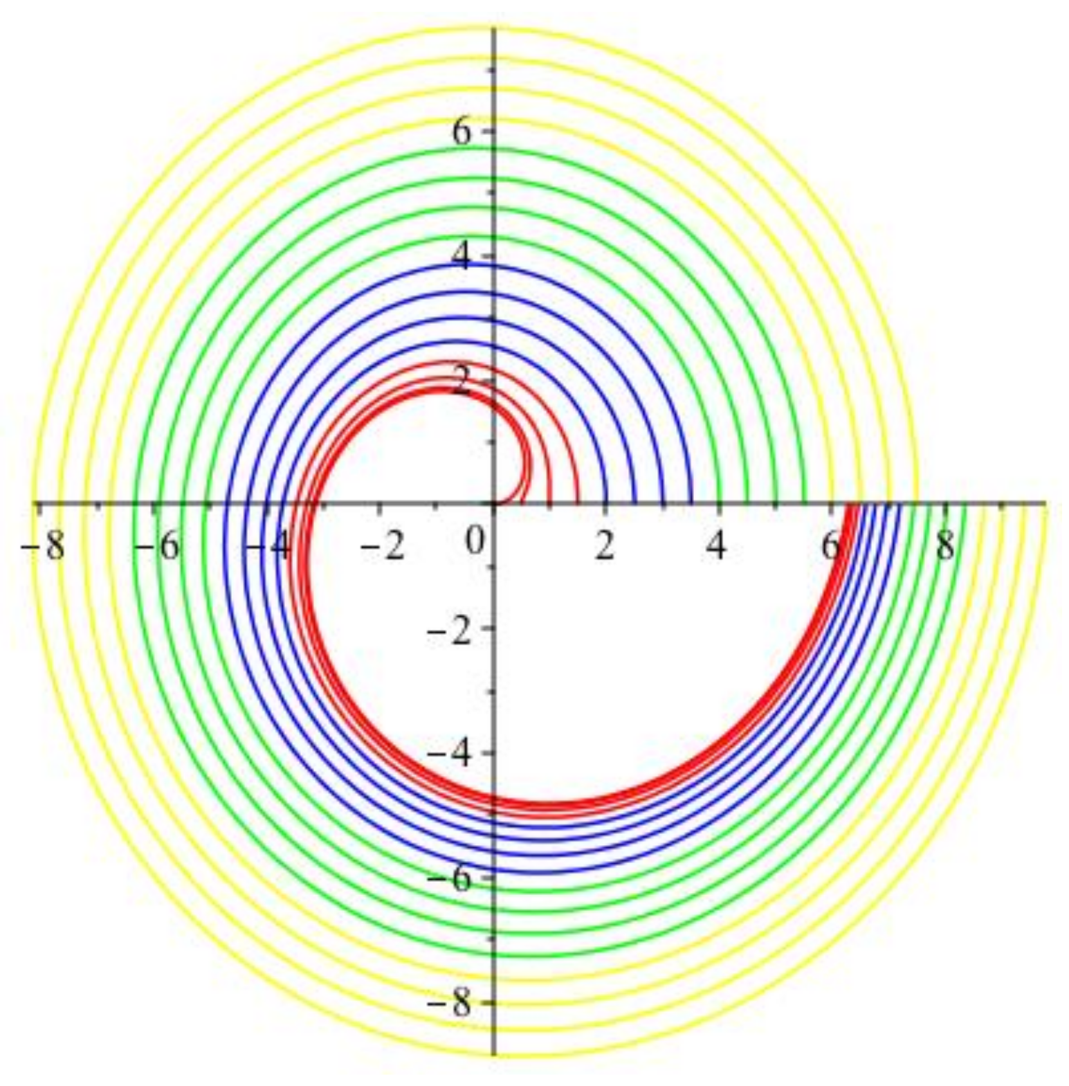
Figure 1. Plot of contours obtained by using Maple 2019 software; red corresponds to the values z = 0, 0.5, 1, 1.5, blue to the values z = 2, 2.5, 3, 3.5, green to the values z = 4, 4.5, 5, 5.5 and yellow to the values z = 6, 6.5, 7, 7.5. It can be observed that as z approaches infinity a perfect circular contour is formed.
Mathematics 07 01060 g001
Figure 2. Contour plot obtained using Maple 2019 software, taking contours at various z values up to z = 20.
Mathematics 07 01060 g002
Figure 3. A cylinder in green with embedded surface r = θ 2 z 2 in red obtained using Maple 2019 software.
Mathematics 07 01060 g003
Figure 4. Vector b g which is pointing in the direction of increasing gravitational force. The right angle triangles show vector addition as expressed by solution, L 2 = b = u r * * e r * + u θ * * e θ * .
Mathematics 07 01060 g004