Any object moving through a fluid will experience an aerodynamic drag that is produced by both pressure and shear forces acting on its surface.
where
is the total drag,
is the pressure drag, and
is the friction drag. Pressure drag is strongly dependent on the shape or form of the object; friction drag is a function of the wall shear stress, which is affected by surface roughness and the Reynolds number [
27]. The drag coefficient is defined by the following equations:
where
is the frontal area, which is the cross-sectional area of the pod calculated by
. Thus, in this study, the reference area in Equations (16)–(18) is approximately 7.065 m
2.
is the reference density of air in the tube pressure and temperature of 300 K.
is the pod speed.
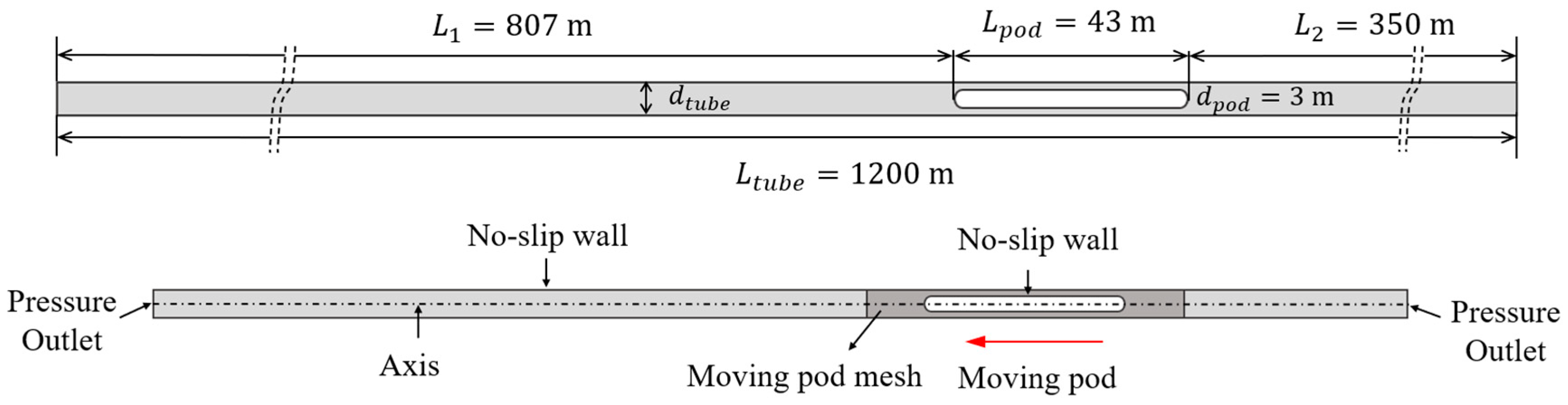
This study mainly focuses on the influence of various parameters on the aerodynamic drag. The amplitude and speed of pressure waves are also presented. The main variables considered here include BR, operating pod speed, internal tube pressure, and pod length. Owing to a fixed cross-sectional area of the pod, the variation in BR is obtained by changing the tube diameter to 6 m for BR = 0.25 (5 m for BR = 0.36). The pod speed was varied from 100 to 350 m/s in intervals of 50 m/s, in other words, 100, 150, 200, 250, 300, 350 m/s. For investigating the flows near the critical Mach number, two more pod speeds were chosen, namely, 225 and 275 m/s. With changing tube pressure, the pod speed of 300 m/s was selected to evaluate four different tube pressures, namely, 101.325, 500, 750, and 1013.25 Pa under a BR of 0.36 and a pod length of 43 m. The Hyperloop Alpha documents used a pod length of 43 m to carry 28 passengers per trip. To investigate the effect of pod length on drag coefficient, the case of = 43 m and two reference cases and were selected.
3.1. Effect of Blockage Ratio and Pod Speed
As indicated in
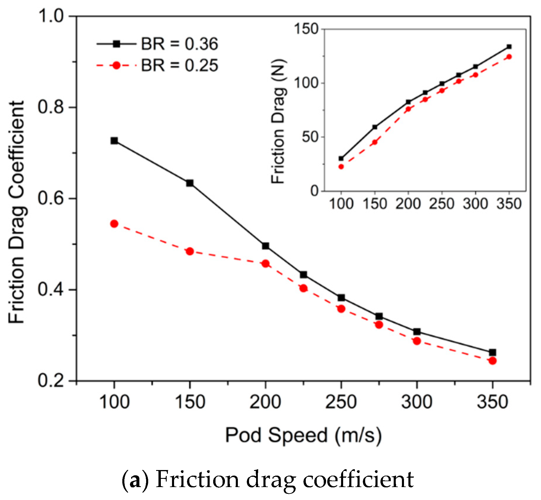
Figure 6, the changes of friction and pressure drag coefficient vary by two values of BR from
of 100 to 350 m/s. The variation of friction and pressure drag is given in insets. Besides,
Figure A2 and
Figure A3 (
Appendix B) also show the variation of friction and pressure drag coefficients on
and Mach number. In
Figure 6, at the same
, the friction drag coefficient
and the pressure drag coefficient
increase as the BR increases. When the BR is higher, the area where the flow passes through decreases. Thus, the flow becomes harder to bypass, increasing the friction drag generated along the pod surface and resulting in
increases as BR increases (
Figure 6a). It should be noted that from the
of 200 m/s, the effect of BR on
reduces due to severe choking.
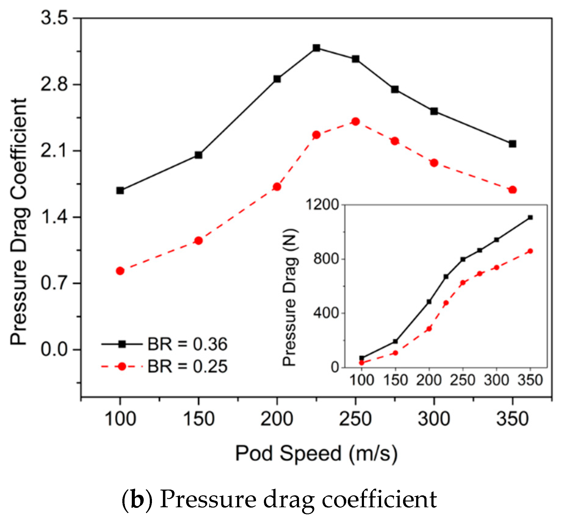
The change in pressure drag depends on the pressure difference between the nose and tail of the pod. With increasing BR, the air becomes more compressible, which increases the pressure magnitude along the pod surface as well as the pressure difference between the nose and the tail, resulting in an increase in pressure drag; hence
increases. With increasing
, pressure and friction drag increase continuously and significantly. Unlike drag, the drag coefficients witness different tendencies. As shown in
Figure 6b, at BR = 0.36,
increases and reaches the maximum at a
of 225 m/s. Subsequently, it exhibits a continuous drop. By contrast,
presents an incessant decrease with the increment of
. The results show tendencies similar with those in previous literature [
5,
11,
23,
28]. Note that, at lower values of BR, the maximum value of
changes. In this study, at BR = 0.25,
reaches a maximum at a
of 250 m/s, which will be compared later with BR = 0.36.
Generally, aerodynamic drag is composed of pressure and friction drags. Unlike in the open air, the Hyperloop pod moves in a tunnel, experiencing more aerodynamic drag owing to the increase in pressure generated by its interaction with the tunnel walls [
29]. At higher speed, there will be higher pressure. When the pod passes through the tube at a high speed, a high-pressure region is formed in the front of the pod nose. Meanwhile, the pod tail experiences an increase in the velocity of flow and reduces the pressure behind the pod. This phenomenon is similar to the behavior of flow through a convergent–divergent nozzle and results in a greater pressure difference between the nose and the tail of the pod; this leads to an increase in the pressure drag. Besides, the low pressure in the tube reduces the friction drag in the Hyperloop system. Hence, in the pod–tube system, pressure drag is more dominant than friction drag.
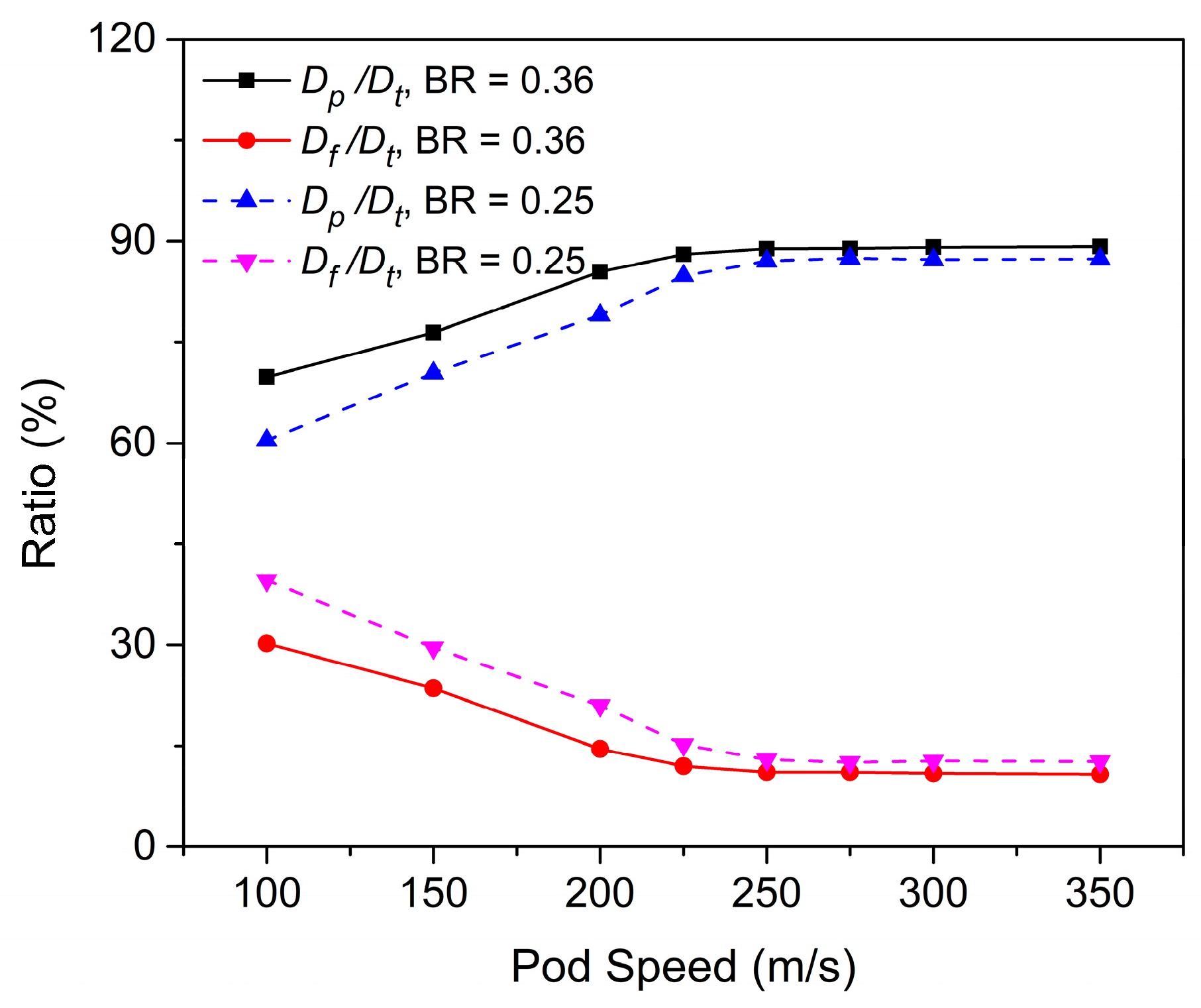
To evaluate the portions of pressure and friction drag in the total drag, the ratios of the two drag components to the total drag are shown in
Figure 7. At BR = 0.36 and
= 100 m/s, pressure drag dominates the total drag by 70%; the remaining percentage belongs to friction drag. However, pressure drag becomes more dominant as
increases owing to the increase of the difference in pressure at the nose and tail; the friction drag does not change much. This results in the pressure drag becoming more dominant at
of 350 m/s, making up 89.2% of the total drag, whereas friction drag only makes up 10.8%. The portion of
decreases with reducing BR, whereas the portion of
increases. This is because the effect of BR on the pressure drag is much higher than on friction drag. As BR reduces from 0.36 to 0.25, and at
= 100 m/s, pressure drag decreases by more than 50%, whereas the friction decreases by approximately 25%. This gap is greater at
= 350 m/s, where the margins of decrease for pressure drag and friction drag are 22.4% and 6.9%, respectively. Note that the ratios of the pressure and friction drags to the total drag begin to converge from a
of 250 m/s.
The pressure contours in
Figure 8 show that the pressure in front of the pod increases with increase of BR.
Figure 8d,e,j,k reveals shockwaves at the rear end of the pod; these shockwaves are made of normal and oblique shockwaves generated by the interaction and reflection of pressure waves between the tube walls and pod surface. When the local flow velocity exceeds the speed of sound, the interaction and connection of the airflow and pod surface create oblique shockwaves [
28]. With increasing
, the shockwaves become more distinct, expand backward, are reflected by the upper and lower walls of the tube [
16], and are then weakened downstream owing to the friction of the airflow. This oblique shockwave intensifies the airflow pressure at the rear end of the pod, resulting in an abrupt pressure increase at the tail (
Figure 9a). Note that at lower BR, the formation of oblique shockwaves is delayed. The existence of shockwaves affects the variation of
. In this study, shockwaves are noticed before the
where
is maximized. At BR = 0.25, the shockwave structure can be observed from a
of 225 m/s (
Figure 8c), and from 200 m/s at BR = 0.36 (
Figure 8h). The previous study conducted by Kim et al. (2011) [
12] also indicated that the impact of shockwaves was reduced when BR was reduced. Hence, to limit the effect of shockwaves, we considered the influence of BR [
8,
12].
With increasing BR, the percentage of pressure drag to total drag increases. To explain this phenomenon,
Figure 9a illustrates the pressure difference between the nose and the tail of the pod, which is one of the factors affecting pressure drag. As the
increases, the pressure at the nose increases significantly, which is in contrast with the slight decrease in pressure at the tail. This difference causes a substantial increase in the pressure difference between the nose and the tail, resulting in a sharp increase in the pressure drag. This pressure difference in turn increases with the increase of
and BR. At the same
, the pressure at the nose with BR = 0.36 is higher than in the case when BR = 0.25 because of the generation of stronger compression waves. Otherwise, the tail pressure experiences a smaller pressure drop when the BR is smaller, because the air in the larger tube expands easily [
11,
12,
30].
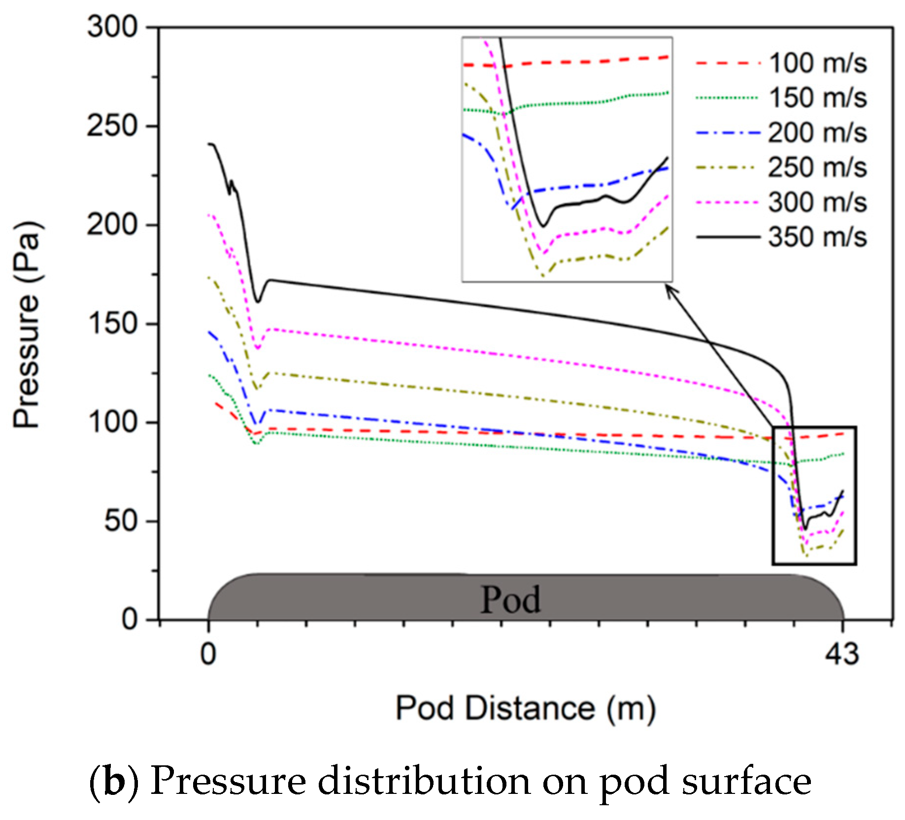
Figure 9b illustrates the pressure variation across the pod surface. There is a sudden increase in the pressure at the tail from a
of 250 m/s owing to the formation of strong oblique shockwaves. A noticeable increase in the surface pressure occurs from 200 to 250 m/s, where the choking flow becomes severe. Note that, although an increment in the surface pressure was observed from 100 to 250 m/s, the pressure magnitude at the tail exhibited a considerable drop owing to the stronger flow expansion with increasing
. As oblique shockwaves appear at the tail from a
of 250 m/s, the tail pressure slightly increases.
3.3. Effect of Pod Length
This section investigates the effect of pod length on the drag coefficient. Three cases were examined based on the reference pod length from the Hyperloop Alpha documents. The pod length of
= 43 m was used as a reference case to analyze the two cases of
and
.
Figure 11 examines the effect of pod length on the drag coefficient and the ratios of pressure and friction drags to the total drag.
As indicated in
Figure 11a, the pod length does not have a significant effect on
, whereas it leads to a considerable increase in
. The variation of drag coefficient with respect to pod length follows a similar trend as the variation of drag force. The variation of drag force with pod length is presented in the sub-figure. Friction drag is generally generated along the pod surface; hence, when increasing the pod length, friction drag increases nearly proportionally. The drag acting on a shorter pod mostly depends on the pressure drag. The increase of pressure drag is mostly affected by the pressure distribution in the front and rear of the pod; hence, the extension of pod length has little effect on the pressure drag. Nevertheless, friction drag is significantly altered because it is strongly dependent on the surface area.
is nearly doubled when doubling the pod length, whereas the increase of
is negligible. Consequently, with the increase of pod length, the increase of total drag is mostly because of the increase in friction drag. To further explain the statement, the ratios of the pressure and friction drags to the total drag are presented in
Figure 11b. With
, the ratio of pressure drag to friction drag is approximately 12:1. However, with
, this ratio reduces to 5:1.
3.4. Pressure Wave Propagation
The speed of sound in gases is dependent on the temperature. Under the assumption of isentropic flow, the speed of sound is estimated by
.
and
are the ratios of specific heats and the individual gas constant with the assigned values of 1.4 and 287.058 J/kg.K, respectively; at an air temperature of 300 K,
= 347.1 m/s. Under atmosphere pressure and linear wave assumption, the pressure waves propagate at the speed of sound [
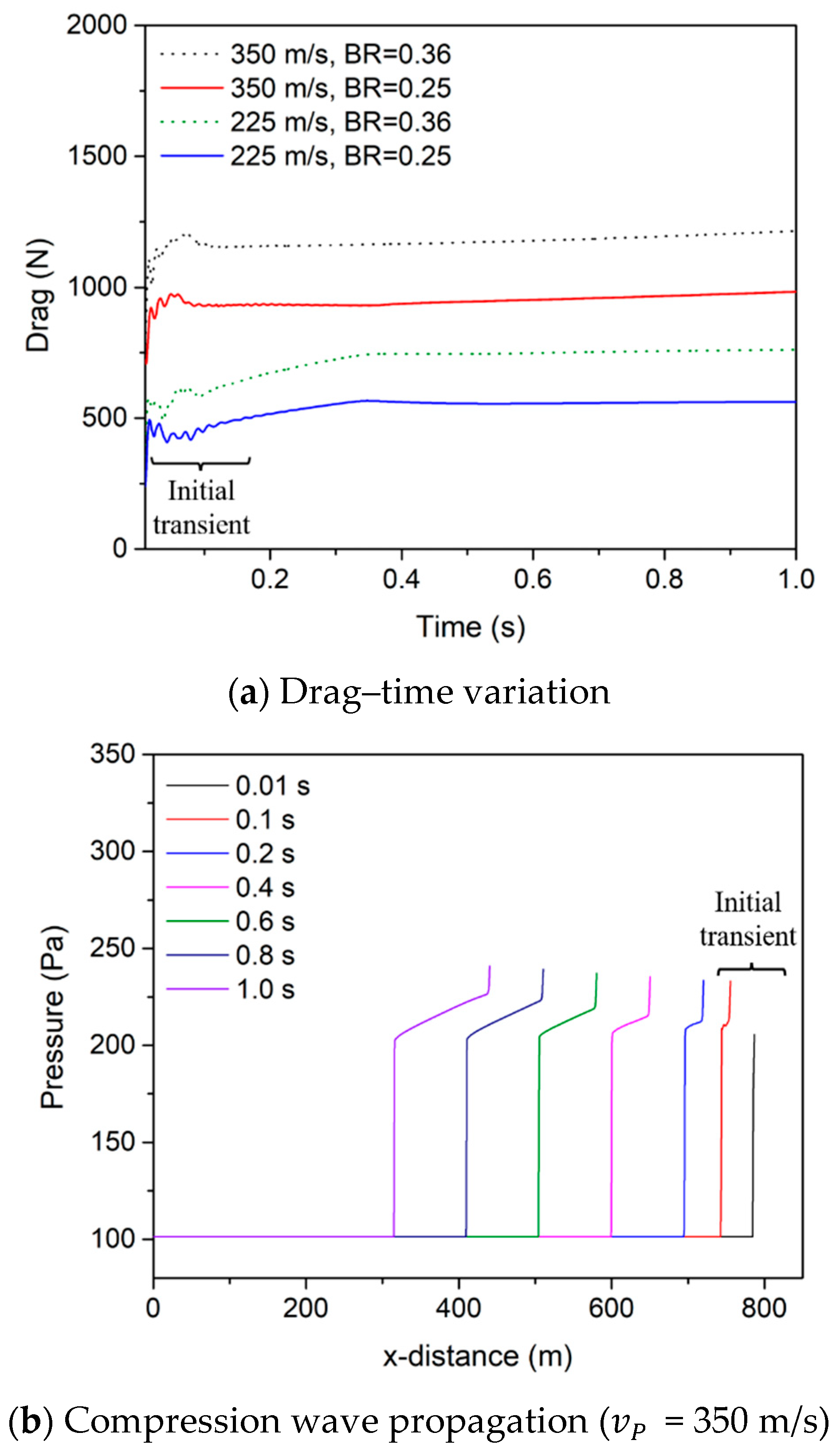
31]. However, in the Hyperloop system, the reference pressure is reduced to 1/1000 atm and the pressure waves have high amplitude, causing the nonlinear wave phenomenon. Therefore, the pressure wave propagation speeds are greater than the speed of sound.
Figure 12 compares the pressure wave propagation speeds induced at the front and rear end of the pod with the speed of sound. A higher BR creates higher pressure wave propagation speed at the front end of the pod
, but it barely affects the pressure wave propagation speed at the end of the pod
.
Figure 12a shows the values of pressure wave propagation speed (
) in absolute coordinates. The range of
is from 355 to 473 m/s, which is much higher than the normal speed of sound of 347.1 m/s. As
increases,
increases steeply. In the rear end of the pod,
did not change much and maintained a speed around the speed of sound. At
of 350 m/s, the differences between speed of sound and
for forward and backward flows are 26.6% and 0.6%, respectively. Note that in this study, the analysis of
is conducted under ideal operating conditions, where the tube walls are smooth and straight and without the application of a vacuum pump.
As shown in
Figure 12b, the pod-relative coordinates and the absolute coordinates are vastly different.
is much higher than
. This is because the directions of
and
are the same, in contrast to the direction of
, which is the opposite of
. That means as
increases, the difference between
and the compression wave speed decreases, whereas the difference between
and the expansion wave speed increases.
Figure 13 illustrates the pressure variation along the tube axis and the pod surface. As
increases, the pressure magnitude at the front of the pod significantly increases, whereas the pressure behind the pod slightly decreases. Compression waves are generated in front of the pod and propagate mainly in the forward direction faster than the speed of sound. These compression waves cause the pressure variation in front of the pod to fluctuate abruptly and generate a high-pressure region. Meanwhile, expansion waves are generated behind the pod, and propagate both in the forward and backward directions of the pod at around the speed of sound. The forward expansion waves pass the pod surface and merge with the incident compression waves, decreasing the pressure of the front waves. This phenomenon is probably observed at lower speeds, namely, 100 m/s and 150 m/s. This pressure wave distribution is similar to the variation in the high-speed train–tunnel system presented by Zonglin et al. [
13]. When
increases, the compressibility of air and the compression wave propagation speed increase, and consequently alter the forms of the high-pressure region in front of the pod.
Figure A4 (
Appendix C) describes this high-pressure region in more detail. By contrast, the position of the low-pressure region shows only a minor change. The oblique shockwaves caused by the reflection of waves between the tube walls and the pod tail are illustrated in
Figure 13 for
250 m/s.
Figure 14 shows the pressure variation along the tube axis in the front and rear of the pod (depicted in
Figure 15) for
s. Compression waves are generated ahead of the pod and propagate in the same direction, whereas expansion waves propagate in the opposite direction. The following equation presents the pressure ratio for flows across a normal shock [
27,
31]:
with
The term
in Equation (19) is the pressure term of the front shockwave shown in
Figure 16a.
Figure 16a compares the pressure magnitude of the front shockwave between BRs of 0.25 and 0.36. The results indicate that a higher BR produces a higher front shockwave pressure. In
Figure 12,
Figure 13 and
Figure 14, stronger compression waves form in front of the pod with increase of
. This behavior of front waves is similar to the phenomenon in the normal shockwave theory. Hence,
Figure 16b compares the compression wave propagation speed generated in front of the pod from the simulation with the ones calculated by Equations (19) and (20). There is a good agreement between the two results. Therefore, the compression wave generated in front of the pod in this study conforms to the normal shockwave theory.


