Article

Novel Design Framework for Dual-Band Frequency Selective Surfaces Using Multi-Variant Differential Evolution

by
Achilles D. Boursianis
1,*,†,
Maria S. Papadopoulou
1,†,
Spyridon Nikolaidis
1,†,
Panagiotis Sarigiannidis
2,†,
Konstantinos Psannis
3,*,†,
Apostolos Georgiadis
4,†,
Manos M. Tentzeris
5,† and
Sotirios K. Goudos
1,*,†
1
School of Physics, Aristotle University of Thessaloniki, 541 24 Thessaloniki, Greece
2
Department of Electrical and Computer Engineering, University of Western Macedonia, 501 50 Kozani, Greece
3
Department of Applied Informatics, School of Information Sciences, University of Macedonia, 546 36 Thessaloniki, Greece
4
School of Engineering and Physical Sciences, Heriot-Watt University, Edinburgh EH14 4AS, UK
5
The School of Electrical and Computer Engineering, Georgia Institute of Technology, Atlanta, GA 30332-0250, USA
*
Authors to whom correspondence should be addressed.
These authors contributed equally to this work.
Mathematics 2021, 9(19), 2381; https://doi.org/10.3390/math9192381
Submission received: 19 August 2021 / Revised: 18 September 2021 / Accepted: 21 September 2021 / Published: 25 September 2021
(This article belongs to the Special Issue Evolutionary Optimization Algorithms for Electromagnetic Devices)

Abstract

:
Frequency Selective Surfaces (FSSs) have become increasingly popular during the last years due to their combined characteristics, which meet, in general, the requirements of the next-generation wireless communication networks. In this work, a cross-platform design framework for FSS structures is presented and evaluated by utilizing a recently introduced evolutionary optimization algorithm, namely, the Multi-Variant Differential Evolution (MVDE). To the best of the authors knowledge, this is the first time that the MVDE algorithm is applied to a design problem in Electromagnetics. The proposed design framework is described in detail and the utilized evolutionary algorithm is assessed in terms of its performance by applying several benchmark functions. In this context, the MVDE is comparatively evaluated against other popular evolutionary algorithms. Moreover, it is applied to the design and optimization of two different representative examples of FSS structures based on three use cases of unit cell geometry. Optimization results indicate the efficacy of the proposed framework by quantifying the performance of the designed FSS structures in terms of several system metrics. The optimized FSS structures exhibit dual-band operation and quite acceptable results in the ISM frequency bands of 2.45 GHz and 5.8 GHz.

1. Introduction

Fifth-generation (5G) mobile communication systems have been started to deploy worldwide almost for two years. These systems, both from the operator and the end user perspective, require several frequency bands with Multiple-Input Multiple-Output (MIMO) architecture to operate properly [1,2,3]. Within this complex environment, various characteristics, such as spatial filtering [4], isolation [5], and decoupling [1], are of importance in the current and the next mobile communication networks, as several heterogeneous services with diverse features and multiple-frequency requirements are combined. Frequency Selective Surfaces (FSS) are electromagnetic (EM) devices that can integrate the above characteristics [6]. In the forthcoming years, Next-Generation Wireless Networks (NGWN) will face several challenges in their deployment, including ultra-low power consumption [7]. Towards a green environment, the Radio Frequency (RF) Energy Harvesting (EH) is a promising technique that can address this challenge effectively [8,9,10,11].
FSSs have been thoroughly studied in the literature during the last decades. Recently, researchers from academia and industry have shown their interest in FSSs, mostly because of their integrated characteristics and their large variety of applications. FSSs are electromagnetic structures that consist of a periodic structure [6]. The main functional characteristics of FSS include the transmission [12], absorption [13], or reflection [14] of electromagnetic radiation from the surrounding environment based on the frequency of the incident field. The key features that mostly affect the overall performance of an FSS structure are the selected geometry of the unit cell (square, circular, or even more sophisticated designs), the dielectric properties of the FSS structure substrate, and the inter-unit cell (fundamental element of an FSS structure) spacing [6].
The key to design an FSS structure, having the previously described functional characteristics, i.e., transmittivity, absorptivity, and reflectivity, is the geometry of the corresponding unit cell. Among all, unit cells of aperture-coupled patches [15], circular rings [16,17], fractals [18], annular rings [19], square loops [20,21], and Jerusalem-cross [22,23] have been introduced for the synthesis of the periodic structure in as FSS device. Beyond the use of widely known substrates for the design of an FSS structure in a PCB (Printed Circuit Board) [19,24,25,26,27,28,29,30,31], periodic structures have been also developed by utilizing ink [32,33,34], textile [35,36], metamaterial [37,38,39,40], liquid [41,42,43,44], and graphene [12,45,46,47,48] materials. FSS mainly operates as a spatial filter (band-pass filter [12,41,49,50] or band-reject filter [51,52,53]); however, it can exhibit various supported features in antenna design, such as beam steering [54,55,56,57], pattern reconfiguration [44,58,59], harmonic suppression in conjunction to metasurfaces [60] or miniaturized elements [61], and performance enhancement [62,63,64]. Recently, the feature of multi-functionality in FSS designs has been introduced by various research groups in the literature. Using p-i-n diodes and varactor diodes [65,66], liquid [44], or metamaterial surfaces [39], the proposed FSS structures achieved multi-functionality, by combining at least two of their main characteristics, i.e., transmittivity, absorptivity, or reflectivity.
The periodic structure of an FSS is also suitable to operate as a receiving module of a rectenna system (antenna + rectifier). Therefore, the FSS can be utilized in Radio Frequency (RF) Energy Harvesting (EH) applications by enabling the characteristic of absorptivity. In [67], the authors presented a novel application suitable for FSSs. The computed results of the proposed FSS design were validated by experimental measurements. The authors reported an RF-to-DC conversion efficiency of 25% and 15.9% for a 3 × 3 and 5 × 5 FSS design, accordingly, when the RF input power level was −6 dBm. Ashtari et al. [68] designed and fabricated a rectenna operating in the ISM frequency band of 2.45 GHz. The rectenna consisted of two square patch antennas, which were utilizing a FSS structure as a reflector of the proposed system. Experimental results showed a maximum RF-to-DC efficiency up to 79% for a 100 Ω load resistance when the RF input power was about 2.2 mW/cm2. The authors of [69] designed and experimentally validated a hybrid FSS structure and rectenna for RF EH applications. Each of the unit cells of the designed FSS structure acted as a probe-fed patch antenna. The proposed 3 × 4 hybrid FSS structure resulted in an RF-to-DC power conversion efficiency of 50%. A rectenna array assisted by an FSS structure was introduced in [70]. The proposed system operated in the frequency band of 5.8 GHz. Measured results exhibited an obtained power conversion efficiency of 76%. Erkmen et al. [71] introduced the feature of scalability to RF EH applications by utilizing FSS structures. The proposed system operated in the ISM frequency band of 2.45 GHz having a simple unit cell geometry of two patches. Experimental results of the fabricated prototype reported a power conversion efficiency of 61% when the RF input power was 15 dBm. Finally, the authors of [72] presented a dual-band FSS structure operating in the frequency bands of GSM-1800 and Wi-Fi 2.45 GHz for RF energy harvesting applications. The unit cell of the proposed FSS consisted of two bow-tie dipoles and a resistive load. Measured results of the fabricated FSSs exhibited RF-to-DC conversion efficiency of 43% and 31% for a 4-unit supercell, and RF-to-DC conversion efficiency of 27% and 29% for an 8-unit supercell, both at the frequency bands of GSM-1800 and Wi-Fi 2.45 GHz, accordingly.
Evolutionary optimization algorithms [73,74] are one of the three main categories of population-based meta-heuristic algorithms; the other two are physics-based [75] and swarm-intelligence algorithms [76,77,78]. Evolutionary algorithms (EAs) adopt mechanisms that are usually inspired by the biological evolution of natural environments, such as mutation, crossover, and selection. Each solution to the optimization problem acts as an individual candidate. The result of the cost function for each of the available solutions determines the activation of the previously mentioned mechanisms. In the course of iterations, the evolution of the population is taking place (based on these mechanisms) towards the convergence of the optimal solution. Various meta-heuristic optimization algorithms, such as the Genetic Algorithm (GA) [79,80], the Differential Evolution (DE) [81], the Self-Adaptive Differential Evolution [82], the Particle Swarm Optimization (PSO) [83], the Grey Wolf Optimizer (GWO) [84], and the Wind Driven Optimization (WDO) [85], have been considerably exploited by their application to the field of Electromagnetics [85,86,87,88,89,90].
Evolutionary optimization algorithms have been also applied to the design of FSS structures. In [91], an optimization process based on GAs [79,80] for the design of dual-band FSS structures was presented. The shape of the unit cell was optimized, and the polarization performance was assessed. A novel methodology for reconfigurable FSSs was introduced in [92] by utilizing the GAs. The optimization technique was applied to obtain the optimal choice of the switches to produce the desired frequency response. The authors of [93] discussed the synthesis of an FSS structure with a low cross-polarization level by utilizing the parallel binary-coded micro-genetic algorithm [94]. They optimized the pattern and the periodicity of the FSS along the x- and y-directions to minimize the cross-polarization level for a wide frequency band and a considerably large range of angles. The same algorithm was also applied to optimize FSS structures that operate as spatial filters [95] or as metamaterials in multi-frequency bands [96]. The combination of the genetic algorithm and the geometry-refinement technique [97] was introduced in [98] to design and optimize a multiband single-layer FSS. The derived result exhibited broader characteristics in terms of bandwidth operation.
Moreover, the DE [81] as well as the Covariance Matrix Adaptation Evolution Strategy (CMA-ES) [99] have been utilized in the design of FSS structures. In [100], the authors applied the optimization technique of differential evolution strategy to design an FSS structure. They also performed a comparison between the DE and the GA. From their results, they derived that the DE strategy exhibited comparative advantages against the GA. The same optimization technique (DE strategy) was also utilized in [101] to design a double-square loop as a unit cell in an FSS structure. Additionally, the authors of [102] applied the CMA-ES to efficaciously design and optimize the metallic shape of a unit cell in an FSS structure. Finally, FSS structures have been designed by the use of Swarm Intelligence (SI) algorithms. One of the most widely known algorithms, i.e., the PSO [83], has been applied to synthesize FSS structures [103,104,105]. Furthermore, the Multi-Objective Lazy Ant Colony Optimization (MOLACO), which is an extended version of Ant Colony Optimization (ACO) technique [106], was utilized in the design of a 3D FSS design [107]. Recently, the authors of [108] designed a dual-band single-layer FSS structure by utilizing the Harris Hawks Optimization (HHO) technique [109].
Various optimization tools and frameworks, mostly open-source, with applications in Electromagnetics, have been introduced in the literature over the past years. Among all, the authors of [110] presented two optimization packages for designing various technical devices and systems: the Agros environment and the A ¯ rton optimization toolbox. The former represents an environment of systems consisting of Partial Differential Equations (PDEs); it is a multi-physical Finite Element Method (FEM) solver that supports various 3D problems in Engineering, including Electromagnetics. The latter is basically an optimization toolbox for Python. It provides an efficient programming environment for a large variety of optimization methods. An open-source C++ library using FEM techniques with high-order meshing is described in [111]. MFEM (Modular Finite Element Methods) supports various algorithms, solvers, as well as hardware platforms that are utilized by the scientific community. Finally, OpenEMS [112] is a free and open-source electromagnetic solver based on the Finite Difference Time Domain (FDTD) method. It supports various features, such as 3D mesh, multi-threading, remote simulations capability, and MATLAB interface. If we consider the main features of various optimization tools and frameworks presented in the literature, we can conclude that their common advantage is the provision of open-source distribution. Most of them are based on a programming language (Python, C++, etc.) in order to operate properly. However, their main limitation is the lack of support in cross platforms.
In this work, a new cross-platform framework for designing and optimizing FSS structures as applied to various problems in Electromagnetics is analyzed and validated. The proposed design framework combines a recently introduced evolutionary optimization algorithm, namely, the Multi-Variant Differential Evolution (MVDE) algorithm [113], and a commercial high-frequency electromagnetic solver (HFSS; © 2020 ANSYS, Inc., Canonsburg, PA, USA). The novelty of our work lies in the fact that a complete optimization framework for designing FSS structures, and consecutively, various EM models, such as antennas, antenna arrays, microwave filters, etc., is provided. To the best of the authors’ knowledge, this is the first time that the MVDE algorithm is applied to solve an optimization problem in the field of Electromagnetics. Furthermore, a contributing characteristic of this work originates from the utilization of a pair of U-slots apertures in a corresponding set of patches as a unit cell in the optimization process of an FSS structure. Moreover, to the best of the authors’ knowledge, this is the first dual-band FSS absorber, which is suitable for RF energy harvesting applications, that is operating in the ISM Wi-Fi 2.45 GHz and Wi-Fi 5.8 GHz frequency bands. The design of an FSS structure, especially when the unit cell holds a geometry with a medium of high complexity, is a problem in Electromagnetics that can be classified as an optimization one. Taking into consideration the requirements of the next-generation communication networks in multi-frequency band operation, the design of dual- or multi-band FSS structures is a straightforward optimization process since the number of parameters (decision variables in an optimization problem) is considerably large.
The remainder of this work is structured as follows. Section 2 includes the applied methods and techniques for the presentation and the evaluation of the introduced design framework. Specifically, in Section 2.1, the problem of the optimization process is defined; in Section 2.2, the proposed design framework is analytically described; in Section 2.3, a brief description of the utilized MVDE algorithm is included; and in Section 2.4, the applied algorithm is assessed in terms of its performance against 4 widely-known evolutionary algorithms. Section 3 presents and discusses the optimization results obtained by the utilization of the proposed framework to design and optimize two representative examples of FSSs structures that exhibit dual-band frequency operation. In detail, Section 3.1 describes the parameters that are considered to set up the optimization process for designing both the unit cell and the FSS structure, whereas Section 3.2 and Section 3.3 include the main results based on several system metrics obtained by the optimization process. Finally, Section 4 concludes the findings and outlines the future steps of this work.

2. Materials and Methods

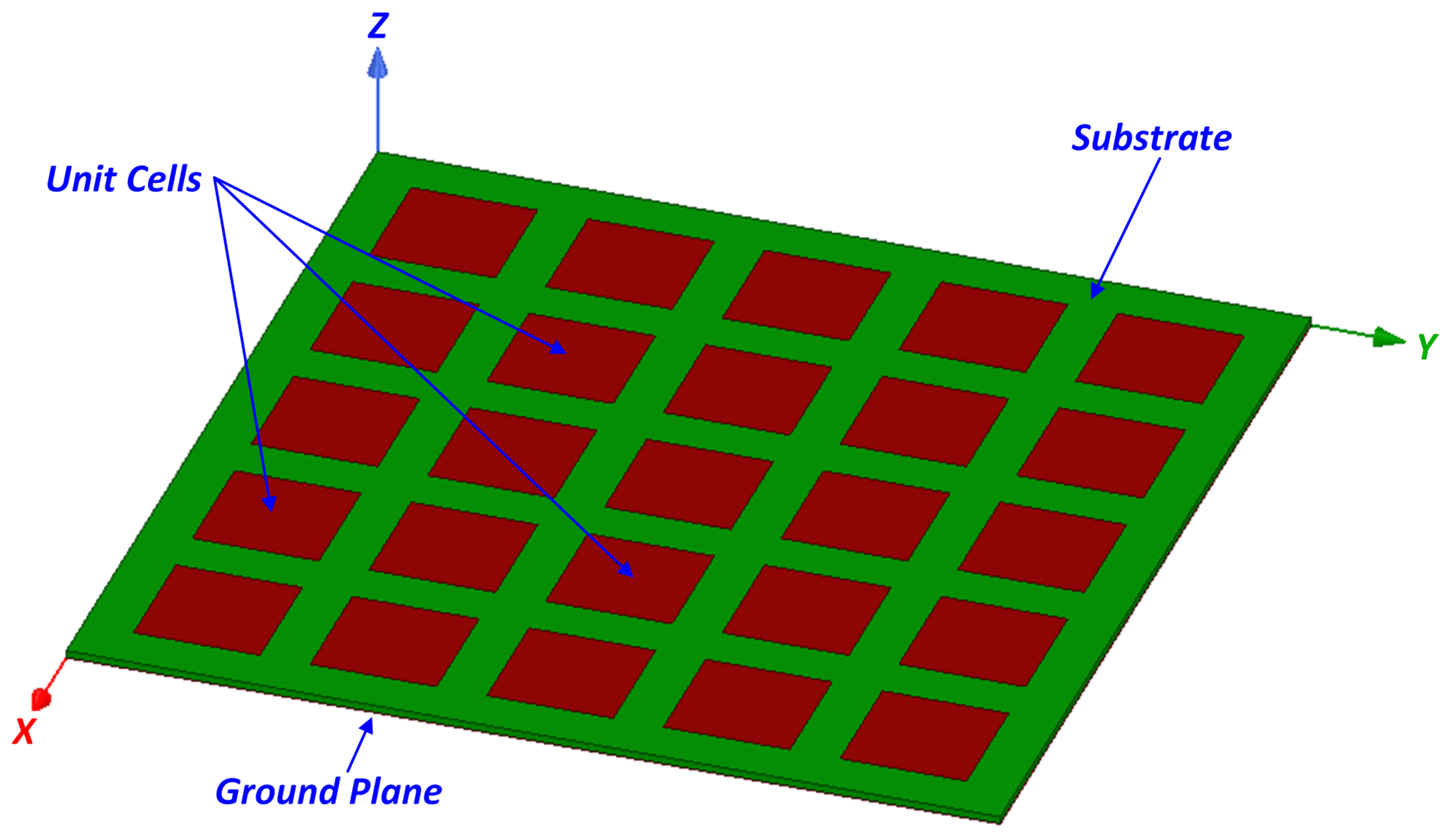
2.1. Problem Definition

Figure 1 pictures the generalized approach of a single-layer FSS structure. Without losing the generalization of the problem definition, a single-layer FSS design (a similar problem definition can be expressed for dual- or even triple-layer FSS structures) consists of a unit cell (usually of metal) which is periodically repeated along a two-dimensional lattice. Beneath the lattice of the unit cells, a grounded substrate layer (usually of dielectric) is placed. Based on the electromagnetic theory, when an incident field triggers the FSS structure, the latter one performs as an absorber [13], a reflector [14], or a transmitter [12], based on the frequency of the incident field. The shape and the size of the unit cell is usually the main challenging and demanding task in the optimization process [114] as they determine the resonance of the FSS structure in the desired frequency band and, consecutively, its performance as an aftereffect of its functional characteristics.

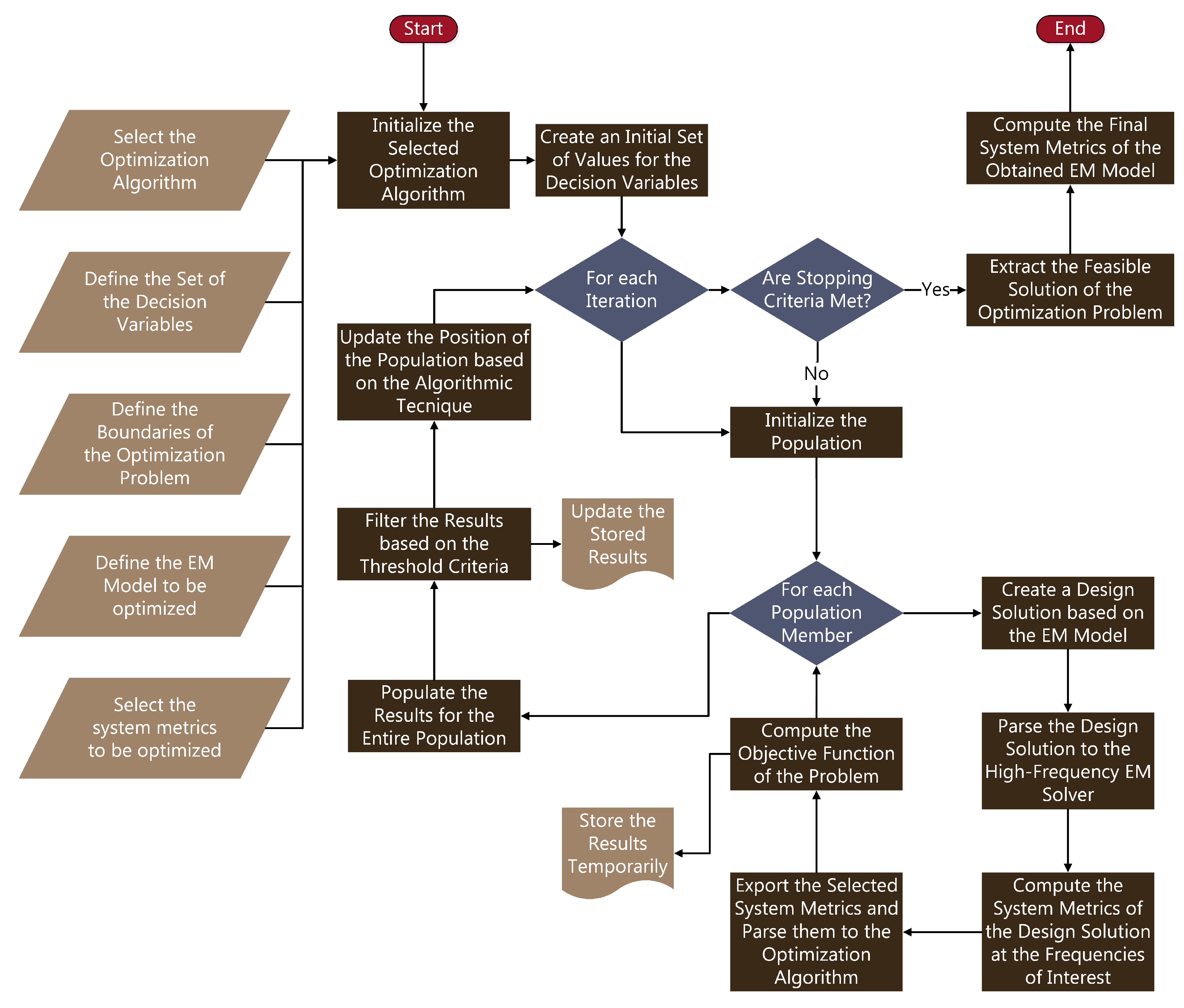
2.2. Optimization Process

In this work, a new cross-platform design framework for FSSs based on evolutionary optimization algorithms is presented. The proposed framework combines the advantages of a commercial high-frequency electromagnetic solver (HFSS; © 2020 ANSYS, Inc., Canonsburg, PA, USA) and the robustness of an evolutionary optimization algorithm, i.e., the MVDE [113], which was recently introduced in the literature and is briefly described in Section 2.3. The proposed framework is a generalized approach for obtaining feasible solutions to the design of antenna structures based on optimization algorithms. Figure 2 displays the general concept and the main steps of the proposed design framework that can be applied in several antenna optimization problems and can be combined with various evolutionary optimization algorithms. We should point out that the proposed framework can be utilized with several different meta-heuristic algorithms, and with other optimization problems as well if certain modifications are applied.
Analyzing the proposed design framework that is displayed in Figure 2, the first step includes the initialization of the selected optimization technique, i.e., the MVDE algorithm in our case. Prior to the initialization of the algorithm (i.e., the definition of (a) the population number, (b) the number of the independent trials, (c) the dimensionality of the optimization problem, and (d) the control parameters), the decision variables that fully described the EM structure geometry must be defined, as well as their boundaries to the given optimization problem. Moreover, the definition of the EM model (i.e., in our case the FSS structure models, both unit-cell and total structure), as well as the systems metrics to be optimized, are also required. Based on the optimization problem and the model of the EM structure, various system metrics can be utilized, such as the magnitude of the reflection coefficient ( S 11 ), the realized gain, the characteristic impedance, or the efficiency of the proposed EM structure [86,88,90,114]. In this work, we have selected the magnitude of the reflection coefficient as the system metric to be optimized. However, for each of the given solutions, the characteristic impedance of the FSS structure, as well as the realized gain at the desired frequencies are also computed and evaluated.
The second step in the optimization process creates a set of values for the decision variables of the optimization problem [89], and, at each iteration, the population of the selected algorithm is initialized. Additionally, at each population member, a design solution based on the EM model (e.g., FSS structure) is created and parsed to the high-frequency EM solver, which computes the selected system metrics at the frequencies of interest. The results are reported back to the optimization algorithm to compute the objective function of the problem [86]. These results are stored temporarily, until the threshold criteria are applied. Once the computation of the objective function is completed for every member of the entire population, the results are populated to the optimization algorithm. Based on the selected algorithm (i.e., MVDE), the best values of the position and the objective function for the members of the population are stored [86], and the specific mechanisms for parent selection and crossover mutation are taking place. The current iteration is completed by updating the position of the population, and by storing the results for the next iteration.
The optimization process is concluded when the stopping criteria are met, i.e., when the number of maximum iterations or maximum function evaluations is achieved or the system metrics values are satisfied [86,88,89]. As a result, the feasible solution of the optimization problem is extracted and the final design of the EM structure is obtained. Based on the final design, a set of system metrics (optimized and/or not) is computed to obtain the final results of the proposed EM structure geometry.

2.3. MVDE Algorithm Description

MVDE algorithm has been recently introduced in the literature [113]. It is a stochastic and population-based evolutionary algorithm that combines five different variants of the legacy DE algorithm [81] to balance the exploration and the exploitation phases of searching the computational space during the iterative process. The utilized DE variants in MVDE are DE/rand/1, DE/current-to-best/1, DE/rand/2, DE/best/2, and DE/best/1 [115]. The multi-variant mutation schemes are incorporated with a self-adaptive scaling factor based on the probabilistic cosine and logistic distributions. The introduction of the adaptive scaling factor in the MVDE algorithm is applied to enhance the performance of the legacy DE algorithm, i.e., to mitigate the probability of trapping in local minima and to avoid premature convergence. The pseudocode of the MVDE algorithm is outlined in Algorithm 1.
To briefly describe the optimization technique of the MVDE algorithm, let us consider the definition of N P o p as the population number ( k = 1 N P o p ), D as the number of decision variables ( j = 1 D ), M a x V a r and M i n V a r as the upper and the lower boundary of the decision variables, and  M A x I t as the maximum number of iterations ( i = 1 M a x I t ). At the first iteration ( i = 1 ), the initial values of the position u k and the corresponding objective function O F k for each member of the population are selected. A ranking process determines the best values of the position and the corresponding objective function for each member of the population. For all the following iterations ( i > 1 ), the crossover factor ( C F ) is computed by
C F = i 2 × M a x I t
At the current iteration i, and for each member of the population, the self-adaptive scaling factor [ S F ] k , D is computed based on the cosine or the logistic distribution. It is expressed by
[ S F ] k , D = 2 π s i n 1 2 × [ r a n d ] k , D 1 , cos ine distributio [ r a n d ] k , D 0.1 × l o g 1 [ r a n d ] k , D 1 , logistic distribution
where [ r a n d ] k , D is a uniformly distributed random number. The derived self-adaptive scaling factor is further computed by applying a binary matrix, which is given by
[ B ] k , D = [ r a n d ] k , D > C F
Therefore, the expression of the self-adaptive scaling factor is defined as
[ S F ] k , D = [ B ] k , D × [ S F ] k , D
Moreover, the parents’ selection is based on the expression
N P o p p = k × ( 1 C R )
The next step in the optimization technique of the MVDE algorithm is the computation of the position for each member of the population at the next iteration, based on one of the five different variants of the legacy DE algorithm. The position is expressed by
[ u ] k , D i + 1 = [ u ] r 1 , D i + [ S F ] k , D i + 1 × [ u ] r 2 , D i [ u ] r 3 , D i + [ S F ] k , D i + 1 × [ u ] r 4 , D i [ u ] r 5 , D i , DE / rand / 1 [ u ] r 1 , D i + [ S F ] k , D i + 1 × [ u ] r 2 , D i [ u ] r 3 , D i , DE / current to best / 1 [ u ] k , D i + [ S F ] k , D i + 1 × [ u ] b e s t , D i [ u ] k , D i + [ S F ] k , D i + 1 × [ u ] r 1 , D i [ u ] r 2 , D i , DE / rand / 2 [ u ] b e s t , D i + [ S F ] k , D i + 1 × [ u ] r 1 , D i [ u ] r 2 , D i + [ S F ] k , D i + 1 × [ u ] r 3 , D i [ u ] r 4 , D i , DE / best / 2 [ u ] b e s t , D i + [ S F ] k , D i + 1 × [ u ] r 1 , D i [ u ] r 2 , D i , DE / best / 1
Finally, based on the position [ u ] k , D i + 1 , the objective function O F k i + 1 of the optimization problem is computed for each member of the population. The best values of the position u k b e s t and the corresponding objective function O F k b e s t are updated and the process is iterated until the stopping criteria are met. Ultimately, the feasible solution of the EM structure is extracted and the final system metrics are computed.

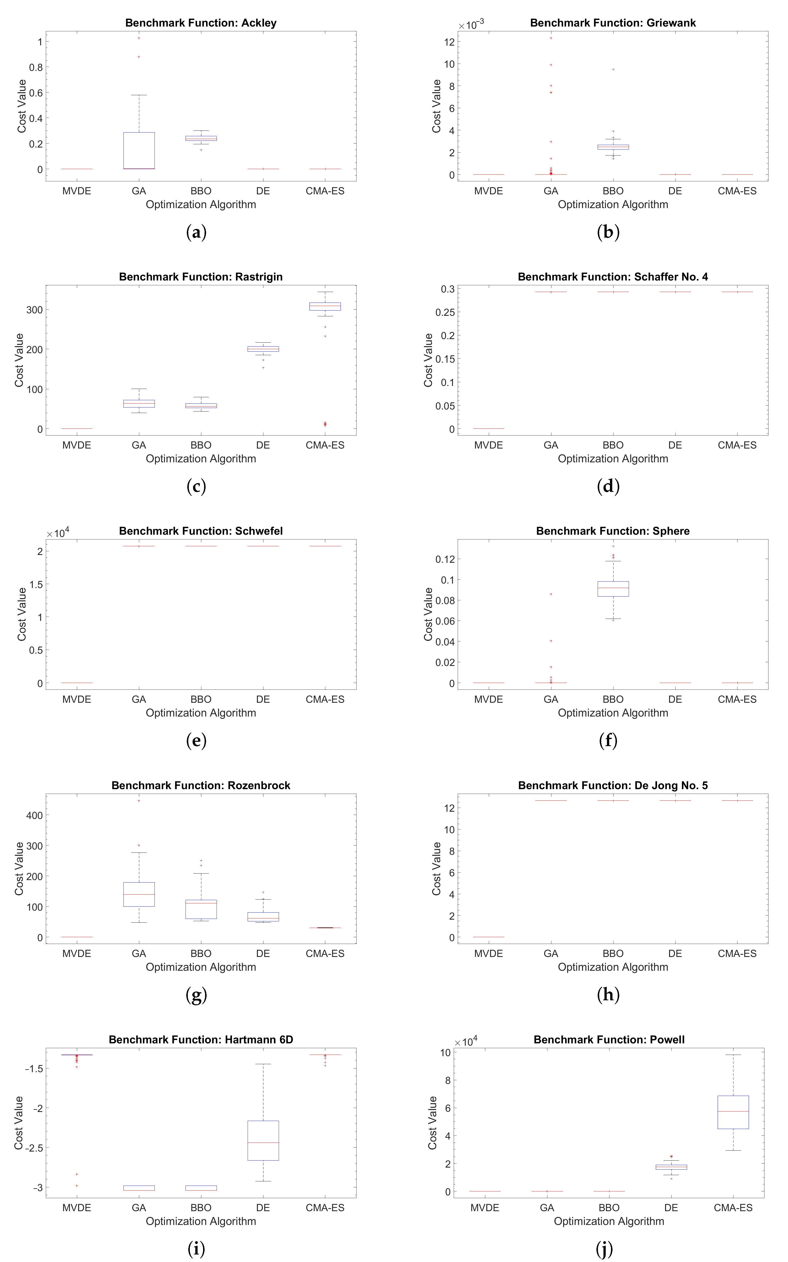
2.4. Performance Evaluation

The MVDE algorithm in the proposed design framework has been evaluated in terms of its performance by utilizing four widely known evolutionary algorithms, i.e., the GA [79,80], the Biogeography-Based Optimization (BBO) [116], the DE [81], and the CMA-ES [99]. The performance score for each of the aforementioned algorithms is assessed by utilizing ten commonly used benchmark functions: Ackley ( f 1 ), Griewank ( f 2 ), Rastrigin ( f 3 ), Schaffer No. 4 ( f 4 ), Schwefel ( f 5 ), Sphere ( f 6 ), Rozenbrock ( f 7 ), De Jong No. 5 ( f 8 ), Hartmann 6D ( f 9 ), and Powell ( f 10 ). The definition of the utilized benchmark functions is quoted in Appendix A. For a fair comparison between the utilized MVDE algorithm in the proposed design framework and the selected evolutionary algorithms, the following parameters are applied:
  • Independent trials: 100;
  • Iterations: 1000;
  • Population: 100;
  • Decision variables (solutions to the optimization problem): 30 and 50;
  • Decision variables boundaries: [−10 10].
Table 1 lists the obtained results of the performance evaluation for the MVDE algorithm in conjunction with four popular evolutionary algorithms by computing the average values of the cost function of 100 independent trials, having the number of the decision variables equal to 30 and 50. From the obtained results, we can infer that the utilized MVDE algorithm that is integrated into the proposed design framework outperforms in both cases of the solutions to the optimization problem (i.e., D = 30 and D = 50) and for the whole set of the selected benchmark functions. The MVDE algorithm exhibits its effectiveness to balance between the exploration and the exploitation in the search space, and its robustness to efficiently converge to the global minima in a variety of benchmark functions.
Algorithm 1 Pseudocode of the Multi-Variant Differential Evolution Algorithm
1:
Define the maximum number of iterations M a x I t ( i = 1 M a x I t ), the number of decision variables D ( j = 1 D ), the upper M a x V a r and lower M i n V a r boundary of the decision variables, and the population number N P o p ( k = 1 N P o p )
2:
Select the initial values of the position vector u k and the corresponding objective function O F k for each member of the population
3:
Compute the best values of the position ( u k b e s t ) and the objective function ( O F k b e s t ) for i = 1
4:
for ( i = 2 ; i + + ; i M a x I t ) do
5:
     Compute the crossover factor C F using (1)
6:
     for ( k = 1 ; k + + ; k N P o p ) do
7:
          if ( r n d > 3 × C F ) then
8:
               Compute the self-adaptive scaling factor [ S F ] k , D by applying the cosine distribution of (2)
9:
          else
10:
               Compute the self-adaptive scaling factor [ S F ] k , D by applying the logistic distribution of (2)
11:
          end if
12:
          Compute the binary matrix using (3)
13:
          Compute the self-adaptive scaling factor [ S F ] k , D using (4)
14:
          Compute the parent selection in each iteration using (5)
15:
          if ( i < 0.2 × M a x I t ) then
16:
               Compute the position [ u ] k , D i + 1 using the DE/rand/1 variant of (6)
17:
          else if ( i < 0.4 × M a x I t ) then
18:
               Compute the position [ u ] k , D i + 1 using the DE/current-to-best/1 variant of (6)
19:
          else if ( i < 0.6 × M a x I t ) then
20:
               Compute the position [ u ] k , D i + 1 using the DE/rand/2 variant of (6)
21:
          else if ( i < 0.8 × M a x I t ) then
22:
               Compute the position [ u ] k , D i + 1 using the DE/best/2 variant of (6)
23:
          else
24:
               Compute the position [ u ] k , D i + 1 using the DE/best/1 variant of (6)
25:
          end if
26:
          Compute O F k i + 1 = F ( [ u ] k , D i + 1 )
27:
          Update the best values of u k b e s t , O F k b e s t
28:
     end for
29:
end for
To quantify the derived conclusion based on the presented results, the Friedman nonparametric statistical test is applied as a meta-performance metric to assess the efficacy for each of the selected algorithms based on the mean ranking. Table 2 summarizes the obtained results. We can easily conclude that the MVDE algorithm achieves the best score of the mean ranking, having the second-best score by CMA-ES. We should also point out that the legacy DE algorithm achieves the last score of the mean ranking in the Friedman test, mostly due to the drawbacks of trapping in local minima and of early convergence.
Figure 3 and Figure 4 illustrate the boxplot distributions of the computed results, i.e., the cost function values for the 100 independent trials of the selected benchmark functions, for the MVDE algorithm against four popular evolutionary optimization algorithms, and for D = 30 and D = 50, accordingly. The boxplot distribution is a figure of merit to assess the performance for each of the selected algorithms to the given benchmark functions. From the presented results, we can conclude that the MVDE algorithm, which is utilized in the proposed design framework, exhibits considerable stability and robustness in a variety of benchmark functions, i.e., functions with many local minima, bowl-shaped, valley-shaped, steep ridges, or other characteristics. We should also point out that the 25th percentile and the 75th percentile of the given distributions for the MVDE algorithm achieve an indistinguishable variation (for any of the selected benchmark functions).

3. Optimization Results and Discussion

The proposed design framework, by incorporating a recently introduced evolutionary algorithm, namely, the MVDE algorithm [113], and a commercial high-frequency electromagnetic solver (HFSS; © 2020 ANSYS, Inc., Canonsburg, PA, USA), has been applied in an iterative process to design, optimize, and obtain a feasible solution of an FSS structure suitable for RF EH applications. To this end, the absorptive characteristic of the FSS structure is exploited and the corresponding system metrics are utilized in the optimization process. Section 3.1, Section 3.2 and Section 3.3 present the optimization setup that has been applied in the process, the general concept, as well as the main steps in designing and optimizing an FSS structure with a complex unit cell.

3.1. Optimization Setup

The optimization setup of designing a unit cell, and consecutively an FSS structure based on the selected unit cell, includes the definition of the unit cell geometry, i.e., the type of the absorber and the decision variables that fully describe its geometry [114]. Figure 5 portrays the proposed geometry of a unit cell as an EM structure. The proposed unit cell that forms an absorber (Figure 5a) consists of a pair of symmetrical patches (two axes of symmetry occur), which harvest the EM radiation of the surrounding environment in the desired frequency bands. Each of the two patches in the proposed unit cell includes a U-slot within a predefined by the patch surface, to achieve the second resonance of the total EM structure (the first resonance occurs from the patch dimensions). The harvested energy is directed to the terminal port (which is the reference point where the energy is converted) of the EM structure through the microstrip lines, one for each of the corresponding patches. The described geometry of the proposed unit cell can be repeated in both of the axes that define the plane of the unit cell (in our case this is the XY plane as Figure 5a indicates).
Based on the absorber of Figure 5a, three use cases of the proposed unit cell are determined and included in the optimization process. These are portrayed in Figure 5b–d. The first use case of the proposed unit cell exhibits two axes of symmetry (axes X and Y of the Figure 5b), where the U-slot is centered along the X-axis. In the second use case, the Y-axis of symmetry is omitted, thus allowing to offset the U-slot within the patch of the absorber, by introducing the O x s decision variable (Figure 5c). The third use case of the proposed unit cell differentiates the starting point of the O x s decision variable that affects the offset of the U-slot (Figure 5d).
If we take into consideration the Figure 5b, we can conclude that the number of decision variables that are required to fully describe the geometry of the proposed unit cell is equal to 10. We should also clarify that D is equal to 10 only for the first use case of the proposed unit cell, the second and the third use cases require an extra decision variable for their geometry description; therefore, in these cases, D is equal to 11. Such a geometry is practically impossible to describe analytically using the electromagnetic theory; the use of an optimization method to obtain a feasible solution of a unit cell and consecutively, of a dual-band FSS design as an EM structure, is a straightforward process. In this work, we analyze the operation of the proposed design framework by combining an evolutionary optimization algorithm (MVDE) [113] and a commercial electromagnetic solver (HFSS).
To design and optimize the performance of various use cases of a unit cell and the corresponding FSS structure, we exploit the characteristic of absorptivity [13]. This characteristic results in EM structures with maximum values of the magnitude of absorptivity in the frequency bands of interest or, equivalently, with minimum values of the magnitude of the reflection coefficient [114]. As a result, the objective of the given optimization problem can be reworded as the minimization of the magnitude of the reflection coefficient at the frequency bands of interest for each of the designed EM structures (unit cell, FSS structure). By minimizing the reflection coefficient at the terminal port of the EM structure, the impedance matching between the designed EM structure and the reference point (in practical RF EH systems, the reference point is referred to the module that transforms the RF energy to DC voltage, i.e., the RF-to-DC rectifier in a rectenna system) occurs, and consecutively, the impedance of the designed EM structure tends to reach the characteristic value of 50 Ω . In this work, we express the given optimization problem by minimizing the reflection coefficient as the system metric of the designed EM structures (objective function of the optimization problem); however, the system metrics of the impedance, the radiation pattern, and the realized gain are also considered [117,118] to extract the feasible solution of the optimization problem.
During the initialization phase of the optimization process in the proposed design framework, the following parameters are applied to the MVDE algorithm:
  • Independent trials: 10;
  • Iterations: 200;
  • Population: 50;
  • Decision variables (solutions to the optimization problem): 10 (UC1), 11 (UC2, UC3).
The number of function evaluations, which acts as a stopping criterion in the optimization process, is equal to 10,000, and the threshold criterion for an acceptable solution of the optimization problem is set to −10 dB. As a result, the objective function of the previously described optimization problem can be formulated as
Minimize O F ( u ) = m a x S 11 2.45 GHz ( u ) , S 11 5.8 GHz ( u ) + Ψ × m a x 0 , S 11 2.45 GHz ( u ) T dB + Ψ × m a x 0 , S 11 5.8 GHz ( u ) T dB
where
  • u is the position vector for each member of the population of the utilized MVDE algorithm,
  • S 11 i (i = {2.45 GHz, 5.8 GHz}) is the system metric (magnitude of the reflection coefficient) of the designed EM structure at the specific frequencies of interest,
  • T d B is the threshold criterion for an acceptable solution of the optimization problem provided by the members of the population (in our case T d B =−10 dB),
  • Ψ is a positive number (multiplying factor in the objective function) that is triggered when the obtained solution is above the threshold criterion, and
  • O F is the objective function of the optimization problem.

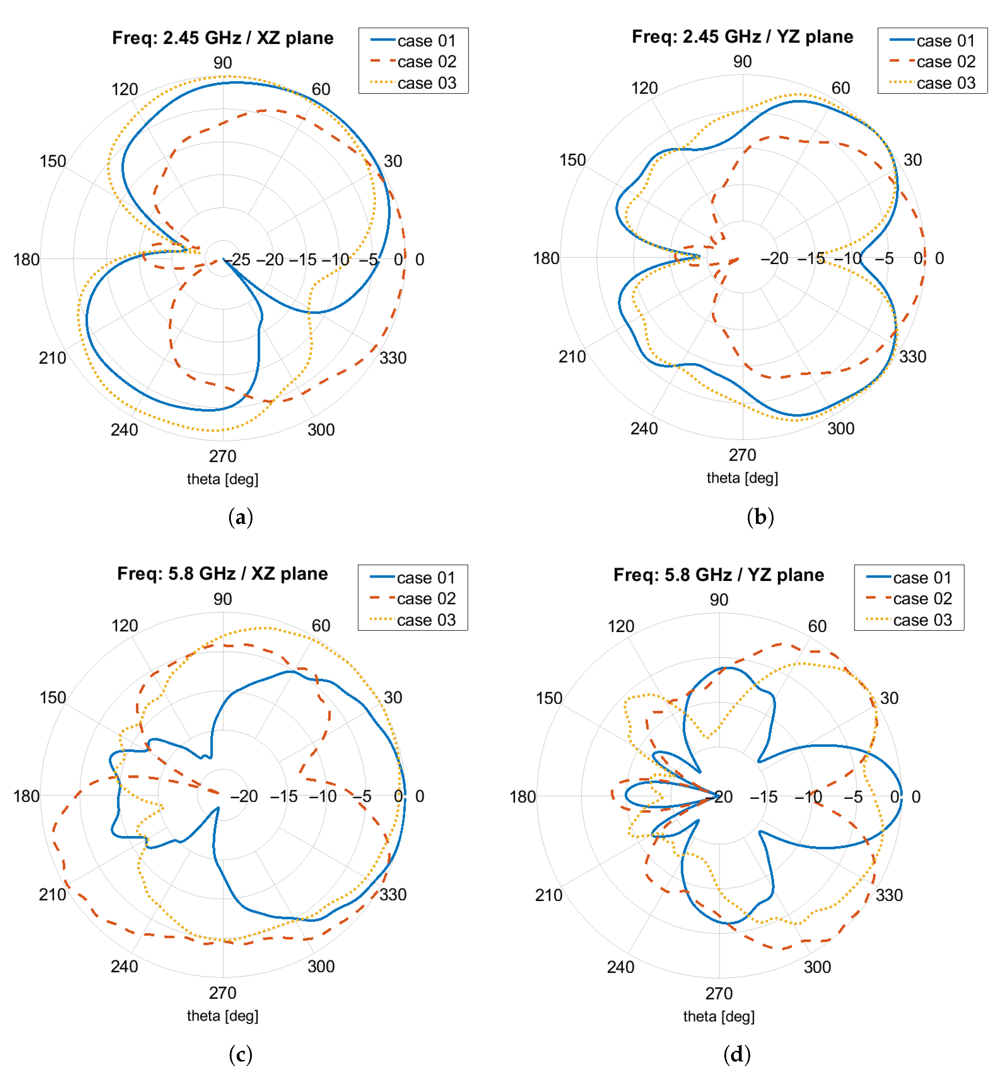
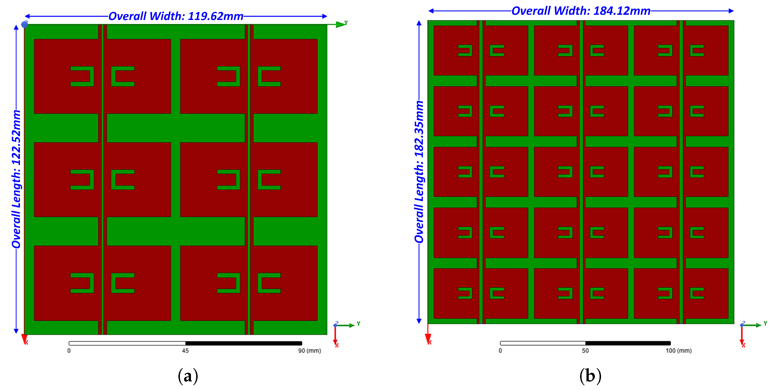
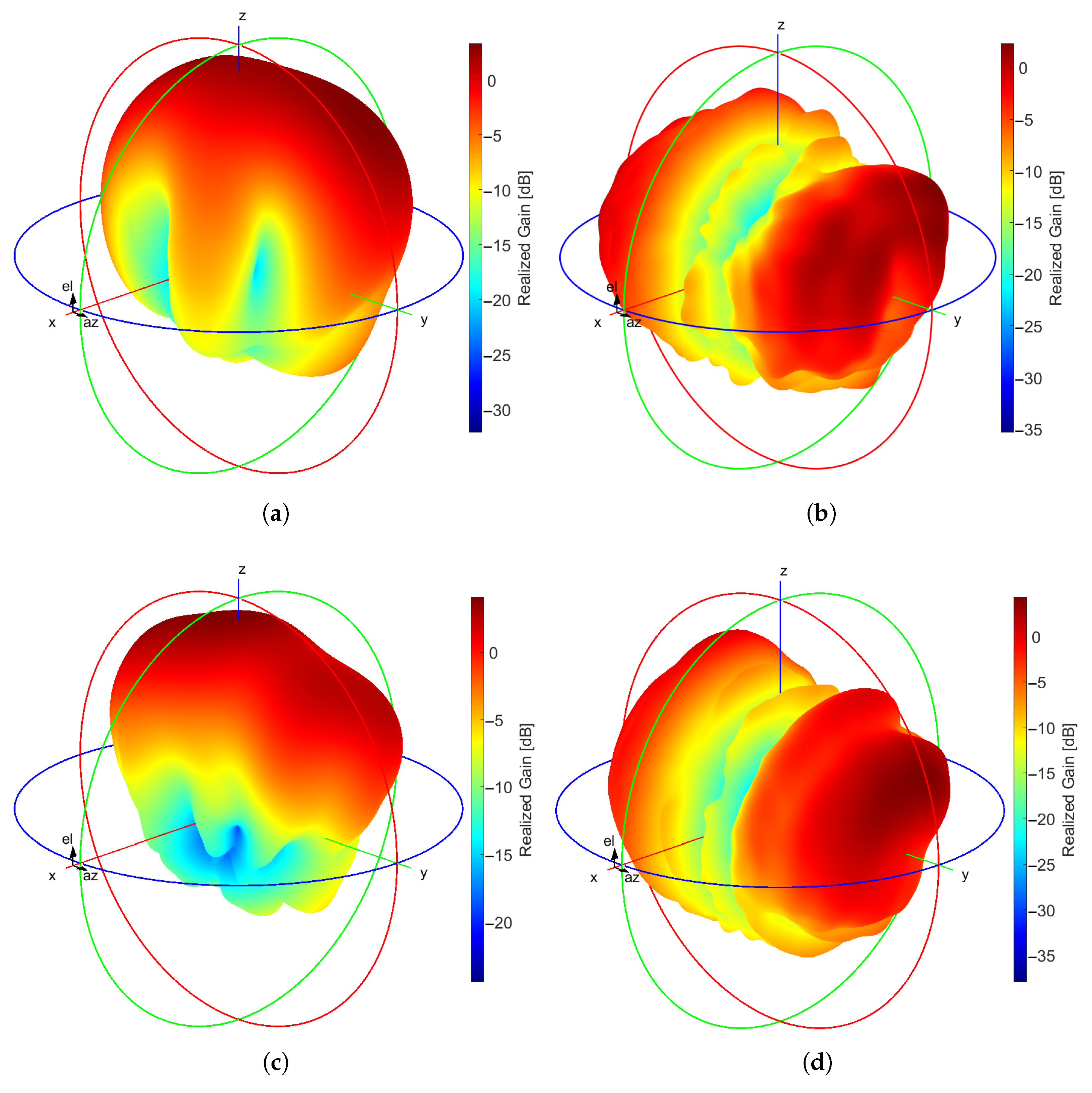
3.2. Unit Cell Results
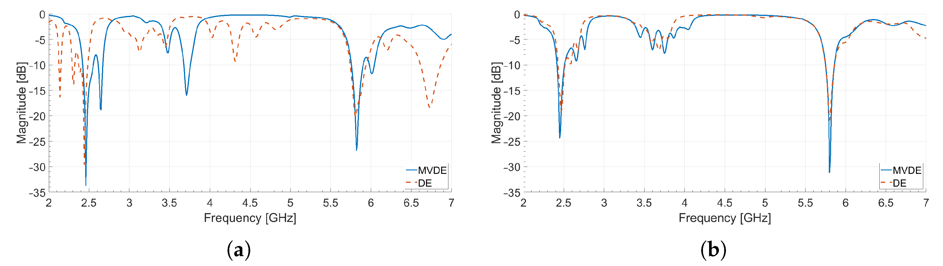
Figure 6 illustrates the final design solution of the unit cell for each of the use cases that are obtained by the proposed design framework and the applied optimization process. Moreover, Table 3 lists the final values of the decision variables that fully describe the geometry for each of the presented unit cell use case of Figure 6.
In order to design an FSS structure suitable for RF EH applications, the performance results of the unit cell use cases should be assessed. Figure 7 displays the comparative results of the S 11 magnitude of the reflection coefficient (final values of the system metric extracted from the obtained EM model using the proposed design framework and the optimization process of Figure 2) for each of the unit cell use cases. From the presented results, we can conclude that the first use case of the unit cell design achieves the best performance in terms of its reflection coefficient. In detail, the magnitude of the reflection coefficient is −48.78 dB at 2.45 GHz and −46.71 dB at 5.8 GHz for the first use case, −34.90 dB at 2.45 GHz and −25.24 dB at 5.78 GHz for the second use case, and −39.52 at 2.45 GHz, and −32.88 dB at 5.8 GHz for the third use case.
Figure 8 presents the comparative results of the achieved impedance for each of the unit cell use cases, whereas Table 4 lists the extracted results of the impedance at the frequencies of interest. From the presented results, we can infer that the first use case of the designed and optimized unit cell use cases exhibits the best results against the other two solutions in terms of its matching performance to the characteristic impedance of 50 Ω .
Figure 9 depicts the comparative results of the radiation pattern at the XZ and YZ planes of interest for each of the unit cell use cases. From the depicted results, we can deduce that the first and the third use cases of the unit cell exhibit the best performance in terms of its beamwidth operation. For example, both the first and the third use cases achieve a half-power bandwidth (HPBW) larger than 105 deg for the XZ plane and at the frequency band of 2.45 GHz (the corresponding HPBW of the second use case is smaller than 100 deg). Consecutively, the HPBW for the first and the third use cases is larger than 90 deg for the XZ plane and the frequency band of 5.8 GHz, whereas the second use case achieves an HPBW of less than 55 deg for the same main plane and frequency band, respectively.
In conclusion, the first of the presented unit cell use cases in the design of an FSS structure by utilizing the proposed design framework exhibits comparative benefits in terms of the main system metrics that are taking into consideration in an EM structure suitable for RF EH applications. Therefore, the geometry of the first use case will be utilized as a unit cell in two different FSS structures presented in Section 3.3.

3.3. FSS Results

Figure 10 illustrates two representative designed and optimized solutions of an FSS structure based on the design, optimization, and the comparative results of the first of the unit cell use cases presented in Section 3.2. The first one (Figure 10a) is an FSS structure of 3 × 2 unit cells, whereas the second solution (Figure 10b) consists of 5 × 3 unit cells. Such a design, operating in the ISM frequency bands of 2.45 GHz and 5.8 GHz, and having a relatively small size, makes it a strong candidate for a receiving module in practical indoor RF EH applications.
In Section 2.4, the MVDE algorithm that is included in the proposed design framework is assessed in terms of its performance. To this end, four evolutionary optimization algorithms, namely, the GA [79,80], the BBO [116], the DE [81], and the CMA-ES [99], and 10 popular benchmark functions, are utilized to compare their performance. To further validate our proposed framework when designing an FSS structure, a separate optimization process is carried out by utilizing the legacy DE algorithm [81] (besides the optimization process where the proposed MVDE algorithm [113] is applied), in order to compare and evaluate their performances using the selected system metrics of the EM structure. We should also point out that, in the optimization process of the proposed design framework, the utilized algorithms (MVDE, DE) are applied using the same parameters, as described in Section 3.1. The result of the comparison between the MVDE and the legacy DE algorithm in the optimization process of the proposed framework is depicted in Figure 11.
From the displayed curves of Figure 11, we can conclude that the optimized 3 × 2 and 5 × 3 FSS structures resonate at the desired frequency bands of Wi-Fi 2.45 GHz and 5.8 GHz. Moreover, we can infer that the result for the magnitude of the reflection coefficient of the MVDE algorithm outperforms the result of the legacy DE algorithm both for the two representative solutions of FSS structures, i.e., 3 × 2 FSS design and 5 × 3 FSS design, at the frequency bands of interest. Table 5 summarizes the performance comparison between the two evolutionary algorithms by listing the minimum values of the reflection coefficient in the desired frequency bands. From the depicted results, we can conclude that the incorporation of the recently introduced MVDE algorithm to the optimization process of the proposed design framework obtains an improvement in the magnitude of the reflection coefficient at the frequency bands of interest. In detail, if we consider the 3 × 2 FSS design, there is an improvement of 4.14 dB and 6.59 dB for the ISM Wi-Fi frequency bands of 2.45 GHz and 5.8 GHz, accordingly. Additionally, for the 5 × 3 FSS design, the improvement raises to 5.24 dB and 10.27 dB, for the same frequency bands of interest, accordingly.
Figure 12 displays the magnitude of the S i j parameters ( i j , 3 × 2 FSS design: ( i , j = 1 , 2 ), 5 × 2 FSS design: ( i , j = 1 , 2 , 3 )) that is obtained by utilizing the aforementioned optimization process and the proposed design framework. From the displayed results, we can conclude that the mutual coupling (usually the system metric that express the isolation between two or more terminal ports is the S i j parameter) is below −20 dB between the two and the three terminal ports, for the use case of 3 × 2 FSS design and 5 × 3 FSS design, respectively. Therefore, the isolation in both cased between the reference points is kept at acceptable values for the whole frequency bands of interest.
Figure 13 portrays the final results of the realized gain for the two representative examples of FSS structures by applying the proposed design framework along with the use of the MVDE algorithm. From the presented results, we can infer that the optimized FSS structures exhibit acceptable values of the gain performance in the desired frequency bands. In detail, for the 3 × 2 FSS design, the maximum achieved gain is 3.07 dBi and 2.32 dBi, for the Wi-Fi frequency bands of 2.45 GHz and 5.8 GHz, accordingly. Furthermore, a maximum HPBW of 128 deg at the YZ plane is obtained. Additionally, for the 5 × 3 FSS design, the maximum attained gain is 4.09 dBi and 4.30 dBi, for the Wi-Fi frequency bands of 2.45 GHz and 5.8 GHz, respectively. Moreover, a maximum value of 111 deg is achieved for the system metric of HPBW at the YZ plane.
Finally, Table 6 summarizes the comparative results of this work against selected published works from the literature. The selection was made based on the functional characteristics of the published FSS structures and the provided data. The parameters for the comparison are the PCB substrate, the type of the unit cell, the frequency band of operation, the derived layout of the FSS structure, the total occupied area of the FSS structure expressed in wavelengths with respect to the lowest resonant frequency of the FSS, the magnitude of the reflection coefficient, and the reference frequency of the S 11 parameter. From the listed results of Table 6, we can infer that most of the published work of FSS structures that are designed for RF energy harvesting applications resonate in a single frequency band. Only the work in [72] and our work exhibit dual-band operation, however in different frequency bands. Furthermore, the Wi-Fi 2.45 GHz frequency band seems to be dominant in most of the works in the literature. Moreover, various types of unit cells have been utilized for the implementation of FSS structures, with most of them having low to medium complexity. Additionally, the PCB substrate of FR-4 and Rogers RO4003C are the most applied layers for the design of FSS structures. However, the occupied area in terms of wavelength units is considerably large in most of the works. Our proposed FSS structure occupies the smallest PCB area with respect to the wavelength of the minimum resonant frequency (i.e., 2.45 GHz), with the FSS in [72] having a similar size. As for the magnitude of the reflection coefficient, our proposed FSS structure achieves quite satisfactory values among the selected published works, thus making it a promising candidate for RF energy harvesting applications.

4. Conclusions

In this work, a new cross-platform design framework for Frequency Selective Surfaces by exploiting the robustness of evolutionary optimization algorithms is introduced and evaluated. The main advantage of utilizing such a design framework is the capability of designing FSS structures with high complexity, i.e., FSS structures that are based on unit cells with complex shapes. Furthermore, the application of the design framework raises the advantage of developing complex FSS structures with multi-band and even, multi-functional operations. Moreover, the incorporation of modern meta-heuristic algorithms in the optimization process of the design framework can mitigate various optimization limitations that lead to poor convergence, such as trapping in local minima or premature convergence. However, the utilization of the proposed design framework holds some limitations. One of the most important limitations is the proper definition of the boundaries in the optimization problem. Furthermore, the choice of an optimization algorithm in the proposed design framework is of importance as there is no suitable algorithm for solving all optimization problems. Within this context, the MVDE evolutionary algorithm is combined along with a commercial high-frequency electromagnetic solver in the proposed framework to design and optimize two representative examples of FSS structures based on three different use cases of unit cell geometry. The optimized FSS structures exhibit satisfactory results and dual-band operation in the ISM frequency bands of 2.45 GHz and 5.8 GHz. Specific system metrics are computed to assess the performance of the derived FSS structures, i.e., the reflection coefficient, the mutual coupling, the realized gain, and the HPBW. From the obtained results, we can conclude that both of the FSS structures resonate at the desired frequency bands, exhibit acceptable values of isolation between their terminal ports, present satisfactory values of realized gain, and achieve high values of HPBW. Future work includes the integration of the proposed design framework with other promising and recently introduced evolutionary optimization algorithms, the extension of the design framework to include multi-objective optimization problems of Electromagnetics, and the assessment of the presented design framework by optimizing EM structures with even more complex geometries.

Author Contributions

The conceptualization of the paper was done by A.D.B., M.S.P. and S.N. and S.K.G., A.D.B., and M.S.P. introduced the presented methodology and performed the theoretical analysis and the simulations. S.N., A.G., M.M.T. and S.K.G. validated the theoretical analysis and the simulation results. A.D.B. and M.S.P. performed the data curation. S.N., P.S., K.P., A.G., M.M.T. and S.K.G. supervised the process. A.D.B. and M.S.P. analyzed the results and contributed to writing the original draft of the manuscript. All authors contributed to reviewing the manuscript. All authors have read and agreed to the published version of the manuscript.

Funding

This research is co-financed by Greece and the European Union (European Social Fund-ESF) through the Operational Programme “Human Resources Development, Education and Lifelong Learning 2014–2020” in the context of the project “Design of radio frequency harvesting systems for mobile and wireless communication networks” (MIS 5047871).

Institutional Review Board Statement

Not applicable.

Informed Consent Statement

Not applicable.

Data Availability Statement

The data presented in this study are available on request from the corresponding authors.

Conflicts of Interest

The authors declare no conflict of interest.

Abbreviations

The following abbreviations are used in this manuscript:
ACOAnt Colony Optimization
BBOBiogeography-Based Optimization
CMA-ESCovariance Matrix Adaptation-Evolution Strategy
DEDifferential Evolution
EAEvolutionary Algorithm
EHEnergy Harvesting
EMElectromagnetic
FEMFinite Element Method
FDTDFinite Difference Time Domain
FSSFrequency Selective Surface
GAGenetic Algorithm
GWOGray Wolf Optimizer
HHOHarris Hawks Optimization
HPBWHalf Power Bandwidth
MFEMModular Finite Element Methods
MIMOMultiple-Input Multiple-Output
MOLACOMulti-Objective Lazy Ant Colony Optimization
MVDEMulti Variant Differential Evolution
PCBPrinted Circuit Board
PDEPartial Differential Equation
PSOParticle Swarm Optimization
RFRadio Frequency
SADESelf-Adaptive Differential Evolution
WDOWind-Driven Optimization

Appendix A. Benchmark Functions

  • Ackley Function:
    f ( x ) = a × e x p b 1 d i = 1 d x i 2 e x p b 1 d i = 1 d c o s c x i + a + e x p ( 1 )
    where a = 20, b = 0.2, and c = 2 π , Dimensions: d, Global Minimum: f ( x ) = 0 at x = [ 0 , , 0 ]
  • Griewank Function:
    f ( x ) = i = 1 d x i 2 4000 i = 1 d c o s x i i + 1
    Dimensions: d, Global Minimum: f ( x ) = 0 at x = [ 0 , , 0 ]
  • Rastrigin Function:
    f ( x ) = 10 d + i = 1 d x i 2 10 c o s ( 2 π x i )
    Dimensions: d, Global Minimum: f ( x ) = 0 at x = [ 0 , , 0 ]
  • Schaffer No. 4:
    f ( x ) = 0.5 + c o s 2 s i n | x 1 2 x 2 2 | 0.5 1 + 0.001 x 1 2 + x 2 2 , Dimensions : 2
  • Schwefel Function:
    f ( x ) = 418.9829 d i = 1 d x i | x i |
    Dimensions: d, Global Minimum: f ( x ) = 0 at x = [ 418.9829 , , 418.9829 ]
  • Sphere Function:
    f ( x ) = i = 1 d x i 2 , Dimensions : d , Global Minimum : f ( x ) = 0 at x = [ 0 , , 0 ]
  • Rozenbrock Function:
    f ( x ) = i = 1 d 1 100 x i + 1 x i 2 2 + x i 1 2
    Dimensions: d, Global Minimum: f ( x ) = 0 at x = [ 1 , , 1 ]
  • De Jong Function No. 5:
    f ( x ) = 0.002 + i = 1 25 1 i + x 1 a 1 i 6 + x 2 a 2 i 6
    where a = 32 16 0 16 32 32 0 16 32 32 32 32 32 32 16 32 32 32 , Dimensions: 2
  • Hartmann 6D Function:
    f ( x ) = i = 1 4 α i e x p j = 1 6 A i j ( x j P i j ) 2
    where α = ( 1.0 , 1.2 , 3.0 , 3.2 ) T , A = 10 3 17 3.5 1.7 8 0.05 10 17 0.1 8 14 3 3.5 1.7 10 17 8 17 8 0.05 10 0.1 14 , P = 10 4 1312 1696 5569 124 8283 5886 2329 4135 8307 3736 1004 9991 2348 1451 3522 2883 3047 6650 4047 8828 8732 5743 1091 381 , Dimensions: 6, Global Minimum: f ( x ) = 3.32237 at x = ( 0.20169 , 0.150011 , 0.476874 , 0.275332 , 0.311652 , 0.6573 )
  • Powell Function:
    ( x ) = i = 1 d 4 ( x 4 i 3 + 10 x 4 i 2 ) 2 + 5 ( x 4 i 1 x 4 i ) 2 + ( x 4 i 2 2 x 4 i 1 ) 4 + 10 ( x 4 i 3 x 4 i ) 4
    Dimensions: d, Global Minimum: f ( x ) = 0 at x = [ 0 , , 0 ]

References

  1. Saleem, R.; Bilal, M.; Chattha, H.T.; Ur Rehman, S.; Mushtaq, A.; Shafique, M.F. An FSS Based Multiband MIMO System Incorporating 3D Antennas for WLAN/WiMAX/5G Cellular and 5G Wi-Fi Applications. IEEE Access 2019, 7, 144732–144740. [Google Scholar] [CrossRef]
  2. Zhang, J.; Zhang, S.; Pedersen, G.F. Dual-Band Structure Reused Antenna Based on Quasi-Elliptic Bandpass Frequency Selective Surface for 5G Application. IEEE Trans. Antennas Propag. 2020, 68, 7612–7617. [Google Scholar] [CrossRef]
  3. Chen, S.; Zhao, J. The requirements, challenges, and technologies for 5G of terrestrial mobile telecommunication. IEEE Commun. Mag. 2014, 52, 36–43. [Google Scholar] [CrossRef]
  4. Björnson, E.; Sanguinetti, L.; Wymeersch, H.; Hoydis, J.; Marzetta, T.L. Massive MIMO is a reality—What is next?: Five promising research directions for antenna arrays. Digit. Signal Process. 2019, 94, 3–20. [Google Scholar] [CrossRef]
  5. Al-Joumayly, M.A.; Behdad, N. A Generalized Method for Synthesizing Low-Profile, Band-Pass Frequency Selective Surfaces With Non-Resonant Constituting Elements. IEEE Trans. Antennas Propag. 2010, 58, 4033–4041. [Google Scholar] [CrossRef]
  6. Panwar, R.; Lee, J.R. Progress in frequency selective surface-based smart electromagnetic structures: A critical review. Aerosp. Sci. Technol. 2017, 66, 216–234. [Google Scholar] [CrossRef]
  7. Basar, E.; Wen, M.; Mesleh, R.; Di Renzo, M.; Xiao, Y.; Haas, H. Index Modulation Techniques for Next-Generation Wireless Networks. IEEE Access 2017, 5, 16693–16746. [Google Scholar] [CrossRef]
  8. Visser, H.J.; Vullers, R.J.M. RF Energy Harvesting and Transport for Wireless Sensor Network Applications: Principles and Requirements. Proc. IEEE 2013, 101, 1410–1423. [Google Scholar] [CrossRef]
  9. Kim, S.; Vyas, R.; Bito, J.; Niotaki, K.; Collado, A.; Georgiadis, A.; Tentzeris, M.M. Ambient RF Energy-Harvesting Technologies for Self-Sustainable Standalone Wireless Sensor Platforms. Proc. IEEE 2014, 102, 1649–1666. [Google Scholar] [CrossRef]
  10. Lu, X.; Wang, P.; Niyato, D.; Kim, D.I.; Han, Z. Wireless Networks With RF Energy Harvesting: A Contemporary Survey. IEEE Commun. Surv. Tutor. 2015, 17, 757–789. [Google Scholar] [CrossRef] [Green Version]
  11. Georgiadis, A.; Collado, A.; Tentzeris, M.M. Energy Harvesting: Technologies, Systems, and Challenges; EuMA High Frequency Technologies Series; Cambridge University Press: Cambridge, UK, 2021. [Google Scholar]
  12. Chen, Q.; Yang, S.; Bai, J.; Fu, Y. Design of Absorptive/Transmissive Frequency-Selective Surface Based on Parallel Resonance. IEEE Trans. Antennas Propag. 2017, 65, 4897–4902. [Google Scholar] [CrossRef]
  13. Chen, Q.; Bai, J.; Chen, L.; Fu, Y. A Miniaturized Absorptive Frequency Selective Surface. IEEE Antennas Wirel. Propag. Lett. 2015, 14, 80–83. [Google Scholar] [CrossRef]
  14. Ranga, Y.; Matekovits, L.; Esselle, K.P.; Weily, A.R. Multioctave Frequency Selective Surface Reflector for Ultrawideband Antennas. IEEE Antennas Wirel. Propag. Lett. 2011, 10, 219–222. [Google Scholar] [CrossRef]
  15. Pous, R.; Pozar, D. A frequency-selective surface using aperture-coupled microstrip patches. IEEE Trans. Antennas Propag. 1991, 39, 1763–1769. [Google Scholar] [CrossRef]
  16. Huang, J.; Wu, T.K.; Lee, S.W. Tri-band frequency selective surface with circular ring elements. IEEE Trans. Antennas Propag. 1994, 42, 166–175. [Google Scholar] [CrossRef]
  17. Wu, T.K.; Lee, S.W. Multiband frequency selective surface with multiring patch elements. IEEE Trans. Antennas Propag. 1994, 42, 1484–1490. [Google Scholar]
  18. Romeu, J.; Rahmat-Samii, Y. Fractal FSS: A novel dual-band frequency selective surface. IEEE Trans. Antennas Propag. 2000, 48, 1097–1105. [Google Scholar] [CrossRef] [Green Version]
  19. Taylor, P.S.; Parker, E.A.; Batchelor, J.C. An Active Annular Ring Frequency Selective Surface. IEEE Trans. Antennas Propag. 2011, 59, 3265–3271. [Google Scholar] [CrossRef] [Green Version]
  20. Wu, T.K. Four-band frequency selective surface with double-square-loop patch elements. IEEE Trans. Antennas Propag. 1994, 42, 1659–1663. [Google Scholar]
  21. Jha, K.R.; Singh, G.; Jyoti, R. A Simple Synthesis Technique of Single-Square-Loop Frequency Selective Surface. Prog. Electromagn. Res. B 2012, 45, 165–185. [Google Scholar] [CrossRef] [Green Version]
  22. Kesavan, A.; Karimian, R.; Denidni, T.A. A Novel Wideband Frequency Selective Surface for Millimeter-Wave Applications. IEEE Antennas Wirel. Propag. Lett. 2016, 15, 1711–1714. [Google Scholar] [CrossRef]
  23. Chen, H.Y.; Tao, Y. Performance Improvement of a U-Slot Patch Antenna Using a Dual-Band Frequency Selective Surface With Modified Jerusalem Cross Elements. IEEE Trans. Antennas Propag. 2011, 59, 3482–3486. [Google Scholar] [CrossRef]
  24. Mittra, R.; Chan, C.; Cwik, T. Techniques for analyzing frequency selective surfaces-a review. Proc. IEEE 1988, 76, 1593–1615. [Google Scholar] [CrossRef]
  25. Kiani, G.I.; Ford, K.L.; Olsson, L.G.; Esselle, K.P.; Panagamuwa, C.J. Switchable Frequency Selective Surface for Reconfigurable Electromagnetic Architecture of Buildings. IEEE Trans. Antennas Propag. 2010, 58, 581–584. [Google Scholar] [CrossRef] [Green Version]
  26. Sanz-Izquierdo, B.; Parker, E.A.; Batchelor, J.C. Switchable Frequency Selective Slot Arrays. IEEE Trans. Antennas Propag. 2011, 59, 2728–2731. [Google Scholar] [CrossRef]
  27. Zhang, L.; Yang, G.; Wu, Q.; Hua, J. A Novel Active Frequency Selective Surface With Wideband Tuning Range for EMC Purpose. IEEE Trans. Magn. 2012, 48, 4534–4537. [Google Scholar] [CrossRef]
  28. Rashid, A.K.; Li, B.; Shen, Z. An overview of three-dimensional frequency-selective structures. IEEE Antennas Propag. Mag. 2014, 56, 43–67. [Google Scholar] [CrossRef]
  29. Huang, X.G.; Shen, Z.; Feng, Q.Y.; Li, B. Tunable 3-D Bandpass Frequency-Selective Structure With Wide Tuning Range. IEEE Trans. Antennas Propag. 2015, 63, 3297–3301. [Google Scholar] [CrossRef]
  30. Ebrahimi, A.; Shen, Z.; Withayachumnankul, W.; Al-Sarawi, S.F.; Abbott, D. Varactor-Tunable Second-Order Bandpass Frequency-Selective Surface With Embedded Bias Network. IEEE Trans. Antennas Propag. 2016, 64, 1672–1680. [Google Scholar] [CrossRef]
  31. Al-Sheikh, A.; Shen, Z. Design of Wideband Bandstop Frequency-Selective Structures Using Stacked Parallel Strip Line Arrays. IEEE Trans. Antennas Propag. 2016, 64, 3401–3409. [Google Scholar] [CrossRef]
  32. Betancourt, D.; Haase, K.; Hübler, A.; Ellinger, F. Bending and Folding Effect Study of Flexible Fully Printed and Late-Stage Codified Octagonal Chipless RFID Tags. IEEE Trans. Antennas Propag. 2016, 64, 2815–2823. [Google Scholar] [CrossRef]
  33. Turki, B.M.; Parker, E.T.A.; Wünscher, S.; Schubert, U.S.; Saunders, R.; Sanchez-Romaguera, V.; Ziai, M.A.; Yeates, S.G.; Batchelor, J.C. Significant Factors in the Inkjet Manufacture of Frequency-Selective Surfaces. IEEE Trans. Compon. Packag. Manuf. Technol. 2016, 6, 933–940. [Google Scholar] [CrossRef]
  34. Sanz-Izquierdo, B.; Parker, E. 3D printing technique for fabrication of frequency selective structures for built environment. Electron. Lett. 2013, 49, 1117–1118. [Google Scholar] [CrossRef]
  35. Ghebrebrhan, M.; Aranda, F.; Walsh, G.; Ziegler, D.; Giardini, S.; Carlson, J.; Kimball, B.; Steeves, D.; Xia, Z.; Yu, S.; et al. Textile Frequency Selective Surface. IEEE Microw. Wirel. Compon. Lett. 2017, 27, 989–991. [Google Scholar] [CrossRef]
  36. Chauraya, A.; Seager, R.; Whittow, W.; Zhang, S.; Vardaxoglou, Y. Embroidered Frequency Selective Surfaces on textiles for wearable applications. In Proceedings of the 2013 Loughborough Antennas Propagation Conference (LAPC), Loughborough, UK, 11–12 November 2013; pp. 388–391. [Google Scholar]
  37. Bossard, J.A.; Liang, X.; Li, L.; Yun, S.; Werner, D.H.; Weiner, B.; Mayer, T.S.; Cristman, P.F.; Diaz, A.; Khoo, I.C. Tunable Frequency Selective Surfaces and Negative-Zero-Positive Index Metamaterials Based on Liquid Crystals. IEEE Trans. Antennas Propag. 2008, 56, 1308–1320. [Google Scholar] [CrossRef]
  38. Bayatpur, F.; Sarabandi, K. A Tunable Metamaterial Frequency-Selective Surface With Variable Modes of Operation. IEEE Trans. Microw. Theory Tech. 2009, 57, 1433–1438. [Google Scholar] [CrossRef]
  39. Khan, S.; Eibert, T.F. A Multifunctional Metamaterial-Based Dual-Band Isotropic Frequency-Selective Surface. IEEE Trans. Antennas Propag. 2018, 66, 4042–4051. [Google Scholar] [CrossRef]
  40. Sun, L.; Cheng, H.; Zhou, Y.; Wang, J. Broadband metamaterial absorber based on coupling resistive frequency selective surface. Opt. Express 2012, 20, 4675–4680. [Google Scholar] [CrossRef] [PubMed]
  41. Hu, W.; Dickie, R.; Cahill, R.; Gamble, H.; Ismail, Y.; Fusco, V.; Linton, D.; Grant, N.; Rea, S. Liquid Crystal Tunable mm Wave Frequency Selective Surface. IEEE Microw. Wirel. Compon. Lett. 2007, 17, 667–669. [Google Scholar] [CrossRef]
  42. Li, M.; Yu, B.; Behdad, N. Liquid-Tunable Frequency Selective Surfaces. IEEE Microw. Wirel. Compon. Lett. 2010, 20, 423–425. [Google Scholar] [CrossRef]
  43. Lei, B.J.; Zamora, A.; Chun, T.F.; Ohta, A.T.; Shiroma, W.A. A Wideband, Pressure-Driven, Liquid-Tunable Frequency Selective Surface. IEEE Microw. Wirel. Compon. Lett. 2011, 21, 465–467. [Google Scholar] [CrossRef]
  44. Ghosh, S.; Lim, S. Fluidically Reconfigurable Multifunctional Frequency-Selective Surface With Miniaturization Characteristic. IEEE Trans. Microw. Theory Tech. 2018, 66, 3857–3865. [Google Scholar] [CrossRef]
  45. Zhang, B.; Jornet, J.M.; Akyildiz, I.F.; Wu, Z.P. Mutual Coupling Reduction for Ultra-Dense Multi-Band Plasmonic Nano-Antenna Arrays Using Graphene-Based Frequency Selective Surface. IEEE Access 2019, 7, 33214–33225. [Google Scholar] [CrossRef]
  46. Li, X.; Lin, L.; Wu, L.S.; Yin, W.Y.; Mao, J.F. A Bandpass Graphene Frequency Selective Surface With Tunable Polarization Rotation for THz Applications. IEEE Trans. Antennas Propag. 2017, 65, 662–672. [Google Scholar] [CrossRef]
  47. Mishra, R.; Sahu, A.; Panwar, R. Cascaded Graphene Frequency Selective Surface Integrated Tunable Broadband Terahertz Metamaterial Absorber. IEEE Photonics J. 2019, 11, 1–10. [Google Scholar] [CrossRef]
  48. Wang, D.W.; Zhao, W.S.; Xie, H.; Hu, J.; Zhou, L.; Chen, W.; Gao, P.; Ye, J.; Xu, Y.; Chen, H.S.; et al. Tunable THz Multiband Frequency-Selective Surface Based on Hybrid Metal–Graphene Structures. IEEE Trans. Nanotechnol. 2017, 16, 1132–1137. [Google Scholar] [CrossRef]
  49. Sarabandi, K.; Behdad, N. A Frequency Selective Surface With Miniaturized Elements. IEEE Trans. Antennas Propag. 2007, 55, 1239–1245. [Google Scholar] [CrossRef]
  50. Salehi, M.; Behdad, N. A Second-Order Dual X-/Ka-Band Frequency Selective Surface. IEEE Microw. Wirel. Compon. Lett. 2008, 18, 785–787. [Google Scholar] [CrossRef]
  51. Rashid, A.K.; Shen, Z. A Novel Band-Reject Frequency Selective Surface With Pseudo-Elliptic Response. IEEE Trans. Antennas Propag. 2010, 58, 1220–1226. [Google Scholar] [CrossRef]
  52. Nauman, M.; Saleem, R.; Rashid, A.K.; Shafique, M.F. A Miniaturized Flexible Frequency Selective Surface for X-Band Applications. IEEE Trans. Electromagn. Compat. 2016, 58, 419–428. [Google Scholar] [CrossRef]
  53. Holakouei, R.; Nourinia, J.; Ghobadi, C. A design approach for a dual-polarized, dual-band-reject frequency selective surface using a new Fractal element. AEU-Int. J. Electron. Commun. 2007, 61, 568–579. [Google Scholar] [CrossRef]
  54. Pan, W.; Huang, C.; Chen, P.; Pu, M.; Ma, X.; Luo, X. A Beam Steering Horn Antenna Using Active Frequency Selective Surface. IEEE Trans. Antennas Propag. 2013, 61, 6218–6223. [Google Scholar] [CrossRef]
  55. Elzwawi, G.H.; Elzwawi, H.H.; Tahseen, M.M.; Denidni, T.A. Frequency Selective Surface-Based Switched-Beamforming Antenna. IEEE Access 2018, 6, 48042–48050. [Google Scholar] [CrossRef]
  56. Euler, M.; Fusco, V.F. Frequency Selective Surface Using Nested Split Ring Slot Elements as a Lens With Mechanically Reconfigurable Beam Steering Capability. IEEE Trans. Antennas Propag. 2010, 58, 3417–3421. [Google Scholar] [CrossRef]
  57. Sazegar, M.; Zheng, Y.; Kohler, C.; Maune, H.; Nikfalazar, M.; Binder, J.R.; Jakoby, R. Beam Steering Transmitarray Using Tunable Frequency Selective Surface With Integrated Ferroelectric Varactors. IEEE Trans. Antennas Propag. 2012, 60, 5690–5699. [Google Scholar] [CrossRef]
  58. Mahmood, S.M.; Denidni, T.A. Pattern-Reconfigurable Antenna Using a Switchable Frequency Selective Surface With Improved Bandwidth. IEEE Antennas Wirel. Propag. Lett. 2016, 15, 1148–1151. [Google Scholar] [CrossRef]
  59. Niroo-Jazi, M.; Denidni, T.A. Electronically Sweeping-Beam Antenna Using a New Cylindrical Frequency-Selective Surface. IEEE Trans. Antennas Propag. 2013, 61, 666–676. [Google Scholar] [CrossRef]
  60. Kou, N.; Liu, H.; Li, L. A Transplantable Frequency Selective Metasurface for High-Order Harmonic Suppression. Appl. Sci. 2017, 7, 1240. [Google Scholar] [CrossRef] [Green Version]
  61. Momeni Hasan Abadi, S.M.A.; Li, M.; Behdad, N. Harmonic-Suppressed Miniaturized-Element Frequency Selective Surfaces With Higher Order Bandpass Responses. IEEE Trans. Antennas Propag. 2014, 62, 2562–2571. [Google Scholar] [CrossRef]
  62. Chatterjee, A.; Parui, S.K. Performance Enhancement of a Dual-Band Monopole Antenna by Using a Frequency-Selective Surface-Based Corner Reflector. IEEE Trans. Antennas Propag. 2016, 64, 2165–2171. [Google Scholar] [CrossRef]
  63. Zhu, X.C.; Hong, W.; Wu, K.; Tang, H.J.; Hao, Z.C.; Chen, J.X.; Zhou, H.X.; Zhou, H. Design of a Bandwidth-Enhanced Polarization Rotating Frequency Selective Surface. IEEE Trans. Antennas Propag. 2014, 62, 940–944. [Google Scholar] [CrossRef]
  64. Wang, H.; Kong, P.; Cheng, W.; Bao, W.; Yu, X.; Miao, L.; Jiang, J. Broadband tunability of polarization-insensitive absorber based on frequency selective surface. Sci. Rep. 2016, 6, 1–8. [Google Scholar] [CrossRef] [Green Version]
  65. Li, H.; Cao, Q.; Liu, L.; Wang, Y. An Improved Multifunctional Active Frequency Selective Surface. IEEE Trans. Antennas Propag. 2018, 66, 1854–1862. [Google Scholar] [CrossRef]
  66. Phon, R.; Ghosh, S.; Lim, S. Novel Multifunctional Reconfigurable Active Frequency Selective Surface. IEEE Trans. Antennas Propag. 2019, 67, 1709–1718. [Google Scholar] [CrossRef]
  67. Keyrouz, S.; Perotto, G.; Visser, H.J. Frequency selective surface for radio frequency energy harvesting applications. IET Microwaves Antennas Propag. 2014, 8, 523–531. [Google Scholar] [CrossRef]
  68. Ashtari, R.; Baginski, M.; Dean, R. A 2.45-GHz frequency-selective rectenna for wireless energy harvesting. Microw. Opt. Technol. Lett. 2016, 58, 2508–2512. [Google Scholar] [CrossRef]
  69. Ferreira, D.; Sismeiro, L.; Ferreira, A.; Caldeirinha, R.F.; Fernandes, T.R.; Cuiñas, I. Hybrid FSS and Rectenna Design for Wireless Power Harvesting. IEEE Trans. Antennas Propag. 2016, 64, 2038–2042. [Google Scholar] [CrossRef]
  70. Nosrati, M.; Dalili Oskouei, H.; Khalilpour, J. Parallel-series connected rectenna array using frequency selective surface (FSS) for power harvesting applications at 5.8 GHz. Int. J. RF Microw. Comput.-Aided Eng. 2019, 29, e21819. [Google Scholar] [CrossRef]
  71. Erkmen, F.; Almoneef, T.S.; Ramahi, O.M. Scalable Electromagnetic Energy Harvesting Using Frequency-Selective Surfaces. IEEE Trans. Microw. Theory Tech. 2018, 66, 2433–2441. [Google Scholar] [CrossRef]
  72. Erkmen, F.; Ramahi, O.M. A Scalable, Dual-band Absorber Surface for Electromagnetic Energy Harvesting and Wireless Power Transfer. IEEE Trans. Antennas Propag. 2021. (Early Access). [Google Scholar] [CrossRef]
  73. Rocca, P.; Benedetti, M.; Donelli, M.; Franceschini, D.; Massa, A. Evolutionary optimization as applied to inverse scattering problems. Inverse Probl. 2009, 25, 123003. [Google Scholar] [CrossRef] [Green Version]
  74. Goudos, S.K. Emerging Evolutionary Algorithms for Antennas and Wireless Communications; Electromagnetic Waves, SciTech Publishing, Incorporated: London, UK, 2021. [Google Scholar]
  75. Siddique, N.; Adeli, H. Nature-Inspired Computing: Physics-and Chemistry-Based Algorithms; Chapman and Hall/CRC: London, UK, 2017. [Google Scholar]
  76. Mirjalili, S.; Lewis, A. The whale optimization algorithm. Adv. Eng. Softw. 2016, 95, 51–67. [Google Scholar] [CrossRef]
  77. Mirjalili, S.; Gandomi, A.H.; Mirjalili, S.Z.; Saremi, S.; Faris, H.; Mirjalili, S.M. Salp Swarm Algorithm: A bio-inspired optimizer for engineering design problems. Adv. Eng. Softw. 2017, 114, 163–191. [Google Scholar] [CrossRef]
  78. Chakraborty, A.; Kar, A.K. Swarm intelligence: A review of algorithms. In Nature-Inspired Computing and Optimization; Springer International Publishing AG: Cham, Switzerland, 2017; pp. 475–494. [Google Scholar]
  79. Holland, J.H. Genetic Algorithms. Sci. Am. 1992, 267, 66–73. [Google Scholar] [CrossRef]
  80. Back, T. Evolutionary Algorithms in Theory and Practice: Evolution Strategies, Evolutionary Programming, Genetic Algorithms; Oxford University Press: Oxford, UK, 1996. [Google Scholar]
  81. Storn, R.; Price, K. Differential Evolution—A Simple and Efficient Heuristic for global Optimization over Continuous Spaces. J. Glob. Optim. 1997, 11, 341–359. [Google Scholar] [CrossRef]
  82. Qin, A.; Suganthan, P. Self-adaptive differential evolution algorithm for numerical optimization. In Proceedings of the 2005 IEEE Congress on Evolutionary Computation, Edinburgh, UK, 2–5 September 2005; Volume 2, pp. 1785–1791. [Google Scholar]
  83. Kennedy, J.; Eberhart, R. Particle swarm optimization. In Proceedings of the ICNN’95—International Conference on Neural Networks, Perth, WA, Australia, 27 November–1 December 1995; Volume 4, pp. 1942–1948. [Google Scholar]
  84. Mirjalili, S.; Mirjalili, S.M.; Lewis, A. Grey Wolf Optimizer. Adv. Eng. Softw. 2014, 69, 46–61. [Google Scholar] [CrossRef] [Green Version]
  85. Bayraktar, Z.; Komurcu, M.; Bossard, J.A.; Werner, D.H. The Wind Driven Optimization Technique and its Application in Electromagnetics. IEEE Trans. Antennas Propag. 2013, 61, 2745–2757. [Google Scholar] [CrossRef]
  86. Johnson, J.; Rahmat-Samii, V. Genetic algorithms in engineering electromagnetics. IEEE Antennas Propag. Mag. 1997, 39, 7–21. [Google Scholar] [CrossRef] [Green Version]
  87. Rocca, P.; Oliveri, G.; Massa, A. Differential Evolution as Applied to Electromagnetics. IEEE Antennas Propag. Mag. 2011, 53, 38–49. [Google Scholar] [CrossRef]
  88. Goudos, S.K.; Siakavara, K.; Samaras, T.; Vafiadis, E.E.; Sahalos, J.N. Self-Adaptive Differential Evolution Applied to Real-Valued Antenna and Microwave Design Problems. IEEE Trans. Antennas Propag. 2011, 59, 1286–1298. [Google Scholar] [CrossRef]
  89. Robinson, J.; Rahmat-Samii, Y. Particle swarm optimization in electromagnetics. IEEE Trans. Antennas Propag. 2004, 52, 397–407. [Google Scholar] [CrossRef]
  90. Li, X.; Luk, K.M. The Grey Wolf Optimizer and Its Applications in Electromagnetics. IEEE Trans. Antennas Propag. 2020, 68, 2186–2197. [Google Scholar] [CrossRef]
  91. Manara, G.; Monorchio, A.; Mittra, R. Frequency selective surface design based on genetic algorithm. Electron. Lett. 1999, 35, 1400–1401. [Google Scholar] [CrossRef] [Green Version]
  92. Bossard, J.; Werner, D.; Mayer, T.; Drupp, R. A novel design methodology for reconfigurable frequency selective surfaces using genetic algorithms. IEEE Trans. Antennas Propag. 2005, 53, 1390–1400. [Google Scholar] [CrossRef]
  93. Chakravarty, S.; Mittra, R. Design of a frequency selective surface (FSS) with very low cross-polarization discrimination via the parallel micro-genetic algorithm (PMGA). IEEE Trans. Antennas Propag. 2003, 51, 1664–1668. [Google Scholar] [CrossRef]
  94. Krishnakumar, K. Micro-genetic algorithms for stationary and non-stationary function optimization. Intelligent control and adaptive systems. Int. Soc. Opt. Photonics 1990, 1196, 289–296. [Google Scholar]
  95. Chakravarty, S.; Mittra, R. Application of the micro-genetic algorithm to the design of spatial filters with frequency-selective surfaces embedded in dielectric media. IEEE Trans. Electromagn. Compat. 2002, 44, 338–346. [Google Scholar] [CrossRef]
  96. Kern, D.J.; Werner, D.H.; Wilhelm, M.J.; Church, K.H. Genetically engineered multiband high-impedance frequency selective surfaces. Microw. Opt. Technol. Lett. 2003, 38, 400–403. [Google Scholar] [CrossRef]
  97. Chan, C.; Mittra, R. On the analysis of frequency-selective surfaces using subdomain basis functions. IEEE Trans. Antennas Propag. 1990, 38, 40–50. [Google Scholar] [CrossRef]
  98. Ohira, M.; Deguchi, H.; Tsuji, M.; Shigesawa, H. Multiband single-layer frequency selective surface designed by combination of genetic algorithm and geometry-refinement technique. IEEE Trans. Antennas Propag. 2004, 52, 2925–2931. [Google Scholar] [CrossRef]
  99. Hansen, N.; Müller, S.D.; Koumoutsakos, P. Reducing the Time Complexity of the Derandomized Evolution Strategy with Covariance Matrix Adaptation (CMA-ES). Evol. Comput. 2003, 11, 1–18. [Google Scholar] [CrossRef]
  100. Luo, X.F.; Qing, A.; Lee, C.K. Application of the differential-evolution strategy to the design of frequency-selective surfaces. Int. J. RF Microw. Comput.-Aided Eng. 2005, 15, 173–180. [Google Scholar] [CrossRef]
  101. Luo, X.F.; Teo, P.T.; Qing, A.; Lee, C.K. Design of double-square-loop frequency-selective surfaces using differential evolution strategy coupled with equivalent-circuit model. Microw. Opt. Technol. Lett. 2005, 44, 159–162. [Google Scholar] [CrossRef]
  102. Gregory, M.D.; Wang, X.; Werner, D.H. Flexible design of doubly periodic frequency selective surfaces with a prismatic mesh based FEBI simulation tool and CMA-ES. In Proceedings of the 2011 IEEE International Symposium on Antennas and Propagation (APSURSI), Spokane, WA, USA, 3–8 July 2011; pp. 1867–1870. [Google Scholar]
  103. Zhang, B.; Xue, Z.H.; Li, W.M.; Ren, W.; Sheng, X.Q. Particle Swarm Optimization of frequency selective surface. CSQRWC 2012, 2012, 195–198. [Google Scholar]
  104. Genovesi, S.; Mittra, R.; Monorchio, A.; Manara, G. Particle Swarm Optimization for the Design of Frequency Selective Surfaces. IEEE Antennas Wirel. Propag. Lett. 2006, 5, 277–279. [Google Scholar] [CrossRef]
  105. Lalbakhsh, A.; Afzal, M.U.; Esselle, K.P.; Zeb, B.A. Multi-objective particle swarm optimization for the realization of a low profile bandpass frequency selective surface. In Proceedings of the 2015 International Symposium on Antennas and Propagation (ISAP), Hobart, TAS, Australia, 9–12 November 2015; pp. 1–4. [Google Scholar]
  106. Dorigo, M.; Birattari, M.; Stutzle, T. Ant colony optimization. IEEE Comput. Intell. Mag. 2006, 1, 28–39. [Google Scholar] [CrossRef]
  107. Zhu, D.Z.; Werner, P.L.; Werner, D.H. Multi-Objective Lazy Ant Colony Optimization for Frequency Selective Surface Design. In Proceedings of the 2018 IEEE International Symposium on Antennas and Propagation USNC/URSI National Radio Science Meeting, Boston, MA, USA, 8–13 July 2018; pp. 2035–2036. [Google Scholar]
  108. Boursianis, A.D.; Salucci, M.; Koulouridis, S.; Georgiadis, A.; Tentzeris, M.; Goudos, S.K. Dual-Band Frequency Selective Surface Design Using Harris Hawks Optimization. In Proceedings of the 2021 10th International Conference on Modern Circuits and Systems Technologies (MOCAST), Thessaloniki, Greece, 5–7 July 2021; pp. 1–4. [Google Scholar]
  109. Heidari, A.A.; Mirjalili, S.; Faris, H.; Aljarah, I.; Mafarja, M.; Chen, H. Harris hawks optimization: Algorithm and applications. Future Gener. Comput. Syst. 2019, 97, 849–872. [Google Scholar] [CrossRef]
  110. Karban, P.; Pánek, D.; Orosz, T.; Petrášová, I.; Doležel, I. FEM based robust design optimization with Agros and Ārtap. Comput. Math. Appl. 2021, 81, 618–633. [Google Scholar] [CrossRef]
  111. Anderson, R.; Andrej, J.; Barker, A.; Bramwell, J.; Camier, J.S.; Cerveny, J.; Dobrev, V.; Dudouit, Y.; Fisher, A.; Kolev, T.; et al. MFEM: A modular finite element methods library. Comput. Math. Appl. 2021, 81, 42–74. [Google Scholar] [CrossRef]
  112. Liebig, T. openEMS—Open Electromagnetic Field Solver; University of Duisburg-Essen: Duisburg, Germany, 2010. [Google Scholar]
  113. Hassan, S.; Hemeida, A.M.; Alkhalaf, S.; Mohamed, A.A.; Senjyu, T. Multi-variant differential evolution algorithm for feature selection. Sci. Rep. 2020, 10, 17261. [Google Scholar] [CrossRef]
  114. Fallahi, A.; Mishrikey, M.; Hafner, C.; Vahldieck, R. Efficient Procedures for the Optimization of Frequency Selective Surfaces. IEEE Trans. Antennas Propag. 2008, 56, 1340–1349. [Google Scholar] [CrossRef]
  115. Gong, W.; Cai, Z. Differential Evolution With Ranking-Based Mutation Operators. IEEE Trans. Cybern. 2013, 43, 2066–2081. [Google Scholar] [CrossRef] [PubMed]
  116. Simon, D. Biogeography-Based Optimization. IEEE Trans. Evol. Comput. 2008, 12, 702–713. [Google Scholar] [CrossRef] [Green Version]
  117. Boursianis, A.D.; Papadopoulou, M.S.; Pierezan, J.; Mariani, V.C.; Coelho, L.S.; Sarigiannidis, P.; Koulouridis, S.; Goudos, S.K. Multiband Patch Antenna Design Using Nature-Inspired Optimization Method. IEEE Open J. Antennas Propag. 2021, 2, 151–162. [Google Scholar] [CrossRef]
  118. Wagih, M.; Weddell, A.S.; Beeby, S. Rectennas for Radio-Frequency Energy Harvesting and Wireless Power Transfer: A Review of Antenna Design [Antenna Applications Corner]. IEEE Antennas Propag. Mag. 2020, 62, 95–107. [Google Scholar] [CrossRef]
Figure 1. The generalized approach of a single-layer FSS structure (the ground plane is omitted).
Mathematics 09 02381 g001
Figure 2. Optimization process of the proposed design framework.
Mathematics 09 02381 g002
Figure 3. Distribution of the computed results (cost function values for 100 independent trials of the selected benchmark functions) for the MVDE algorithm [113] in conjunction with the four popular evolutionary algorithms (GA [79,80], BBO [116], DE [81], and CMA-ES [99]) and for D = 30 (a) Ackley, (b) Griewank, (c) Rastrigin, (d) Schaffer No. 4, (e) Schwefel, (f) Sphere, (g) Rozenbrock, (h) De Jong No. 5, (i) Hartmann 6D, and (j) Powell.
Mathematics 09 02381 g003
Figure 4. Distribution of the computed results (cost function values for 100 independent trials of the selected benchmark functions) for the MVDE algorithm [113] in conjunction with the four popular evolutionary algorithms (GA [79,80], BBO [116], DE [81], and CMA-ES [99]) and for D = 50 (a) Ackley, (b) Griewank, (c) Rastrigin, (d) Schaffer No. 4, (e) Schwefel, (f) Sphere, (g) Rozenbrock, (h) De Jong No. 5, (i) Hartmann 6D, and (j) Powell.
Mathematics 09 02381 g004
Figure 5. Proposed geometry of three different use cases in a unit cell of an FSS structure that are included in the optimization process of the design framework. ((b) indicates the total of the decision variables that fully described its geometry, and (c,d) indicates only the extra decision variables that are taken into consideration in the optimization process. The dark red color denotes the metal surface (copper) of the unit cell; the green color indicates the dielectric substrate (FR-4) of the unit cell.) (a) Unit cell use case 1 (UC1), (b) Unit cell use case 2 (UC2), and (c) Unit cell use case 3 (UC3).
Mathematics 09 02381 g005
Figure 6. Final geometry of the unit cell uses cases in a FSS structure obtained by applying the proposed design framework. (The final values of the decision variables for each of the unit cell use cases are listed in Table 3. The dark red color denotes the metal surface (copper) of the unit cell; the green color indicates the dielectric substrate (FR-4) of the unit cell.) (a) UC1, (b) UC2, and (c) UC3.
Mathematics 09 02381 g006
Figure 7. Comparative results of the magnitude of the reflection coefficient as a function of frequency for each of the unit cell use cases by applying the optimization process using the proposed design framework (solid line: UC1, dash line: UC2, and dot line: UC3).
Mathematics 09 02381 g007
Figure 8. Comparative results of the impedance values ( R e ( Z ) , I m ( Z ) ) as a function of frequency for each of the unit cell use cases by applying the optimization process using the proposed design framework (solid line: UC1, dash line: UC2, and dot line: UC3) (a) Real part ( R e ( Z ) ) of the impedance and (b) Imaginary part ( I m ( Z ) ) of the impedance.
Mathematics 09 02381 g008
Figure 9. Comparative results of the radiation pattern at the two main planes of interest (XZ, YZ) for each of the unit cell use cases by applying the optimization process using the proposed design framework (solid line: UC1, dash line: UC2, and dot line: UC3). (a) XZ plane at 2.45 GHz. (b) YZ plane at 2.45 GHz. (c) XZ plane at 5.8 GHz. (d) YZ plane at 5.8 GHz.
Mathematics 09 02381 g009
Figure 10. Two representative examples of an optimized FSS structure by applying the optimization process using the proposed design framework. (a) 3 × 2 FSS structure, (b) 5 × 3 FSS structure.
Mathematics 09 02381 g010
Figure 11. Comparative results of the magnitude of the S 11 parameter as a function of frequency by applying the proposed design framework in a separate optimization process including the MVDE and the legacy DE algorithm (a) S 11 parameter for the 3 × 2 FSS structure and (b) S 11 parameter for the 5 × 3 FSS structure.
Mathematics 09 02381 g011
Figure 12. Magnitude of the S-parameters ( i j ) as a function of frequency by applying the optimization process using the proposed design framework (a) 3 × 2 FSS design: S i j parameter ( i , j = 1 , 2 ), (b) 5 × 3 FSS design: S 1 j parameter ( j = 2 , 3 ), (c) 5 × 3 FSS design: S 2 j parameter ( j = 1 , 3 ), and (d) 5 × 3 FSS design: S 3 j parameter ( j = 1 , 2 ).
Mathematics 09 02381 g012
Figure 13. 3D polar plots of the realized gain by applying the optimization process using the proposed design framework (a) 3 × 2 FSS design: Gain at 2.45 GHz; (b) 3 × 2 FSS design: Gain at 5.8 GHz; (c) 5 × 3 FSS design: Gain at 2.45 GHz; and (d) 5 × 3 FSS design: Gain at 5.8 GHz (color scale in dB).
Mathematics 09 02381 g013
Table 1. Performance metric (average values of the cost function of 100 independent trials) of the MVDE algorithm [113] in conjunction with four popular evolutionary algorithms (GA [79,80], BBO [116], DE [81], and CMA-ES [99]) and for each of the selected benchmark functions (the best values are marked in bold).
MVDEGABBODECMA-ES
D = 30f10.000 × 10 + 00 7.994 × 10 15 2.902 × 10 02 1.262 × 10 07 3.997 × 10 14
f20.000 × 10 + 00 0.000 × 10 + 00 6.224 × 10 05 3.886 × 10 15 0.000 × 10 + 00
f30.000 × 10 + 00 8.238 × 10 + 00 6.241 × 10 + 00 4.770 × 10 + 01 1.169 × 10 + 02
f40.000 × 10 + 00 2.926 × 10 01 2.926 × 10 01 2.926 × 10 01 2.926 × 10 01
f50.000 × 10 + 00 1.245 × 10 + 04 1.245 × 10 + 04 1.245 × 10 + 04 1.245 × 10 + 04
f60.000 × 10 + 00 1.606 × 10 35 1.061 × 10 03 3.438 × 10 14 1.242 × 10 27
f70.000 × 10 + 00 1.131 × 10 + 01 1.862 × 10 + 01 2.386 × 10 + 01 5.768 × 10 01
f80.000 × 10 + 00 1.267 × 10 + 01 1.267 × 10 + 01 1.267 × 10 + 01 1.267 × 10 + 01
f9−3.042 × 10 + 00 −3.042 × 10 + 00 −3.042 × 10 + 00 −2.969 × 10 + 00 −1.364 × 10 + 00
f100.000 × 10 + 00 6.950 × 10 02 4.350 × 10 02 1.429 × 10 + 02 9.343 × 10 + 03
D = 50f10.000 × 10 + 00 1.766 × 10 09 1.486 × 10 01 3.109 × 10 04 6.272 × 10 10
f20.000 × 10 + 00 2.220 × 10 16 1.436 × 10 03 1.619 × 10 08 0.000 × 10 + 00
f30.000 × 10 + 00 3.980 × 10 + 01 4.341 × 10 + 01 1.541 × 10 + 01 6.965 × 10 + 00
f40.000 × 10 + 00 2.926 × 10 01 2.926 × 10 01 2.926 × 10 01 2.926 × 10 01
f50.000 × 10 + 00 2.075 × 10 + 04 2.075 × 10 + 04 2.075 × 10 + 04 2.075 × 10 + 04
f60.000 × 10 + 00 1.231 × 10 14 6.051 × 10 02 3.696 × 10 07 5.605 × 10 19
f70.000 × 10 + 00 4.747 × 10 + 01 5.266 × 10 + 01 4.739 × 10 + 01 2.966 × 10 + 01
f80.000 × 10 + 00 1.267 × 10 + 01 1.267 × 10 + 01 1.267 × 10 + 01 1.267 × 10 + 01
f9−2.981 × 10 + 00 −3.042 × 10 + 00 −3.042 × 10 + 00 −2.925 × 10 + 00 −1.465 × 10 + 00
f100.000 × 10 + 00 2.251 × 10 + 02 9.063 × 10 01 9.041 × 10 + 03 2.931 × 10 + 04
Table 2. Meta-performance metric (Friedman nonparametric statistical test) of the MVDE algorithm [113] in conjunction with four popular evolutionary algorithms (GA [79,80], BBO [116], DE [81], and CMA-ES [99]) based on the results of Table 1.
AlgorithmMVDEGABBODECMA-ES
D = 30Friedman test1.202.753.552.953.55
Normalized Ranking123.553.5
D = 50Friedman test1.253.103.803.854.00
Normalized Ranking13452
Table 3. Optimal solution (final results for the decision variables of the optimization process) of the unit cell for each of the use cases obtained by the proposed design framework (values are expressed in mm).
UCsDecision Variables
UC1Variable L p W p O x p O y p L s L s a W s O x s O y s W s t G s t
Value29.7825.305.554.569.148.491.70-3.801.011.47
UC2Variable L p W p O x p O y p L s L s a W s O x s O y s W s t G s t
Value23.5425.139.625.657.7124.131.195.652.791.961.11
UC3Variable L p W p O x p O y p L s L s a W s O x s O y s W s t G s t
Value25.2239.859.883.358.7311.231.703.409.441.721.54
Table 4. Obtained results of the impedance values for each of the unit cell use cases at the frequencies of interest (extracted results from Figure 8).
UCsFrequency: 2.45 GHzFrequency: 5.8 GHz
UC1 49.94 + j × 0.36 49.70 j × 0.35
UC2 48.35 j × 0.63 55.73 + j × 3.01
UC3 50.86 + j × 0.63 49.28 j × 2.13
Table 5. Performance comparison between the MVDE and the legacy DE algorithm in terms of their magnitudes of reflection coefficient at the frequency bands of interest.
3 × 2 FSS Design5 × 3 FSS Design
MVDE−33.71 dB @ 2.46 GHz
−26.83 dB @ 5.82 GHz
−24.36 dB @ 2.45 GHz
−31.15 dB @ 5.80 GHz
DE−29.57 dB @ 2.44 GHz
−20.24 dB @ 5.81 GHz
−19.12 dB @ 2.47 GHz
−20.88 dB @ 5.80 GHz
Table 6. Comparative measured results of the proposed triple-band rectenna against related work ( λ 0 is the wavelength that is referring to the lowest resonant frequency of the FSS structure).
Ref.PCB
Substrate
Unit CellFrequency
Band
LayoutOccupied
Area in λ 0
Reflection
Coefficient
Reference
Frequency
[25]FR-4Square
Loop
Wi-Fi 2.45 GHz25 × 153.68 × 2.45−28 dB
(max. value)
3.05 GHz
[40]Rigid
Polyurethane
Foam
Cross and
Fractal
Square Patch
2–18 GHz∼ 13 × 137.64 × 7.64<−10 dB5.27–18 GHz
[67]0.12 mm
ϵ r = 3
Gridded
Square Loop
Wi-Fi 2.45 GHz3 × 3
5 × 5
1.79 × 1.79
2.98 × 2.98
<−30 dB
(for the unit cell)
2.2 GHz
[69]FR-4Single
Patch
Wi-Fi 2.45 GHz4 × 32.94 × 2.21−33.52 dB2.45 GHz
[70]FR-4Cross with
4 apertures
Wi-Fi 5.8 GHz7 × 72.00 × 2.00>−40 dB5.8 GHz
[71]Rogers
RO4003C
Pair of
patches
Wi-Fi 2.45 GHz5 × 61.87 × 2.49<−20 dB2.45 GHz
[72]Rogers
RO4003C
Pair of
Bow-tie
dipoles
GSM-1800,
Wi-Fi 2.45 GHz
5 × 41.11 × 1.80
(single
unit cell)
<−30 dB
(for the rectifier)
∼ 2.4 GHz
This
work
FR-4Pair of
U-slots
Wi-Fi 2.45 GHz
Wi-Fi 5.8 GHz
3 × 2:1.00 × 0.98−33.71 dB
−26.83 dB
2.46 GHz
5.82 GHz
5 × 3:1.49 × 1.50−24.36 dB
−31.15 dB
2.45 GHz
5.8 GHz
Publisher’s Note: MDPI stays neutral with regard to jurisdictional claims in published maps and institutional affiliations.

