Article

Stability Analysis of Unsteady MHD Rear Stagnation Point Flow of Hybrid Nanofluid

1
Department of Mathematical Sciences, Faculty of Science and Technology, Universiti Kebangsaan Malaysia (UKM), Bangi 43600, Malaysia
2
Fakulti Teknologi Kejuruteraan Mekanikal dan Pembuatan, Universiti Teknikal Malaysia Melaka, Hang Tuah Jaya, Durian Tunggal 76100, Malaysia
3
Institute of Mathematical Sciences, Faculty of Science, Universiti Malaya, Kuala Lumpur 50603, Malaysia
4
Center for Data Analytics, Consultancy and Services, Faculty of Science, Universiti Malaya, Kuala Lumpur 50603, Malaysia
5
Department of Mathematics, Babeş-Bolyai University, R-400084 Cluj-Napoca, Romania
*
Author to whom correspondence should be addressed.
Mathematics 2021, 9(19), 2428; https://doi.org/10.3390/math9192428
Submission received: 26 July 2021 / Revised: 16 September 2021 / Accepted: 20 September 2021 / Published: 30 September 2021

Abstract

:
Previous studies have reported that investigating the stagnation point flow is relevant in a variety of industrial and technological processes, including extrusion and the polymer industries. Hence, the present work aims to analyse the heat transfer performance of unsteady magnetohydrodynamics (MHD) in hybrid nanofluid and heat generation/absorption impact. The multivariable differential equations with partial derivatives are converted into a specific type of ordinary differential equations by using valid similarity transformations. The resulting mathematical model is clarified utilising the bvp4c function. The results of various control parameters were analysed, and it was discovered that increasing the nanoparticle concentration and magnetic field increases the coefficient of skin friction along the stretching/shrinking surface. The inclusion of the heat generation parameter displays an upward trend in the temperature distribution profile, consequently degrading the heat transfer performance. The findings are confirmed to have more than one solution, and this invariably leads to a stability analysis, which confirms the first solution’s feasibility.

1. Introduction

In real-world applications, the magnetic field is crucial in altering the field of flow. The analysis of MHD in boundary layer flow is essential in the industry because of its persistent demand in a variety of industrial fields, such as metallurgical procedures and petroleum production [1]. Other than that, the MHD models are also particularly relevant in the investigations of controlled thermonuclear fusion, where the vertical instability of the plasma column inside the machine, such as the Tokamak ASDEX or ITER machines, is still a challenge. Controlling plasma dynamics with the inclusion of MHD effect in tokamaks is one of the most important issues in the theoretical and practical study of controlled thermonuclear fusion, as well as in the global transition to fusion power engineering. However, due to the complexity of construction in tokamak plasma properties, the plasma magnetic control approaches are still underexplored [2]. Because of these circumstances, complex mathematical models and the use of high-performance computing technologies are required. The simulation approach and numerical study in plasma control systems are usually beneficial in saving a lot of expensive experimental time [3]. Mitrishkin et al. [2] conducted an experimental and numerical study on a plasma magnetic cascade multiloop control system. Their findings revealed that a quantitative computation of the plasma shape scenario is required to obtain the most advantageous magnetic control system operating modes. Meanwhile, De Tommasi [4] proposed several control algorithms based on the dynamic model of the plasma magnetic control in tokamak devices. According to their findings, the availability of reliable plant models is a critical aspect in the design and deployment of plasma magnetic controllers.
Dealing with the study of MHD in boundary layer flow, Hartmann [5] pioneered in establishing the principle of laminar flow of an electrically conductive liquid in a homogeneous magnetic field, which led to major research in MHD over the last few centuries. Leibovich [6] performed an investigation toward the MHD flow at a rear stagnation point to study the use of magnetic fields as a valuable tool in a separation process. Katagiri [1] demonstrated the MHD boundary layer separation by investigating the problem of unsteady rear stagnation point in the presence of an applied magnetic field. Later, Pavlov [7] used a uniform transverse magnetic field to investigate the flow of electrically conducting fluids in a boundary layer. A summary of some research that tests the effect of MHD in the boundary layer flow can be reviewed here [8,9,10,11]. The findings in [8,9] show that the magnetic parameter is pronounced to have a significant impact on the heat transfer rate. Meanwhile, [10,11] reported that a decrease in the fluid’s velocity is caused by the increment of magnetic field’s intensity. Therefore, based on the stated literature, we believe that this study has important implications for understanding the crucial role of MHD in boundary layer flow.
Hiemenz [12] and Homann [13] are credited as the introducers of the classic stagnation point problem in two-dimensional flow. Since then, various investigations were conducted that recognised the important role of the stagnation point flow in several industrial and technological processes such as extrusion activity and the polymer industry [14,15]. Proudman and Johnson [16] and Robins and Howarth [17] developed the boundary layer study at a two-dimensional rear stagnation point, while Howarth [18] established the investigation of boundary layer growth at a three-dimensional rear stagnation point flow. In another study, Turkyimazolgu et al. [19] performed the unsteady MHD rear stagnation point in the permeable and deformable sheet, and it is reported that the inclusion of unsteadiness and magnetic parameter consequently allow a major contribution to the working fluid. Since then, many investigators have conducted several reviews on stagnation point flow subject to the heat transfer efficiency, for instance [20,21,22,23]. Khashi’ie et al. [20,21] demonstrate that in the stagnation point flow, hybrid nanofluid has a higher heat transfer rate than conventional nanofluid. Meanwhile, Zainal et al. [22,23] show that the thermal performance is declined when the unsteady parameter is involved in the hybrid nanofluid stagnation point flow. Therefore, the aim of this study is to emphasise the significance of the stagnation point flow in hybrid nanofluids, which may be seen in both natural and industrial phenomena.
Many scholars and practitioners have improved the research of heat transfer analysis involving the unsteady flow due to its essential role in transport phenomena. Due to the different time-based conditions, the unsteady flow behaviour represents an odd pattern instead of the steady flow, which disrupted the fluid motion structure and boundary layer separation, as reported by Smith [24] and White [25]. New design techniques that increase system performance, reliability, and cost reduction are possible with a comprehensive knowledge of the unsteady flow practice in industrial procedures [26]. The numerical study of unsteady flow problems was first initiated by Benson et al. [27], while Sears and Telionis [28] examined the boundary layer separation in unsteady flow. Hayat et al. [29] addressed the unsteady flow of nanofluid with magnetic field and double stratification impact toward an inclined stretching surface. Jahan et al. [30] included the regression and stability analyses of unsteady flow in a nanofluid over a permeable stretching/shrinking sheet. Recently, Zainal et al. [8,31] performed several studies involving the unsteady flow and heat transfer numerically. They reported that the unsteady flow revealed a considerable influence on thermal energy effectiveness and boundary layer separation. Up to the present day, a significant series of researches were carried out concerning the unsteady flow and heat transfer focusing on numerous aspects, including [32,33,34,35]. According to the findings of those studies, the unsteadiness parameter has a substantial impact on the operating fluid. Therefore, as part of the effort to properly understand and evaluate the irregular flows and their applications, active investigations of unsteady boundary layers are required.
Temperature differences between two surfaces or inside separate areas of the same object cause the heat transfer process. The heat transfer phenomenon that is disclosed with heat generation/absorption is vital in geophysical, industrial, and bioengineering processes. In particular, the heat generation impact may alter the thermal profile; subsequently, the deposition rate of the particle in electronic chips, semiconductor wafers and also nuclear reactors [36]. Vajravelu and Hadjinolaou [37] investigated the heat transfer characteristics in the laminar boundary layer of a viscous fluid over a stretching sheet with viscous dissipation and internal heat generation. Alsaedi et al. [38] considered the effect of heat parameter on a stagnation point flow with convection heating at the nanofluid surface. Their findings pointed out that the heat generation parameter, as predicted, causes an increase in fluid temperature, while the heat absorption parameter has the opposite effect. Soomro et al. [39] combined the effect of nonlinear radiation and heat parameter on stagnation point flow toward a moving sheet in a nanofluid. The study discovered that the increasing trend in nanoparticle volume fraction and fluid temperature is proportional to an augmentation of the heat generation/absorption parameter. Latterly, the capability of thermal stability and its performance can be assessed from scientific research for its actual industrial applications, which can be found in the literature, such as [40,41].
A comprehensive examination of the previously discussed literature is only possible to a limited extent. According to the available literature, an investigation of heat transfer and the unsteady MHD rear stagnation point flow in Al2O3–Cu/H2O still lacks throughout the scientific literature. As a result of the above main questions, the goal of this research is to establish a computational model by performing a numerical analysis using Tiwari and Das’ model [42]. Additionally, Takabi and Salehi [43] and Ghalambaz et al. [44] are acknowledged for the thermophysical properties of the operating fluid. Details and explanations of each particular formulations for the thermophysical properties that were employed in this investigation are available in Babu et al. [45] and Hussain et al. [46]. Additionally, the current study used the bvp4c approach in the MATLAB software to elucidate the expressed problem. The stability analysis was carried out since the above approach method effectively established more than one solution. The comparison results for certain cases clearly demonstrate good agreement with the available data.

2. Mathematical Modeling

The unsteady MHD rear stagnation-point flow and heat transfer of Al2O3–Cu/H2O hybrid nanofluid past a permeable surface are considered, as demonstrated in Figure 1. The impact of heat generation/absorption is also included. It is assumed that the free-stream velocity is given by u = u 0 x / ( 1 β t ) , where u 0 and β are the real number and constant, respectively. Additionally, the wall has a moving velocity along the x axis with u w = u 0 x / ( 1 β t ) , and the wall transpiration velocity in the y axis is given by v w ( x , t ) . Further, the wall temperature is given by T w ( x , t ) = T + T 0 x / L ( 1 β t ) , while the ambient temperature is considered constant which denoted by T . The size of the nanoparticles is regarded to be uniform. The governing equations of the hybrid nanofluid for continuity, momentum, energy, and concentration by employing the usual boundary layer approximations are written as (Devi and Devi [47]; Zainal et al. [48])
u x + v y = 0 ,
u t + u u x + v u y = u t + u u x + μ h n f ρ h n f 2 u y 2 σ h n f ρ h n f B 0 2 ( u u ) ,
T t + u T x + v T y = k h n f ( ρ C p ) h n f 2 T y 2 + Q s ( T T ) ( ρ C p ) h n f ,
and the boundary conditions are
v = v w ( x , t ) , u = λ u w ( x , t ) , T = T w ( x , t ) ,   at   y = 0 , u u ( x , t ) , T T   as   y .
The velocity component along the x and y directions are denoted by u and v , respectively, v w ( x , t ) is the wall mass transfer velocity with v w ( x , t ) < 0 for suction and v w ( x , t ) > 0 for injection, T is the temperature of the hybrid nanofluid, μ h n f is the dynamic viscosity, ρ h n f is the density, σ h n f is the electrical conductivity, and B 0 is the transverse magnetic field. Further, k h n f is the hybrid nanofluid thermal conductivity, ( ρ C p ) h n f is the heat capacity of the hybrid nanofluid and the coefficient of heat generation/absorption is represented by Q s . The parameter of stretching/shrinking is symbolised by λ with λ > 0 and λ < 0 represent the stretching and shrinking surfaces, respectively, while λ = 0 indicated a static surface. The fluid systems’ thermophysical properties are portrayed in Table 1 (see Abu Nada and Oztop [49]) while the correlation coefficient for the hybrid nanofluid is depicted in Table 2 (see Takabi and Salehi [43]; Ghalambaz et al. [44]).
The following similarity variables are implemented (Zainal et al. [8]; Fang and Jing [50]):
ψ ( x , y , t ) = u 0 ν f ( 1 β t ) x f ( η ) ,   η = u 0 ( 1 β t ) ν f y ,   θ ( η ) = T T T w T ,
so that
u = u 0 x f ( η ) ( 1 β t ) ,   v = u 0 ν f ( 1 β t ) f ( η ) ,   v w = u 0 ν f ( 1 β t ) S ,
where S is the mass flux parameter with S < 0 for injection and S > 0 for suction, respectively, while ν f is the base fluid kinematic viscosity. It is necessary to formulate the similarity variables because there exist three independent variables ( x , y , t ) in the mathematical formulation, which is difficult to solve. By using the similarity variables, the similarity solution is produced. The similarity solution can reduce the three independent variables ( x , y , t ) to only one variable ( η ) by using appropriate similarity transformations. Hence, the similarity transformations are employed to reduce the nonlinear partial differential equations together with their partial derivatives into ordinary differential equations. Finally, the simplified mathematical model is solved using the bvp4c function in MATLAB software.
Substituting Equations (5) and (6) into Equations (2) and (3), the following ordinary (similarity) differential equations is obtained:
μ h n f / μ f ρ h n f / ρ f f + f f f 2 + 1 ε ( f + η 2 f + 1 ) σ h n f / σ f ρ h n f / ρ f M ( f + 1 ) = 0 ,
f ( 0 ) = S ,   f ( 0 ) = λ ,   θ ( 0 ) = 1 , f ( η ) 1 ,   θ ( η ) 0   as   y ,
where M = σ f B / u 0 ρ f is the magnetic coefficient where B = B 0 1 β t , Pr = μ f C p / k f , ε = β / a represents the unsteadiness parameter, and δ is the coefficient of heat generation/absorption. Meanwhile, Q s = Q 0 / ( 1 β t ) where Q 0 is the initial value of the heat generation/absorption coefficient. The heat generation/absorption parameter is given by Q where Q > 0 and Q < 0 represents the heat generation and heat absorption, respectively. The physical quantities of concern are C f = μ h n f ρ f u 2 ( u y ) y = 0 and N u x = x k h n f k f ( T w T ) ( T y ) y = 0 which denote as the skin friction coefficient and the local Nusselt number, respectively. Thus, we have
Re x 1 / 2 C f = μ h n f μ f f ( 0 ) , Re x 1 / 2 N u x = k h n f k f θ ( 0 ) ,
where Re x = u 0 x 2 / ν f ( 1 β t ) .

3. Stability Analysis

By perceiving the efforts of Merkin [51] and Merrill et al. [52], a stability analysis is implemented since the occurrence of several solutions was established in the boundary value problem (7) and (8). Now, by introducing a new transformation variable, τ is proposed under the unsteady-state query, as follows (Waini et al. [53]; Zainal et al. [54]):
u = u 0 x 1 β t f η ( η , τ ) ,   v = u 0 ν f 1 β t f ( η , τ ) ,   θ = T T T w T ,   η = y u 0 ν f ( 1 β t ) ,   τ = u 0 t 1 β t
Employing (11) into Equations (7) and (8), the following equations are secured:
μ h n f / μ f ρ h n f / ρ f 3 f η 3 + f 2 f η 2 ( f η ) 2 + 1 ε ( f η + η 2 2 f η 2 + 1 ) σ h n f / σ f ρ h n f / ρ f M ( f η + 1 ) 2 f η τ = 0 ,
1 Pr ( K h n f / K f ( ρ C p ) h n f / ( ρ C p ) f ) 2 θ η 2 + f θ η f η θ ε ( θ + η 2 θ η ) + δ θ θ τ = 0 ,
with respect to
f ( 0 , τ ) = S , f η ( 0 , τ ) = λ , θ ( 0 , τ ) = 1 , f η ( η , τ ) 1 θ ( η , τ ) 0   as   y .
To scrutinise the steady flow solutions stability, where f ( η ) = f 0 ( η ) and θ ( η ) = θ 0 ( η ) , we introduced the following equations:
f ( η , τ ) = f 0 ( η ) + e ω τ F ( η ) , θ ( η , τ ) = θ 0 ( η ) + e ω τ H ( η ) ,
which is based on the work of Weidman et al. [55]. Here, F ( η ) and H ( η ) are relatively small to f 0 ( η ) and θ 0 ( η ) whilst ω is the unidentified eigenvalue. The eigenvalue problem (12) and (13) leading to an infinite number of eigenvalues ω 1 < ω 2 < ω 3 that disclose a steady flow and initial deterioration when ω 1 is positive. On the other hand, once ω 1 is found out negative; thus an initial development of perturbations is discovered. This finding exposed the occurrence of unstable flow.
Replacing Equations (15) into Equations (12) and (13), hence
μ h n f / μ f ρ h n f / ρ f 3 F η 3 + f 0 2 F η 2 + F 2 f 0 η 2 2 F η f 0 η ε ( F η + η 2 2 F η 2 ) σ h n f / σ f ρ h n f / ρ f M ( F η ) + ω F η = 0 ,
1 Pr ( K h n f / K f ( ρ C p ) h n f / ( ρ C p ) f ) 2 H η 2 + f 0 H η + F θ 0 η ( H f 0 η + θ 0 F η ) ε ( H + η 2 H η ) + ( δ + ω ) H = 0 ,
with respect to
F ( 0 ) = 0 , F η ( 0 ) = 0 , H ( 0 ) = 0 , F η ( η ) 0 , H ( η ) 0   as   y .
The steady-state flow solutions, i.e., f 0 ( η ) and θ 0 ( η ) were implemented via τ 0 . Eventually, the solution to the linearised eigenvalue problem is identified
μ h n f / μ f ρ h n f / ρ f F + ( f 0 ε η 2 ) F ( 2 f 0 + ε + ω + σ h n f / σ f ρ h n f / ρ f M ) F + f 0 F = 0 ,
1 Pr ( K h n f / K f ( ρ C p ) h n f / ( ρ C p ) f ) H + ( f 0 ε η 2 ) H ( f 0 + ε δ ω ) H θ 0 F + θ 0 F = 0 ,
F ( 0 , τ ) = 0 , F ( 0 , τ ) = 0 , H ( 0 , τ ) = 0 , F ( η ) 0 , G ( η ) 0 as η .
According to [56], the possible eigenvalues can be established by relaxing a boundary condition. Here, the value of F ( η ) 0 is fixed as η , thus the linearised eigenvalue problems (19) and (20) are exposed as F ( 0 ) = 1 when ω 1 is set up.

4. Results and Discussion

The resulting ordinary differential equations expressed in Equations (7)–(9) is clarified by employing the bvp4c tool in the MATLAB software. In this technique, the essential approximation of boundary layer thickness is critical while discovering multiple solutions. Before achieving the required outcome, several attempts need to be performed in offering a significant initial prediction. The reliability of the results is evaluated with Turkyilmazoglu et al. [19] and Bhattacharyya [57] as accessible in Table 3. The authors discovered that the current findings are remarkably consistent with previous work. Thus, we are certain that the suggested conceptual model can effectively investigate the heat transfer and fluid flow activities.
The numerical calculations for different physical parameters used in the study were performed. In this study, a variety of ϕ 2 is implemented ( 0.00 ϕ 2 0.02 ) , while ϕ 1 = 0.01 . Certain limiting parameters are utilised to assure the accuracy of the outputs, and they are fixed to the extents listed here; 4.0 M 6.0 and 0.0 δ 1.5 to guarantee that the obtained solutions are compatible. It should be noted that, in order to achieve the required solution, an appropriate preliminary estimation should be determined by the values of the specified parameter.
The effect of the selected parameter towards Re x 1 / 2 C f and Re x 1 / 2 N u x when Pr = 6.2 , ϕ 1 = 0.01 , S = 6.0   and   λ = 10 for various values of ϕ 2 , M and δ is presented in Table 4. The increment values of ϕ 2 and M are reported to significantly improve the values of Re x 1 / 2 C f , while the increment values of δ reduced the values of Re x 1 / 2 N u x , as displayed in Table 4. As there exist dual solutions in this study, performing a stability analysis is needed. The first solution is usually denoted reliable because it fulfils the far-field boundary condition; however, by conducting a stability analysis, we are able to confirm the accurate and reliable solutions convincingly. In the stability analysis procedure, the smallest eigenvalue ω 1 indicates the characteristics of the dual solutions. When ω 1 is positive, the flow is considered stable since the solutions comply with the stabilising property where an initial decay is permitted. When ω 1 is negative, however, the flow is considered unstable because it causes an initial development of disturbances. The first solution was found to be reliable due to its positive value, as witnessed in Table 5, while the second solution is unreliable.
The preparation of compatible conventional/hybrid nanofluids is required to analyse nanofluid flow characteristics and heat transfer effectiveness. The goal of developing stable nanofluids was to improve the thermal properties of working fluids while using as few nanoparticles as possible, as reported by Arifin et al. [58]. Suresh et al. [59], on the other hand, worked on the synthesis of nanocomposite Al2O3–Cu/H2O powder and its properties at different volume concentrations. According to their research, nanofluid stability decreases as volume concentration rises.
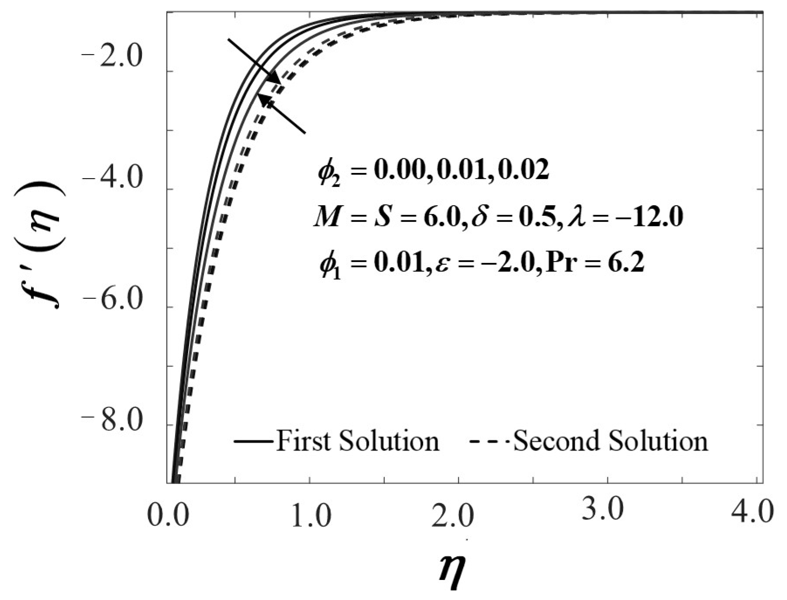
The impact of nanoparticles concentration when ϕ 2 varied is decribed in Figure 2, Figure 3, Figure 4 and Figure 5, while the value of alumina is fixed at ϕ 1 = 0.1 as the sheet shrinks. Figure 2 and Figure 3 show the characteristic of the skin friction coefficient ( f ( 0 ) ) and the velocity profiles ( f ( η ) ) as the sheet shrinks. The addition of ϕ 2 clearly enhances the f ( 0 ) tendency from Al2O3/H2O nanofluid to Al2O3–Cu/H2O hybrid nanofluid, as displayed in Figure 2. The result indicates that as f ( 0 ) increases, the frictional drag exerted upsurges and potentially slowing the boundary layer separation on the shrinking surface of Al2O3–Cu/H2O hybrid nanofluid. The velocity profiles in Figure 3 show a declining trend for the first solution, but a reversal trend for the second solution is observed.
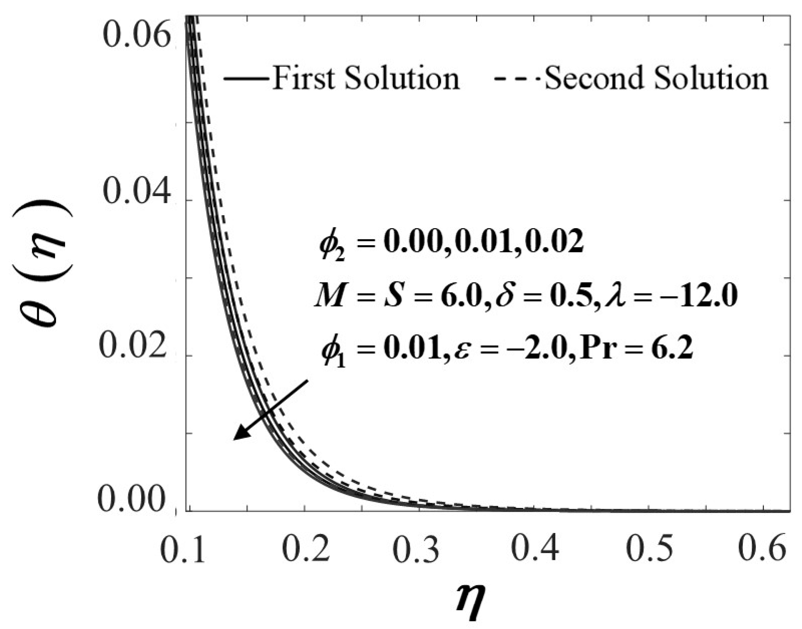
Meanwhile, Figure 4 describes the reduction in θ ( 0 ) results to an increase in ϕ 2 . The heat transfer activity in Al2O3–Cu/H2O hybrid nanofluid was noticeably slowed by a larger value of nanoparticle volume concentration. In other words, when the mass of the Al2O3–Cu/H2O hybrid nanoparticles increases, the temperature of the decreasing sheet rises, reducing the heat transfer rate. The temperature profiles or θ ( η ) reveals a reduction trend in both solutions. This may have occurred due to the simultaneous development of the suction parameter and nanoparticle volume fraction.
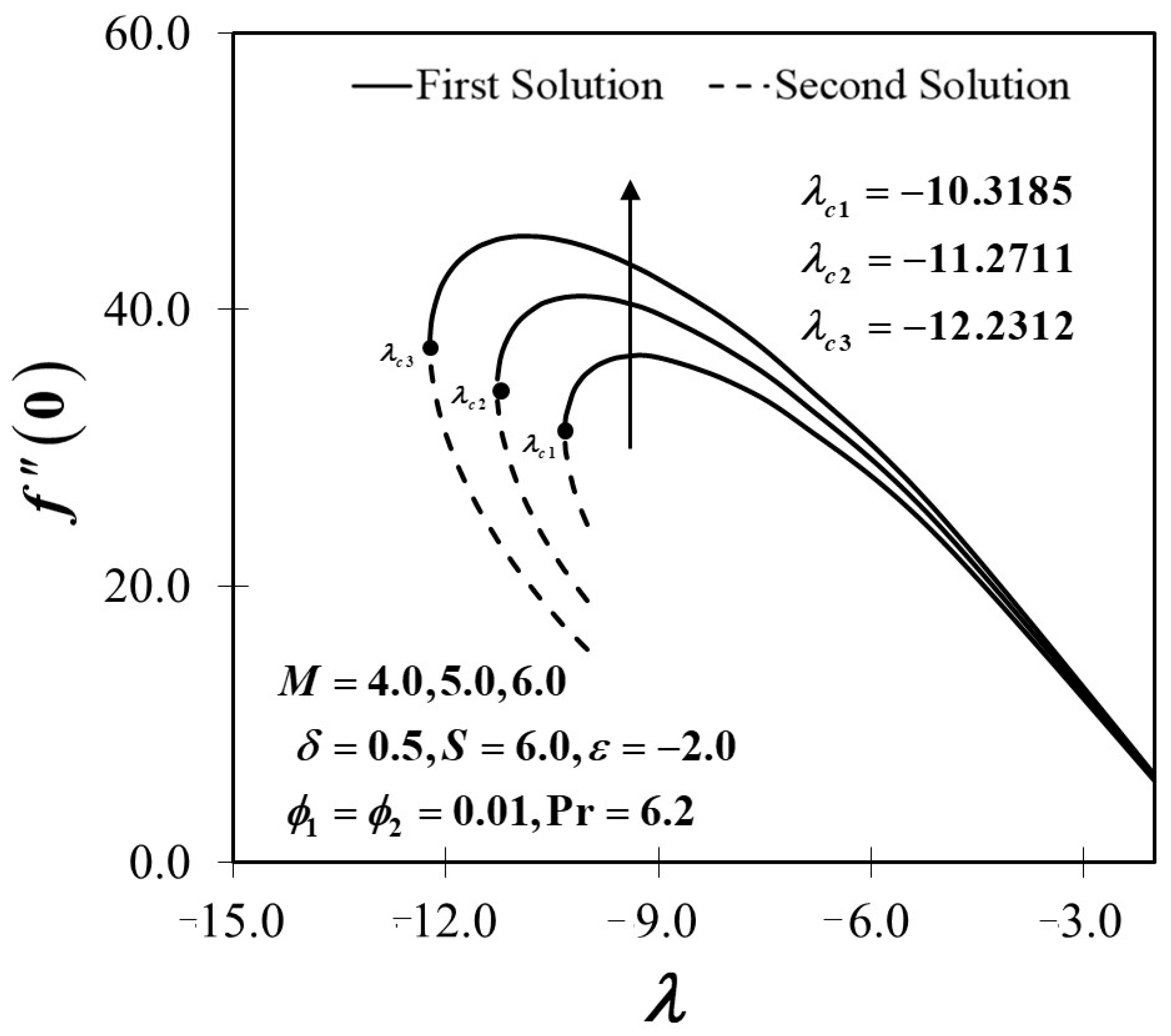
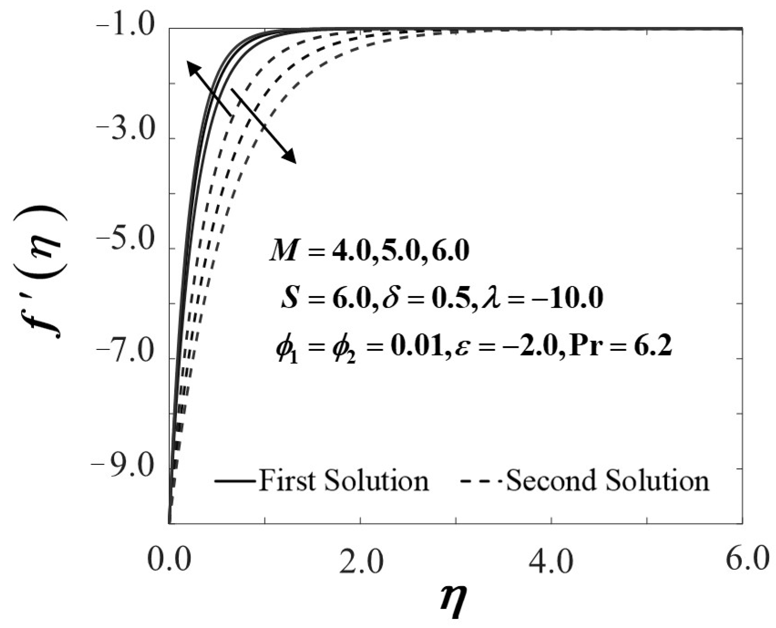
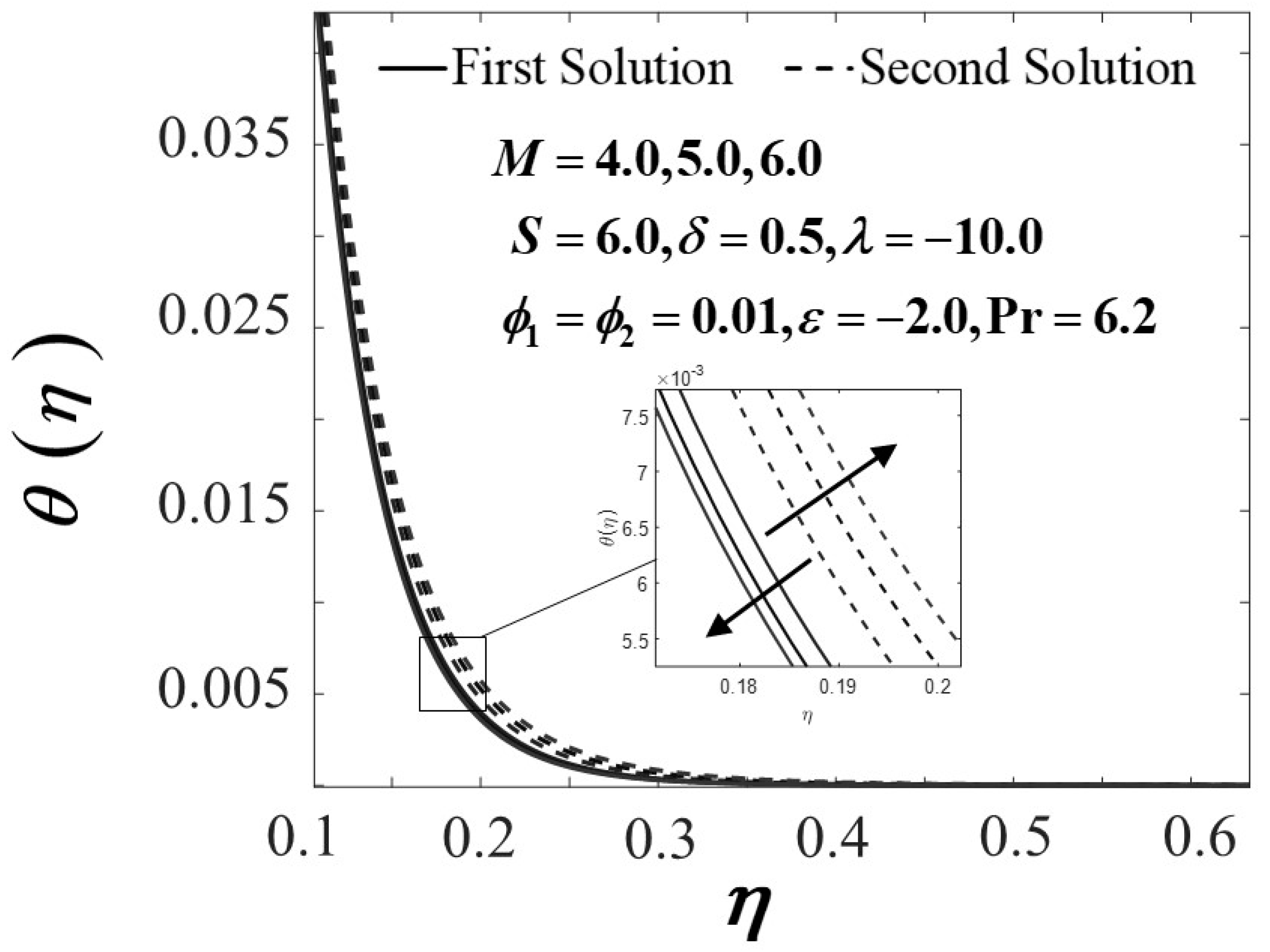
It is widely known that the Lorentz force in transport phenomena has a significant impact on fluid and heat transfer behaviour. The Lorentz force, which is heavily affected by the electromagnetic force, tends to drag the fluid velocity down. As a result, the temperature field of the working fluid increases. The findings in Figure 6, Figure 7, Figure 8 and Figure 9 support this argument which is discussed in detail afterwards. Figure 6 and Figure 7 exemplify the trend of f ( 0 ) and f ( η ) for an escalation of the magnetic parameter M . The findings reveal that higher values of M aggravate the skin friction coefficient f ( 0 ) while, the velocity profile f ( η ) of the first solution displays a reduction in the momentum boundary layer thickness, as M intensifies in the shrinking case. Conversely, the momentum boundary layer thickness in the second solution increases as the magnetic parameter is added, resulting in a reversal of the velocity profile pattern. The performance of heat transfers θ ( 0 ) and the thermal profile θ ( η ) in the influence of M is examined in Figure 8 and Figure 9. It is found that the appearance of M has a particular influence on the fluid temperature. Substantially, θ ( 0 ) boosts when the magnetic parameter is intensified (see Figure 8) attributed to the existence of the Lorentz force, as discussed earlier. The fluid temperature can also disperse from the surface to the flow owing to this force. This can be seen in the temperature distribution profile shown in Figure 9. The development and transmission of the drag force into the flow helps to increase the temperature field, which ultimately increases the thermal boundary layer thickness. In this particular study, the authors can deduce that the addition of the magnetic parameter supports a substantial improvement in heat transfer performance from the current and existing evidence. Even so, the authors would like to point out that when different control parameters are taken into account, the effects may differ.
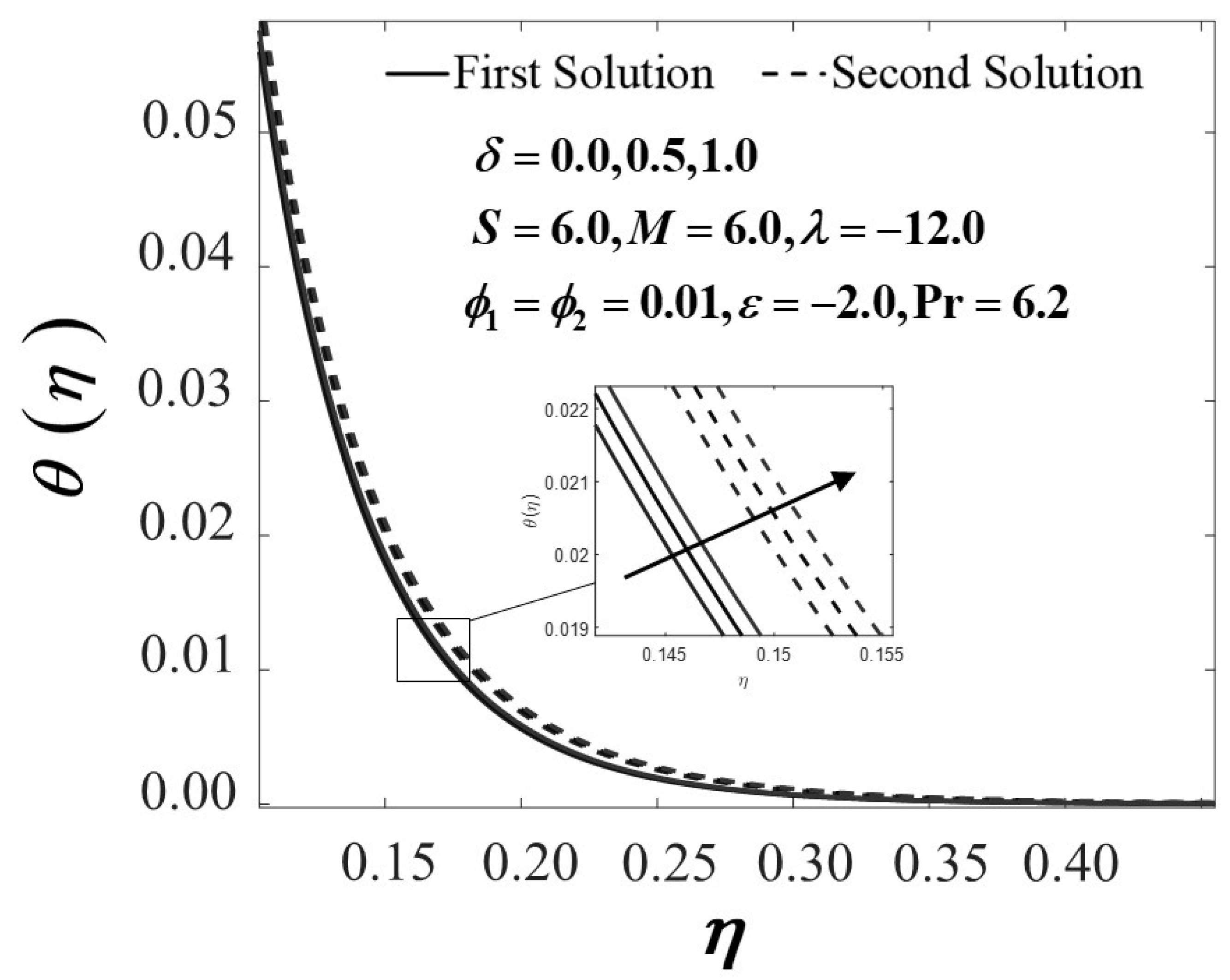
In general, the temperature field of Al2O3–Cu/H2O hybrid nanofluid will be physically improved by including the heat generation/absorption parameter, while the sheet shrinks due to the production of thermal energy at the boundary layer. Figure 10 demonstrates the temperature distribution profiles θ ( η ) of the working fluid with various values of δ . As exhibited in Figure 10, the thickness of the thermal boundary layer in the shrinking sheet grows when the heat generation ( δ > 0 ) parameter is amplified. The temperature in the boundary layer, in particular, increases as a result of heat generation ( δ > 0 ) . It is indeed worth noting that the fluid temperature peak occurs near the wall rather than on the wall at greater heat generation values. From a physical standpoint, the increase in fluid temperature is caused by the inclusion of heat generation. This phenomenon explains the growth of the thermal boundary layer thickness. The observations in the previous analyses (see Zainal et al. [48], Hayat and Nadeem [60]) indicate the same effects with the current findings.

5. Conclusions

Mathematical analysis on unsteady MHD rear stagnation point flow with a heat generation/absorption effect in Al2O3–Cu/H2O hybrid nanofluid was validated numerically in the present study. The impact of assorted operating parameters, for example, the volume fraction of nanoparticle, the MHD and heat generation/absorption parameter, were scrutinised. The outcomes suggest that dual solutions are feasible across the Al2O3–Cu/H2O hybrid nanofluid is verifiable in certain controlling parameters. However, the dual solutions occur when the sheet is shrinking. The stability analysis enables us to permit our first solution consistency, while the second solution is considered unstable. Moreover, when the magnetic parameter is induced in the operating fluid, the heat transfer performance is increased. The inclusion of the nanoparticle volume fraction enhances the skin friction coefficient in Al2O3–Cu/H2O hybrid nanofluid but declines the local Nusselt number. A recent aggregation to the heat generation factor value has donated to the development in the temperature distribution profile. As a result, the thermal boundary layer is urged to elevate, and the heat transfer performance is degraded accordingly.

Author Contributions

Article preparation, N.A.Z.; formulation and methodology, N.A.Z., R.N., K.N., and I.P.; research design, N.A.Z., R.N., K.N., and I.P.; analysis of result, N.A.Z., R.N., and K.N.; validation, R.N. and K.N.; review and editing, N.A.Z., R.N., K.N., and I.P. All authors have read and agreed to the published version of the manuscript.

Funding

This project is funded by GUP-2019-034 from Universiti Kebangsaan Malaysia.

Institutional Review Board Statement

Not applicable.

Informed Consent Statement

Not applicable.

Data Availability Statement

Not applicable.

Acknowledgments

All authors value the useful input from knowledgeable reviewers.

Conflicts of Interest

The authors declare no conflict of interest.

References

  1. Katagiri, M. On the separation of magnetohydrodynamic flow near the rear stagnation point. J. Phys. Soc. Jpn. 1969, 27, 1045–1050. [Google Scholar] [CrossRef]
  2. Mitrishkin, Y.V.; Korenev, P.S.; Kartsev, N.M.; Kuznetsov, E.A.; Prokhorov, A.A.; Patrov, M.I. Plasma magnetic cascade multiloop control system design methodology in a tokamak. Control Eng. Pract. 2019, 87, 97–110. [Google Scholar] [CrossRef]
  3. Mitryushkin, Y.V.; Korenev, P.S.; Prokhorov, A.A.; Kartsev, N.M.; Patrov, M.I. Plasma Control in Tokamaks. Part 1. Adv. Syst. Sci. Appl. 2018, 18, 26–52. [Google Scholar]
  4. De Tommasi, G. Plasma magnetic control in tokamak devices. J. Fusion Energy 2019, 38, 406–436. [Google Scholar] [CrossRef]
  5. Hartmann, J. Hg-Dynamics I: Theory of the laminar conductive liquid in a homogeneous magnetic field. K. Dan. Vidensk. Selsk. Mat. Fys. Medd. 1937, 15, 1–28. [Google Scholar]
  6. Leibovich, S. Magnetohydrodynamic flow at a rear stagnation point. J. Fluid Mech. 1967, 29, 401–413. [Google Scholar] [CrossRef]
  7. Pavlov, K.B. Magnetohydrodynamic flow of an incompressible viscous fluid caused by deformation of a plane surface. Magn. Gidrodin. 1974, 4, 146–147. [Google Scholar]
  8. Zainal, N.A.; Nazar, R.; Naganthran, K.; Pop, I. Unsteady MHD stagnation point flow-induced stretching/shrinking sheet of hybrid nanofluid by exponentially permeable. Eng. Sci. Technol. Int. J. 2021, 24, 1201–1210. [Google Scholar]
  9. Versaci, M.; Cutrupi, A.; Palumbo, A. A magneto-thermo-static study of a magneto-rheological fluid damper: A finite element analysis. IEEE Trans. Magn. 2020, 57, 1–10. [Google Scholar] [CrossRef]
  10. Seth, G.S.; Bhattacharyya, A.; Kumar, R.; Chamkha, A.J. Entropy generation in hydromagnetic nanofluid flow over a non-linear stretching sheet with Navier’s velocity slip and convective heat transfer. Phys. Fluids 2018, 30, 122003. [Google Scholar] [CrossRef]
  11. Aslani, Κ.E.; Sarris, I.E. Effect of micromagnetorotation on magnetohydrodynamic Poiseuille micropolar flow: Analytical solutions and stability analysis. J. Fluid Mech. 2021, 920, A25. [Google Scholar] [CrossRef]
  12. Hiemenz, K. Die Grenzschicht an einem in den gleichförmingen Flüssigkeitsstrom eingetauchten geraden Kreiszylinder. Dinglers Polytech J. 1911, 326, 321–324. [Google Scholar]
  13. Homann, F. Der Einfluss grosser Zähigkeit bei der Strömung um den Zylinder und um die Kugel. Z. Angew. Math. Mech. 1936, 16, 153–164. [Google Scholar] [CrossRef]
  14. Rauwendaal, C. Polymer Extrusion; Hanser Publications: Cincinnati, OH, USA, 1985. [Google Scholar]
  15. Fisher, E.G. Extrusion of Plastics; Wiley: New York, NY, USA, 1976. [Google Scholar]
  16. Proudman, I.; Johnson, K. Boundary-layer growth near a rear stagnation point. J. Fluid Mech. 1961, 12, 161–168. [Google Scholar] [CrossRef]
  17. Robins, A.; Howarth, J.A. Boundary-layer development at a two-dimensional rear stagnation point. J. Fluid Mech. 1972, 56, 161–171. [Google Scholar] [CrossRef]
  18. Howarth, J.A. A note on boundary-layer growth at a three-dimensional rear stagnation point. J. Fluid Mech. 1973, 59, 769–773. [Google Scholar] [CrossRef]
  19. Turkyilmazoglu, M.; Naganthran, K.; Pop, I. Unsteady MHD rear stagnation point flow over off-centred deformable surfaces. Int. J. Numer. Methods Heat Fluid Flow. 2017, 27, 1554–1570. [Google Scholar] [CrossRef]
  20. Khashi’ie, N.S.; Hafidzuddin, E.H.; Arifin, N.M.; Wahi, N. Stagnation point flow of hybrid nanofluid over a permeable vertical stretching/shrinking cylinder with thermal stratification effect. CFD Lett. 2020, 12, 80–94. [Google Scholar]
  21. Khashi’ie, N.S.; Arifin, N.M.; Merkin, J.H.; Yahaya, R.I.; Pop, I. Mixed convective stagnation point flow of a hybrid nanofluid toward a vertical cylinder. Int. J. Numer. Methods Heat Fluid Flow. 2021, in press. [Google Scholar] [CrossRef]
  22. Zainal, N.A.; Nazar, R.; Naganthran, K.; Pop, I. Unsteady EMHD stagnation point flow over a stretching/shrinking sheet in a hybrid Al2O3-Cu/H2O nanofluid. Int. Commun. Heat Mass Transf. 2021, 123, 105205. [Google Scholar] [CrossRef]
  23. Zainal, N.A.; Nazar, R.; Naganthran, K.; Pop, I. Unsteady MHD mixed convection flow in hybrid nanofluid at three-dimensional stagnation point. Mathematics 2021, 9, 549. [Google Scholar] [CrossRef]
  24. Smith, F.T. Steady and unsteady boundary layer separation. Annu. Rev. Fluid Mech. 1986, 18, 197–220. [Google Scholar] [CrossRef]
  25. White, F.M. Viscous Fluid Flow, 2nd ed.; McGraw-Hill: New York, NY, USA, 1991. [Google Scholar]
  26. McCroskey, W.J. Some current research in unsteady fluid dynamics—The 1976 Freeman Scholar Lecture, Trans. ASME. J. Fluid Eng. 1977, 99, 8–39. [Google Scholar] [CrossRef]
  27. Benson, R.S.; Garg, R.D.; Woollatt, D. A numerical solution of unsteady flow problems. Int. J. Mech. Sci. 1964, 6, 117–144. [Google Scholar] [CrossRef]
  28. Sears, W.R.; Telionis, D.P. Boundary-layer separation in unsteady flow. SIAM J. Appl. Math. 1975, 28, 215–235. [Google Scholar] [CrossRef]
  29. Hayat, T.; Imtiaz, M.; Alsaedi, A. Unsteady flow of nanofluid with double stratification and magnetohydrodynamics. Int. J. Heat Mass Transf. 2016, 92, 100–109. [Google Scholar] [CrossRef]
  30. Jahan, S.; Sakidin, H.; Nazar, R.; Pop, I. Unsteady flow and heat transfer past a permeable stretching/shrinking sheet in a nanofluid: A revised model with stability and regression analyses. J. Mol. Liq. 2018, 261, 550–564. [Google Scholar] [CrossRef]
  31. Zainal, N.A.; Nazar, R.; Naganthran, K.; Pop, I. Unsteady three-dimensional MHD non-axisymmetric Homann stagnation point flow of a hybrid nanofluid with stability analysis. Mathematics 2020, 8, 784. [Google Scholar] [CrossRef]
  32. Hafidzuddin, M.E.H.; Nazar, R.; Arifin, N.M.; Pop, I. Unsteady flow and heat transfer over a permeable stretching/shrinking sheet with generalised slip velocity. Int. J. Numer. Methods Heat Fluid Flow 2018, 28, 1457–1470. [Google Scholar] [CrossRef]
  33. Subhani, S.M. Nadeem, Numerical investigation of unsteady MHD flow of micropolar hybrid nanofluid in porous medium. Phys. Scr. 2019, 94, 105220. [Google Scholar] [CrossRef]
  34. Khan, U.; Waini, I.; Ishak, A.; Pop, I. Unsteady hybrid nanofluid flow over a radially permeable shrinking/stretching surface. J. Mol. Liq. 2021, 331, 115752. [Google Scholar] [CrossRef]
  35. Waini, I.; Ishak, A.; Pop, I. Unsteady hybrid nanofluid flow on a stagnation point of a permeable rigid surface. ZAMM—J. Appl. Math. Mech./Z. Angew. Math. Mech. 2020, 101, e202000193. [Google Scholar]
  36. Rahman, M.M.; Sattar, M.A. Magnetohydrodynamic convective flow of a micropolar fluid past a continuously moving vertical porous plate in the presence of heat generation/absorption. J. Heat Transf. 2006, 128, 142–152. [Google Scholar] [CrossRef]
  37. Vajravelu, K.; Hadjinicolaou, A. Heat transfer in a viscous fluid over a stretching sheet with viscous dissipation and internal heat generation. Int. Commun. Heat Mass Transf. 1993, 20, 417–430. [Google Scholar] [CrossRef]
  38. Alsaedi, A.; Awais, M.; Hayat, T. Effects of heat generation/absorption on stagnation point flow of nanofluid over a surface with convective boundary conditions. Commun. Nonlinear Sci. Numer. Simul. 2012, 17, 4210–4223. [Google Scholar] [CrossRef]
  39. Soomro, F.A.; Haq, R.U.; Al-Mdallal, Q.M.; Zhang, Q. Heat generation/absorption and nonlinear radiation effects on stagnation point flow of nanofluid along a moving surface. Results Phys. 2018, 8, 404–414. [Google Scholar] [CrossRef]
  40. Jo, E.; Park, J.H.; Park, J.; Hwang, J.; Chung, K.Y.; Nam, K.W.; Kim, S.M.; Chang, W. Different thermal degradation mechanisms: Role of aluminum in Ni-rich layered cathode materials. Nano Energy 2020, 78, 105367. [Google Scholar] [CrossRef]
  41. Berni, F.; Fontanesi, S. A 3D-CFD methodology to investigate boundary layers and assess the applicability of wall functions in actual industrial problems: A focus on in-cylinder simulations. Appl. Therm. Eng. 2020, 174, 115320. [Google Scholar] [CrossRef]
  42. Tiwari, R.K.; Das, M.K. Heat transfer augmentation in a two-sided lid-driven differentially heated square cavity utilising nanofluids. Int. J. Heat Mass Transf. 2007, 50, 2002–2018. [Google Scholar] [CrossRef]
  43. Takabi, B.; Salehi, S. Augmentation of the heat transfer performance of a sinusoidal corrugated enclosure by employing hybrid nanofluid. Adv. Mech. Eng. 2014, 6, 147059. [Google Scholar] [CrossRef]
  44. Ghalambaz, M.; Ros, N.C.; Ros, A.V.; Pop, I. Mixed convection and stability analysis of stagnation-point boundary layer flow and heat transfer of hybrid nanofluids over a vertical plate. Int. J. Numer. Methods Heat Fluid Flow. 2019, 30, 3737–3754. [Google Scholar] [CrossRef]
  45. Babu, J.R.; Kumar, K.K.; Rao, S.S. State-of-art review on hybrid nanofluids. Renew. Sustain. Energy Rev. 2017, 77, 551–565. [Google Scholar] [CrossRef]
  46. Hussain, S.; Ahmed, S.E.; Akbar, T. Entropy generation analysis in MHD mixed convection of hybrid nanofluid in an open cavity with a horizontal channel containing an adiabatic obstacle. Int. J. Heat Mass Transf. 2017, 114, 1054–1066. [Google Scholar] [CrossRef]
  47. Devi, S.S.U.; Devi, S.A. Numerical investigation of three-dimensional hybrid Cu–Al2O3/water nanofluid flow over a stretching sheet with effecting Lorentz force subject to Newtonian heating. Can. J. Phys. 2016, 94, 490–496. [Google Scholar] [CrossRef]
  48. Zainal, N.A.; Nazar, R.; Naganthran, K.; Pop, I. Heat generation/absorption effect on MHD flow of hybrid Nnanofluid over bidirectional exponential stretching/shrinking sheet. Chin. J. Phys. 2021, 69, 118–133. [Google Scholar] [CrossRef]
  49. Abu-Nada, E.; Oztop, H.F. Effects of inclination angle on natural convection in enclosures filled with Cu-water nanofluid. Int. J. Heat Fluid Flow. 2009, 30, 669–678. [Google Scholar] [CrossRef]
  50. Fang, T.; Jing, W. Closed-form analytical solutions of flow and heat transfer for an unsteady rear stagnation-point flow. Int. J. Heat Mass Transf. 2013, 62, 55–62. [Google Scholar] [CrossRef]
  51. Merkin, J.H. Mixed convection boundary layer flow on a vertical surface in a saturated porous medium. J. Eng. Math. 1980, 14, 301–313. [Google Scholar] [CrossRef]
  52. Merrill, K.; Beauchesne, M.; Previte, J.; Paullet, J.; Weidman, P. Final steady flow near a stagnation point on a vertical surface in a porous medium. Int. J. Heat Mass Transf. 2006, 49, 4681–4686. [Google Scholar] [CrossRef] [Green Version]
  53. Waini, I.; Ishak, A.; Pop, I. Unsteady flow and heat transfer past a stretching/shrinking sheet in a hybrid nanofluid. Int. J. Heat Mass Transf. 2019, 136, 288–297. [Google Scholar] [CrossRef]
  54. Zainal, N.A.; Nazar, R.; Naganthran, K.; Pop, I. Stability analysis of MHD hybrid nanofluid flow over a stretching/shrinking sheet with quadratic velocity. Alex. Eng. J. 2020, 60, 915–926. [Google Scholar] [CrossRef]
  55. Weidman, P.D.; Kubitschek, D.G.; Davis, A.M.J. The effect of transpiration on self-similar boundary layer flow over moving surfaces. Int. J. Eng. Sci. 2006, 44, 730–737. [Google Scholar] [CrossRef]
  56. Harris, S.D.; Ingham, D.B.; Pop, I. Mixed convection boundary-layer flow near the stagnation point on a vertical surface in a porous medium: Brinkman model with slip. Transp. Porous Media 2009, 77, 267–285. [Google Scholar] [CrossRef]
  57. Bhattacharyya, K. Dual solutions in boundary layer stagnation-point flow and mass transfer with chemical reaction past a stretching/shrinking sheet. Int. Commun. Heat Mass Transf. 2011, 38, 917–922. [Google Scholar] [CrossRef]
  58. Arifin, N.M.; Nazar, R.; Pop, I. Non-Isobaric Marangoni boundary layer flow for Cu, Al2O3 and TiO2 nanoparticles in a water-based fluid. Meccanica 2011, 46, 833–843. [Google Scholar] [CrossRef]
  59. Suresh, S.; Venkitaraj, K.P.; Selvakumar, P. Synthesis, characterisation of Al2O3-Cu nanocomposite powder and water-based nanofluids. Adv. Mater. Res. 2011, 328, 1560–1567. [Google Scholar] [CrossRef]
  60. Hayat, T.; Nadeem, S. Heat transfer enhancement with Ag–CuO/water hybrid nanofluid. Results Phys. 2017, 7, 2317–2324. [Google Scholar] [CrossRef]
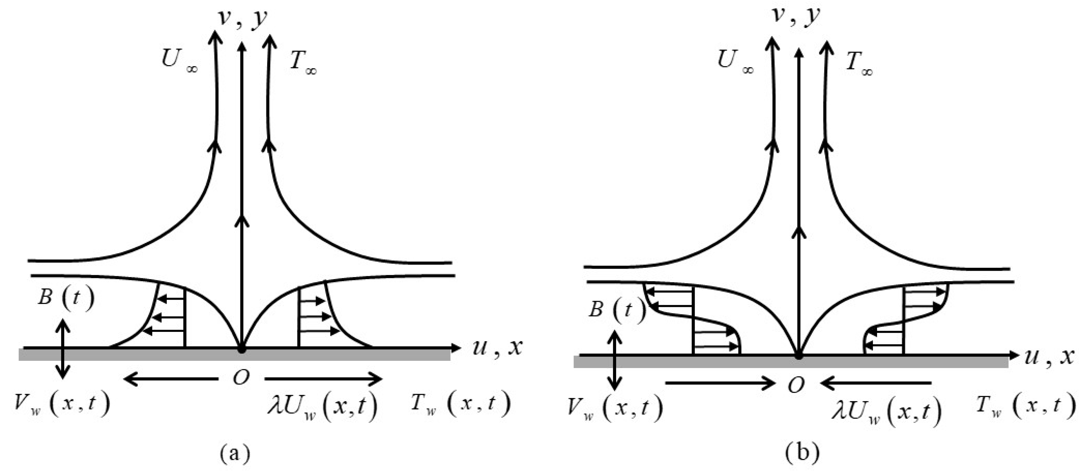
Figure 1. Physical models and coordinate systems: (a) stretching sheet (b) shrinking sheet.
Mathematics 09 02428 g001
Figure 2. f ( 0 ) against λ by various ϕ 2 .
Mathematics 09 02428 g002
Figure 3. f ( η ) with various ϕ 2 when λ = 12.0 .
Mathematics 09 02428 g003
Figure 4. θ ( 0 ) against λ by various ϕ 2 .
Mathematics 09 02428 g004
Figure 5. θ ( η ) with various ϕ 2 when λ = 12.0 .
Mathematics 09 02428 g005
Figure 6. f ( 0 ) against λ by various M .
Mathematics 09 02428 g006
Figure 7. f ( η ) with various M when λ = 10.0 .
Mathematics 09 02428 g007
Figure 8. θ ( 0 ) against λ by various M .
Mathematics 09 02428 g008
Figure 9. θ ( η ) with various M when λ = 10.0 .
Mathematics 09 02428 g009
Figure 10. θ ( η ) with δ = 0.0 , 0.5 , 1.0 .
Mathematics 09 02428 g010
Table 1. The H2O, Al2O3 and Cu thermophysical properties (see Abu Nada and Oztop [49]).
Physical Properties k ( W / m K ) ρ ( k g / m 3 ) C p ( J / k g K )
H2O0.613997.14179
Al2O3403970765
Cu4008933385
Table 2. The alumina–copper/water (Al2O3–Cu/H2O) correlation coefficient (Takabi and Salehi [43]; Ghalambaz et al. [44]).
PropertiesAl2O3–Cu/H2O
Density ρ h n f = ( 1 ϕ h n f ) ρ f + ϕ 1 ρ s 1 + ϕ 2 ρ s 2
Dynamic viscosity μ h n f = μ f / ( 1 ϕ h n f ) 2.5
Thermal capacity ( ρ C p ) h n f = ( 1 ϕ h n f ) ( ρ C p ) f + ϕ 1 ( ρ C p ) s 1 + ϕ 2 ( ρ C p ) s 2
Thermal conductivity k h n f k f = [ ( ϕ 1 k s 1 + ϕ 2 k s 2 ϕ h n f ) + 2 k f + 2 ( ϕ 1 k s 1 + ϕ 2 k s 2 ) 2 ϕ h n f k f ( ϕ 1 k s 1 + ϕ 2 k s 2 ϕ h n f ) + 2 k f ( ϕ 1 k s 1 + ϕ 2 k s 2 ) + ϕ h n f k f ]
Electrical conductivity σ h n f σ f = [ ( ϕ 1 σ s 1 + ϕ 2 σ s 2 ϕ h n f ) + 2 σ f + 2 ( ϕ 1 σ s 1 + ϕ 2 σ s 2 ) 2 ϕ h n f σ f ( ϕ 1 σ s 1 + ϕ 2 σ s 2 ϕ h n f ) + 2 σ f ( ϕ 1 σ s 1 + ϕ 2 σ s 2 ) + ϕ h n f σ f ]
Table 3. Approximation values of Re x 1 / 2 C f by certain values of λ when ε = M = δ = S = ϕ 1 = ϕ 2 = 0 .
λPresent ResultTurkyilmazoglu et al. [19]Bhattacharyya [57]
First SolutionSecond SolutionFirst SolutionSecond SolutionFirst SolutionSecond Solution
−0.251.4022408-1.4022408-1.4022405-
−0.501.4956698-1.4956670-1.4956697-
−0.751.4892982-1.4892982-1.4892981-
−1.001.32881690.00000001.32881680.00000001.32881690.0000000
−1.151.08223120.11670211.08223120.11670211.08223160.1167023
−1.200.93247330.23364970.93247330.23364970.93247280.2336491
−1.24650.58428170.55429620.58428130.55429470.58429150.5542856
−1.246570.57452570.56401250.57745250.56400810.57452680.5639987
Table 4. Values of Re x 1 / 2 C f and Re x 1 / 2 N u x for Al2O3–Cu/water hybrid nanofluid when Pr = 6.2 , ϕ 1 = 0.01 , S = 6.0 and λ = 10 for various values of ϕ 2 , M and δ .
ϕ 2 M δ Al2O3–Cu/Water Hybrid Nanofluid ( ϕ 1   =   0.01 )
Re x 1 / 2 C f Re x 1 / 2 N u x
0.006.00.541.028633656033.2812323540
0.01 44.479457025033.1259684480
0.02 47.997340543032.9737922260
0.014.0 35.446314750033.0027615510
5.0 40.934760449033.0792778990
6.0 44.479457025033.1259684480
0.0-33.2417593770
0.5-33.1259684480
1.0-33.0091507970
Table 5. The smallest eigenvalues ω 1 with assorted λ .
λ First Solution ω1Second Solution ω1
−102.0570−1.8571
−10.30.4956−0.4836
−10.310.3416−0.3359
−10.3180.2560−0.2527
−10.31830.2001−0.1981
−10.31850.1210−0.1203
Publisher’s Note: MDPI stays neutral with regard to jurisdictional claims in published maps and institutional affiliations.