

Integrating Fused Deposition Modeling and Melt Electrowriting for Engineering Branched Vasculature


Abstract
:
1. Introduction
2. Materials and Methods
2.1. Materials
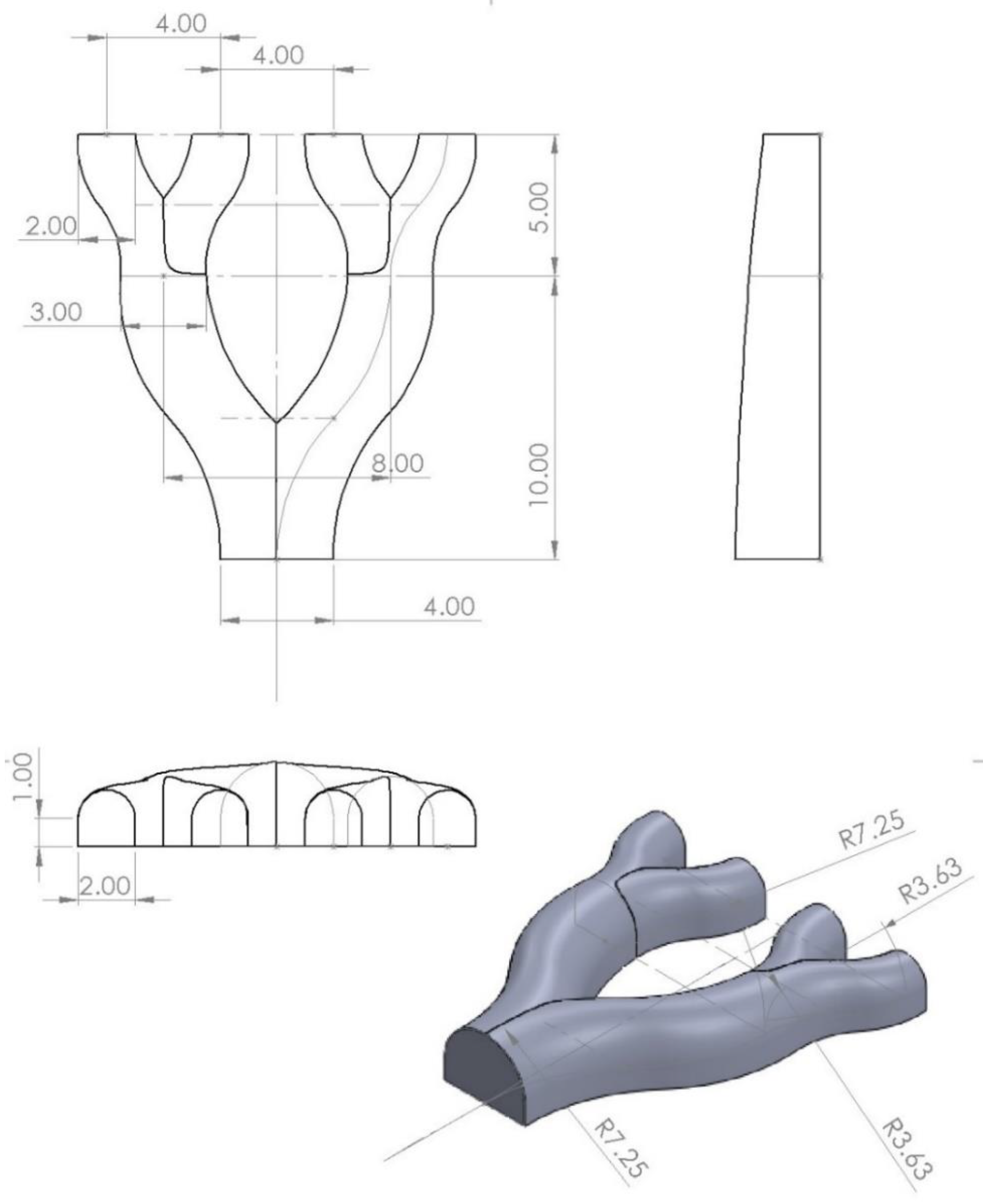
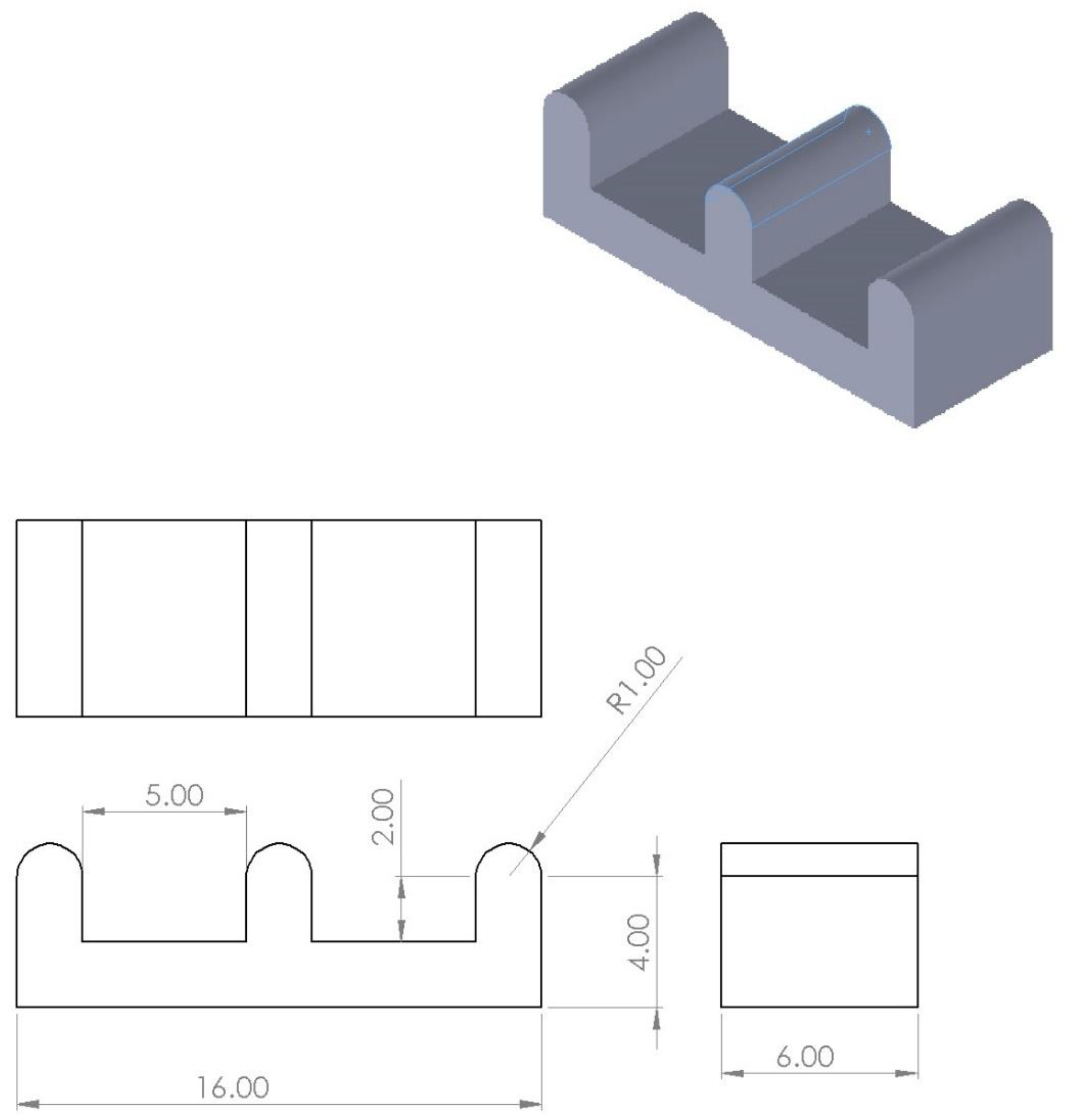
2.2. Mold Design
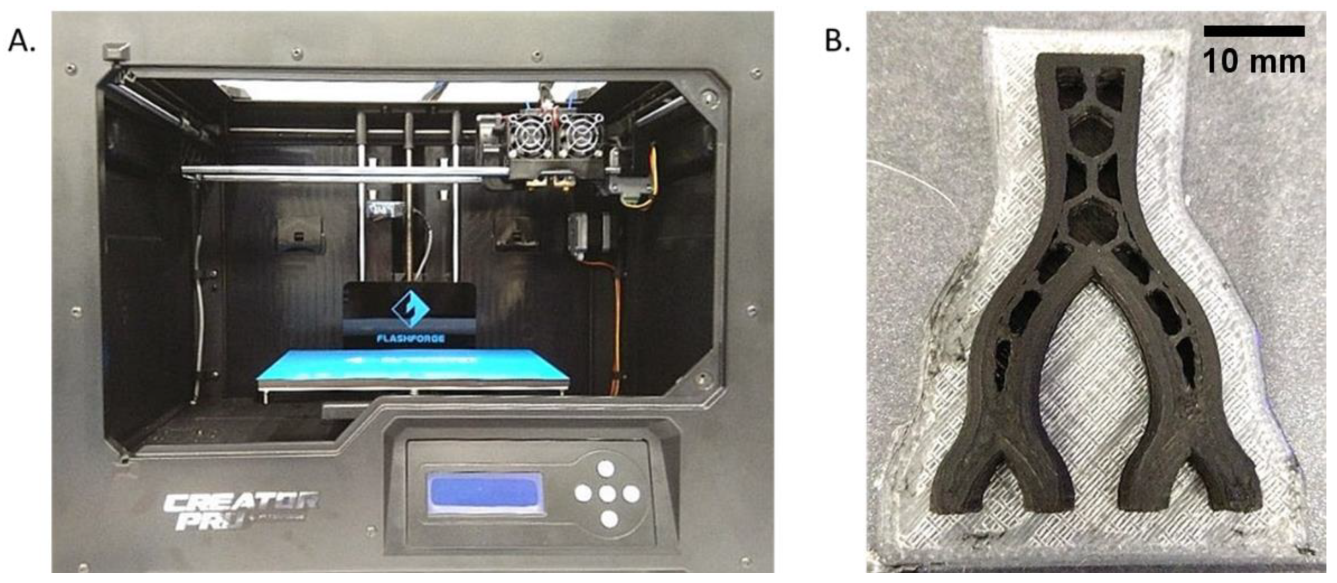
2.3. Mold 3D Fabrication
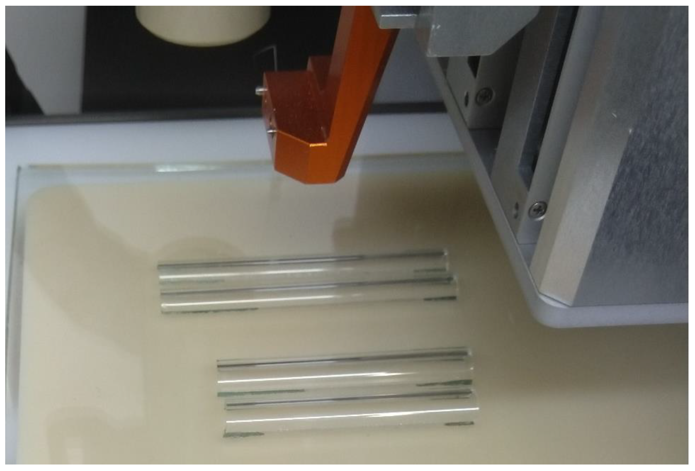
2.4. Melt Electrowriting 3D Printing
2.5. Scaffold Analysis
2.5.1. Pore Properties
2.5.2. Mechanical Strength
2.5.3. In Vitro Cell Studies
3. Results
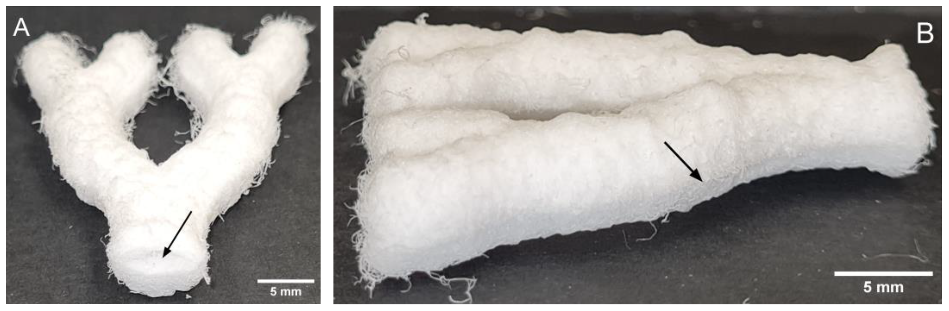
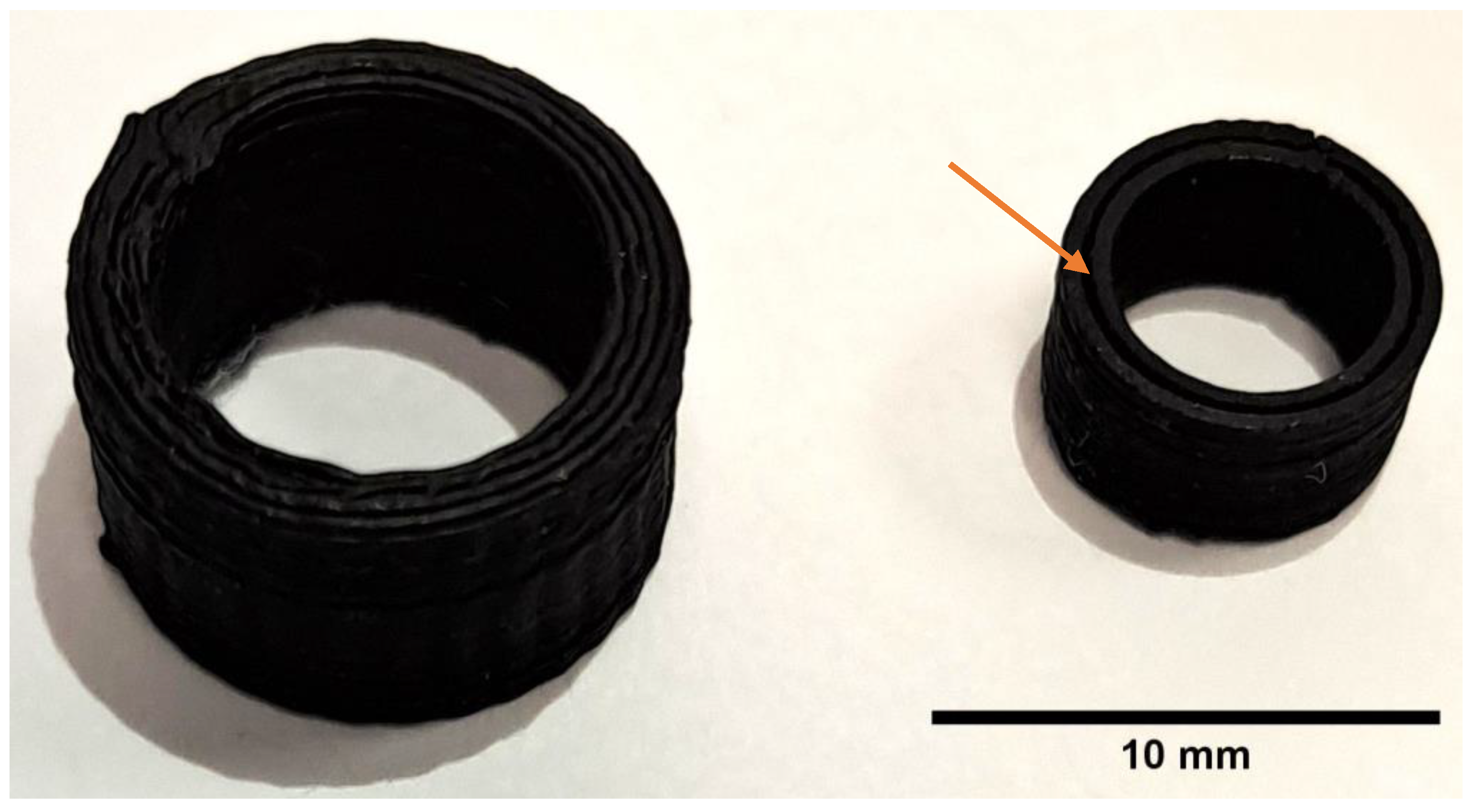
3.1. Mold Fabrication
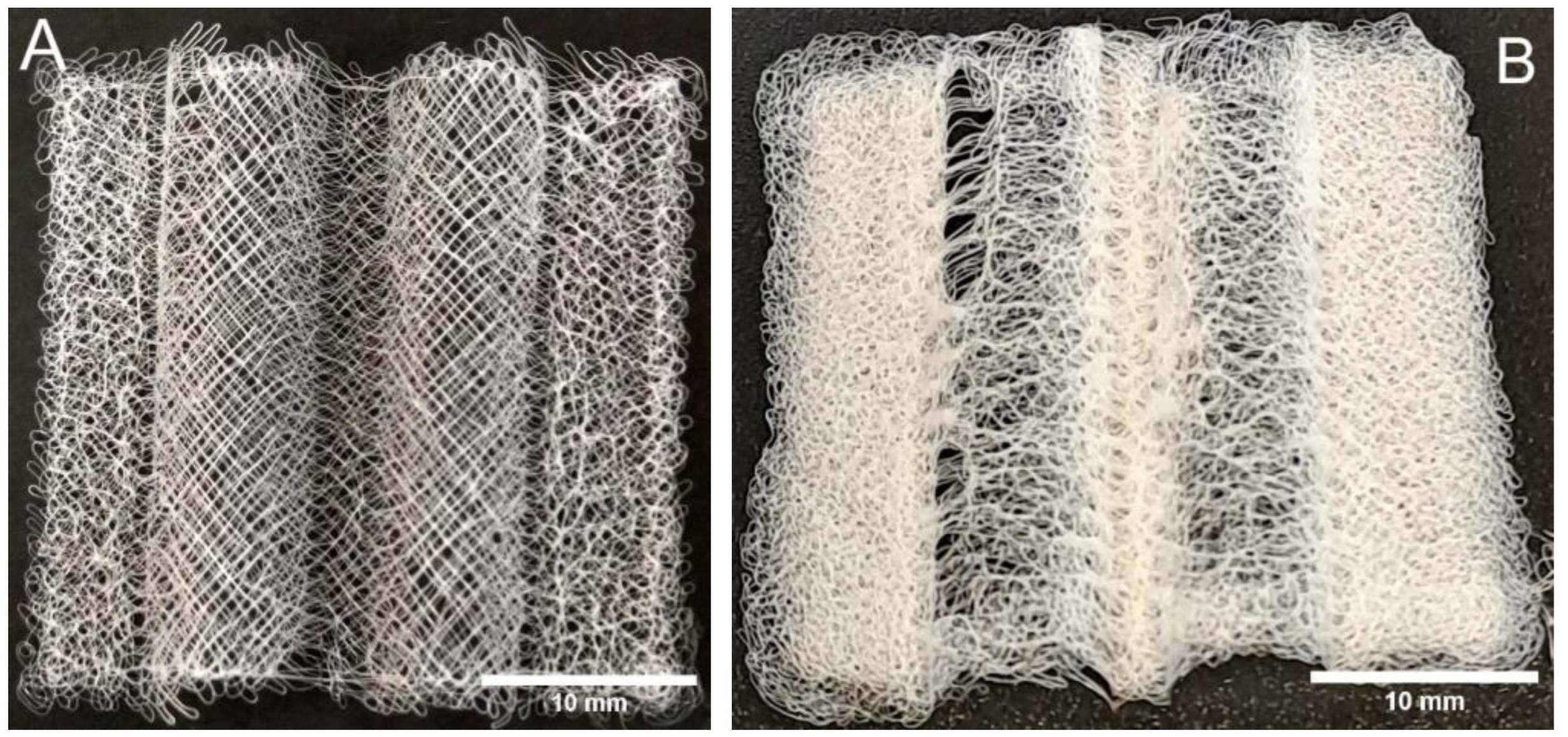
3.2. MEW 3D Printing
3.3. Scaffold Analysis
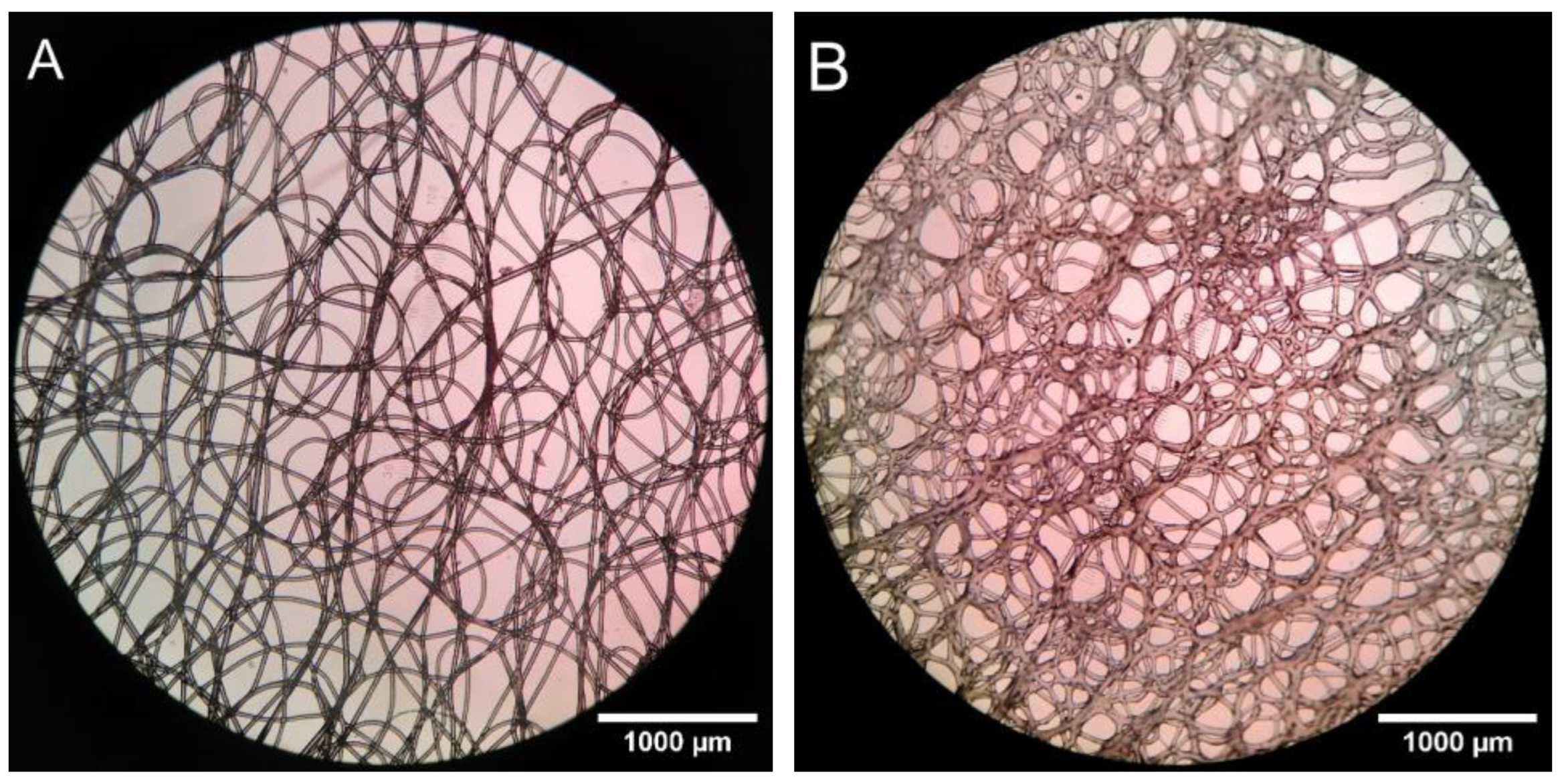
3.3.1. Pore Properties
3.3.2. Mechanical Strength
3.3.3. In Vitro Cell Studies
4. Discussion
5. Conclusions
Author Contributions
Funding
Institutional Review Board Statement
Informed Consent Statement
Data Availability Statement
Acknowledgments
Conflicts of Interest
References
- Brooks-Richards, T.L.; Paxton, N.C.; Allenby, M.C.; Woodruff, M.A. Dissolvable 3D Printed PVA Moulds for Melt Electrowriting Tubular Scaffolds with Patient-Specific Geometry. Mater. Des. 2022, 215, 110466. [Google Scholar] [CrossRef]
- Yoshida, M.; Turner, P.R.; Ali, M.A.; Cabral, J.D. Three-Dimensional Melt-Electrowritten Polycaprolactone/Chitosan Scaffolds Enhance Mesenchymal Stem Cell Behavior. ACS Appl. Biomater. 2021, 4, 1319–1329. [Google Scholar] [CrossRef]
- Brown, T.D.; Slotosch, A.; Thibaudeau, L.; Taubenberger, A.; Loessner, D.; Vaquette, C.; Dalton, P.D.; Hutmacher, D.W. Design and Fabrication of Tubular Scaffolds via Direct Writing in a Melt Electrospinning Mode. Biointerphases 2012, 7, 13. [Google Scholar] [CrossRef]
- Liashenko, I.; Hrynevich, A.; Dalton, P.D. Designing Outside the Box: Unlocking the Geometric Freedom of Melt Electrowriting Using Microscale Layer Shifting. Adv. Mater. 2020, 32, 2001874. [Google Scholar] [CrossRef] [PubMed]
- Kumar, V.A.; Brewster, L.P.; Caves, J.M.; Chaikof, E.L. Tissue Engineering of Blood Vessels: Functional Requirements, Progress, and Future Challenges. Cardiovasc. Eng. Tech. 2011, 2, 137–148. [Google Scholar] [CrossRef] [PubMed]
- Zhu, M.; Wang, Z.; Zhang, J.; Wang, L.; Yang, X.; Chen, J.; Fan, G.; Ji, S.; Xing, C.; Wang, K.; et al. Circumferentially Aligned Fibers Guided Functional Neoartery Regeneration In Vivo. Biomaterials 2015, 61, 85–94. [Google Scholar] [CrossRef] [PubMed]
- Tirado-Garcia, I.; Garcia-Gonzalez, D.; Garzon-Hernandez, S.; Rusinek, A.; Robles, G.; Martinez-Tarifa, J.M.; Arias, A. Conductive 3D Printed PLA Composites: On the Interplay of Mechanical, Electrical and Thermal Behaviours. Compos. Struct. 2021, 265, 113744. [Google Scholar] [CrossRef]
- Jaycar Electronics New Zealand. Conductive PLA Filament for 3D Printer 1.75 MM 250 G. Available online: https://www.jaycar.co.nz/conductive-pla-filament-for-3d-printer-1-75mm-250g/p/TL4142 (accessed on 17 May 2023).
- Kaye & Laby Online. Tables of Physical & Chemical Constants. 2.7.9 Physical Properties of Sea Water. In Tables of Physical & Chemical Constants, 16th ed.; Kaye & Laby Online: Hatfield, UK, 2018. [Google Scholar]
- ECRI. Polycaprolactone (PCL) Safety Profile; U.S. FDA Centre for Devices and Radiological Health: Silver Spring, MD, USA, 2021. [Google Scholar]
- Turner, P.R.; Yoshida, M.; Ali, M.A.; Cabral, J.D. Melt Electrowritten Sandwich Scaffold Technique Using Sulforhodamine to Monitor Stem Cell Behavior. Tissue Eng. Part C Methods 2020, 26, 519–527. [Google Scholar] [CrossRef]
- de Valence, S.; Tille, J.-C.; Mugnai, D.; Mrowczynski, W.; Gurny, R.; Möller, M.; Walpoth, B.H. Long Term Performance of Polycaprolactone Vascular Grafts in a Rat Abdominal Aorta Replacement Model. Biomaterials 2012, 33, 38–47. [Google Scholar] [CrossRef]
- Hewitt, E.; Mros, S.; Mcconnell, M.; Cabral, J.; Ali, A. Melt-Electrowriting with Novel Milk Protein/PCL Biomaterials for Skin Regeneration. Biomed. Mater. 2019, 14, 055013. [Google Scholar] [CrossRef]
- Dassault Systemes (Suresnes, France) SOLIDWORKS 2019. (Ver 2019, Service Pack 0). Available online: https://www.solidworks.com/ (accessed on 24 May 2021).
- FlashForge FlashPrint 2016 (Zhejian, China). (ver. 3.10.0). Available online: https://www.flashforge.com/product-detail/40 (accessed on 11 February 2022). (ver. 3.10.0).
- Griffiths, D.J. Introduction to Electrodynamics; Pearson Prentice Hall: London, UK, 1999; ISBN 0-13-805326-X. [Google Scholar]
- Matula, R.A. Electrical Resistivity of Copper, Gold, Palladium, and Silver. J. Phys. Chem. Ref. Data 1979, 8, 1147–1298. [Google Scholar] [CrossRef]
- Stichting Blender Foundation Blender—A 3D Modelling and Rendering Package 2021 (Amsterdam, Netherlands). (ver 3.4). Available online: http://www.blender.org (accessed on 8 March 2022). (ver 3.4).
- Thorsnes, Q. An Exploration of Melt-Electrowriting and Fused Deposition Modelling for Tissue Engineering Blood Vessels. Master’s Thesis, University of Otago, Dunedin, New Zealand, 2023. [Google Scholar]
- GeSiM. GeSiM Robotics Overview Original Operating Instructions; GeSiM: Radeberg, Germany, 2018. [Google Scholar]
- Schindelin, J.; Arganda-Carreras, I.; Frise, E.; Kaynig, V.; Longair, M.; Pietzsch, T.; Preibisch, S.; Rueden, C.; Saalfeld, S.; Schmid, B.; et al. Fiji: An Open-Source Platform for Biological-Image Analysis. Nat. Methods 2012, 9, 676–682. [Google Scholar] [CrossRef]
- Howard, C.V.; Reed, M.G. Unbiased Stereology, 2nd ed.; Garland Science/BIOS Scienftific Publishers: New York, NY, USA, 2005; ISBN 185996/0898. [Google Scholar]
- Gundersen, H.J.G.; Bagger, P.; Bendtsen, T.F.; Evans, S.M.; Korbo, L.; Marcussen, N.; MØLler, A.; Nielsen, K.; Nyengaard, J.R.; Pakkenberg, B.; et al. The New Stereological Tools: Disector, Fractionator, Nucleator and Point Sampled Intercepts and Their Use in Pathological Research and Diagnosis. APMIS 1988, 96, 857–881. [Google Scholar] [CrossRef] [PubMed]
- Hwang, P.T.J.; Murdock, K.; Alexander, G.C.; Salaam, A.D.; Ng, J.I.; Lim, D.-J.; Dean, D.; Jun, H.-W. Poly(ε-Caprolactone)/Gelatin Composite Electrospun Scaffolds with Porous Crater-like Structures for Tissue Engineering. J. Biomed. Mater. Res. Part A 2016, 104, 1017–1029. [Google Scholar] [CrossRef]
- Raja, I.S.; Lee, S.H.; Kang, M.S.; Hyon, S.-H.; Selvaraj, A.R.; Prabakar, K.; Han, D.-W. The Predominant Factor Influencing Cellular Behavior on Electrospun Nanofibrous Scaffolds: Wettability or Surface Morphology? Mater. Des. 2022, 216, 110580. [Google Scholar] [CrossRef]
- Kade, J.C.; Dalton, P.D. Polymers for Melt Electrowriting. Adv. Healthc. Mater. 2021, 10, 2001232. [Google Scholar] [CrossRef] [PubMed]
- Mitra, A. Fundamentals of Quality Control and Improvement, 2nd ed.; Tucker, T., Anderson, N., Regan, A., Eds.; Prentice-Hall: Saddle River, NJ, USA, 1998; ISBN 0-13-645086-5. [Google Scholar]
- Devillard, C.D.; Marquette, C.A. Vascular Tissue Engineering: Challenges and Requirements for an Ideal Large Scale Blood Vessel. Front. Bioeng. Biotechnol. 2021, 9, 913. [Google Scholar] [CrossRef] [PubMed]
- Kelnar, I.; Kratochvíl, J.; Kaprálková, L.; Zhigunov, A.; Nevoralová, M. Graphite Nanoplatelets-Modified PLA/PCL: Effect of Blend Ratio and Nanofiller Localization on Structure and Properties. J. Mech. Behav. Biomed. Mater. 2017, 71, 271–278. [Google Scholar] [CrossRef] [PubMed]
- Donik, Ž.; Nečemer, B.; Vesenjak, M.; Glodež, S.; Kramberger, J. Computational Analysis of Mechanical Performance for Composite Polymer Biodegradable Stents. Materials 2021, 14, 6016. [Google Scholar] [CrossRef]
- Shahverdi, M.; Seifi, S.; Akbari, A.; Mohammadi, K.; Shamloo, A.; Movahhedy, M.R. Melt Electrowriting of PLA, PCL, and Composite PLA/PCL Scaffolds for Tissue Engineering Application. Sci. Rep. 2022, 12, 19935. [Google Scholar] [CrossRef] [PubMed]
- Rickel, A.P.; Deng, X.; Engebretson, D.; Hong, Z. Electrospun Nanofiber Scaffold for Vascular Tissue Engineering. Mater. Sci. Eng. C 2021, 129, 112373. [Google Scholar] [CrossRef] [PubMed]
- Kim, J.J.; Hou, L.; Huang, N.F. Vascularization of Three-Dimensional Engineered Tissues for Regenerative Medicine Applications. Acta Biomater. 2016, 41, 17–26. [Google Scholar] [CrossRef] [PubMed]
- Rabionet, M.; Guerra, A.J.; Puig, T.; Ciurana, J. 3D-Printed Tubular Scaffolds for Vascular Tissue Engineering. Procedia CIRP 2018, 68, 352–357. [Google Scholar] [CrossRef]
- Weinberg, C.B.; Bell, E. A Blood Vessel Model Constructed from Collagen and Cultured Vascular Cells. Science 1986, 231, 397–400. [Google Scholar] [CrossRef] [PubMed]
- Niklason, L.E.; Langer, R.S. Advances in Tissue Engineering of Blood Vessels and Other Tissues. Transpl. Immunol. 1997, 5, 303–306. [Google Scholar] [CrossRef] [PubMed]
- Huang, A.H.; Balestrini, J.L.; Udelsman, B.V.; Zhou, K.C.; Zhao, L.; Ferruzzi, J.; Starcher, B.C.; Levene, M.J.; Humphrey, J.D.; Niklason, L.E. Biaxial Stretch Improves Elastic Fiber Maturation, Collagen Arrangement, and Mechanical Properties in Engineered Arteries. Tissue Eng. Part. C Methods 2016, 22, 524–533. [Google Scholar] [CrossRef]
- Kirkton, R.D.; Santiago-Maysonet, M.; Lawson, J.H.; Tente, W.E.; Dahl, S.L.M.; Niklason, L.E.; Prichard, H.L. Bioengineered Human Acellular Vessels Recellularize and Evolve into Living Blood Vessels after Human Implantation. Sci. Transl. Med. 2019, 11, eaau6934. [Google Scholar] [CrossRef]
- Iwasaki, K.; Kojima, K.; Kodama, S.; Paz, A.C.; Chambers, M.; Umezu, M.; Vacanti, C.A. Bioengineered Three-Layered Robust and Elastic Artery Using Hemodynamically-Equivalent Pulsatile Bioreactor. Circulation 2008, 118, S52–S57. [Google Scholar] [CrossRef]
- Centola, M.; Rainer, A.; Spadaccio, C.; Porcellinis, S.D.; Genovese, J.A.; Trombetta, M. Combining Electrospinning and Fused Deposition Modeling for the Fabrication of a Hybrid Vascular Graft. Biofabrication 2010, 2, 014102. [Google Scholar] [CrossRef]
- Farrugia, B.L.; Brown, T.D.; Upton, Z.; Hutmacher, D.W.; Dalton, P.D.; Dargaville, T.R. Dermal Fibroblast Infiltration of Poly(ε-Caprolactone) Scaffolds Fabricated by Melt Electrospinning in a Direct Writing Mode. Biofabrication 2013, 5, 025001. [Google Scholar] [CrossRef]
- Niklason, L.E.; Gao, J.; Abbott, W.M.; Hirschi, K.K.; Houser, S.; Marini, R.; Langer, R. Functional Arteries Grown in Vitro. Science 1999, 284, 489–493. [Google Scholar] [CrossRef] [PubMed]
- Shin’oka, T.; Matsumura, G.; Hibino, N.; Naito, Y.; Watanabe, M.; Konuma, T.; Sakamoto, T.; Nagatsu, M.; Kurosawa, H. Midterm Clinical Result of Tissue-Engineered Vascular Autpgrafts Seeded with Autologous Bone Marrow Cells. J. Thorac. Cardiovasc. Surg. 2005, 129, 1330–1338. [Google Scholar] [CrossRef] [PubMed]
- Brennan, M.P.; Dardik, A.; Hibino, N.; Roh, J.D.; Nelson, G.N.; Papademitris, X.; Shinoka, T.; Breuer, C.K. Tissue Engineered Vascular Grafts Demonstrate Evidence of Growth and Development When Implanted in a Juvenile Animal Model. Ann. Surg. 2008, 248, 370–377. [Google Scholar] [CrossRef] [PubMed]
- Dalton, P.D.; Woodfield, T.B.F.; Mironov, V.; Groll, J. Advances in Hybrid Fabrication toward Hierarchical Tissue Constructs. Adv. Sci. 2020, 7, 1902953. [Google Scholar] [CrossRef] [PubMed]
- Afghah, F.; Dikyol, C.; Altunbek, M.; Koc, B. Biomimicry in Bio-Manufacturing: Developments in Melt Electrospinning Writing Technology Towards Hybrid Biomanufacturing. Appl. Sci. 2019, 9, 3540. [Google Scholar] [CrossRef]
- Detta, N.; Errico, C.; Dinucci, D.; Puppi, D.; Clarke, D.A.; Reilly, G.C.; Chiellini, F. Novel Electrospun Polyurethane/Gelatin Composite Meshes for Vascular Grafts. J. Mater. Sci. Mater. Med. 2010, 21, 1761–1769. [Google Scholar] [CrossRef]
- Hasan, A.; Memic, A.; Annabi, N.; Hossain, M.; Paul, A.; Dokmeci, M.R.; Dehghani, F.; Khademhosseini, A. Electrospun Scaffolds for Tissue Engineering of Vascular Grafts. Acta Biomater. 2014, 10, 11–25. [Google Scholar] [CrossRef]
- Rocco, K.A.; Maxfield, M.W.; Best, C.A.; Dean, E.W.; Breuer, C.K. In Vivo Applications of Electrospun Tissue-Engineered Vascular Grafts: A Review. Tissue Eng. Part. B Rev. 2014, 20, 628–640. [Google Scholar] [CrossRef]
- Weekes, A.; Barnikowski, N.; Pinto, N.; Jenkins, J. Biofabrication of Small Diameter Tissue-Engineered Vascular Grafts. Acta Biomater. 2022, 138, 92–111. [Google Scholar] [CrossRef]
- Rahmatabadi, D.; Soltanmohammadi, K.; Pahlavani, M.; Aberoumand, M.; Soleyman, E.; Ghasemi, I.; Baniassadi, M.; Abrinia, K.; Bodaghi, M.; Baghani, M. Shape Memory Performance Assessment of FDM 3D Printed PLA-TPU Composites by Box-Behnken Response Surface Methodology. Int. J. Adv. Manuf. Technol. 2023, 127, 935–950. [Google Scholar] [CrossRef]
- Soleyman, E.; Aberoumand, M.; Soltanmohammadi, K.; Rahmatabadi, D.; Ghasemi, I.; Baniassadi, M.; Abrinia, K.; Baghani, M. 4D Printing of PET-G via FDM Including Tailormade Excess Third Shape. Manuf. Lett. 2022, 33, 1–4. [Google Scholar] [CrossRef]
- Criado Gonzalez, M.; Dominguez-Alfaro, A.; Lopez-Larrea, N.; Alegret, N.; Mecerreyes, D. Additive Manufacturing of Conducting Polymers: Recent Advances, Challenges, and Opportunities. ACS Appl. Polym. Mater. 2021, 3, 2865–2883. [Google Scholar] [CrossRef] [PubMed]


| Print Speed (mm s−1) | Nozzle Temperature (°C) | Bed Temperature (°C) | Infill (%) |
|---|---|---|---|
| 70 | 205 | 50 | 30, hexagonal |
| Strand Separation (mm) | TCartridge (°C) | Voltage (kV) | z-Spacing (mm) | Nozzle Speed (mm s−1) | PCartridge (kPa) | Infill Angle Change (°) |
|---|---|---|---|---|---|---|
| 0.4 | 90 | 20 | 15 | 20 | 20 | 85 |
| Pore Statistic | Median Size (µm) | σsize (µm) | Median Volume (nL) | σvolume (nL) |
|---|---|---|---|---|
| Glass sampling 1 | 170 | 113 | 5.14 | 24.25 |
| Glass sampling 2 | 165 | 110 | 4.72 | 24.06 |
| Conductive Branch | 115 | 71 | 1.39 | 10.28 |
| Printing Surface | Median, Glass | σGlass | Median, cPLA | σcPLA |
|---|---|---|---|---|
| Pore Volume Fraction (%) | 48.07 | 2.33 | 29.47 | 4.46 |
| Mass (mg) | Volume (mm3) | Density (kg m−3) | Porosity (%) |
|---|---|---|---|
| 82.0 ± 0.1 | 328 ± 1 | 250 ± 2 | 77.6 ± 0.5 |
| 62.4 ± 0.1 | 246 ± 1 | 254 ± 2 | 77.2 ± 0.5 |
| 58.8 ± 0.1 | 226 ± 1 | 260 ± 2 | 76.7 ± 0.5 |
| 79.5 ± 0.1 | 314 ± 2 | 253 ± 2 | 77.3 ± 0.5 |
Disclaimer/Publisher’s Note: The statements, opinions and data contained in all publications are solely those of the individual author(s) and contributor(s) and not of MDPI and/or the editor(s). MDPI and/or the editor(s) disclaim responsibility for any injury to people or property resulting from any ideas, methods, instructions or products referred to in the content. |
© 2023 by the authors. Licensee MDPI, Basel, Switzerland. This article is an open access article distributed under the terms and conditions of the Creative Commons Attribution (CC BY) license (https://creativecommons.org/licenses/by/4.0/).
Share and Cite
Thorsnes, Q.S.; Turner, P.R.; Ali, M.A.; Cabral, J.D. Integrating Fused Deposition Modeling and Melt Electrowriting for Engineering Branched Vasculature. Biomedicines 2023, 11, 3139. https://doi.org/10.3390/biomedicines11123139
Thorsnes QS, Turner PR, Ali MA, Cabral JD. Integrating Fused Deposition Modeling and Melt Electrowriting for Engineering Branched Vasculature. Biomedicines. 2023; 11(12):3139. https://doi.org/10.3390/biomedicines11123139
Chicago/Turabian StyleThorsnes, Quinn S., Paul R. Turner, Mohammed Azam Ali, and Jaydee D. Cabral. 2023. "Integrating Fused Deposition Modeling and Melt Electrowriting for Engineering Branched Vasculature" Biomedicines 11, no. 12: 3139. https://doi.org/10.3390/biomedicines11123139
APA StyleThorsnes, Q. S., Turner, P. R., Ali, M. A., & Cabral, J. D. (2023). Integrating Fused Deposition Modeling and Melt Electrowriting for Engineering Branched Vasculature. Biomedicines, 11(12), 3139. https://doi.org/10.3390/biomedicines11123139