Abstract
Stationary switching regenerative heat exchangers (SSRHEs) are used for the ventilation of premises. The mathematical modeling of heat exchange between air and a regenerative nozzle is used to design the SSRHEs and determine their main parameters. The numerical solution of the proposed mathematical model has been experimentally tested for adequacy. The calculated and experimental values of the air temperature at the ends of the SSRHE are compared. It is determined that the proposed model is adequate and can be used in further research.
1. Introduction
Nowadays, the energy costs for ventilation in civil buildings are enormous [1]. One of the ways to solve this problem is the transition from high-cost centralized ventilation systems to low-output, energy-efficient decentralized devices [2,3]. Due to the low air consumption and the possibility of partly returning the exhaust air heat back inside, such devices facilitate the required air exchange with minimal energy consumption.
One of these devices is a stationary switching regenerative heat exchanger (SSRHE) [4]. SSRHEs are used primarily for rooms with disturbed air exchange, for example, in residential buildings with sealed windows. An SSRHE is a decentralized ventilation device based on the regenerative heat exchanger principle where the heat transfer element is a regenerative nozzle and the air is driven by a reversible fan. The regenerative nozzle has the form of a cylinder with many small air channels (a bank of small diameter tubes) inside [5,6]. The SSRHE is mounted on the outer wall of the serviced room.
When studying the SSRHE’s thermal performance, the main objective is to determine the following parameters: [7,8]
- -
- Geometric: the nozzle overall dimensions, equivalent channel diameter, channel wall thickness;
- -
- Thermophysical: heat capacity and regenerative nozzle material density;
- -
- Operating: air capacity and velocity in the regenerator nozzle, and the regenerator cycle time.
The listed parameters are calculated and analyzed with the use of mathematical modeling of the heat transfer processes in the nozzle. This brings up a question of verification of the mathematical model for adequacy.
It should be noted that probabilistic analysis of their reliability is a promising direction in the analysis of constructive solutions and energy efficiency indicators [9,10].
The existing works contain the verification results of the numerical solution of the SSRHE thermal performance model by experiment [11]. Most of them focus on either rotating [1] or switching [12] regenerative heat exchangers, which are used in centralized ventilation systems that differ from SSRHEs in dimensions, weight, and operating modes. The studies devoted specifically to SSRHEs, e.g., ref. [11] analyzed the models which take into account the thermal conductivity of the nozzle material along the channel in the device’s thermal performance. It should be noted that this approach is quite common. However, it hardly influences the model accuracy while considerably complicates its solution. Therefore, the purpose of this article is to check the adequacy of the proposed heat transfer model between the air and the nozzle in a single nozzle channel disregarding the nozzle thermal conductivity along the channel.
2. Materials and Methods
The model under consideration is presented in the form of an equation system (1)–(3). The score equations are obtained on the basis of the thermal balance for elementary air volumes and the nozzle [13,14].
Here, cn, ca are the mass heat capacity of the nozzle material and air, respectively, J/(kg·K); ρn, ρa are the density of the nozzle material and air, respectively, kg/m3; ∏ is the channel perimeter, m; Sn, Sa are the cross-section areas of the nozzle channel and air, respectively, m2; Ta(z,τ) is the air temperature field in the channel, °C; Tn(z,τ) is the nozzle temperature field, °C; z is the space coordinate, m; τ is the temporal coordinate, s; α is the heat transfer coefficient, W/( m2·K); τ0 = τakk + τreg is the regenerator turnaround time, s; τakk is the accumulation period duration; τreg is the regeneration period duration; l is the nozzle length, m; n is the stage number; G is the mass air flow in the channel, kg/s.
Equations (1) and (2) describe the temperature fields of the nozzle (Tn(z,τ)) and air (Ta(z,τ)), respectively. Equation (3) shows the boundary conditions. Figure 1 and Figure 2 show the design scheme of the nozzle channels for drawing up a model.
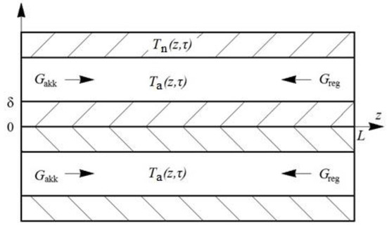
Figure 1.
Schematic of the SSRHE regenerative nozzle adjacent channels: δ is the channel wall thickness, Gakk and Greg is mass air flow at the heat accumulation and regeneration stages.
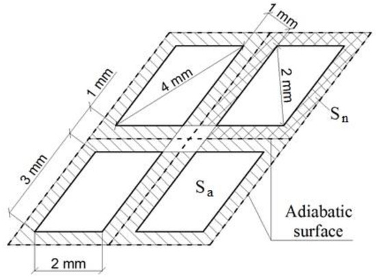
Figure 2.
Cross-section of the four adjacent nozzle channels: Sn and Sa are the nozzle and air passage cross-sectional areas.
In Equations (1) and (2), the density and specific mass heat capacity of the air and the nozzle material are assumed to be constant values, since the SSRHE operates in a temperature range of approximately −20 °C to 20 °C, within which these parameters vary slightly.
The energy balance does not consider the process of friction between the air flow and the inner surface of the channel due to its weak influence as a result of the low values of the flow velocity (w < 0.6 m/s) and air viscosity.
The heat transfer coefficient is calculated using the Nusselt number:
where is air thermal conductivity, W/(m⋅K) [15,16]; is the diameter of a single equivalent channel, m. Further,
where are constants depending on m = 1, 2, 3, …; Pe is the Péclet number.
The problem (1)–(2) with the given boundary conditions, (3) has been solved numerically using the finite difference method. The results of the solution can be found in [13].
It is known that SSRHEs are characterized by a laminar air flow regime in the nozzle channels [13]. When analyzing the results of the numerical solution of the model, it was revealed that the air temperature changes approximately linearly along the length of the channel, this corresponds to the conditions q = const (q is heat flow density on the channel wall). Therefore, the use of expression (5) to determine the Nusselt number is justified. It should be noted that, for the diameter of a single nozzle channel, d = 0.0016 m corresponding to the test sample, and the length of the initial thermal stabilization section is about 1/4 of the channel length, which, with a sufficient degree of accuracy, allows taking Nu ≈ 4.36.
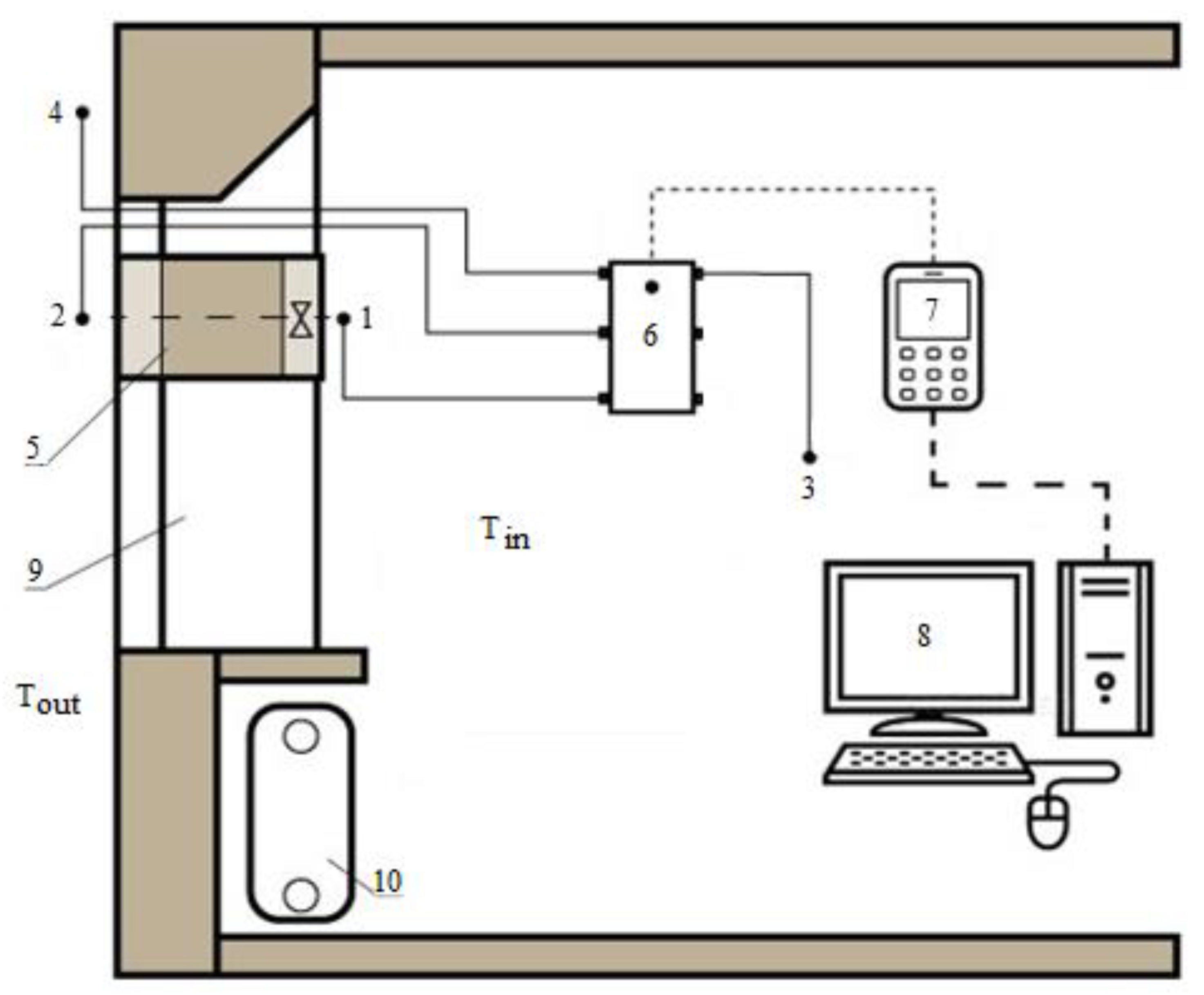
In order to validate the numerical solution results of the developed mathematical model, an experimental installation “SSRHE Temperature Conditions Research” has been created (Figure 3). An administrative facility with an area of 16.5 m2 and a volume of 99 m3 has been used as a climatic cell for the experiment.
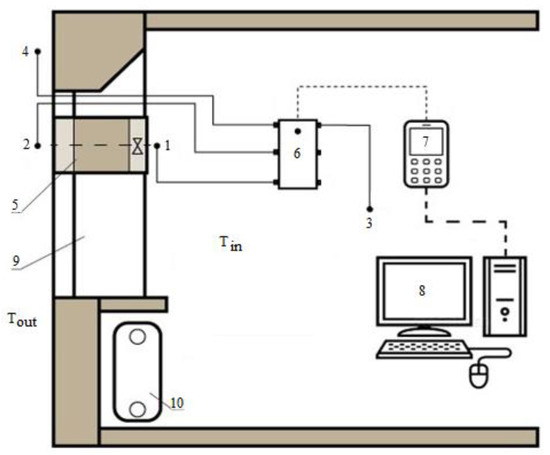
Figure 3.
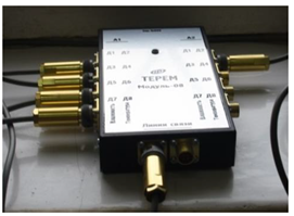
Schematic diagram of the experimental installation “SSRHE Temperature Conditions Research”: 1–4: air temperature sensors; 5: SSRHE; 6: sensor connection module; 7: temperature recorder; 8: personal computer; 9: window; 10: room heater.
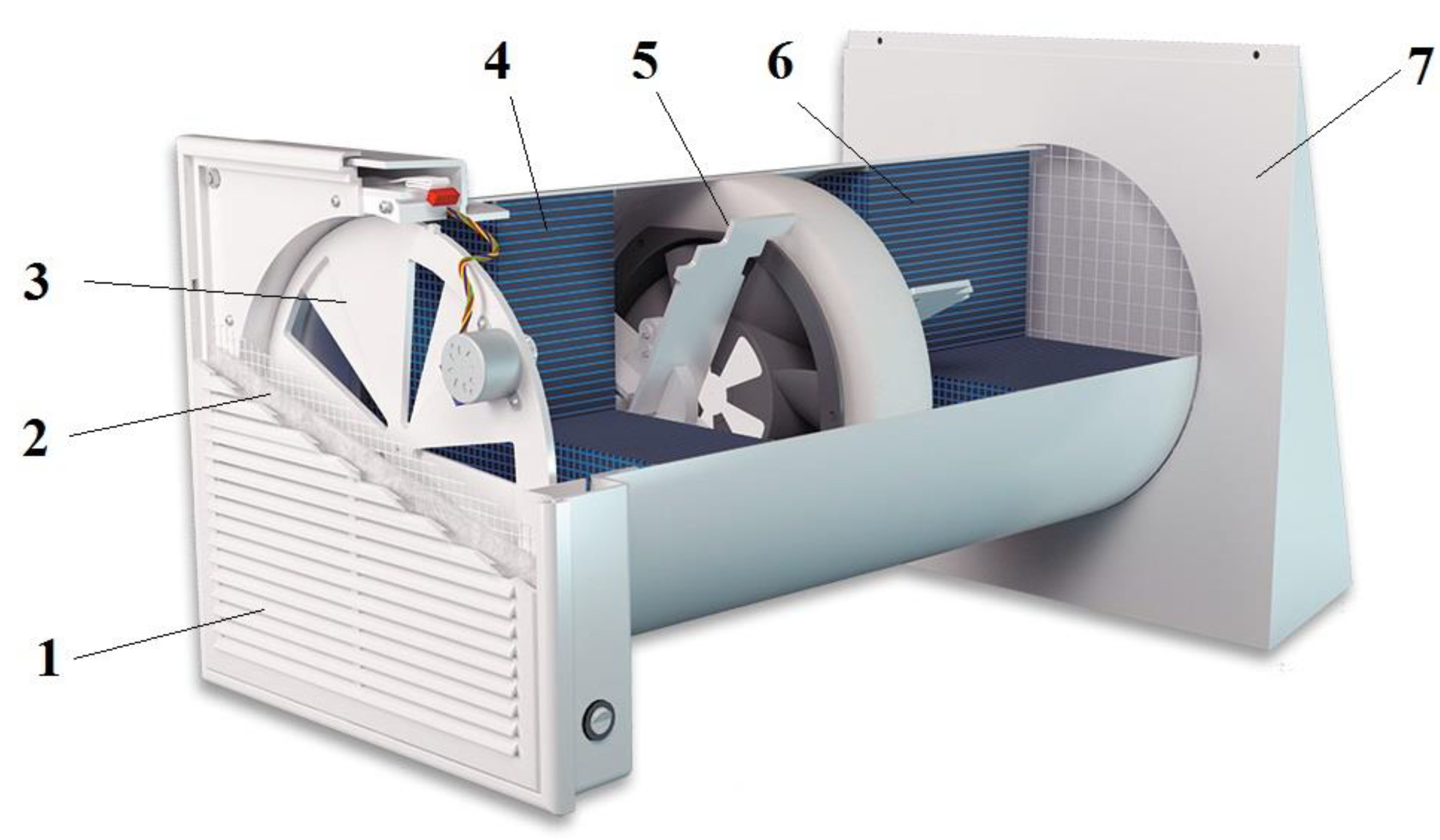
In general, the installation is an SSRHE mounted in the window construction, equipped with measuring instruments. The installation of the SSRHE in the window opening was caused by technical restrictions on drilling through holes in the exterior walls of this building. The UVRK-50 device, manufactured by SPF “Ecotherm” Omsk, was used as the SSRHE (Figure 4, Table 1). This device allows to measure the air temperature at the inner (Sensor 1) and outer (Sensor 2) ends of the SSRHE. There are also indoor (3) and outdoor air temperature sensors (4). All sensors are connected to the connection module (6), which, in turn, transmits a signal via the cable to the temperature recorder (7). The recorded data is transferred to a personal computer (8) for further analysis. A detailed description of the measuring instruments is given in Table 2.

Figure 4.
UVRC-50 device (ventilation compact recuperator with a maximum capacity of 50 m3/h) produced by SPF “Ecotherm”: 1: decorative grill; 2: G2-G3 filter; 3: automatic valve; 4: small regenerator; 5: reversible fan; 6: large regenerator; 7: outer hood.

Table 1.
Technical specifications of the UVRK-50 device reported by the manufacturer.
Table 2.
Measuring instruments description.
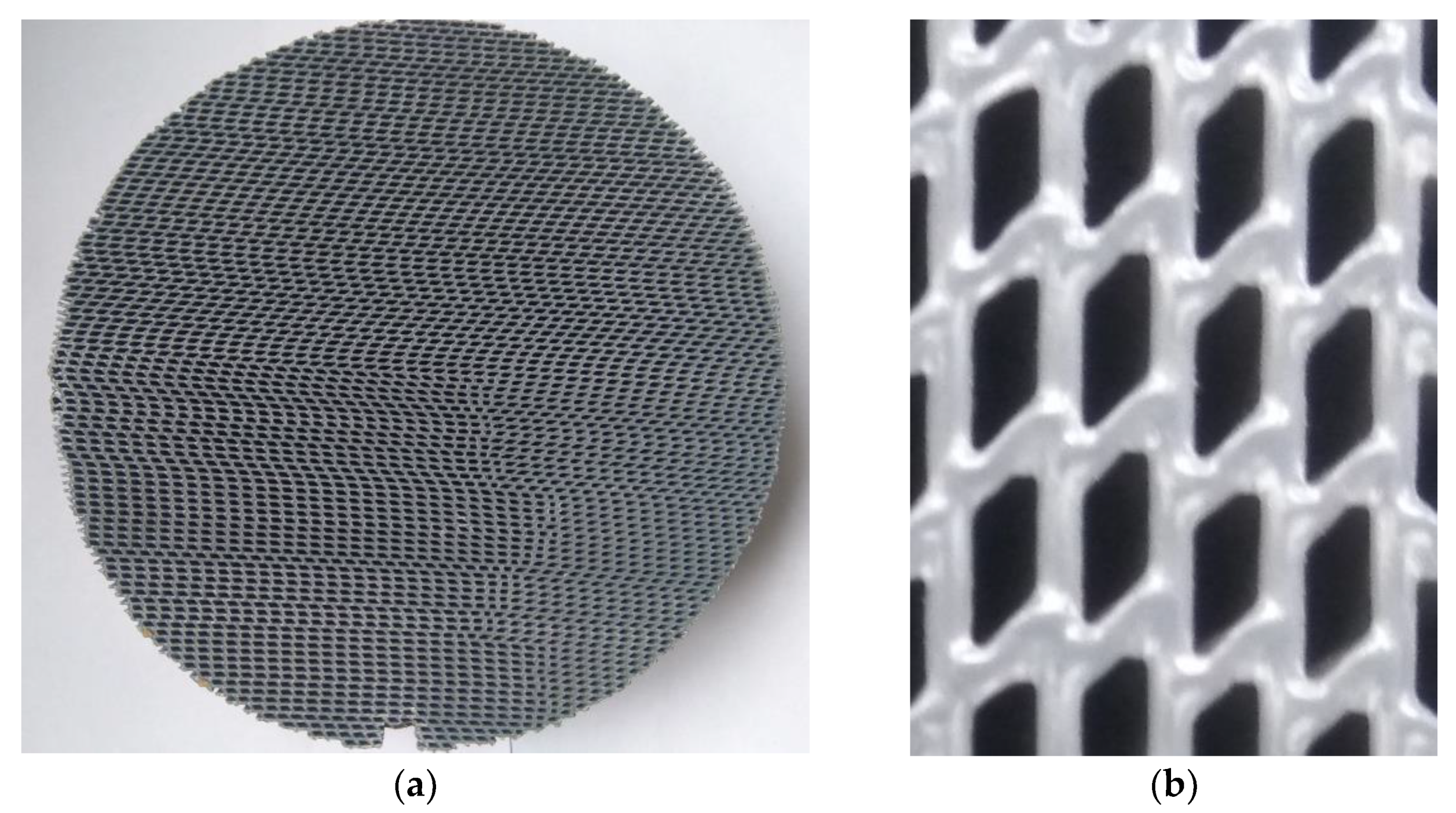
Figure 5 shows a cross-section of the nozzle with a scaled-up fragment. The figure clearly shows the diamond-shaped cross-section of the nozzle channels, based on which the physical model of the channel is made (Figure 2).
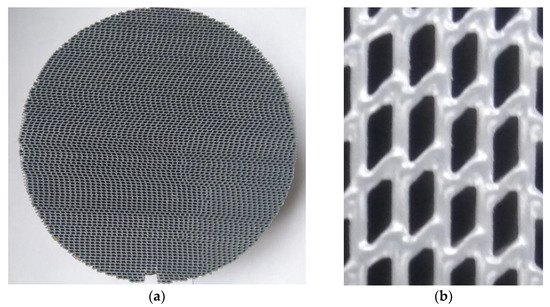
Figure 5.
Cross-section (the end) of the UVRK-50 nozzle (a) and a scaled-up image of the cross-section of several channels (b).
The calculated data deviation from the experimental date is determined as follows:
Here, is the air temperature at the inner () or outer () end of the SSRHE, obtained experimentally, °C; is the air temperature at the inner () or outer () end of the SSRHE, obtained by calculation, °C.
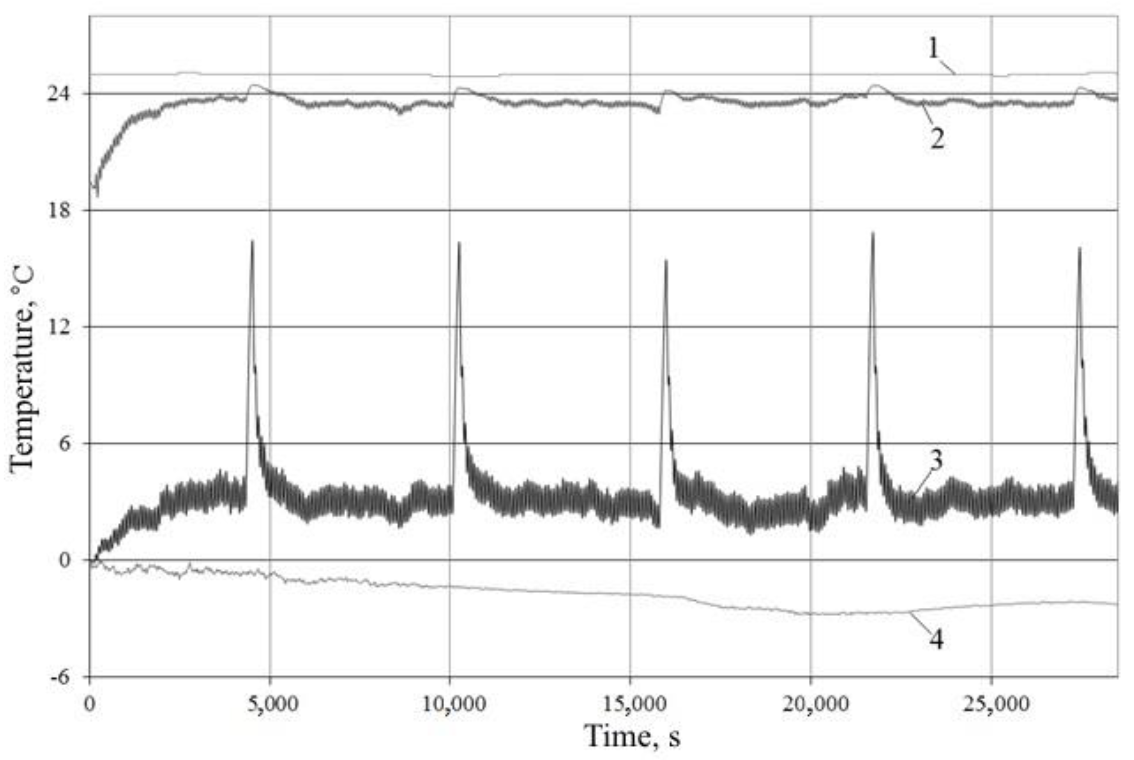
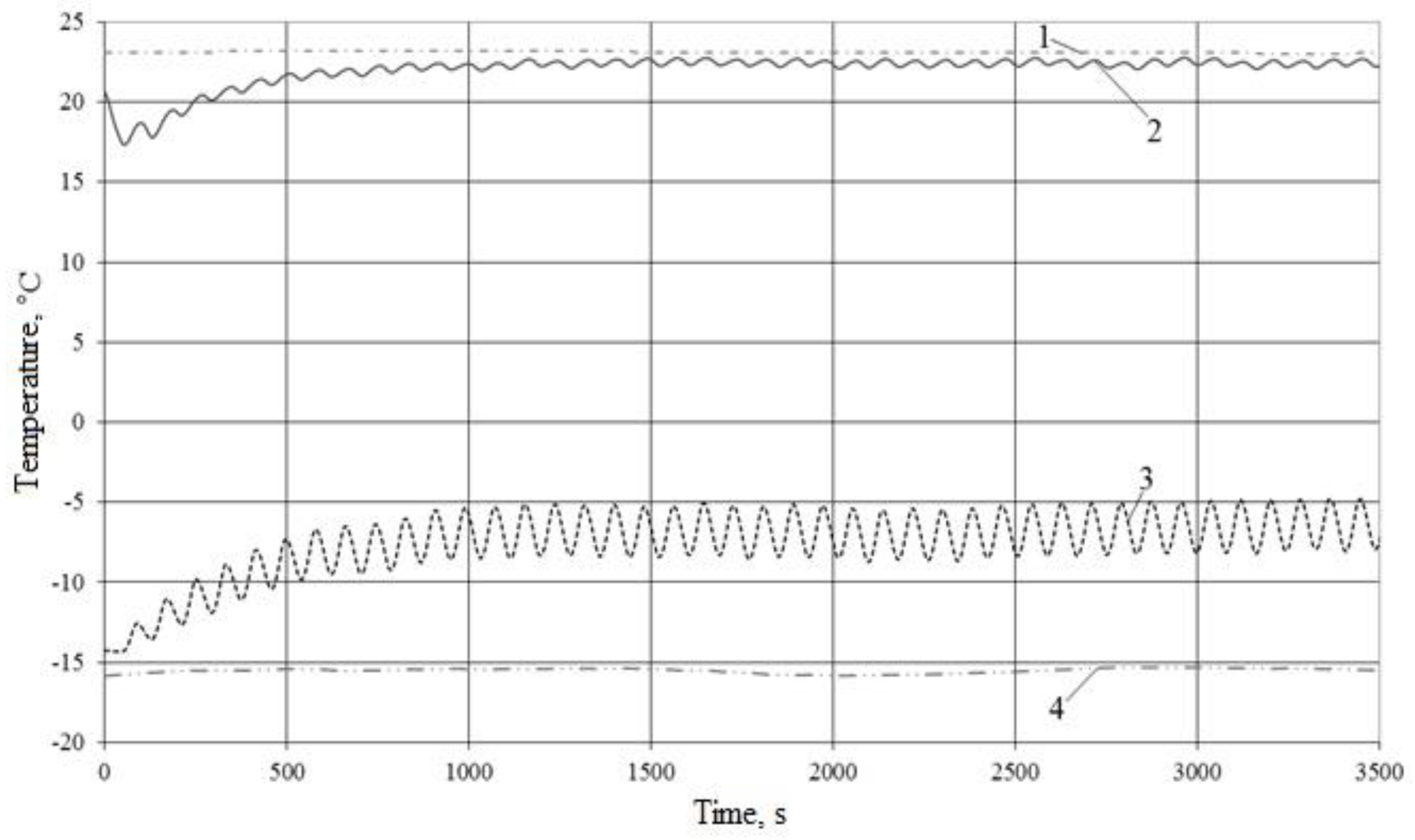
Figure 6 shows an example of the result of the air temperature measurements at the experimental installation. The experiment was carried out at the outdoor air temperature Tout = 0–−2.8 °C, the indoor air temperature Tin = 24.9–25.1 °C, and the air flow through the device L0 = 31 m3/h. The experiment duration was about 8 h. The figure shows the air temperature oscillatory conditions at the inner Ta1 and outer Ta2 ends of the SSRHE, characteristic of all the experiments. Moreover, one can see that, in the range from 0 to 4000 seconds, the temperature conditions stabilize and then fluctuate close to one axis. The high peaks in Graphs 2 and 3 characterize the nozzle blowdown with warm air programmed in the device to dry it from the forming condensate.

Figure 6.
Experiment results example with extended intervals (τ ≈ 8 h): 1—Tin, 2—Ta1, 3—Ta2, 4—Tout.
Figure 7 shows an example of an experiment result with a time of τ ≈ 1 h with Tout = −15.3–−15.8 °C, Tin = 23.0–23.2 °C, L0 = 31 m3/h. The graphs also show the process of temperature stabilization. Individual fluctuations are more clearly seen. All the experiments had the following characteristic feature: the maxima of the function Ta1 and the minima of the function Ta2 did not reach the indoor and outdoor temperatures, respectively. This can be explained by the fact that, during operation, a temperature gradient forms near the temperature sensor due to the considerable air thermal lag and does not sufficiently achieve high air assimilation. The air thermal lag results from its low thermal conductivity and specific heat capacity. Low assimilation (dissolution) of supply air in the indoor air when flowing in (regeneration stage) and indoor air assimilation in the outdoor air when flowing out (accumulation stage) occur due to a short inflow/exhaust process which forms an unstable flow that spreads weakly in the environment. In addition, the rapid change of the inflow and exhaust cycles contributes to the release of some supply air back into the outdoor environment and the return of some exhaust air back indoors. That is, with a sufficiently rapid change of the SSRHE stages (less than 1 min), the air around the sensor does not reach the temperature of the indoor or outdoor environment due to the insufficiently active processes of thermal conductivity and convection between warm and cold air flows.
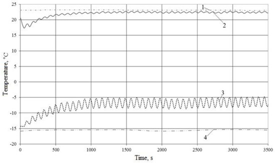
Figure 7.
Experiment results example with short intervals (τ ≈ 1 h): 1: Tin; 2: Ta1; 3: Ta2; 4: Tout.
3. Results
In order to verify the mathematical model, we compared the experimental data on the change in air temperature at the ends of the SSRHE with the calculated data and determined the percentage deviation.
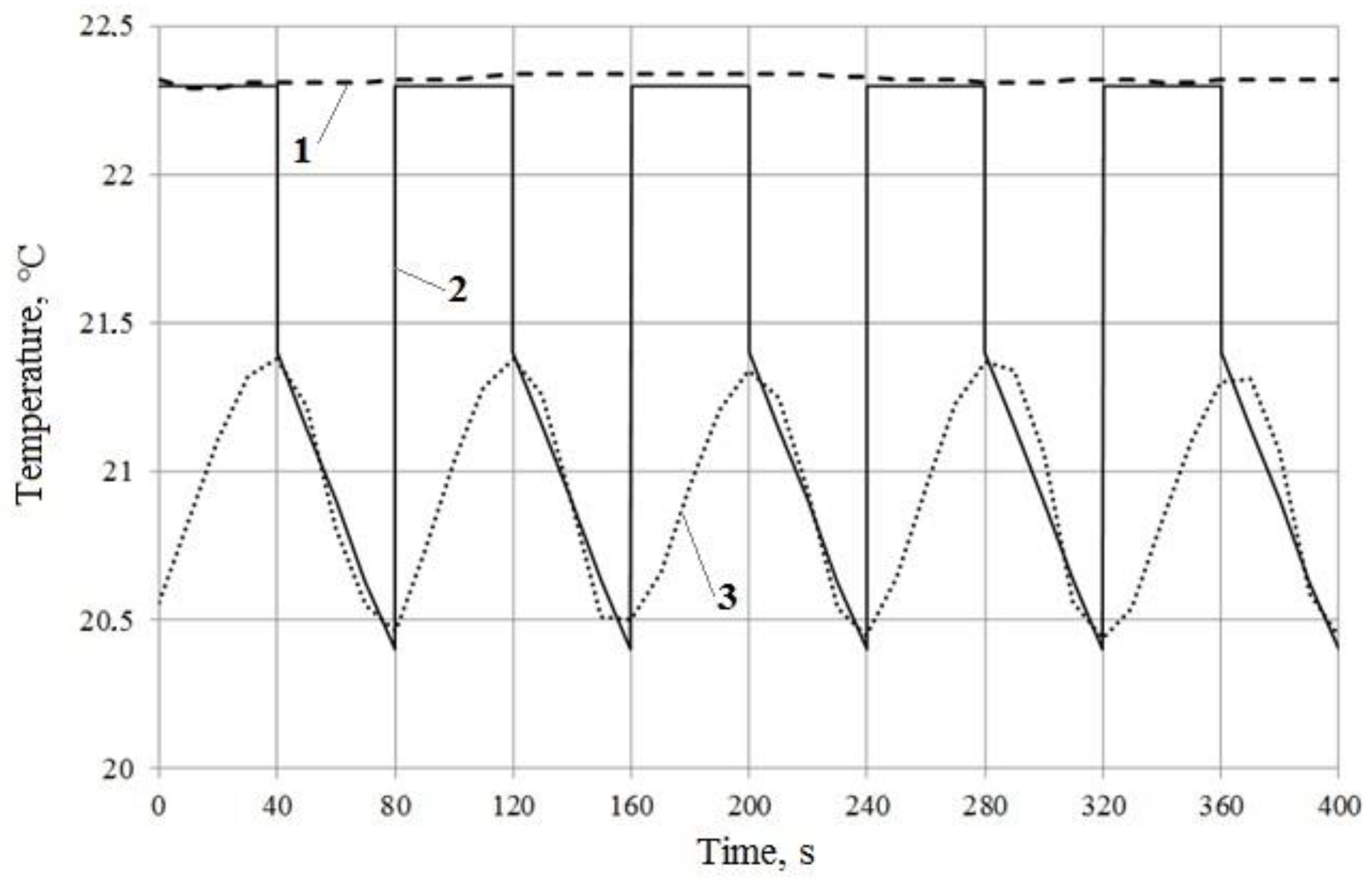
Figure 8 and Figure 9 show a comparison of calculated and experimental data on changes in air temperature over time at the inner and outer ends of the SSRHE, respectively.
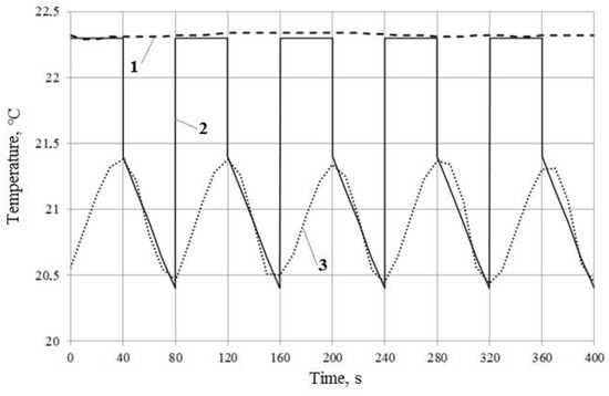
Figure 8.
Comparison of experimental and calculated data on the change in air temperature at the inner end of the SSRHE: 1—Tin, 2—calculation, 3—experiment.
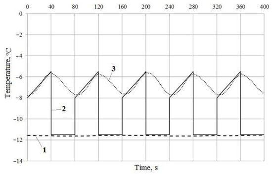
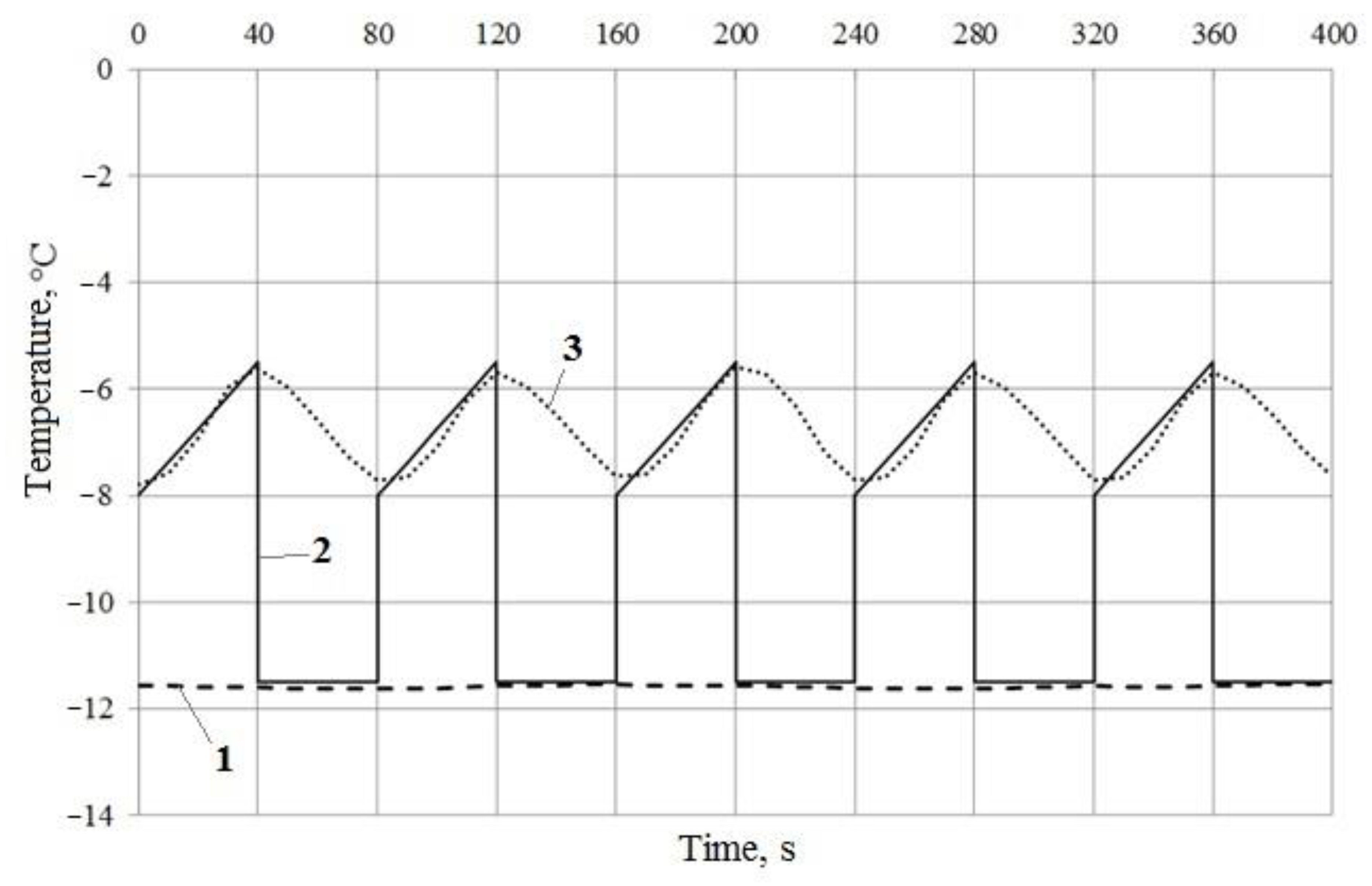
Figure 9.
Comparison of experimental and calculated data on the change in air temperature at the outer end of the SSRHE: 1—Tout, 2—calculation, 3—experiment.
The initial conditions of the experiment and the calculation were as follows:
- -
- Outdoor temperature Tout = −11.6 °C;
- -
- Indoor temperature Tin = 22.3 °C;
- -
- Total volumetric air flow L0 = 31 m3/h = 8.61·10−3 m3/s;
- -
- Total mass air flow G0 = 9.24·10−3 kg/s;
- -
- Air flow through a single channel G = 2.65·10−6 kg/s;
- -
- Thermal energy accumulation/regeneration stage time τakk = τreg = 40 s;
- -
- Channel length l = 0.15 m;
- -
- Equivalent diameter d = 0.0016 m;
- -
- Density of the nozzle material pn = 1400 kg/m3;
- -
- Specific mass heat capacity of the nozzle material cn = 2000 J/kg·K;
- -
- Specific mass heat capacity of air ca = 1005 J/kg·K;
- -
- Atmospheric pressure p = 9.81·104 Pa.
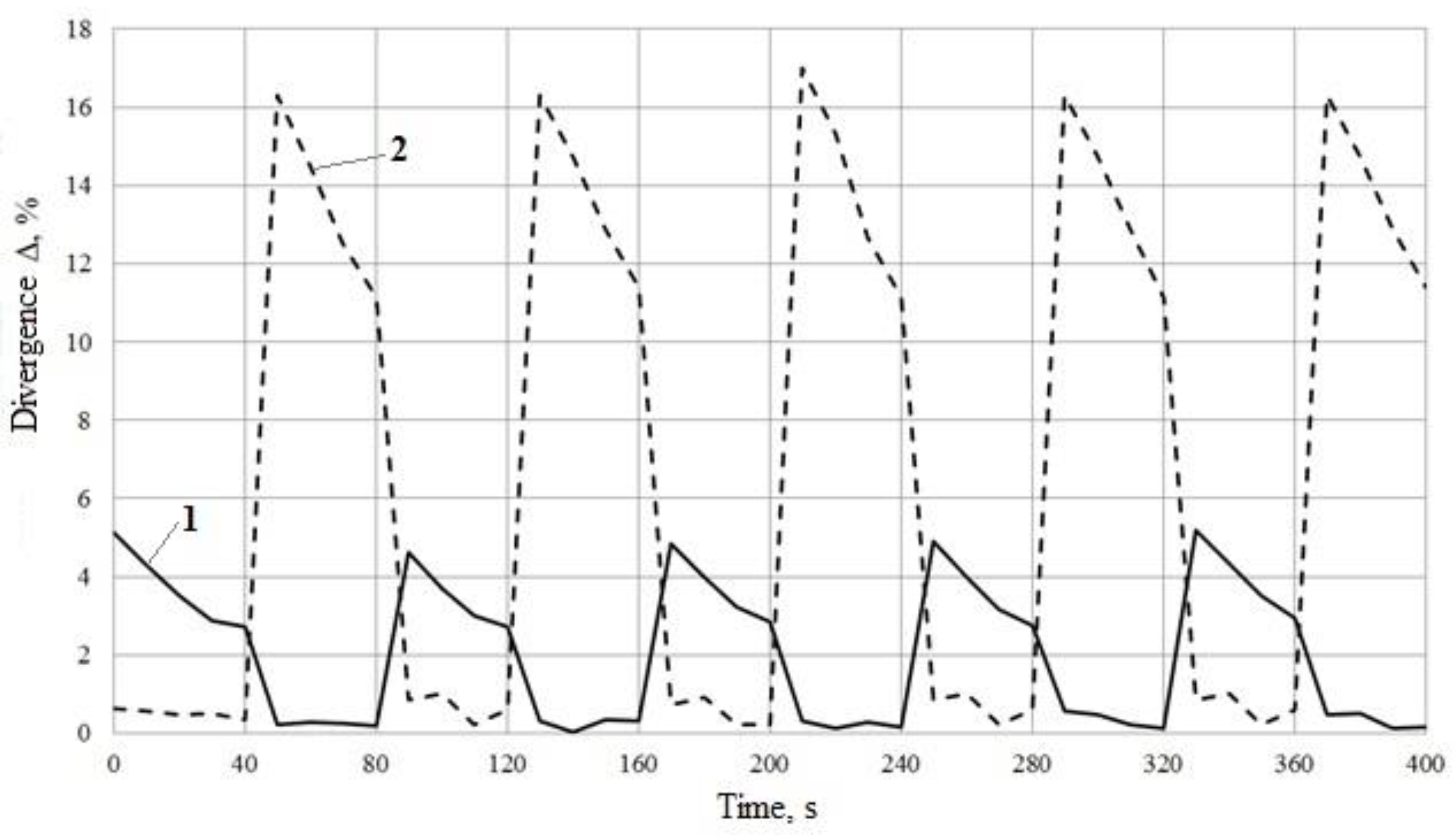
The deviations are shown in Figure 10.
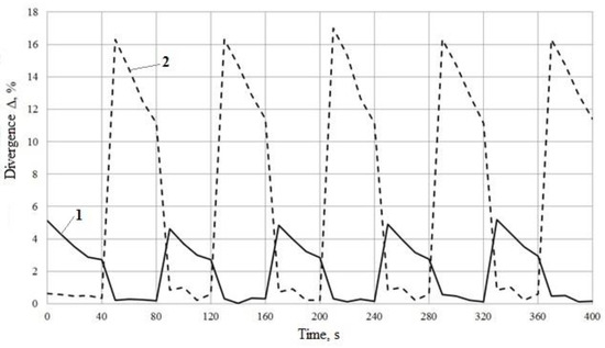
Figure 10.
Percentage deviation of the calculated data from the experimental data on the change in air temperature at the ends of the SSRHE: 1: inner end; 2: outer end.
Finally, the following results were obtained:
1. At the inner end of the SSRHE, according to the stages of thermal energy regeneration, the deviation of the calculated and experimental data of air temperature does not exceed 0.2% (Figure 8 and Figure 10). At the outer end of the SSRHE, by stages of accumulation, the deviation does not exceed 0.5% (Figure 9 and Figure 10).
4. Discussion
The high repeatability of the calculated and experimental air temperature values at the inner end at the regeneration stages and at the outer end at the accumulation stages allows for the assertion that the proposed mathematical model is adequate and can be used for further studies, including those for determining the SSRHE rational parameters.
The considerable deviation of the temperature values at the inner end at accumulation stages and at the outer end at the regeneration ones is explained by the following: The abrupt change of the calculated temperature to the constant value Tin or Tout happens due to the fact that the mathematical model in its implementation allows to change the SSRHE stages instantly. In real practice, the temperature sensor has a certain thermal lag, and it is also influenced by the processes described in the explanation to Figure 7, which results in recording a smooth change in the air temperature. Besides, in the mathematical model, the boundary conditions imply that the air temperature at the SSRHE’s ends becomes constant and is equal to the temperature of the medium which the air comes from. Despite the fact that the model includes thermal inertia, instantaneous switching between stages occurs due to the fact that, at the ends of the SSRHE, the boundary conditions set the equality of the required air temperature to the temperature of the indoor or outdoor environment. Therefore, at the inner end, at the stages of accumulation, the air temperature instantly acquires a constant value of the internal environment from where the air enters the channel, and, vice versa at the outer end at the stages of regeneration, the air temperature instantly acquires a constant value of the external environment. Thus, the comparison between the calculated and experimental air temperature values for these stages can be considered incorrect.
To solve the problem of the high deviation of the calculated air temperature values from the experimental values at these stages, it is necessary to perform an experiment with the installation of a temperature sensor inside the nozzle channel. However, this is quite difficult to do due to the small size of the diameter of the channel.
5. Conclusions
The article has experimentally verified and confirmed the adequacy of the proposed mathematical model of heat exchange between air and the nozzle in the SSRHE, in which the thermal conductivity of the nozzle along the channel is neglected. This model can be used to determine the parameters of the SSRHE in their calculation and design.
Author Contributions
Conceptualization, N.M.; methodology, N.M.; software, N.M.; validation, N.M. and T.M.; formal analysis, N.M.; investigation, N.M.; resources, N.M.; data curation, N.M.; writing—original draft preparation, N.M.; writing—review and editing, T.M.; visualization, N.M.; supervision, T.M.; project administration, N.M.; funding acquisition, N.M. All authors have read and agreed to the published version of the manuscript.
Funding
This research received no external funding.
Conflicts of Interest
The authors declare no conflict of interest.
References
- Roulet, C.-A.; Heidt, F.; Foradini, F.; Pibiri, M.-C. Real heat recovery with air handling units. Energy Build. 2001, 33, 495–502. [Google Scholar] [CrossRef]
- Haniff, M.F.; Selamat, H.; Yusof, R.; Buyamin, S.; Ismail, F.S. Review of HVAC scheduling techniques for buildings towards energy-efficient and cost-effective operations. Renew. Sustain. Energy Rev. 2013, 27, 94–103. [Google Scholar] [CrossRef]
- Fakhrabadi, F.; Kowsary, F. Optimal design of a regenerative heat and mass exchanger for indirect evaporative cooling. Appl. Therm. Eng. 2016, 102, 1384–1394. [Google Scholar] [CrossRef]
- Sinitsyn, A.A.; Monarkin, N.N.; Rogulina, T.V. Federal law of power saving and opportunity of developing new the switching heat recovery devices for heat supply needs. World Appl. Sci. J. 2013, 27, 361–365. [Google Scholar] [CrossRef]
- Penev, A.; Tsokov, L. Application of polymer thermal store material in fixed honeycomb regenerative heat exchanger. In Proceedings of the E3S Web of Conferences, Sozopol, Bulgaria, 19–21 September 2020; p. 01001. [Google Scholar] [CrossRef]
- Aktershev, S.P. The regenerative heat exchanger with periodic veering of the flow. In Proceedings of the XXXV Siberian Thermophysical Seminar, STS 2019, Novosibirsk, The Soviet Union, 27–29 August 2019; Institute of Physics Publishing: Novosibirsk, Russia, 2019; p. 012125. [Google Scholar]
- Monarkin, N.; Sinitsyn, A.; Pavlov, M.; Akhmetov, T. The influence of main parameters of regenerative heat exchanger on its energy efficiency. In Proceedings of the E3s Web of Conferences, Prague, Czech Republic, 14–15 May 2020; EDP Sciences: Prague, Czech Republic, 2020; p. 01024. [Google Scholar] [CrossRef]
- Monarkin, N.; Sinitsyn, A.; Karpov, D.; Akhmetov, T. Method for designing energy-efficient ventilation systems based on regenerative heat exchangers. In Proceedings of the E3s Web of Conferences, Prague, Czech Republic, 14–15 May 2020; EDP Sciences: Prague, Czech Republic, 2020; p. 01037. [Google Scholar] [CrossRef]
- Solovyev, S.A. A probabilistic approach to estimation of the ultimate load of end-bearing piles on settlement criterion. Mag. Civ. Eng. 2020, 96, 70–78. [Google Scholar] [CrossRef]
- Solovyeva, A.; Solovyev, S. Reliability analysis of rhs steel trusses joints based on the p-boxes approach. Int. J. Comput. Civ. Struct. Eng. 2021, 17, 87–97. [Google Scholar] [CrossRef]
- Nizovtsev, M.I.; Borodulin, V.Y.; Letushko, V.N. Regenerative heat exchanger with a periodic change in the airflow direction for room ventilation. Thermophys. Aeromechanics 2015, 22, 755–765. [Google Scholar] [CrossRef]
- Skrzycki, M.; Jedlikowski, A.; Anisimov, S. Efficiency of heat recovery of storage matrix regenerative heat exchanger. In Proceedings of the Indoor Air Quality and Environment, the XVII International Scientific Conference, Moscow, Russia, 11–18 September 2019; Gvozdkov, A.N., Ed.; Volgograd State Medical University: Moscow, Russia, 2019; pp. 159–165. [Google Scholar]
- Monarkin, N.N.; Lukin, S.V.; Kochkin, A.A. Mathematical model of heat transfer in a thin-walled regenerator. Privolzhskii Nauchnyi Zhurnal. 2018, 3, 57–62. [Google Scholar]
- Monarkin, N.; Lukin, S.; Anurov, Y.M.; A Tihomirov, B.; A Agasiants, G.; Galileev, S.M.; Akhmetov, T.R. Thermal and aerodynamic efficiency of a stationary switching regenerative heat exchanger. In IOP Conference Series: Earth and Environmental Science, Proceedings of the International Scientific Conference on Efficient Waste Treatment 2018, EWT 2018, St. Petersburg, Russia, 13–14 December 2018; Institute of Physics Publishing: Petersburg, Russia, 2019; p. 012067. [Google Scholar] [CrossRef]
- Karpov, D. The active method of control the thermal conductivity of building materials and products. Bull. Belgorod State Technol. Univ. Named V. G. Shukhov 2019, 4, 57–62. [Google Scholar] [CrossRef]
- Karpov, D.; Agafonov, V.; Pisarenko, V.; Berezin, P.; Derevianko, O.; Makoev, S.; Egororov, M. Determination of thermal diffusivity for rigid body at non-stationary thermal conditions. In IOP Conference Series: Earth and Environmental Science, Proceedings of the Collection of materials International Scientific and Practical Conference, Kazan, Russia, 29 October–2 November 2018; Institute of Physics and IOP Publishing Limited: Kazan, Russia, 2019; p. 012097. [Google Scholar] [CrossRef]


Publisher’s Note: MDPI stays neutral with regard to jurisdictional claims in published maps and institutional affiliations. |
© 2022 by the authors. Licensee MDPI, Basel, Switzerland. This article is an open access article distributed under the terms and conditions of the Creative Commons Attribution (CC BY) license (https://creativecommons.org/licenses/by/4.0/).