
Improving the Frequency Response of Hybrid Microgrid under Renewable Sources’ Uncertainties Using a Robust LFC-Based African Vulture Optimization Algorithm


 ,
,  ,
,  and
and 
Abstract
:1. Introduction
- Design and simulation of a robust cascaded controller called (1+PD)-PID in order to regulate the system response in terms of frequency and tie-line power deviations;
- Using a novel AVOA optimization algorithm to find the optimal controller parameters to ensure an optimal behavior of the controller;
- Testing the effectiveness and validation of the (1+PD)-PID controller by subjecting the microgrid to various types of fluctuations and uncertainties such as distinct step load disturbances, variable load variations, and RES fluctuations;
- Verifying the superiority of the (1+PD)-PID controller by comparing its performance against that of other controllers such as the conventional PID controller, FOPID controller and TID controller.
2. Structure of The Two-Area Hybrid Power System
- Non-reheat Thermal System:
- Power System:
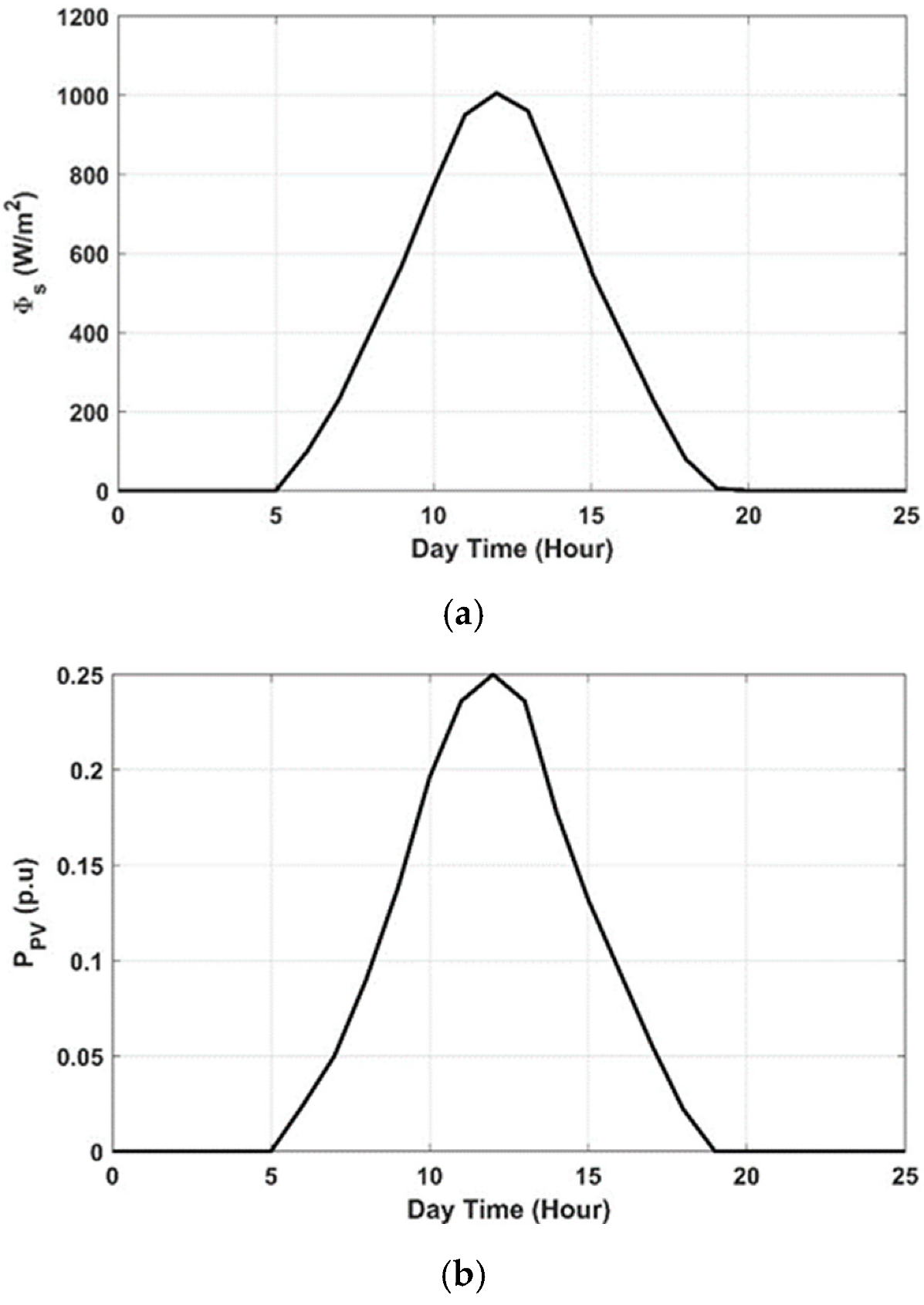
- PV System:
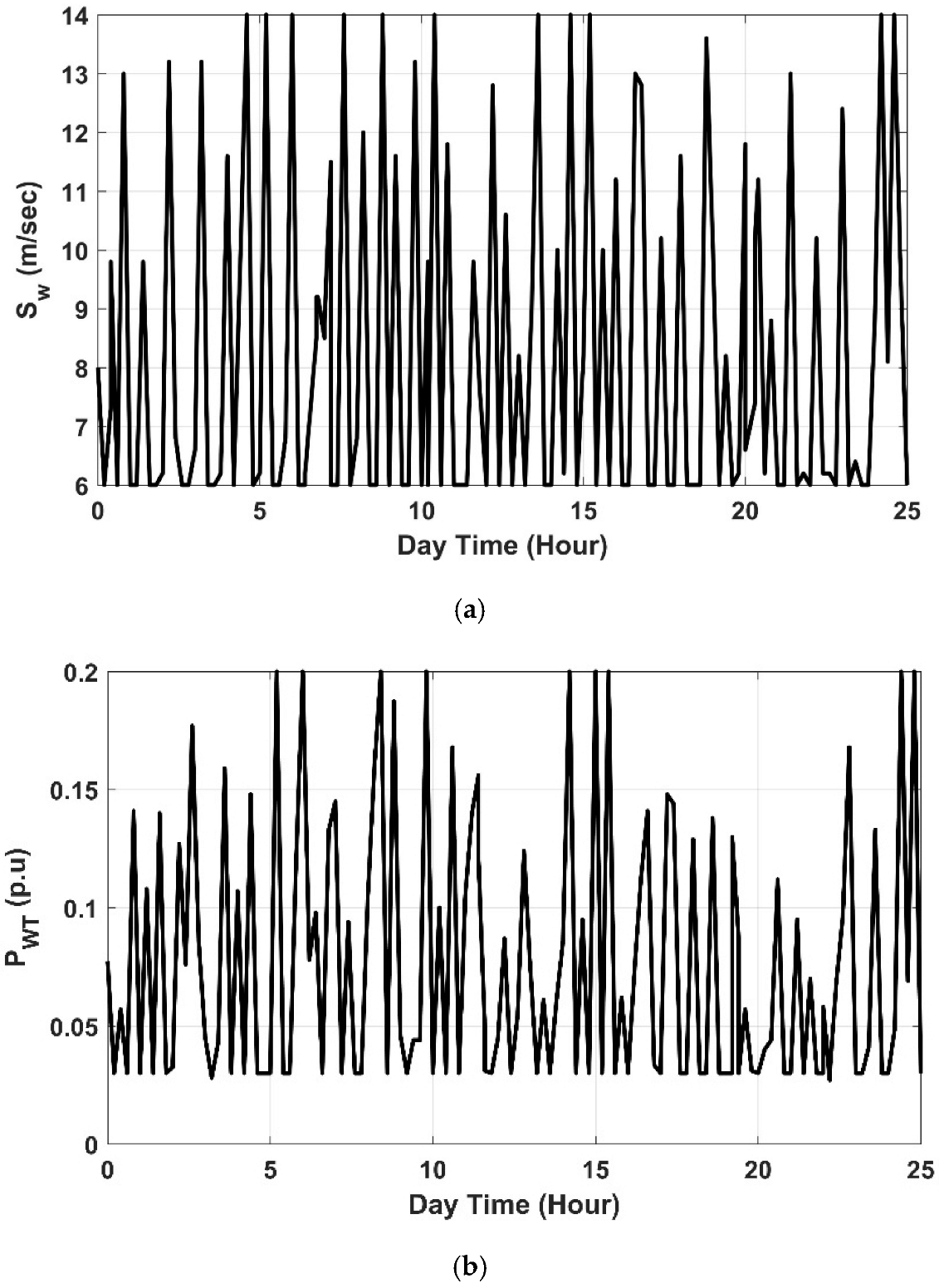
- Wind Turbine Generator (WTG):
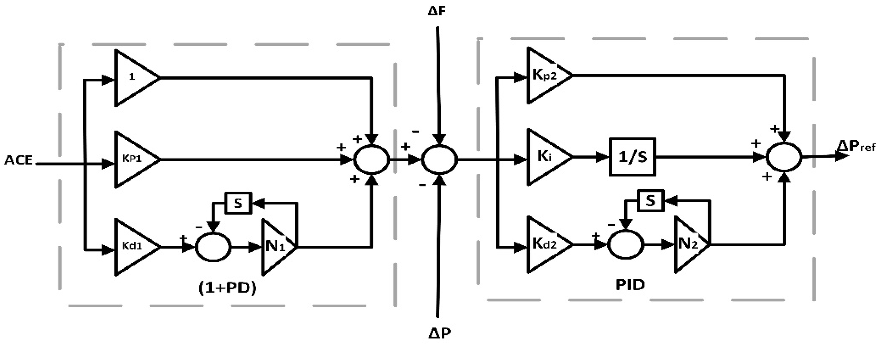
3. Structure of the (1+PD)-PID Cascaded Controller
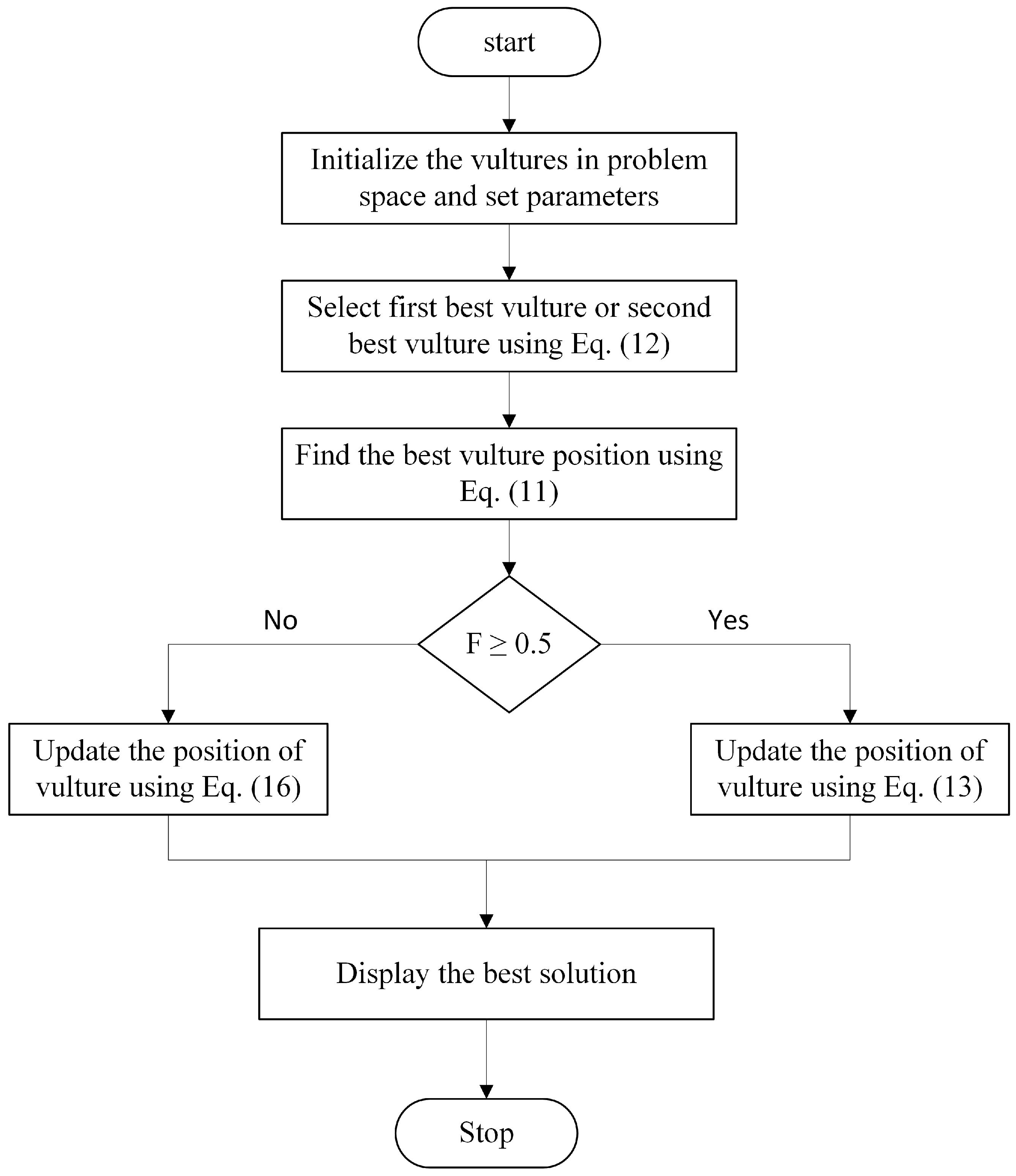
4. African Vulture Optimization Algorithm (AVOA)
4.1. Exploration Phase
4.2. Exploitation Phase
- Determine the iterations maximum number and the size of the population;
- Compute the vulture fitness value;
- Select using Equation (12) for all vultures;
- Use Equation (11) to compute the position of the best vulture;
- Depending on the vulture satiation rate, use Equation (13) or Equation (16) to update the position of the vulture;
- Save the position of the optimal vulture then compute the value of the fitness function as long as the iteration maximum number is not reached.
5. Results and Discussions
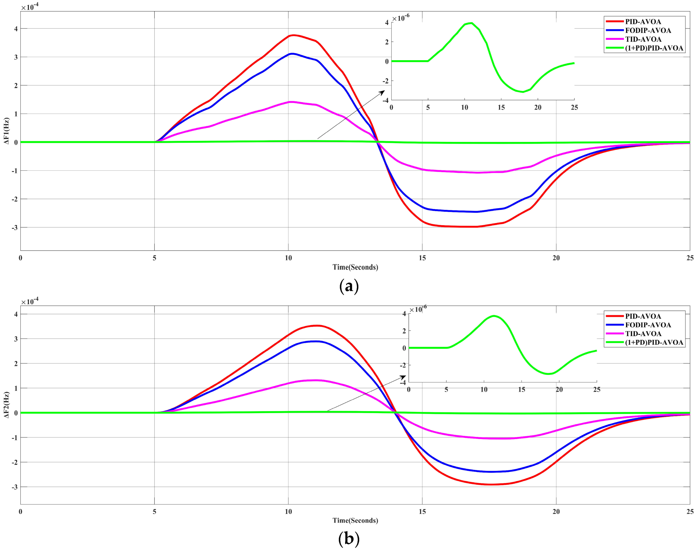
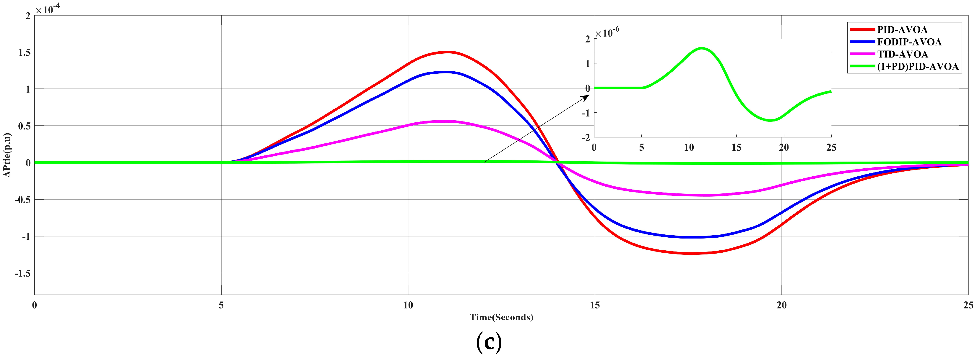
5.1. Scenario 1: System Performance under 10% SLP in Area-1
5.1.1. Comparison of AVOA Performance with Other Optimization Algorithms
5.1.2. Applying the Proposed AVOA Algorithm to Different Controllers
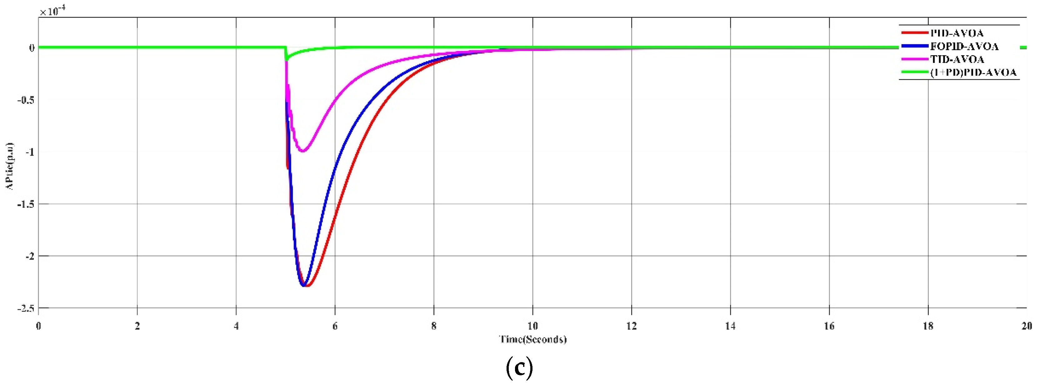
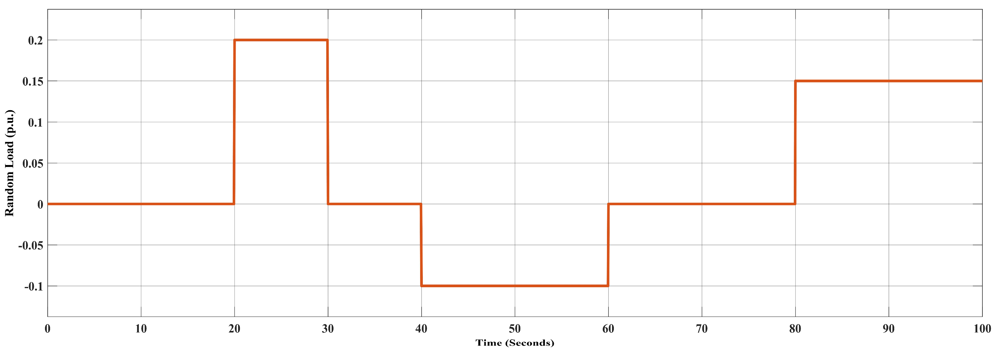
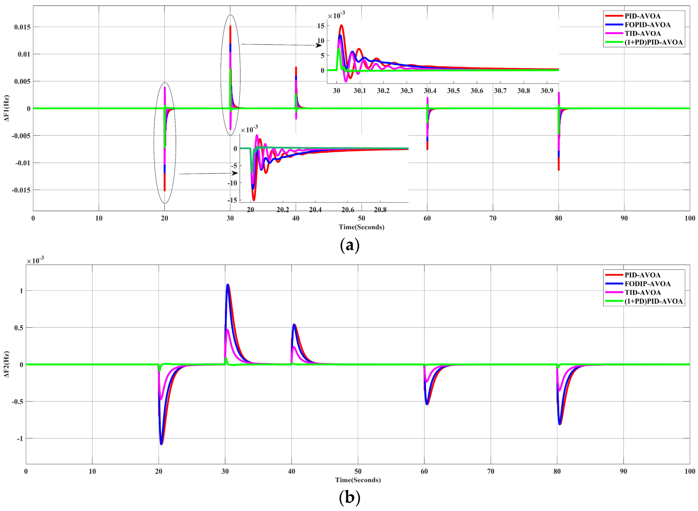
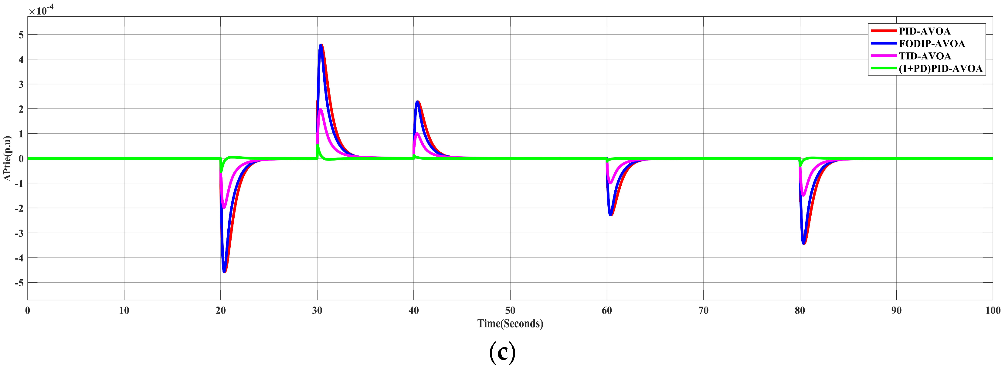
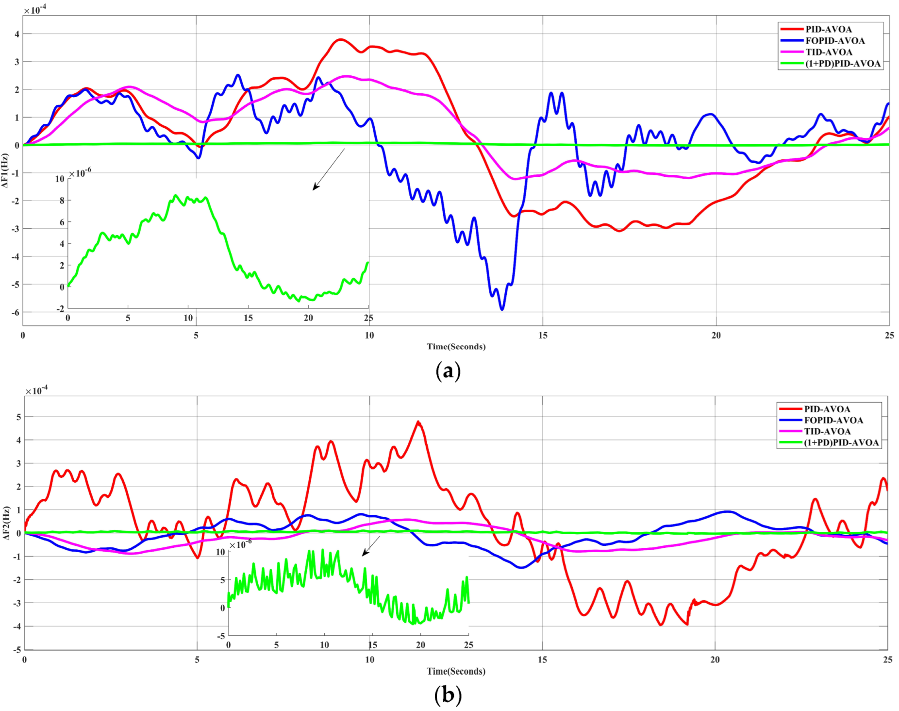
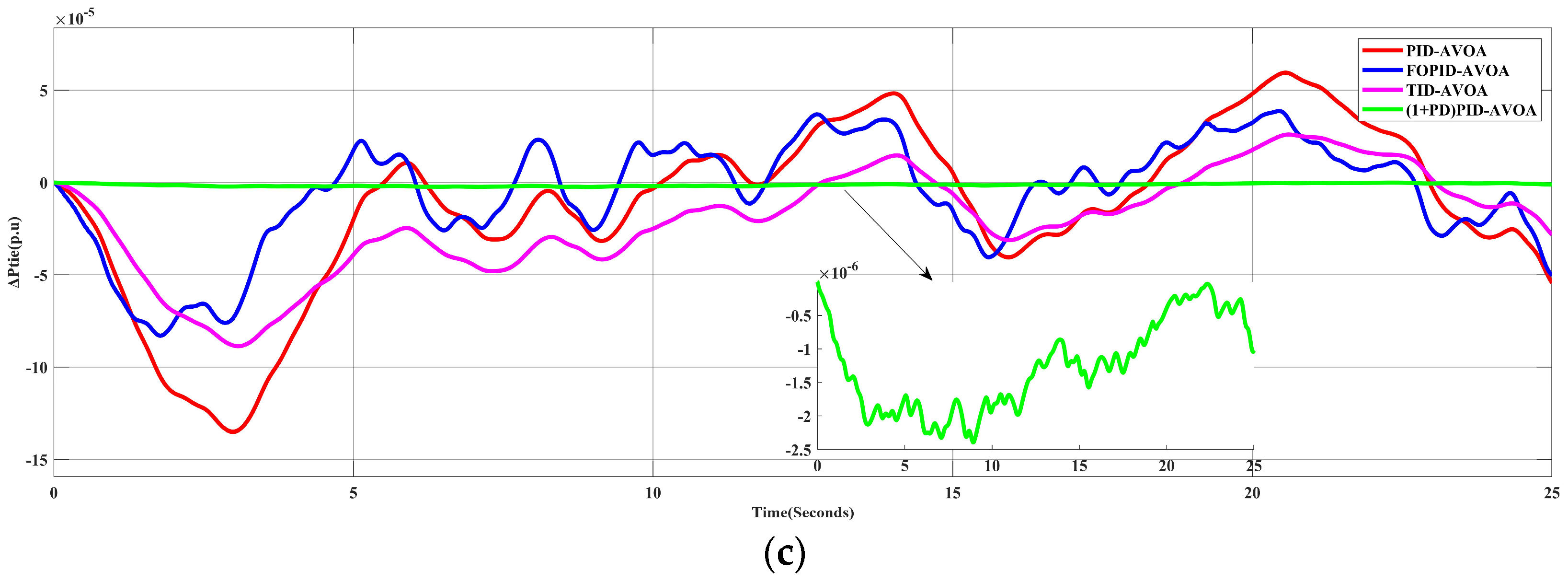
5.2. Scenario 2: The System Performance for Random Load Profile
5.3. Scenario 3: The Effect of Installing Solar PV Unit in Area-1
5.4. Scenario 4: The Effect of Installing a Wind Farm Unit in Area-2
5.5. Scenario 5: The Effect of Inserting RES into the System
6. Results and Discussions
Author Contributions
Funding
Institutional Review Board Statement
Informed Consent Statement
Data Availability Statement
Conflicts of Interest
References
- Abumeteir, H.A.; Vural, A.M. Design and Optimization of Fractional Order PID Controller to Enhance Energy Storage System Contribution for Damping Low-Frequency Oscillation in Power Systems Integrated with High Penetration of Renew-able Sources. Sustainability 2022, 14, 5095. [Google Scholar] [CrossRef]
- Singh, K.; Amir, M.; Ahmad, F.; Khan, M.A. An Integral Tilt Derivative Control Strategy for Frequency Control in Multimicrogrid System. IEEE Syst. J. 2021, 15, 1477–1488. [Google Scholar] [CrossRef]
- Singh, C.; Padhy, P.K. Fractional Order Controller Design for interconnected Power System using BAT optimization Al-gorithm. In Proceedings of the 2022 Second International Conference on Artificial Intelligence and Smart Energy (ICAIS), Coimbatore, India, 23–25 February 2022; pp. 1634–1639. [Google Scholar]
- Mohanty, P.; Sahu, R.K. Analysis of Hybrid Tilt Integral Derivative Controller for Multi area Power System with Real Time Simulation. In Proceedings of the 2020 International Conference on Computational Intelligence for Smart Power System and Sustainable Energy (CISPSSE), Keonjhar, Odisha, India, 29–31 July 2020. [Google Scholar]
- Rerkpreedapong, D.; Hasanovic, A.; Feliachi, A. Robust load frequency control using genetic algorithms and linear matrix inequalities. IEEE Trans. Power Syst. 2003, 18, 855–861. [Google Scholar] [CrossRef]
- Kaliannan, J.; Baskaran, A.; Dey, N.; Ashour, A.S. Ant colony optimization algorithm based PID controller for LFC of single area power system with non-linearity and boiler dynamics. World J. Model. Simul. 2016, 12, 3–14. [Google Scholar]
- Ali, E.; Abd-Elazim, S. Bacteria foraging optimization algorithm based load frequency controller for interconnected power system. Int. J. Electr. Power Energy Syst. 2011, 33, 633–638. [Google Scholar] [CrossRef]
- Mohanty, B.; Panda, S.; Hota, P. Controller parameters tuning of differential evolution algorithm and its application to load frequency control of multi-source power system. Int. J. Electr. Power Energy Syst. 2014, 54, 77–85. [Google Scholar] [CrossRef]
- Singh, K.; Shankar, G. PID parameters tuning using modified particle swarm optimization and its application in load frequency control. In Proceedings of the 2016 IEEE 6th International Conference on Power Systems (ICPS), New Delhi, India, 4–6 March 2016; pp. 1–6. [Google Scholar] [CrossRef]
- Maqbool, H.; Yousaf, A.; Asif, R.M.; Rehman, A.U.; Eldin, E.T.; Shafiq, M.; Hamam, H. An Optimized Fuzzy Based Control Solution for Frequency Oscillation Reduction in Electric Grids. Energies 2022, 15, 6981. [Google Scholar] [CrossRef]
- Ramlal, T.; Elgammal, A. Optimal Frequency Control Management of Grid Integration PV/Wind/FC/Storage Battery Based Smart Grid Using Multi Objective Particle Swarm Optimization MOPSO and Model Predictive Control (MPC). Eur. J. Eng. Technol. Res. 2021, 6, 50–56. [Google Scholar]
- Roshin, K.R.; Bindumol, E.K. Firefly Algorithm Based Tuning of Integral Controller for Frequency Regulation of Hybrid Two Area Power System with Nonlinearities and Electric Vehicles. In Proceedings of the 2020 International Conference on Power Electronics and Renewable Energy Applications (PEREA), Kannur, India, 27–28 November 2020; pp. 1–6. [Google Scholar] [CrossRef]
- Ali, M.; Kotb, H.; Aboras, K.M.; Abbasy, N.H. Design of Cascaded PI-Fractional Order PID Controller for Improving the Frequency Response of Hybrid Mi-crogrid System Using Gorilla Troops Optimizer. IEEE Access 2021, 9, 150715–150732. [Google Scholar] [CrossRef]
- Celik, E.; Öztürk, N.; Arya, Y.; Ocak, C. (1 + PD)-PID cascade controller design for performance betterment of load frequency control in diverse electric power systems. Neural Comput. Appl. 2021, 33, 15433–15456. [Google Scholar] [CrossRef]
- Fathy, A.; Alharbi, A.G. Recent Approach Based Movable Damped Wave Algorithm for Designing Fractional-Order PID Load Frequency Control Installed in Multi-Interconnected Plants With Renewable Energy. IEEE Access 2021, 9, 71072–71089. [Google Scholar] [CrossRef]
- Ahmed, E.M.; Mohamed, E.A.; Elmelegi, A.; Aly, M.; Elbaksawi, O. Optimum Modified Fractional Order Controller for Future Electric Vehicles and Renewable Energy-Based Interconnected Power Systems. IEEE Access 2021, 9, 29993–30010. [Google Scholar] [CrossRef]
- Ahmed, E.M.; Elmelegi, A.; Shawky, A.; Aly, M.; Alhosaini, W.; Mohamed, E.A. Frequency Regulation of Electric Vehicle-Penetrated Power System Using MPA-Tuned New Combined Fractional Order Controllers. IEEE Access 2021, 9, 107548–107565. [Google Scholar] [CrossRef]
- Mohamed, E.A.; Ahmed, E.M.; Elmelegi, A.; Aly, M.; Elbaksawi, O.; Mohamed, A.-A.A. An Optimized Hybrid Fractional Order Controller for Frequency Regulation in Multi-Area Power Systems. IEEE Access 2020, 8, 213899–213915. [Google Scholar] [CrossRef]
- Sahin, E. Design of an Optimized Fractional High Order Differential Feedback Controller for Load Frequency Control of a Multi-Area Multi-Source Power System With Nonlinearity. IEEE Access 2020, 8, 12327–12342. [Google Scholar] [CrossRef]
- Yakout, A.H.; Kotb, H.; Hasanien, H.M.; Aboras, K.M. Optimal Fuzzy PIDF Load Frequency Controller for Hybrid Microgrid System Using Marine Predator Algorithm. IEEE Access 2021, 9, 54220–54232. [Google Scholar] [CrossRef]
- Shafei, M.A.R.; Ibrahim, D.K.; Bahaa, M. Application of PSO tuned fuzzy logic controller for LFC of two-area power system with redox flow battery and PV solar park. Ain Shams Eng. J. 2022, 13, 101710. [Google Scholar] [CrossRef]
- Shakibjoo, A.D.; Moradzadeh, M.; Din, S.U.; Mohammadzadeh, A.; Mosavi, A.H.; Vandevelde, L. Optimized Type-2 Fuzzy Frequency Control for Multi-Area Power Systems. IEEE Access 2022, 10, 6989–7002. [Google Scholar] [CrossRef]
- Kader, M.O.A.; Akindeji, K.T.; Sharma, G. A Novel Solution for Solving the Frequency Regulation Problem of Renewable Interlinked Power System Using Fusion of AI. Energies 2022, 15, 3376. [Google Scholar] [CrossRef]
- Kumar Sahu, R.; Panda, S.; Biswal, A.; Sekhar, G.T.C. Design and analysis of tilt integral derivative controller with filter for load frequency control of mul-ti-area interconnected power systems. ISA Trans. 2016, 61, 251–264. [Google Scholar] [CrossRef]
- Elmelegi, A.; Mohamed, E.A.; Aly, M.; Ahmed, E.M.; Mohamed, A.-A.A.; Elbaksawi, O. Optimized Tilt Fractional Order Cooperative Controllers for Preserving Frequency Stability in Renewable Energy-Based Power Systems. IEEE Access 2021, 9, 8261–8277. [Google Scholar] [CrossRef]
- Ahmed, M.; Magdy, G.; Khamies, M.; Kamel, S. Modified TID controller for load frequency control of a two-area interconnected diverse-unit power system. Int. J. Electr. Power Energy Syst. 2022, 135, 107528. [Google Scholar] [CrossRef]
- Elkasem, A.H.A.; Khamies, M.; Hassan, M.H.; Agwa, A.M.; Kamel, S. Optimal Design of TD-TI Controller for LFC Considering Renewables Penetration by an Improved Chaos Game Optimizer. Fractal Fract. 2022, 6, 220. [Google Scholar] [CrossRef]
- Khokhar, B.; Dahiya, S.; Parmar, K.P.S. A Novel Hybrid Fuzzy PD-TID Controller for Load Frequency Control of a Standalone Microgrid. Arab. J. Sci. Eng. 2021, 46, 1053–1065. [Google Scholar] [CrossRef]
- Abdollahzadeh, B.; Gharehchopogh, F.S.; Mirjalili, S. African vultures optimization algorithm: A new nature-inspired metaheuristic algorithm for global optimization problems. Comput. Ind. Eng. 2021, 158, 107408. [Google Scholar] [CrossRef]


| Parameter | Value | Parameter | Value |
|---|---|---|---|
| 1 | 0.3 s | ||
| 1 | 0.03 s | ||
| 120 Hz/pu.MW | 20 s | ||
| 1 | 1.3 s | ||
| 1 | 1.5 s | ||
| , | 0.425 pu.MW/Hz | , | 2.4 Hz/pu.MW |
| −1 | 0.545 pu.MW/Hz |
| (1+PD)PID | TID | FOPID | PID | |||||
|---|---|---|---|---|---|---|---|---|
| Area 1 | Kp11 Kd11 N1 Kp1 Ki1 Kd1 N2 | 127.0878 1.3142 600 85.536 149.906 0.88764 600 | Kt1 N1 Ki1 Kd1 App1 | 375 7.805 375 53.75 9.5 | Kp1 Ki1 λ1 Kd1 μ1 | 180 180 1 17 1.23 | Kp1 Ki1 Kd1 | 148.58 150 25.67 |
| Area 2 | Kp22 Kd22 N3 Kp2 Ki2 Kd2 N4 | 5.2932 0.3625 600 1.9495 2.7302 0.1812 600 | Kt2 N2 Ki2 Kd2 App2 | 282.177 17.6448 14.027 209.509 16.574 | Kp2 Ki2 λ2 Kd2 μ2 | 60.37 44.26 1.25 16.15 1.22 | Kp2 Ki2 Kd2 | 139.08 147.71 59.76 |
| Fitness Function | 6.01 × 10⁻⁵ | 8.14 × 10⁻⁴ | 15.72 × 10⁻⁴ | 19.42 × 10⁻⁴ | ||||
| Controller | ΔF1 | ΔF2 | ΔPtie | ||||||
|---|---|---|---|---|---|---|---|---|---|
| MO | MU | TS | MO | MU | TS | MO | MU | TS | |
| (1+PD)PID | 0.00066 | 0.0026 | 0.1246 | 1.95 × 10⁻⁵ | 1.65 × 10⁻⁵ | 0.9827 | 1.16 × 10⁻⁷ | 1.2 × 10⁻⁵ | 1.08 |
| TID | 0.0019 | 0.0051 | 0.4792 | 0 | 2.36 × 10⁻⁴ | 4.92 | 0 | 9.97 × 10⁻⁵ | 4.93 |
| FOPID | 4.8 × 10⁻⁷ | 0.0059 | 0.5353 | 4.46 × 10⁻⁷ | 5.4 × 10⁻⁴ | 3.90 | 1.9 × 10⁻⁷ | 2.28 × 10⁻⁴ | 3.91 |
| PID | 0.0013 | 0.0076 | 0.8649 | 0 | 5.4 × 10⁻⁴ | 3.94 | 0 | 2.29 × 10⁻⁴ | 3.94 |
Publisher’s Note: MDPI stays neutral with regard to jurisdictional claims in published maps and institutional affiliations. |
© 2022 by the authors. Licensee MDPI, Basel, Switzerland. This article is an open access article distributed under the terms and conditions of the Creative Commons Attribution (CC BY) license (https://creativecommons.org/licenses/by/4.0/).
Share and Cite
Hossam-Eldin, A.; Mostafa, H.; Kotb, H.; AboRas, K.M.; Selim, A.; Kamel, S. Improving the Frequency Response of Hybrid Microgrid under Renewable Sources’ Uncertainties Using a Robust LFC-Based African Vulture Optimization Algorithm. Processes 2022, 10, 2320. https://doi.org/10.3390/pr10112320
Hossam-Eldin A, Mostafa H, Kotb H, AboRas KM, Selim A, Kamel S. Improving the Frequency Response of Hybrid Microgrid under Renewable Sources’ Uncertainties Using a Robust LFC-Based African Vulture Optimization Algorithm. Processes. 2022; 10(11):2320. https://doi.org/10.3390/pr10112320
Chicago/Turabian StyleHossam-Eldin, Ahmed, Hamada Mostafa, Hossam Kotb, Kareem M. AboRas, Ali Selim, and Salah Kamel. 2022. "Improving the Frequency Response of Hybrid Microgrid under Renewable Sources’ Uncertainties Using a Robust LFC-Based African Vulture Optimization Algorithm" Processes 10, no. 11: 2320. https://doi.org/10.3390/pr10112320
APA StyleHossam-Eldin, A., Mostafa, H., Kotb, H., AboRas, K. M., Selim, A., & Kamel, S. (2022). Improving the Frequency Response of Hybrid Microgrid under Renewable Sources’ Uncertainties Using a Robust LFC-Based African Vulture Optimization Algorithm. Processes, 10(11), 2320. https://doi.org/10.3390/pr10112320