Article

Effect of Superabsorbent Polymers on the Self-Healing Properties of Pre-Damaged Concrete

1
Geotechnical and Structural Engineering Research Center, Shandong University, Jinan 250061, China
2
Huaneng Tibet Yarlungzangbo River Hydropower Development and Investment Co., Ltd., Chengdu 610041, China
*
Author to whom correspondence should be addressed.
Processes 2022, 10(11), 2333; https://doi.org/10.3390/pr10112333
Submission received: 29 August 2022 / Revised: 28 October 2022 / Accepted: 4 November 2022 / Published: 9 November 2022

Abstract

:
Cracks in concrete structures reduce bearing capacity, durability, and safety. This paper reveals the effect of superabsorbent polymers (SAP) on the self-healing property of pre-damaged concrete based on mechanical properties tests, mercury intrusion porosimetry, scanning electron microscopy, and energy dispersive spectrometer. The experimental results show that SAP reduces the mechanical properties of the SAP-modified concrete under the same W/C ratio, but a small amount of SAP can improve the later strength under the 0.35 W/C ratio. The addition of SAP increased the volume of small capillary pores (<20 μm) and large capillary pores (>100 μm) and significantly reduced the former with an increase in age. The SEM-EDS analysis indicates that the water released by SAP promotes the formation of C-S-H gel. AFt in the cracks is the main reason for self-healing, and the addition of CO2 to produce calcium carbonate is another one. Furthermore, this study finds that SAP-modified concrete has the best self-healing effect and the densest structure when the W/C ratio is 0.35 and the SAP content is 0.25%. The self-healing performance makes the SAP-modified concrete have broad application prospects.

1. Introduction

Generally, the reinforced concrete lining is used to prevent the deformation or collapse of the surrounding rock in tunnel construction [1,2,3]. However, cracks often occur in lining concrete as a result of factors such as surrounding rock displacement, concrete autogenous shrinkage, improper construction, and so on [1,4,5]. Cracks in concrete structures reduce bearing capacity, durability, and safety [6,7,8]. Currently, epoxy resin repair agents are commonly used for external repair [9,10]. This external repair is expensive and inefficient. If there are internal cracks or micro-cracks, external repair could even be impossible. The internal self-curing of concrete is a more effective measure to control structural cracking, than external repair [11].
SAP are cross-linked polymer networks that can swell hundreds of times by absorbing water [12,13]. SAP can continuously release the absorbed water, thereby promoting the continuous hydration of the cement, making the concrete volume stable during the hydration phase and avoiding early damage [14,15,16]. Furthermore, this slow release of water improves the strength and compactness of concrete by promoting the continued hydration of unhydrated minerals and ettringite to form hydrated calcium silicate (C-S-H) gels [17,18,19].
Researchers have recently developed a variety of SAP-modified concrete and have conducted comprehensive studies on its basic properties. Rooij et al. first published a report on the use of SAP in concrete [20]. Hong et al. explored the feasibility of SAP for the self-healing of concrete and established a model to quantitatively evaluate the self-sealing performance of cementitious materials [21]. Lee et al. studied the feasibility of healing cracks, the results of which showed that increasing the particle size of SAP can improve the self-healing effect. SAP with a 5% cement content can plug 0.2 mm cracks, while 5% SAP can plug 0.7 mm cracks [22]. Through X-ray computed microtomography, Snoeck et al. found that a 10 mm crack was completely sealed by calcium carbonate [23]. Ma et al. [24] revealed the effect of SAP on the porosity of cement, which was due to the combination of SAP and hydration gel, and the number of macropores was significantly reduced. Kang et al. [25] used X-ray microtomography to characterize the pores formed by air entry, SAP pores, and micropores, separately. SAP increased the porosity of the concrete, but reduced the number of micropores. Li et al. [26] found that the plastic viscosity and yield stress of SAP-modified concrete slurry were higher than that of ordinary Portland cement slurry, and that SAP reduced the fluidity of the slurry. The same conclusions were drawn by Paiva et al. Mignon et al. [27] studied the development trend of the compressive strength and flexural strength of SAP-modified cement, and found that the addition of SAP reduced the compressive strength of concretion, but had little effect on the flexural strength. In contrast, Beushusen et al. [28] studied the unconfined compressive strength of SAP-modified concrete mortar. The results showed that although the addition of SAP reduced the early strength of concrete, through the slow release of water in SAP, the strength was supplemented in the later stage.
In conclusion, contemporary research is mainly focused on the performance change of SAP-modified concrete. However, studies on the influence of the mix proportion on the self-healing behavior of SAP-modified concrete have rarely been reported. The performance and content of SAP for the repair capacity and causes of pre-damaged concrete cracks also need to be further studied.
Therefore, based on the characterizations of the mechanical properties, mercury intrusion porosimetry (MIP), scanning electron microscopy (SEM), and energy dispersive spectrometer (EDS), the effect of SAP on the self-healing performance of pre-damaged concrete has been comprehensively evaluated. Here, the research process was as follows: (1) The absorption capacity and absorption time of SAP were investigated, and the entrained water was calculated. (2) The effects of different water-cement ratios and SAP content on the mechanical properties of concrete were studied. (3) A pre-damaged concrete test was designed to measure the self-healing ability of SAP by testing the trends in compressive strength and porosity. (4) SEM and EDS were used to characterize the cracks in the concrete after self-healing under different mix proportions, and the composition of hydration products was analyzed to further explore the self-healing mechanism of SAP-modified concrete. This research attempts to reveal the effect of water–cement ratio and SAP content on the self-healing properties of concrete and tries to find the best mix proportion to support the subsequent research and engineering application of SAP-modified concrete.

2. Materials and Methods

2.1. Raw Materials

The ASTM Type Ⅰ Portland Cement was from Shanshui Cement Group Co., Ltd., Jinan, China, and the physical properties are listed in Table 1. Standard quartz sand was used in this study, from Xiamen Aisiou Standard Sand Co., Ltd. (Xiamen, China). The silica (SiO2) content of the quartz sand was more than 96%, while the mud content (including soluble salts) was lower than 0.15%. Furthermore, the loss on the ignition of the quartz sand sample was not more than 0.40%.
The SAP was synthesized using block polymerization, and it was then processed in a vacuum freeze-drying machine for 1 day and crushed into small pieces. The moisture content of the SAP was 13.6%. The macrograph and micrograph of SAP are shown in Figure 1, and the element content is listed in Table 2.
The particle size distribution of the SAP and sand was measured using the screening device, and the results are shown in Table 3. It can be seen that the average particle size (D50) of the sand was nearly triple in size compared with the SAP.
The incorporation of SAP changed the local water-to-cement ratio because the water was absorbed by the SAP particles. This effect caused the matrix to have a lower water-to-cement ratio and influenced the internal curing and hydration, so extra entrained water needed to be added. To ensure the entrained water of the SAP particles, the absorption capacity (R) of the SAP was quantified through the ‘‘teabag method”. The SAP (0.2 ± 0.001 g) was weighed (m) and immersed in enough water at room conditions (18 ± 5 °C, RH ≈ 40%) to for allow maximum absorption. After 10 min, the SAP was filtered and collected using a teabag. The teabag was suspended until the water stopped dripping and it was then weighed (m1). The blank experiment was carried out using a teabag without SAP, and the quality was weighed (m2). The absorption capacity of SAP was calculated as follows:
R = m 1 - m 2 - m m
where R is the absorption capacity (g/g), m is the sample weight (g), m1 is the weight of the teabag with the sample after water absorption (g), and m2 is the weight of the teabag without the sample (g).
The absorption time was quantified according to GB/T 22875-2018. The 1 ± 0.001 g SAP was weighed with a balance and poured into a 100 mL beaker. It was shaken to evenly disperse the sample at the bottom of the beaker. Then, 5.0 mL of water was poured into the beaker and quickly shaken to disperse the sample evenly under room conditions (18 ± 5 °C, RH ≈ 40%). Timing started while pouring the water. When the liquid mirror in the beaker disappeared, we stopped timing and it was recorded.

2.2. Sample Preparation

The cement-to-sand ratio was fixed at 0.5. The SAP was added at a rate of 0, 0.25%, 0.5%, 0.75%, and 1%, separately, by weight of the cement, and the water-to-cement ratios were 0.35, 0.4, and 0.45. The mixtures with SAP contained additional entrained water to offset the self-desiccation. The additional amount of entrained water was 20 times the weight of the dried SAP based on its swelling capacity. The total mix proportions are listed in Table 4. For the slurry preparation, the cement, sand, and SAP were mixed for 1 min, then water was added and it was mechanically stirred at 1000 rpm for 10 min. The SAP-modified concrete slurry was cast in 40 mm × 40 mm × 160 mm molds. To avoid the influence of water, all of the samples were placed into room curing (18 ± 5 °C, RH ≈ 40%) and then at a constant temperature in a humidity chamber for standard curing (20 ± 2 °C, RH ≥ 95%).

2.3. Test Methods

2.3.1. Compressive Strength Test

The uniaxial compression strength (UCS) was tested based on GB/T 17671-2021. The samples for each curing time (3 d, 7 d, 14 d, and 28 d) were subjected to a uniaxial compression test at an axial displacement rate of 1 mm/min. The tests were carried out three times, and the values were obtained as the averages.

2.3.2. Flexural Strength Test

The flexural strength test was performed according to GB/T 17671-2021. The samples for each curing time (3 d, 7 d, 14 d, and 28 d) were subjected to the three-point bending test at an axial displacement rate of 0.3 mm/min. All of the tests were carried out three times, and the results were averaged.

2.3.3. Self-Healing Performance Test

According to the study of Nestle et al. [29], the process of SAP releasing water in SAP-modified concrete happens about two days after the preparation of the cement slurry. Therefore, the samples were pre-damaged at a curing age of 3 days. Every sample was divided into two similar parts by the flexural strength test, based on GB/T 17671-2021. Then, the 40 mm × 40 mm × 80 mm prisms were compressed at an axial displacement rate of 1 mm/min, referred to as GB/T 17671-2021, whereby the loading was 70% of the peak compressive strength (as previously measured on the companion samples). The other part of the sample was not pre-damaged, and both two parts were put into the room curing (18 ± 5 °C, RH ≈ 40%). The compressive strength, pore structure, and microstructure of the materials after self-healing for 3 d, 7 d, 14 d, and 28 d were tested.

2.3.4. Pore Structure Analysis

Mercury intrusion porosimetry (MIP) was performed using a Poremaster-60 mercury porosimeter from Quanta® to determine the pore structure. Firstly, the low-pressure chamber was vacuumed and the internal pressure in the penetrometer was reduced. Mercury was then added to the low-pressure chamber to test the pore size. Finally, the penetrometer was inserted into the high-pressure chamber. The amount of mercury entering the sample under different pressures could estimate the pore size distribution. The total amount of mercury entering the samples was evaluated for the porosity.

2.3.5. Microstructural Analysis

In order to specify the microstructure in the different phases of the samples, the quattro environmental scanning electron microscope (Thermo Fisher Scientific, Waltham, MA, USA) with a resolution of 0.8 nm and a maximum magnification ratio of 100,000× was employed for the Scanning Electron Microscope (SEM) imaging.
Regional element analysis was performed using a NORAN SYSTEM 7 Energy Dispersive Spectrometer (EDS, Thermo Fisher Scientific, Waltham, MA, USA). Small sample pieces were collected after compressive strength tests and were sputtered with gold-coating before the observations.

3. Results and Discussion

3.1. Mechanical Property

3.1.1. Compressive Strength

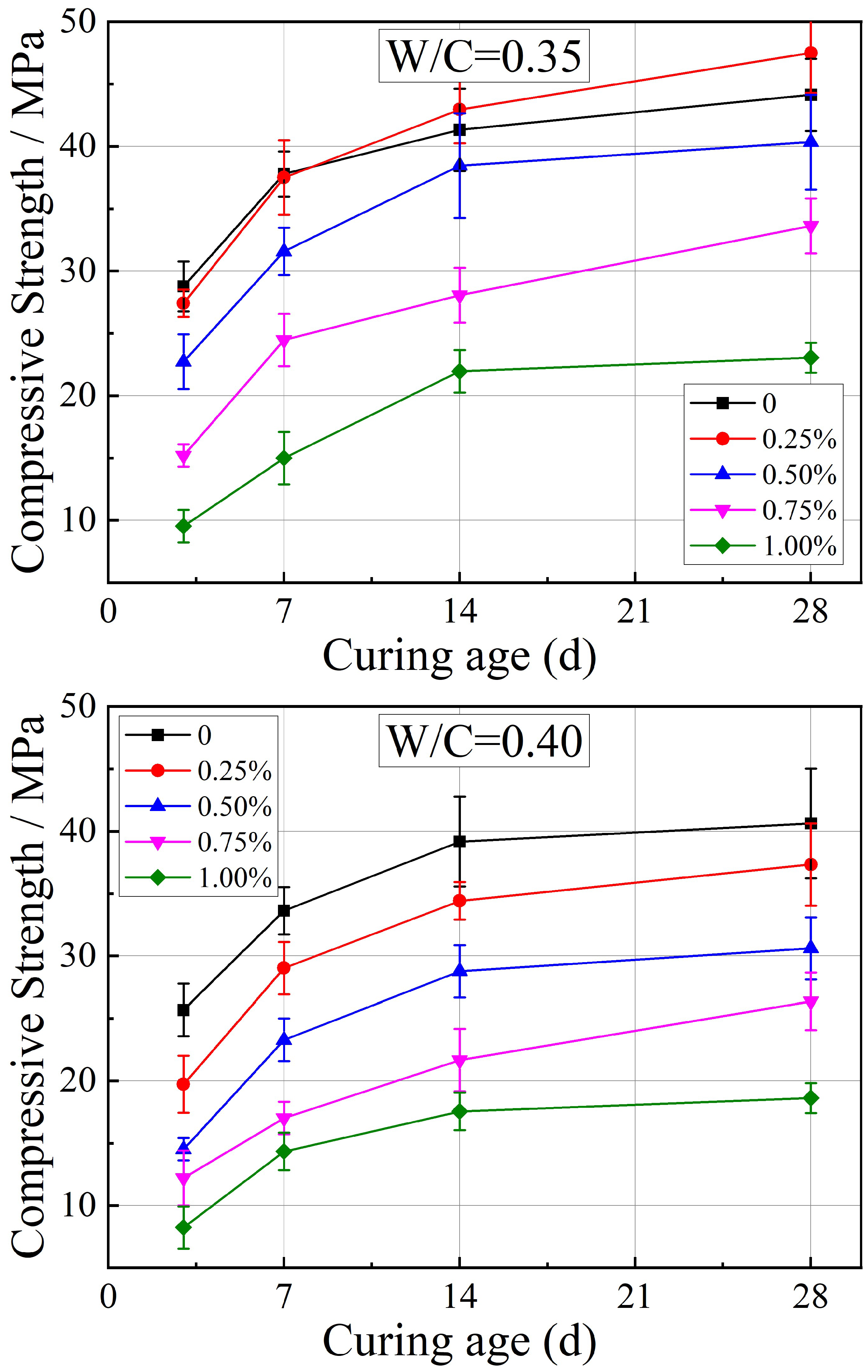
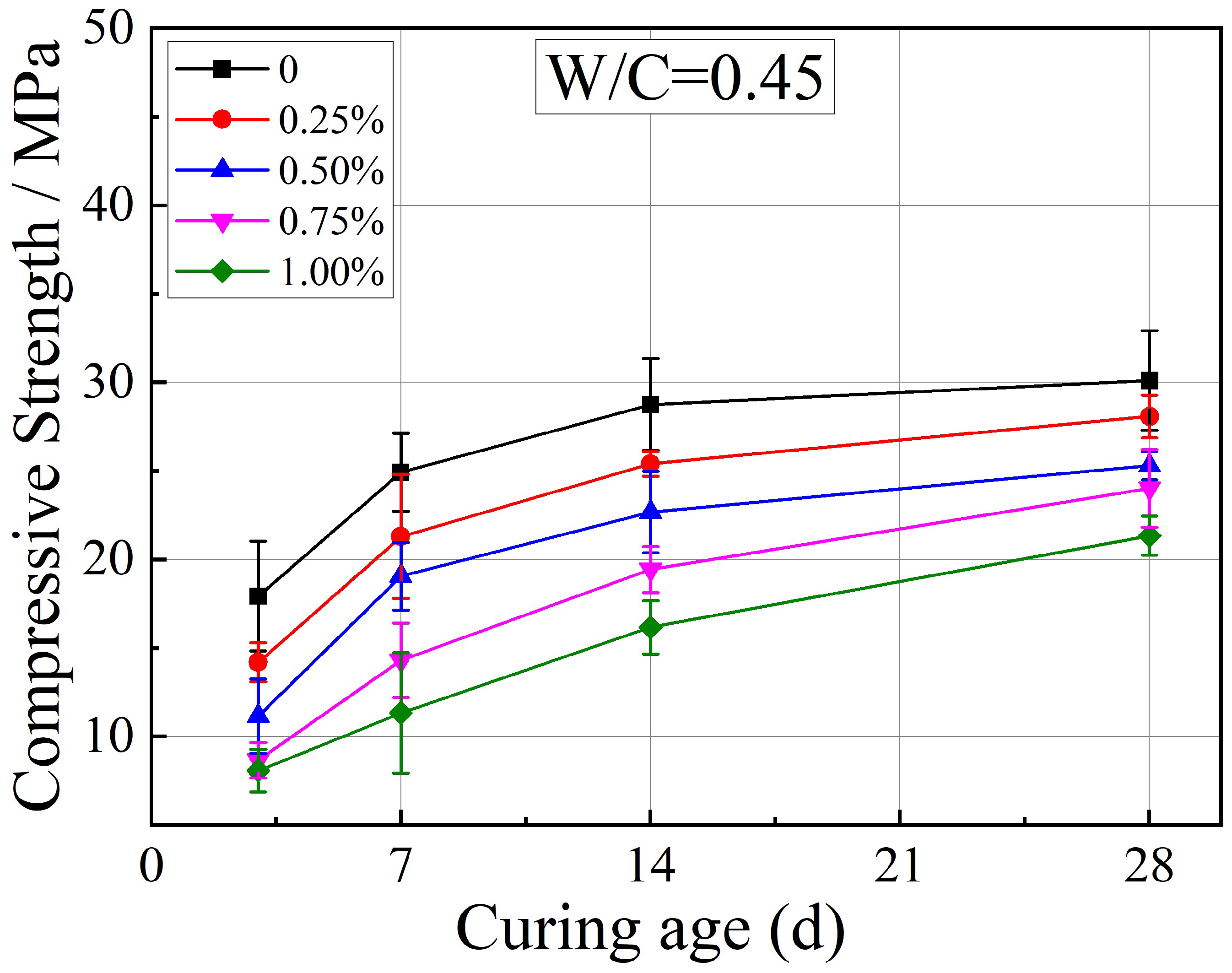
The unconfined compressive strength (UCS) results for different water-to-cement ratios and SAP components are presented in Figure 2. In Figure 2, the negative influence of SAP on the unconfined compressive strength (UCS) is obvious. The reason for this behavior is that the additions of extra entrained water promoted cement hydration, but the W/C ratios were elevated [30,31]. Meanwhile, the empty voids remained in the matrix after the dewatering of the SAP particles, and the weakening effect of SAP voids overrode the extensive hydration of cement hydration and the development of strength [12,25].
However, there was a special case in this study. In Figure 2, when the WC was under 0.35, the 14 d and 28 d UCSs increased (41.323 MPa to 44.958 MPa, and 44.131 MPa to 46.498 MPa, respectively) when the amounts of SAP changed from 0 to 0.25%. There was likely not enough capillary water for unrestricted hydration of the cement when the W/C was 0.35. According to the Powers’ model, at complete hydration, 1 g of cement would bind approximately 0.23 g of water chemically and 0.19 g of gel water [16,31]. Complete and unimpeded hydration was possible at W/C ratios above 0.42 (0.23 + 0.19). If a small cement slurry sample was hydrated underwater, the volume reduction due to chemical shrinkage would be replaced by imbibed water from the surroundings. At a W/C lower than 0.42, free access to water would increase the maximum degree of hydration. The total W/C ratio reached 0.4 when 0.25% SAP was added to the matrix, which is close to the requirement for complete hydration. However, the excessive addition of SAP will affect the mechanical properties of the cement, because SAP reduces the fluidity of the cement and the W/C ratio needs to be improved to ensure the performance of cement slurry, and SAP releases absorbed water will produce a lot of voids in the stone body.
When the W/C was under 0.35, the cement without SAP showed an increase in UCS of 91.4% at 28 d compared with the additional rate of 1%, and it was an exaggerated 201.61% at 3 d. The corresponding data were 118.13% and 177.79%, 41.02% and 122.18% under a W/C of 0.4 and 0.45, respectively. It has been proven that the lower the W/C ratio, the more the UCS is influenced by the addition of SAP, and this effect is more pronounced at an early age [32]. At lower W/C ratios, the increased degree of hydration may counteract the strength loss due to macro-pore formation. At higher W/C ratios, the water required for hydration is sufficient and the entrained water only brings in excess water at an early age, resulting in a phase in which more voids coexist with more water. At the late stage, the water released from the SAP results in continued hydration, thus decreasing the micro-porosity, then the UCS is improved to a certain extent.

3.1.2. Flexural Strength

The results of the flexural strength under different water-to-cement ratios and SAP components are shown in Figure 3. A slight reduction was observed in the flexural strength of the samples from 7.03 MPa to 6.19 MPa with a W/C ratio of 0.4, and from 5.48 MPa to 5.36 MPa with a W/C ratio of 0.45, containing 0% SAP and 0.25% SAP at 28 d, respectively. It can be observed that the trend of flexural strength was almost the same as the UCS. However, the special case (with a 0.35 W/C ratio) in compressive testing was not suitable for flexural testing. The reason for this is that some voids took place under a compressive force, whereas under a flexural force, the tensile section produced wider cracks due to the rupture of the nearby voids [33].

3.1.3. The Mechanical Properties of Self-Healing

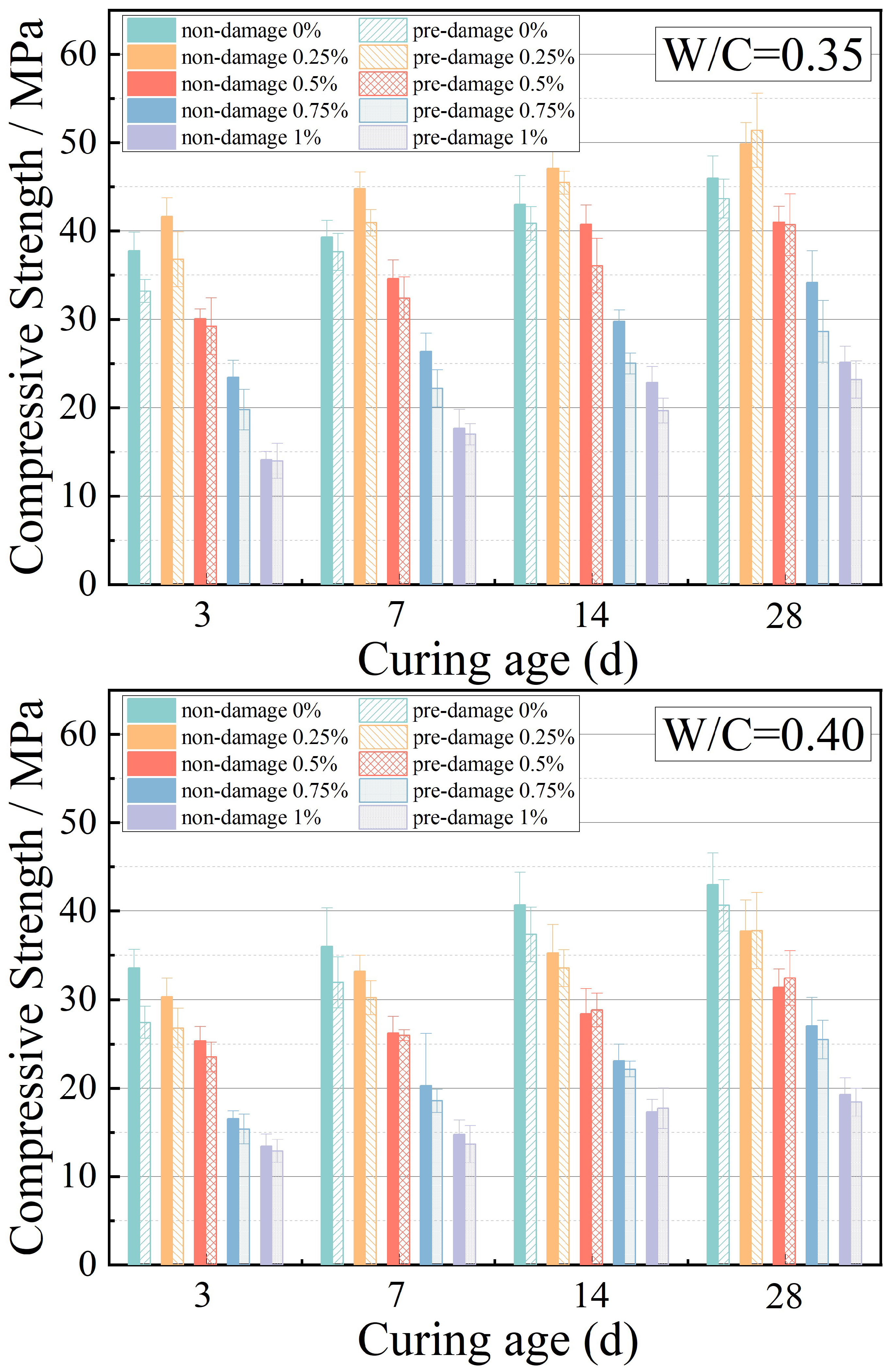
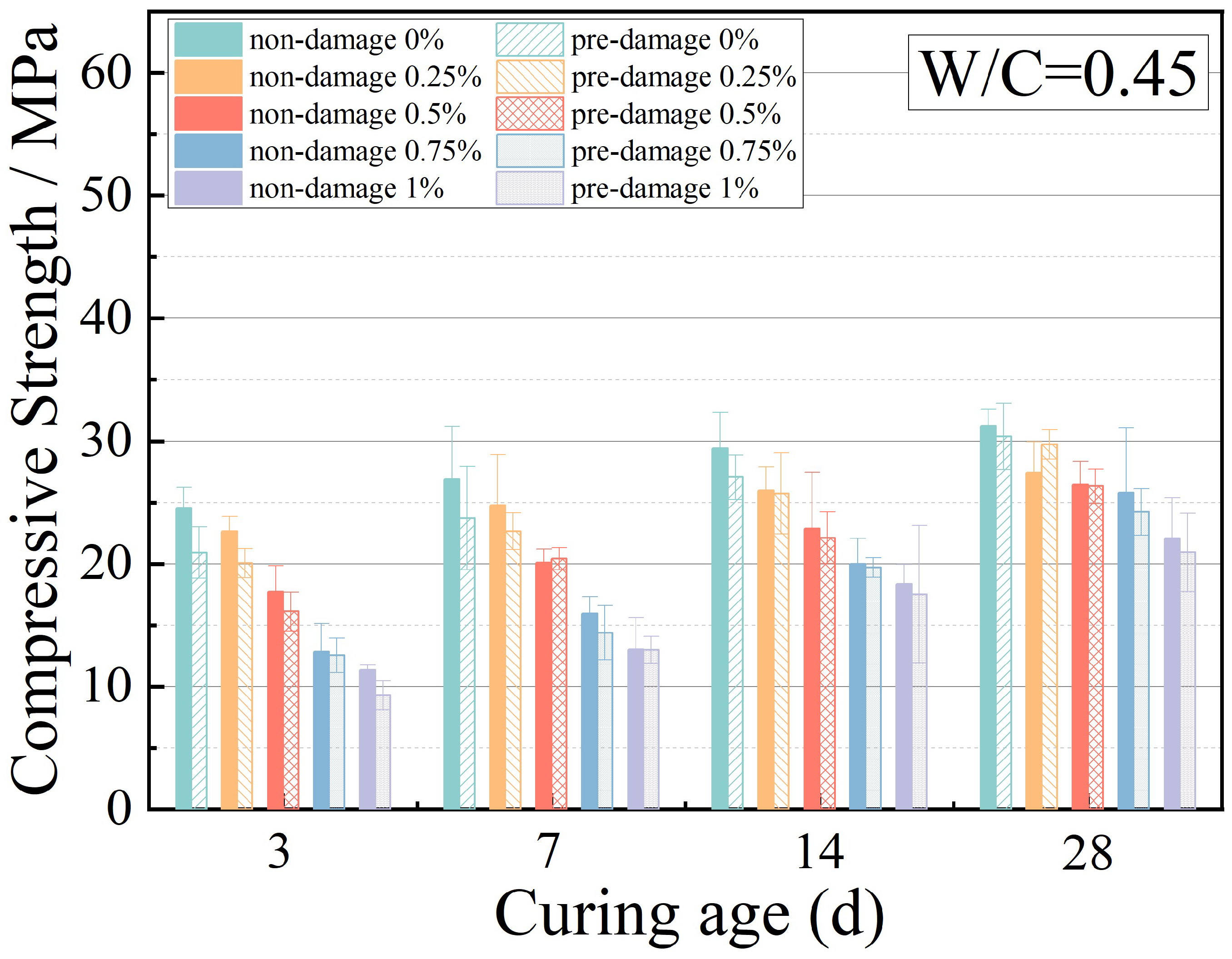
In Figure 4, the unconfined compressive strengths of the pre-damaged samples are in approximate agreement for the different W/C ratios. The UCS of the pre-damaged samples was lower than that of the non-damaged samples before 28 d, but the gap narrowed with the increase in hydration time. When the additional amount of SAP was 0.25%, the UCS of the pre-damaged samples was generally higher than that of the non-damaged samples at a curing age of 28 days. This suggests that the water release speed was accelerated when compressed, and cement self-healing was promoted. However, for the samples without SAP, there was no additional water for continuous self-healing after pre-damaged treatment, thus there was failure for full recovery of UCS. In addition, the strength of the recovery of the pre-damaged samples mixed with too much SAP failed to reach the expected level as a result of SAP voids and excess water.

3.2. Pore Structure

3.2.1. Porosity

The influence of the entrained water and pre-damaged state on the microstructure was studied using MIP. The investigations were performed at ages of 3 d, 7 d, 14 d, and 28 d under the 0.35 W/C ratio, and the amounts of SAP used were 0, 0.25%, 0.5%, 0.75%, and 1%.
As shown in Figure 5, the porosity presented a downward trend with the increase in age. With the development of cement hydration, the hydration products gradually increased, the microstructure became denser, and the porosity decreased. Moreover, the internal structure became more porous because of the addition of SAP. Extra entrained water led to an increase in the overall W/C ratio, which subsequently increased the porosity [18,34]. The formation of SAP voids is another reason the porosity will increase [18,22,25]. In addition, micro-cracks appeared in the matrix after pre-damage, leading to an increase in porosity. The pore diameter distribution of the cement samples with a W/C ratio of 0.35 was analyzed in detail to assist the study.

3.2.2. Pore Diameter Distribution

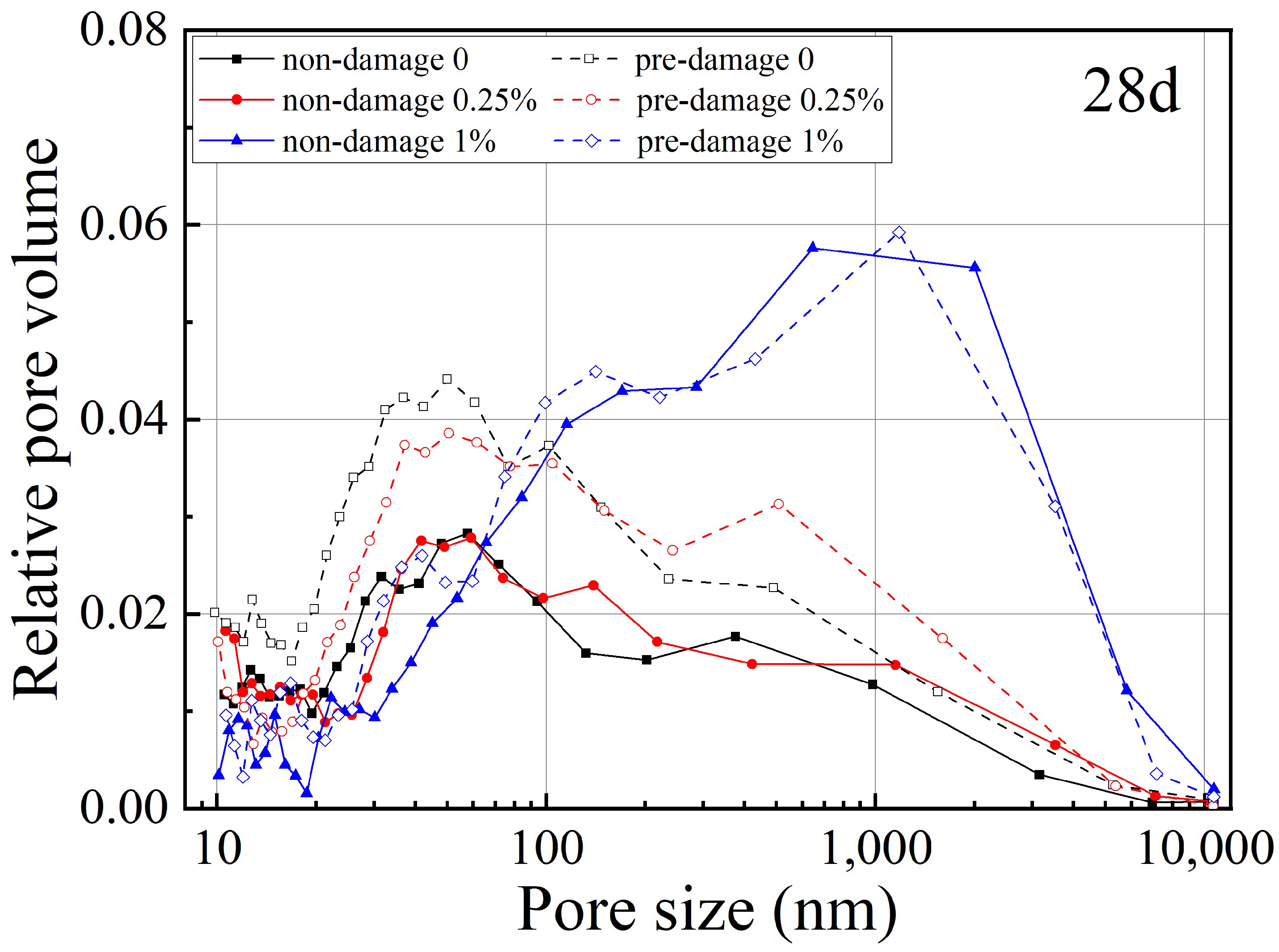
The pore diameter distribution is shown in Figure 6. A logarithmically scaled axis for the abscissa was used as the curves were too close to each other.
As shown in Figure 6, the addition of SAP increased the volume of the small capillary pores (<20 μm) and large capillary pores (>100 μm), and significantly reduced the former with the increase in age. In the early stage of cement hydration, part of the free water released from SAP formed capillary pores, which reduced the compactness of the stone body. In the later stage, the pore volume of SAP decreased significantly due to the influence of the humidity gradient. The water released by SAP caused the cement to continue to hydrate and reduce the porosity. The voids increased with the addition of SAP, resulting in a general increase in large pores.

3.2.3. Compressive Strength–Porosity Relationship Representation by Balshin Equation

Porosity is the main factor affecting the strength of concrete, and its increase will lead to a decrease in mechanical strength [35,36,37]. Balshin’s compressive strength–porosity equation is commonly used to characterize the relationship between them, as follows:
σ = σ 0 ( 1 p ) n
where σ = compressive strength of sample with porosity p; σ 0 = an intrinsic strength, namely, compressive strength at zero porosity; p = porosity; and n = a power coefficient.
The Balshin equation and regression coefficient are shown in Table 5. From Table 5, it can be seen that the regression n coefficients were less than 0.5 except, for the non-damaged samples with 0 and 0.25% SAP, and certain parts were less than 0.2. There was a relatively weak quantitative relationship between UCS and porosity, and it could not be completely characterized by the Balshin equation.
In the process of measuring the porosity of the SAP-modified cement by MIP, the mercury intruded by high pressure destroyed the micro-pores structure, which caused errors in the detection results of the pore size distribution. The SAP particle sizes in the study were up to 300 μm and exceeded the range of mercury injectors. After absorbing the cement slurry, the SAP expanded to nearly 1 mm. Although the SAP voids decreased with the process of cement hydration, they were still large, as shown in Figure 7. Such large voids were destroyed during the preparation of the mercury injection sample, resulting in a low porosity [38,39]. In addition, micro-cracks appeared inside the cement due to the pre-damage and were filled at the low-pressure stage. This part was not calculated in the results, leading to a large deviation in porosity.

3.3. Microstructure

3.3.1. SEM Analysis

Figure 8 shows the micromorphology and microstructure of the samples with the addition of 1% SAP at 28 d under the different W/C ratios (0.35 and 0.45). The microstructure of the sample with the 0.35 W/C ratio (Figure 8a) was dense and had more C-S-H gel [40]. This is because the second hydration reaction was due to the addition of SAP. In Figure 8b, the pores were more and the diameter was larger. Net-like hydration products grew freely, which took up half of the surface. The surface of the sample was not dense and the structure was relatively loose. Therefore, excess water in SAP caused the microstructures of the samples to be amorphous and loose, the whole bonding performance was poor and obvious cracks and pores existed. These factors determined the samples’ low flexural and compressive strengths, which was in accordance with the changing situation of UCS in Section 3.1.
As shown in Figure 9, after the application of pre-damage, cracks appeared in the sample with a width of tens of microns (Figure 9a > 15 μm, and Figure 9b > 20 μm). The cracks were much wider than the pores generated by the cement hydration, and would not be measured in the mercury injection. The reason for this is that porosity is calculated based on the difference in the weight of the mercury entering the sample under low and high pressure. In particular, the pores that mercury can enter are 10–200 μm under low pressure, while they are 0.01–10 μm under high pressure. Thus, the cracks shown in Figure 9 would be filled at low pressure, causing the porosity calculation result to be incorrect.
Figure 10 shows the micromorphology and self-healing status of the crack position of the pre-damage samples with the addition of 0%, 0.25%, and 1% SAP at 28 d at a W/C ratio of under 0.35. As shown in Figure 10a, even if the samples did not have SAP, the cracks recovered to a certain extent after 28 d. This was due to the inherent self-healing properties of cement-based materials. Several possible causes could be responsible for the self-healing phenomena: (1) formation of calcium carbonate or calcium hydroxide; (2) blocking cracks by impurities in the water and loss of concrete particles resulting from crack spalling; (3) further hydration of the unreacted cement or cementitious materials; and (4) expansion of the hydrated cementitious matrix in the crack flanks (swelling of C–S–H). However, because of the lack of SAP that would continue to provide subsequent water for cement hydration, the C-S-H cement produced less, and there were still cracks. As shown in Figure 10b,c, although the cracks were not similar, the degree of healing was greater than that in Figure 10a, and many ettringites (AFt) and C-S-H gels could be found in the cracks. These hydration products are the fundamental reason for the strength restoration of pre-damaged samples with 0.25% SAP. After 28 d of repair, the cracks exhibited self-healing, and the crack width reduced significantly with the addition of 1% SAP, as shown in Figure 10d. During the self-healing process, several needle-like and flocculent repair products were produced on the SAP surface and in the crack. However, the structure at the crack location was loose after self-healing because the total W/C ratio was 0.55 with 1% SAP added for more than the water needed theoretically (0.42). Thus, the voids were more than in Figure 10b,c, and the cracks would extend in this direction when secondary damage occurred. In summary, when the water-cement ratio was 0.35 and the SAP content was 0.25%, the SAP-modified concrete had the best self-healing effect and the densest structure.

3.3.2. EDS Analysis

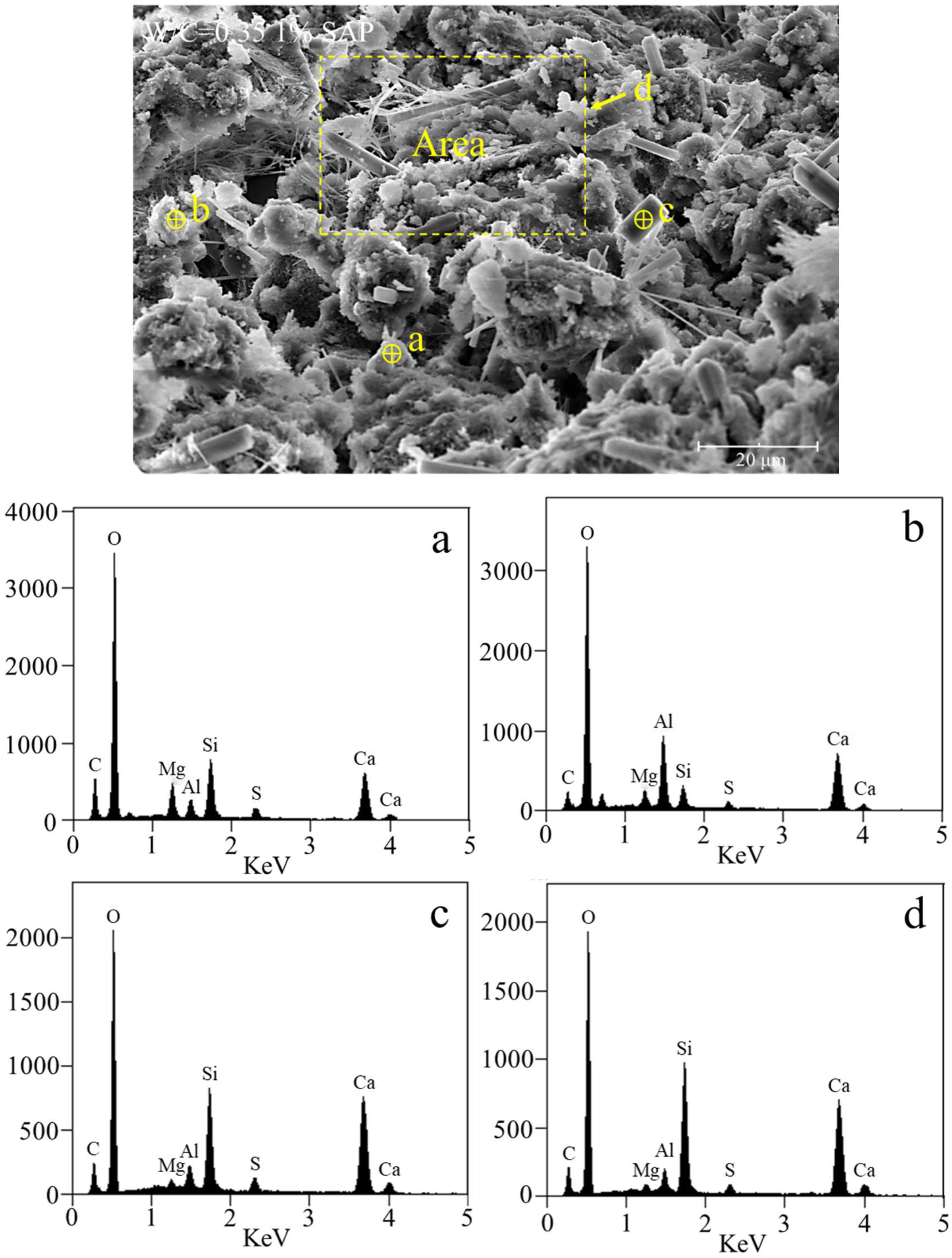
The elemental compositions of points A, B, and C, and area D of the samples with a water–cement ratio of 0.35 and SAP content of 1% were measured using the EDS method. As shown in Figure 11, the particles contained a sufficient amount of carbon. There was no carbon in the cement, sand, or water, and only a small amount in the SAP. According to the element contents in Table 2 and the mix proportion in Table 4, the calculated carbon should be 0.016%, which is far less than the data in Table 6. The reason for this is that CO2 enters the cracks and combines with Ca(OH)2 to produce the calcium carbonate (CaCO3) to fill the cracks. The number and width of cracks in the samples with 1% SAP generated by the pre-damage were larger. Although more CaCO3 was produced, much more is needed to heal the cracks [41].

4. Conclusions

The properties of pre-damaged concrete proportioned with different W/C ratios and SAP components were investigated. Based on the results presented in this paper, the following concluding remarks can be drawn:
(1)
SAP reduces the mechanical properties of SAP-modified concrete under the same W/C ratio. However, a small amount of SAP can improve the later strength when the W/C ratio is under 0.35.
(2)
The lower the W/C ratio, the more mechanical property is influenced by the addition of SAP, and this effect is more pronounced at an early age.
(3)
After 28 d of curing, the UCS of the pre-damaged sample is generally lower than that of the non-damaged sample, except for with the addition of 0.25% SAP.
(4)
The addition of SAP increases the volume of the small capillary pores (<20 μm) and large capillary pores (>100 μm), and significantly reduces the former with the increase in age.
(5)
The water released by SAP promotes the formation of C-S-H gel, and AFt in cracks is the main reason for cement self-healing. CO2 enters the cracks and combines with Ca(OH)2 to produce calcium carbonate (CaCO3), which is another reason.
(6)
The SAP-modified concrete has the best self-healing effect and the densest structure, when the W/C ratio is 0.35 and the SAP content is 0.25%.
This study summarizes the influence of the W/C ratio and SAP content on the self-healing of cement and tries to find the best mix proportion. For future engineering practice, the self-healing of cracks in cement-based materials can be achieved by SAP modification of cement. This technology has the characteristics of a simple preparation process and wide engineering application.

Author Contributions

B.C.: conceptualization, methodology, writing—review and editing. X.L.: writing—original draft, data curation, and investigation. Y.L.: formal analysis and investigation. M.C.: supervision, funding acquisition, validation. S.D.: investigation. All authors have read and agreed to the published version of the manuscript.

Funding

This work was supported by the National Key Research and Development Program of China (grant numbers 2019YFC1805402 and 2020YFB1600504), and the General Program of Natural Science Foundation of China (grant number 51879152).

Institutional Review Board Statement

Not applicable.

Informed Consent Statement

Not applicable.

Data Availability Statement

The data that support the findings of this study are available from the corresponding author upon reasonable request.

Conflicts of Interest

The authors declare no conflict of interest.

References

  1. Wang, X.; Liu, L.; Fu, R.; Sun, X. Newly developed pressure adaptable concrete lining for high pressure hydraulic tunnels. Tunn. Undergr. Space Technol. 2020, 105, 103570. [Google Scholar] [CrossRef]
  2. Yang, L.; Yao, Z.; Xue, W.; Wang, X.; Kong, W.; Wu, T. Preparation, performance test and microanalysis of hybrid fibers and microexpansive high-performance shaft lining concrete. Constr. Build. Mater. 2019, 223, 431–440. [Google Scholar] [CrossRef]
  3. Cugat, V.; Cavalaro, S.; Bairán, J.; de la Fuente, A. Safety format for the flexural design of tunnel fibre reinforced concrete precast segmental linings. Tunn. Undergr. Space Technol. 2020, 103, 103500. [Google Scholar] [CrossRef]
  4. Wu, M.; Hu, X.; Zhang, Q.; Cheng, W.; Xue, D.; Zhao, Y. Application of bacterial spores coated by a green inorganic cementitious material for the self-healing of concrete cracks. Cem. Concr. Compos. 2020, 113, 103718. [Google Scholar] [CrossRef]
  5. García, R.; Pérez Caldentey, A. Influence of type of loading (tension or bending) on cracking behaviour of reinforced concrete elements. Experimental study. Eng. Struct. 2020, 222, 111134. [Google Scholar] [CrossRef]
  6. Lawrence, P.; Cyr, M.; Ringot, E. Mineral admixtures in mortars: Effect of inert materials on short-term hydration. Cem. Concr. Res. 2003, 33, 1939–1947. [Google Scholar] [CrossRef]
  7. Li, Z.; Ding, S.; Yu, X.; Han, B.; Ou, J. Multifunctional cementitious composites modified with nano titanium dioxide: A review. Compos. Part A Appl. Sci. Manuf. 2018, 111, 115–137. [Google Scholar] [CrossRef]
  8. Wang, K.; Jansen, D.C.; Shah, S.P.; Karr, A.F. Permeability study of cracked concrete. Cem. Concr. Res. 1997, 27, 381–393. [Google Scholar] [CrossRef] [Green Version]
  9. Ray, I.; Parish, G.C.; Davalos, J.F.; Chen, A. Effect of Concrete Substrate Repair Methods for Beams Aged by Accelerated Corrosion and Strengthened with CFRP. J. Aerospace. Eng. 2011, 24, 227–239. [Google Scholar] [CrossRef]
  10. Nobili, A.; Falope, F.O. Impregnated Carbon Fabric-Reinforced Cementitious Matrix Composite for Rehabilitation of the Finale Emilia Hospital Roofs: Case Study. J. Compos. Constr. 2017, 21, 050170014. [Google Scholar] [CrossRef]
  11. He, Z.; Shen, A.; Guo, Y.; Lyu, Z.; Li, D.; Qin, X.; Zhao, M.; Wang, Z. Cement-based materials modified with superabsorbent polymers: A review. Constr. Build. Mater. 2019, 225, 569–590. [Google Scholar] [CrossRef]
  12. Ma, X.; Zhang, J.; Liu, J. Review on Superabsorbent Polymer as Internal Curing Agent of High Performance Cement-based Material. J. Chin. Ceram. Soc. 2015, 43, 1099–1110. [Google Scholar]
  13. Dutkiewicz, J.K. Superabsorbent materials from shellfish waste? A review. J. Biomed. Mater. Res. 2002, 63, 373–381. [Google Scholar] [CrossRef]
  14. Mignon, A.; Snoeck, D.; Halluin, K.; Balcaen, L.; Vanhaecke, F.; Dubruel, P.; Vlierberghe, S.V.; Belie, N.D. Alginate biopolymers: Counteracting the impact of superabsorbent polymers on mortar strength. Constr. Build. Mater. 2016, 110, 169–174. [Google Scholar] [CrossRef]
  15. Riyazi, S.; Kevern, J.T.; Mulheron, M. Super absorbent polymers (SAPs) as physical air entrainment in cement mortars. Constr. Build. Mater. 2017, 147, 669–676. [Google Scholar] [CrossRef]
  16. Jensen, O.M.; Hansen, P.F. Water-entrained cement-based materials: I. Principles and theoretical background. Cem. Concr. Res. 2001, 31, 647–654. [Google Scholar] [CrossRef]
  17. Hasholt, M.T.; Jensen, O.M.; Kovler, K.; Zhutovsky, S. Can superabsorent polymers mitigate autogenous shrinkage of internally cured concrete without compromising the strength? Constr. Build. Mater. 2012, 31, 226–230. [Google Scholar] [CrossRef]
  18. Snoeck, D.; Schaubroeck, D.; Dubruel, P.; De Belie, N. Effect of high amounts of superabsorbent polymers and additional water on the workability, microstructure and strength of mortars with a water-to-cement ratio of 0.50. Constr. Build. Mater. 2014, 72, 148–157. [Google Scholar] [CrossRef]
  19. Snoeck, D.; Steuperaert, S.; Van Tittelboom, K.; Dubruel, P.; De Belie, N. Visualization of water penetration in cementitious materials with superabsorbent polymers by means of neutron radiography. Cem. Concr. Res. 2012, 42, 1113–1121. [Google Scholar] [CrossRef]
  20. De Rooij, M.; Van Tittelboom, K.; De Belie, N.; Schlangen, E. State-of-the-Art Report of RILEM Technical Com-mittee 221-SHC: Self-Healing Phenomena in Cement-Based Materials; Springer: Berlin/Heidelberg, Germany, 2013. [Google Scholar]
  21. Hong, G.; Choi, S. Modeling rapid self-sealing of cracks in cementitious materials using superabsorbent polymers. Constr. Build. Mater. 2018, 164, 570–578. [Google Scholar] [CrossRef]
  22. Lee, H.; Wong, H.; Buenfeld, N. Self-sealing of cracks in concrete using superabsorbent polymers. Cem. Concr. Res. 2016, 79, 194–208. [Google Scholar] [CrossRef]
  23. Snoeck, D.; Van Tittelboom, K.; Steuperaert, S.; Dubruel, P.; De Belie, N. Self-healing cementitious materials by the combination of microfibres and superabsorbent polymers. J. Intell. Mater. Syst. Struct. 2014, 25, 13–24. [Google Scholar] [CrossRef] [Green Version]
  24. Ma, X.; Liu, J.; Wu, Z.; Shi, C. Effects of SAP on the properties and pore structure of high performance cement-based materials. Constr. Build. Mater. 2017, 131, 476–484. [Google Scholar] [CrossRef]
  25. Kang, S.; Hong, S.; Moon, J. The effect of superabsorbent polymer on various scale of pore structure in ultra-high performance concrete. Constr. Build. Mater. 2018, 172, 29–40. [Google Scholar] [CrossRef]
  26. Li, M.; Wang, Y.-J.; Wang, W.-B.; Tian, Q.; Liu, J.-P. Quantitative characterisation of absorption capacity and dosage of SAP in cement paste. Adv. Cem. Res. 2016, 28, 518–528. [Google Scholar] [CrossRef]
  27. Mignon, A.; Vagenende, M.; Martins, J.; Dubruel, P.; Van Vlierberghe, S.; De Belie, N. Development of amine-based pH-responsive superabsorbent polymers for mortar applications. Constr. Build. Mater. 2017, 132, 556–564. [Google Scholar] [CrossRef]
  28. Beushausen, H.; Gillmer, M. The use of superabsorbent polymers to reduce cracking of bonded mortar overlays. Cem. Concr. Compos. 2014, 52, 1–8. [Google Scholar] [CrossRef]
  29. Nestle, N.; Kühn, A.; Friedemann, K.; Horch, C.; Stallmach, F.; Herth, G. Water balance and pore structure development in cementitious materials in internal curing with modified superabsorbent polymer studied by NMR. Microporous Mesoporous Mater. 2009, 125, 51–57. [Google Scholar] [CrossRef]
  30. Schröfl, C.; Mechtcherine, V.; Gorges, M. Relation between the molecular structure and the efficiency of superabsorbent polymers (SAP) as concrete admixture to mitigate autogenous shrinkage. Cem. Concr. Res. 2012, 42, 865–873. [Google Scholar] [CrossRef]
  31. Jensen, O.M.; Hansen, P.F. Water-entrained cement-based materials II. Experimental observations. Cem. Concr. Res. 2002, 32, 973–978. [Google Scholar] [CrossRef]
  32. Dudziak, L.; Mechtcherine, V. Enhancing early-age resistance to cracking in high-strength cement-based materials by means of internal curing using super absorbent polymers. In International RILEM Conference on Material Science 2010, Aachen, Germany, 6–8 September 2010; Brameshuber, W., Ed.; RILEM Publications: Marne la Vallée, France, 2010; pp. 129–139. [Google Scholar]
  33. Gupta, S.; Kua, H.W.; Pang, S.D. Combination of polypropylene fibre and superabsorbent polymer to improve physical properties of cement mortar. Mag. Concr. Res. 2018, 70, 350–364. [Google Scholar] [CrossRef]
  34. Olawuyi, B.J.; Boshoff, W. Influence of SAP content and curing age on air void distribution of high performance concrete using 3D volume analysis. Constr. Build. Mater. 2017, 135, 580–589. [Google Scholar] [CrossRef]
  35. Hajimohammadi, A.; Ngo, T.; Mendis, P. Enhancing the strength of pre-made foams for foam concrete applications. Cem. Concr. Compos. 2018, 87, 164–171. [Google Scholar] [CrossRef]
  36. Nambiar, E.K.K.; Ramamurthy, K. Models for strength prediction of foam concrete. Mater. Struct. 2008, 41, 247–254. [Google Scholar] [CrossRef]
  37. Kearsley, E.P.; Wainwright, P.J. The effect of porosity on the strength of foamed concrete. Cem. Concr. Res. 2002, 32, 233–239. [Google Scholar] [CrossRef]
  38. Diamond, S. Mercury porosimetry: An inappropriate method for the measurement of pore size distributions in cement-based materials. Cem. Concr. Res. 2000, 30, 1517–1525. [Google Scholar] [CrossRef]
  39. Meddah, M.S.; Tagnit-Hamou, A. Pore Structure of Concrete with Mineral Admixtures and Its Effect on Self-Desiccation Shrinkage. ACI Mater. J. 2009, 106, 241–250. [Google Scholar]
  40. Dang, J.; Zhao, J.; Du, Z. Effect of Superabsorbent Polymer on the Properties of Concrete. Polymers 2017, 9, 672. [Google Scholar] [CrossRef] [Green Version]
  41. Justs, J.; Wyrzykowski, M.; Winnefeld, F.; Bajare, D.; Lura, P. Influence of superabsorbent polymers on hydration of cement pastes with low water-to-binder ratio. J. Therm. Anal. 2014, 115, 425–432. [Google Scholar] [CrossRef]
Figure 1. Macrograph and micrograph of SAP.
Processes 10 02333 g001
Figure 2. Unconfined compressive strength of samples with different W/C ratios (0.35, 0.4, and 0.45), ages (3 d, 7 d, 14 d, and 28 d), and SAP components (0%, 0.25%, 0.5%, 0.75%, and 1%).
Processes 10 02333 g002aProcesses 10 02333 g002b
Figure 3. Flexural strength of samples with different W/C ratios (0.35, 0.4, and 0.45), ages (3 d, 7 d, 14 d, and 28 d), and SAP components (0%, 0.25%, 0.5%, 0.75%, and 1%).
Processes 10 02333 g003aProcesses 10 02333 g003b
Figure 4. Unconfined compressive strengths of samples in non-damage and pre-damage states at different W/C ratios (0.35, 0.4, and 0.45), ages (3 d, 7 d, 14 d, and 28 d), and SAP components (0%, 0.25%, 0.5%, 0.75%, and 1%).
Processes 10 02333 g004aProcesses 10 02333 g004b
Figure 5. The porosity of samples in non-damage and pre-damage states under a 0.35 W/C ratio, with different ages (3 d, 7 d, 14 d, and 28 d) and SAP components (0%, 0.25%, 0.5%, 0.75%, and 1%).
Processes 10 02333 g005
Figure 6. The relative pore volume of samples in non-damage and pre-damage states at a W/C ratio under 0.35, with different ages (7 d, 14 d, and 28 d) and SAP components (0%, 0.25%, and 1%).
Processes 10 02333 g006aProcesses 10 02333 g006b
Figure 7. The large visible voids in the cement sample surface.
Processes 10 02333 g007
Figure 8. Micromorphology and microstructure of samples with the addition of 1% SAP at 28 d: (a) W/C = 0.35 (b) W/C = 0.45.
Processes 10 02333 g008
Figure 9. Micromorphology and microstructure of the samples with the pre-damage state: (a) crack width of 10–20 μm, (b) crack width of 20–30 μm.
Processes 10 02333 g009
Figure 10. Micromorphology and microstructure of the samples with a W/C ratio of 0.35 at 28 d: (a) 0% SAP, (b,c) 0.25% SAP, and (d) 1% SAP.
Processes 10 02333 g010
Figure 11. The EDS analysis of the samples with the W/C ratio of 0.35 at 28 d: (a) EDS curve of point a, (b) EDS curve of point b, (c) EDS curve of point c, (d) EDS curve of area d.
Processes 10 02333 g011
Table 1. Chemical composition of ASTM Type Ⅰ Portland cement.
Chemical CompositionSiO2Fe2O3Al2O3CaOMgOSO3Loss on Ignition
Contents (wt.%)19.454.425.8463.314.382.60.56
Table 2. The element content of SAP.
ElementCONaSiSOthers
Contents (wt.%)22.1649.2521.671.783.311.83
Table 3. Particle size distribution and physical properties of the SAP and sand.
D10 (μm)D50 (μm)D90 (μm)Absorption Capacity (g/g)Absorption Time (S)
SAP161.73 ± 1.82217.53 ± 1.69296.22 ± 3.9720 ± 112 ± 2
Sand221.47 ± 2.21607.32 ± 4.861528.91 ± 9.74--
Table 4. Mix proportion.
SamplesIndustrial Solid Waste Components 1 (wt.%)SAP Components 2 (wt.%)Water (wt.%)
CementSandW1 3W2 4Ws 5
11200.3500.35
2120.250.350.050.4
3120.50.350.10.45
4120.750.350.150.5
51210.350.20.55
61200.400.4
7120.250.40.050.45
8120.50.40.10.5
9120.750.40.150.55
101210.40.20.6
111200.4500.45
12120.250.450.050.5
13120.50.450.10.55
14120.750.450.150.6
151210.450.20.65
Note: 1 cement/sand mass ratio; 2 SAP/cement mass ratio; 3 water1/cement mass ratio; 4 water2/cement mass ratio; 5 waters/cement mass ratio (water1 is the original water demand under different water-cement ratios, water2 is the additional amount of entrained water by SAP, waters is actual the water demand: waters = water1 + water2).
Table 5. The Balshin equation and regression coefficient.
SAP(%)Balshin Equationσ0nRegression Coefficient
non-damage0 σ = 60 . 28 × ( 1 p ) 1 . 86 60.281.860.89
0.25 σ = 65 . 28 × ( 1 p ) 1 . 82 65.281.820.93
0.5 σ = 120 . 06 × ( 1 p ) 4 . 82 120.064.820.30
0.75 σ = 64 . 46 × ( 1 p ) 3 . 18 64.463.180.17
1 σ = 103 . 30 × ( 1 p ) 5 . 79 103.305.790.29
pre-damage0 σ = 74 . 24 × ( 1 p ) 2 . 99 74.242.990.54
0.25 σ = 77 . 43 × ( 1 p ) 2 . 58 77.432.580.50
0.5 σ = 73 . 01 × ( 1 p ) 3.02 73.013.020.45
0.75 σ = 45 . 61 × ( 1 p ) 2 . 39 45.612.390.17
1 σ = 44 . 47 × ( 1 p ) 2 . 91 44.472.910.24
Table 6. The elements in the areas of the sample scanned by EDS.
COMgAlSiSCaOthers
a4.9351.203.642.268.592.5124.052.82
b1.9547.001.668.352.831.3026.6810.23
c2.7745.450.61.9610.172.1536.370.53
d2.6344.880.461.7013.031.3835.180.76
Publisher’s Note: MDPI stays neutral with regard to jurisdictional claims in published maps and institutional affiliations.