Abstract
Achieving curved crease surfaces is a current challenge for designers, the field still underexplored. The curve on which the bending is performed can present extremely complicated shapes that must be accurately generated through various technological processes. For this aim, a planar mechanism consisting of an ellipsograph, a conchoidograph and an RRR dyad—whose inner joint generates the targeted connecting rod curve—was proposed in this paper. Parametrizing the lengths of the elements of the RRR dyad, the correlation coefficient of the rotations of the leading elements and the directions of these movements result in different connecting rod curves, which can be used to obtain the folded surfaces; the optimization, according to various criteria, will be explored for the automatic generation of some design solutions. With the help of the Altair program, for some given geometrical data of the mechanism, both the drawing of the curve on plates of different initial shapes and the simulation of their folding by applying compression forces on the bounding surfaces were carried out. By cutting the deformed shape, folded surface units used in tessellations are obtained.
1. Introduction
The fascinating and elegant shapes of various geometric volumes can be obtained through deformation processes. There are two ways to deform a flat sheet without stretching or breaking it, namely bending and folding. The two methods, bending and folding, can be combined to obtain a complex surface (e.g., [1,2]).
When we try to form a surface by pure bending, the shape is limited to simple geometries, such as cones, cylinders, and tangent surfaces [3].
When a surface is deformed by folding, it can be made along a straight line or a curve. Straight line folding transfigures the sheet into a polyhedral surface with a sudden change in surface direction; by contrast, the curved folding, generically called “free forms”, turns the sheet into a smooth curved surface with the gradual change in direction, obtaining unconventional complex three-dimensional modern spatial forms by the hybrid deformation [4]. In this form, the thin sheet gains strength and becomes more resistant to deformation [5].
In the field of architecture, folding along straight lines has been taken as a reference for its kinetic properties, for the elegance of geometric shapes, and for its ability to rationalize the creative process, such as for its ability to combine form and movement in a functional way [6]. In [7], the development of origami kinematics and the application of origami characteristics in various fields is briefly described.
Curved crease folding surfaces have been used relatively recently for various structures, such as: solar panels (e.g., [8,9]) and solid constructions from unfolded surfaces, including for tessellations (e.g., [10]), car designs and long-span roofs (e.g., [3]), decorative art and urban furniture (e.g., [4]), and packing boxes (e.g., [11,12]).
In [3] are partially presented works from the period 1652–2011 related to the folding on curves, with applications in art and industrial designs; the studies continue until the current period.
Depending on the technological process, sheets deformed by bending or folding can result in a flexible or rigid structure. Several execution technologies can be used, such as: perforating or tearing the folds with a laser cutter [4,13], bending or pressing by plastic deformation [14,15], and using controlled robots through software [16]. The last of them allows to obtain completely new aesthetic elements by varying the design parameters.
Computer techniques, which are associated with individualized manufacturing methods, are used to find “freeform” solutions (e.g., [4]) or to generate flat-foldable patterns (e.g., [17]).
Specific CAD software and other dedicated programs in the digital design of deformed surfaces were used. In [18], many of the programs based on ParaGen genetic optimization and examples of their use are reviewed. Additionally, other programs have been developed that allow the easy use of curves to obtain folded surfaces, such as: CURVED.IT [5] and CAD Rhino 3D/Grasshopper [14].
Considering the complexity of the domain, the analysis of the curves that determine the folding of the surfaces should not be neglected. Both mathematicians and mechanics have carried out numerous studies on the geometry of curves. These can be processed on numerical control machines if the equations of the curves are known. The mechanisms that generate complex connecting rod curves can be used to obtain the equations of these curves but also for their processing.
In 1951, the book by Hrones and Nelson with connecting rod curves drawn by the articulated quadrilateral mechanism [19] was published in the USA. The authors used graphical methods for kinematic analyses. The method of intersections (lines and circles) was also applied in the study of connecting rod curves of other mechanisms (e.g., [20]).
The appearance and development of computers facilitated the use of analytical and numerical methods for establishing the equations of the connecting rod curves generated by the mechanisms. An impressive number of books and scientific articles have appeared in this field, such as the papers in the Mechanism and Machine Theory journal from the be-ginning of its appearance until now. Additionally, researchers from the University of Craiova have published numerous works in the same domain (e.g., [21,22,23,24]).
The purpose of this work is to obtain and analyze different curved crease surfaces and having the generating curve determined by a planar mechanism.
The lengths of some elements of the mechanism were parameterized, as well as the correlation coefficient of the rotations of its leading elements and the directions of these movements. The mechanism that traces an open, continuous, and aesthetic curve was selected.
The Cartesian coordinates of the selected curve points were transferred to the geometric model of a thin metal sheet. The technological process of obtaining folded surfaces was simulated by applying compressive forces along the contour of the considered geometric model, and the results obtained were interpreted.
2. The Analysis of a Planar Mechanism That Generates Connecting Rod Curves
The planar mechanism in Figure 1, consisting of an ellipsograph, a concoidograph, and a RRR dyad, is considered. Point D of the ellipsograph mechanism ABCDE generates an ellipse, and the points located on element 9 of the concoidograph mechanism FGH generate conchoids [21]. The RRR dyad is coupled by means of joint D to the ellipsograph and by means of joint G to the concoidograph, so that these points move on the ellipse and the conchoid, respectively. On slide 9, points G1 and G2 at equal distances from G were also considered in order to visualize two conchoids diametrically opposed to rotation joint G.
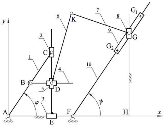
Figure 1.
Connecting rod curve generating mechanism.
Since the mechanism is not overconstrained, the degree of mobility of the mechanism is calculated according to the Chebyshev–Grübler–Kutzbach criterion. The mechanism degree of mobility is 2, and φ and ψ were considered as parameters. The equations for determining the positions of points D, G, G1, G2, and K (Equations (1)–(10)) were written based on the method of vector contours and the method of the lengths.
The movements of the leading elements AB and FG were correlated by Equation (11).
where q is a real constant that is adopted.
Equations (9) and (10) determined two solutions, and one of them was taken into account.
The known geometric data were given in millimeters: AB = 34, BC = 32, AC = 66, XH = 103, XF = 55, and GG1 = GG2 = 20.
To analyze the kinematics of curves that can generate different folded surfaces, a program was created in GWBASIC and run for 20 data sets, keeping the previously mentioned constant and having as variables q and the lengths of elements 6 and 7. After running the program, various trajectories of points D, G1, and G2 were obtained, having the shape an ellipse, respectively, two conchoids with different discontinuities. The mechanism works only on the portions of the continuous ellipse and conchoid, and point K will appropriately describe a part of the entire possible curve. These discontinuities appear in critical operating positions when two elements are collinear. Figure 2, Figure 3, Figure 4, Figure 5, Figure 6, Figure 7, Figure 8, Figure 9, Figure 10, Figure 11, Figure 12, Figure 13, Figure 14, Figure 15, Figure 16, Figure 17, Figure 18, Figure 19, Figure 20 and Figure 21 show the resulting graphs for different parameter values.
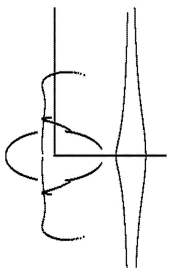
Figure 2.
q = 1, KG = 80, and DK = 120.
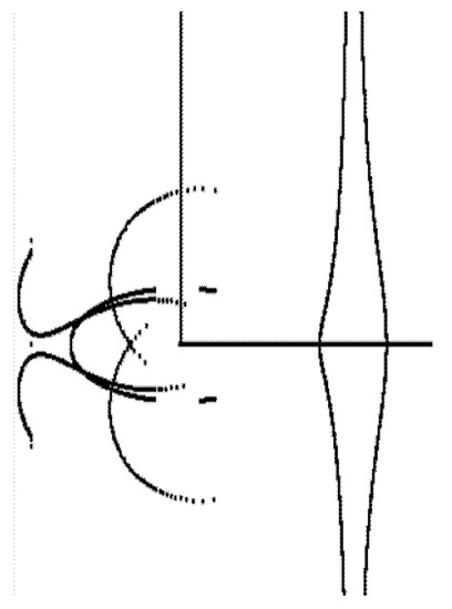
Figure 3.
q = 1, KG = 60, and DK = 200.
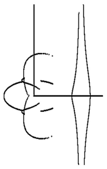
Figure 4.
q = 1, KG = 60, and DK = 130.
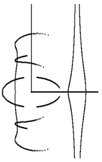
Figure 5.
q = 1, KG = 100, and DK = 140.
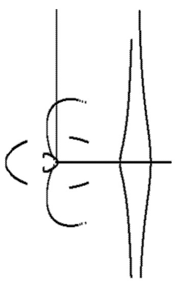
Figure 6.
q = 1, KG = 50, and DK = 120.
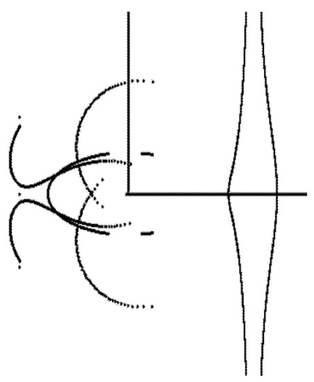
Figure 7.
q = 1, KG = 60, and DK = 140.
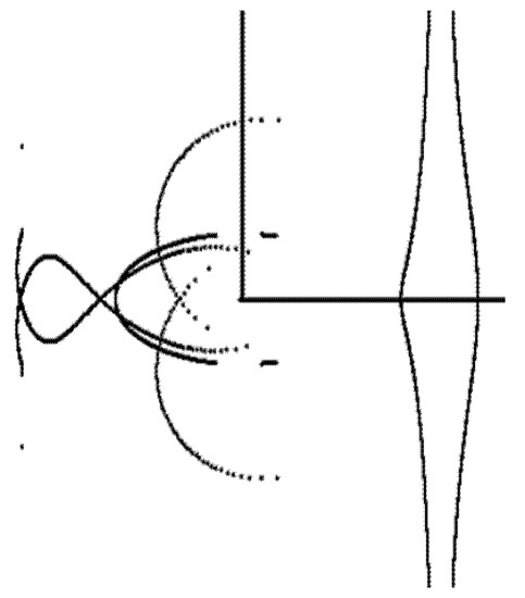
Figure 8.
q = 1, KG = 60, and DK = 220.
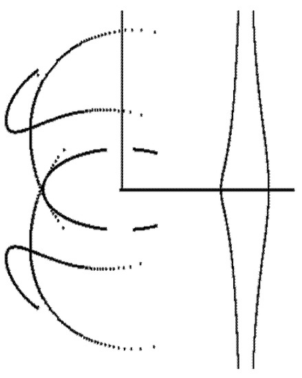
Figure 9.
q = 1, KG = 100, and DK = 200.
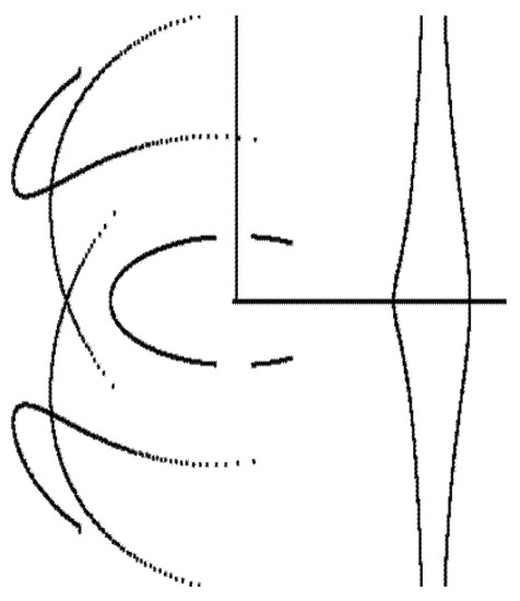
Figure 10.
q = 1, KG = 120, and DK = 220.
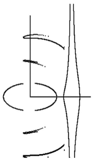
Figure 11.
q = 1, KG = 120, and DK = 120.
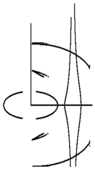
Figure 12.
q = 1, KG = 120, and DK = 100.
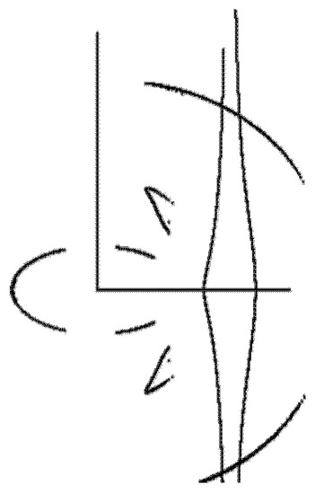
Figure 13.
q = 1, KG = 130, and DK = 65.
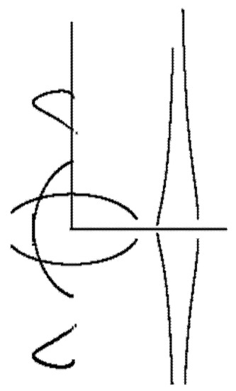
Figure 14.
q = 0.5, KG = 100, and DK = 140.
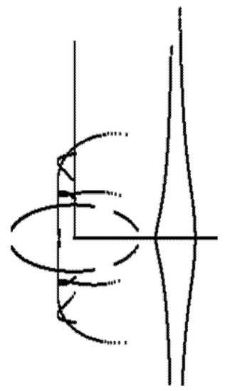
Figure 15.
q = 1.5, KG = 80, and DK = 120.
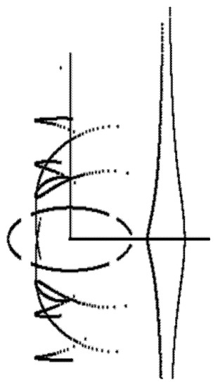
Figure 16.
q = 2, KG = 100, and DK = 140.
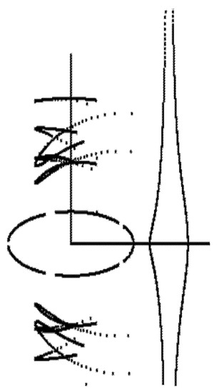
Figure 17.
q = 2.5, KG = 120, and DK = 140.
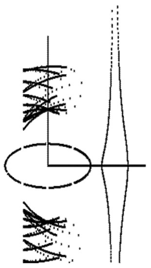
Figure 18.
q = 5, KG = 120, and DK = 140.
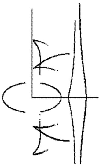
Figure 19.
q = −1, KG = 100, and DK = 100.
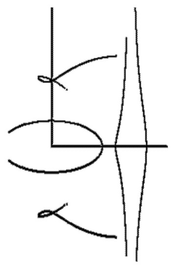
Figure 20.
q = −0.5, KG = 120, and DK = 120.
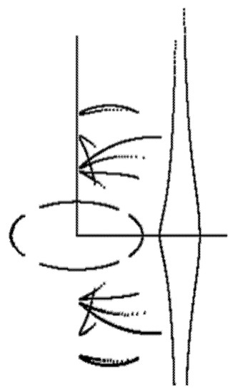
Figure 21.
q = −2, KG = 100, and DK = 100.
The curves were generated for the situation where the leading elements rotate either in the same direction (the q parameter has positive values, Figure 2, Figure 3, Figure 4, Figure 5, Figure 6, Figure 7, Figure 8, Figure 9, Figure 10, Figure 11, Figure 12, Figure 13, Figure 14, Figure 15, Figure 16, Figure 17 and Figure 18) or in the opposite one (the q parameter has negative values, Figure 19, Figure 20 and Figure 21).
Various cases were analyzed when the angular velocities of the two leading elements were equal (q = 1, Figure 2, Figure 3, Figure 4, Figure 5, Figure 6, Figure 7, Figure 8, Figure 9, Figure 10, Figure 11, Figure 12 and Figure 13) or different (q1, Figure 14, Figure 15, Figure 16, Figure 17, Figure 18, Figure 19, Figure 20 and Figure 21).
After analyzing these diagrams, taking into account their continuity and aesthetics, the mechanism that draws the curves in Figure 2 was chosen. The criterion of continuity and the open aspect of the geometry of the curve were essential for fulfilling the requirement of separation of the support plane into two half-planes to obtain free curved surfaces. The geometric modeling of the mechanism was done by taking into account its structure (the type of kinematic elements and joints) and its geometry (the dimensions of the elements, the constant angles, and the positions of the bases), imposing the initial angles of the two leading elements: ϕ = ψ = 75°.
For the analysis of the positions and the animation of the mechanism, the Altair program was run, considering the same angular velocity for the two leading elements. Figure 22a shows the plan view, and Figure 22b the axonometric one of the mechanism and the curves drawn by points D, G1, G2, and K.
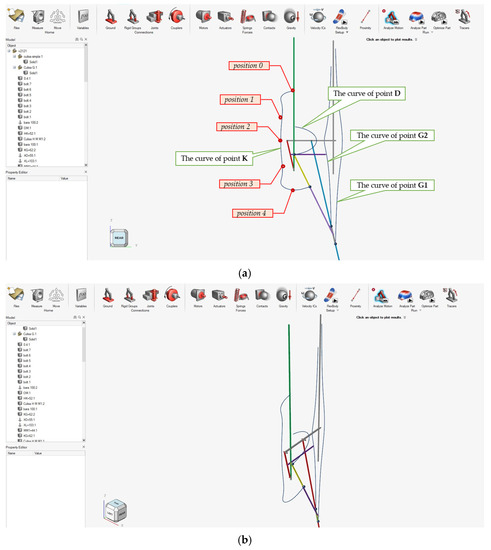
Figure 22.
The mechanism and the obtained curves: (a) plan view; (b) axonometric view.
Figure 23a shows the mechanism during operation in five successive positions, and Figure 23b highlights one of the critical positions, when elements no. 1, 6, 7, 9, and 10 are collinear.
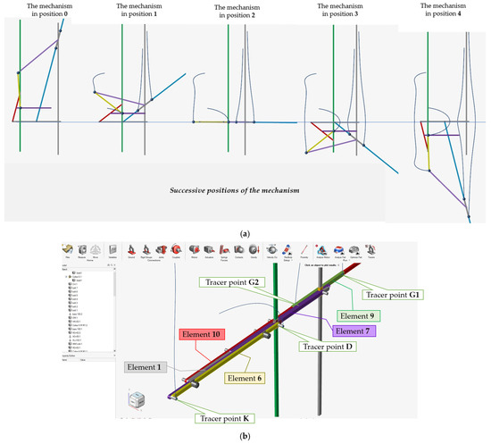
Figure 23.
The mechanism during operation: (a) in five successive positions and (b) in one critical position (no. 2).
3. Virtual Analysis of the Technological Process to Obtain Free Forms
The range of values for the angle of the leading elements during the operation of the mechanism is 75–283 degrees.
With the help of the Altair program, in Figure 22a, the trajectory of point K is drawn; The Export Locations option of the program allows to save a .csv file containing global x,y,z location data of the drawn curve points. The coordinates of the points of this curve located in the yOz plane are shown in Table 1, these being necessary for drawing it on the support plate.

Table 1.
The coordinates of the bending curve points.
The coordinates given by the Altair program in a .csv file (table type) were transferred to an AutoCAD script file to generate the symmetric curve from Figure 24, which was then imported into Inventor to draw the outline of the channel used for bending.
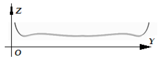
Figure 24.
The curve drawn by the mechanism.
The geometric modeling is completed by placing the curve on a plate support in the Inventor program, and the model is imported into the Altair program. The V-shaped channel is practiced along the curve and will be able to allow plate support deformation easily.
In order to simulate the technological process of the free-folded surface, an aluminum alloy was chosen for the material of the plate support; the material characteristics are given in Table 2.
Table 2.
The material characteristics.
It is known that the dimensions and shape of the support plate influence its deformation mode; for this reason, five variants have been proposed. The geometric shapes of the support plates have the dimensional characteristics given in Figure 25, Figure 26, Figure 27, Figure 28 and Figure 29. The model no. 1 has a rectangular shape, models no. 2 and no. 3 have two different fillet radii, model no. 4 has an external offset to the drawn curve, and model no. 5 has a trapezoidal shape, with one of the overall dimensions increased compared to model no. 1, keeping the second one constant.
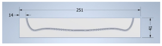
Figure 25.
The model no. 1.
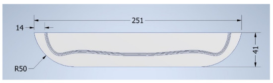
Figure 26.
The model no. 2.
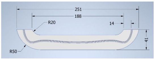
Figure 27.
The model no. 3.
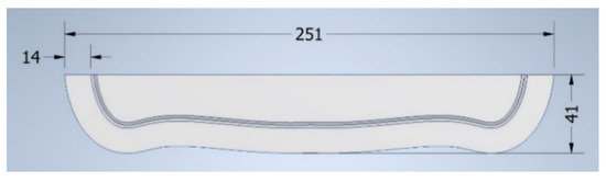
Figure 28.
The model no. 4.
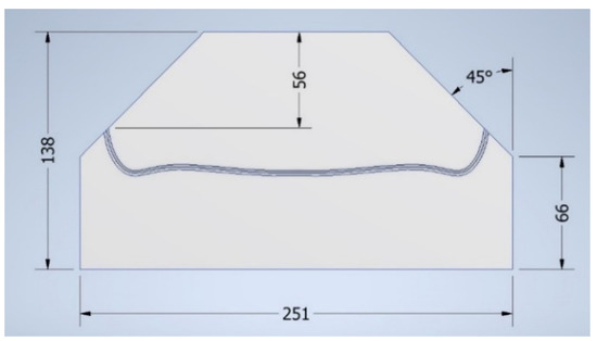
Figure 29.
The model no. 5.
Constraints were imposed by blocking the displacements of the curve points.
A normal pressure uniformly distributed on the edge of the plate equal to 25 MPa was applied for all the proposed variants. The pressure value was determined by simulations so that the material reaches the state of plastic deformation. The deformations (Figure 30a, Figure 31a, Figure 32a, Figure 33a and Figure 34a) and the equivalent von Mises stresses (Figure 30b, Figure 31b, Figure 32b, Figure 33b and Figure 34b were determined.
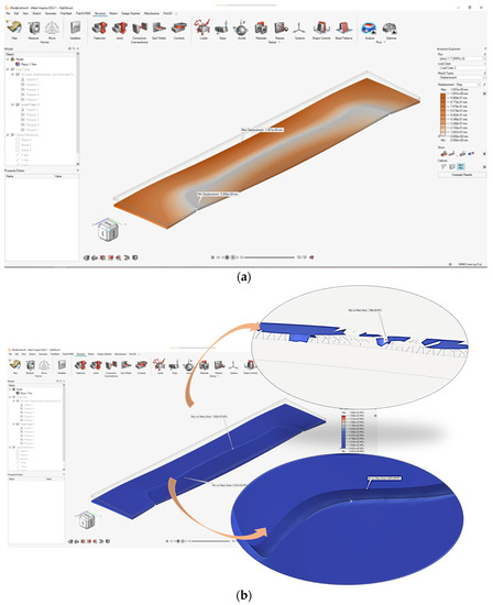
Figure 30.
The model no. 1: (a) deformations; (b) von Mises equivalent stresses.
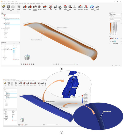
Figure 31.
The model no. 2: (a) deformations; (b) von Mises equivalent stresses.
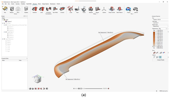
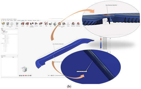
Figure 32.
The model no. 3: (a) deformations; (b) von Mises equivalent stresses.
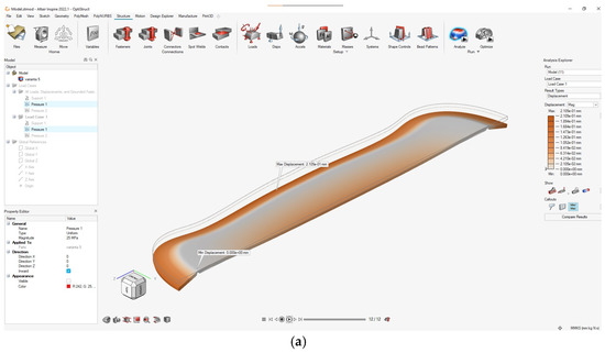
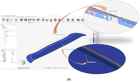
Figure 33.
The model no. 4: (a) deformations; (b) von Mises equivalent stresses.
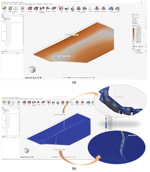
Figure 34.
The model no. 5: (a) deformations; (b) von Mises equivalent stresses.
4. Results and Discussions
The choices of the geometric shapes for all five proposed variants of the support plate were made starting from the condition that the curve separates the surface into two half-planes. This requirement facilitates the formation of spatial surfaces adjacent to the curve independently.
The results obtained from the simulations are highlighted in Table 3.
Table 3.
Results from the Altair program simulation.
In the analysis of the deformations, since we imposed as a constraint condition for the simulation of the technological process that the curve keeps its flatness, all the points located on it will have zero displacements measured in relation to the reference system. Due to the geometry of the curve, the maximum deformations are recorded in all cases in the outer half-plane of the curve (relative to its curvature). The highest value of 1771 mm (model 5, Figure 34a and Table 3) is recorded in the case when the distance related to the curve is the largest, the material of the plate being subjected to stretching.
The equivalent stresses were the result of stresses and strains acting during and after the folding process. The mechanical behavior of metallic materials is defined by stress-strain fields, which appear as a result of external stimuli/loads and are mediated by the microstructure–mechanical properties relationship [25,26].
From the analysis of the results, it can be seen that the maximum value of 2.958 × 10³ MPa for the von Mises equivalent stress is recorded on the surface opposite to the channel of model 3, the material subjected to bending stress exceeding the yield stress limit (Figure 32a and Table 3).
For all variants, the minimum equivalent stresses were observed in the area of the delimiting edge of the channel in the inner half-plane of the curvature due to the limited constraint compared to that of the fixed edge. The minimum value of 3.020 × 100 MPa for von Mises equivalent stress was recorded in model 2 (Figure 31 and Table 3).
5. Conclusions
In this study, we started by drawing a curve with the help of a mechanism. From the analysis of a set of curves obtained by varying the parameters of the mechanism, one of the curves without discontinuities and with an aesthetic shape was chosen to obtain free-folded surfaces.
With the Altair program, a simulation of one technological process was made to obtain freeforms that fold according to the chosen curve. The process is based on pressing with a uniformly distributed force on the edge of a support plate, and the simulation results were analyzed, establishing the most stressed areas.
Additionally, another variant of the study is proposed for future research in which the technological process of free pressing will be simulated; the punch will be modeled starting from the geometry of the same curve.
Author Contributions
Conceptualization, A.D., I.P. and S.-M.C.; methodology, A.D., S.-M.C. and D.-L.P.; software, I.P., A.C. and V.C.; validation, A.D., S.-M.C., A.C. and V.C.; formal analysis, A.D.; investigation, A.D. and S.-M.C.; resources, A.D., A.C. and V.C.; data curation, A.D., A.C. and V.C.; writing—original draft preparation, A.D. and S.-M.C.; writing—review and editing, A.D.; visualization, I.P.; supervision, A.D.; project administration, A.D.; and funding acquisition, A.D. All authors have read and agreed to the published version of the manuscript.
Funding
This research was funded by the University of Craiova, 13 A.I. Cuza Street, RO-200585, Craiova, Romania.
Institutional Review Board Statement
Not applicable.
Informed Consent Statement
Not applicable.
Data Availability Statement
Not applicable.
Conflicts of Interest
The authors declare no conflict of interest.
References
- Capone, M.; Lanzara, E. Kerf bending: Ruled double curved surfaces manufacturing. In Proceedings of the 22th Conference of the Iberoamerican Society of Digital Graphics, São Carlos, Brazil, 7–9 November 2018. [Google Scholar]
- Rabinovich, M.; Hoffmann, T.; Sorkine-Hornung, O. Modeling curved folding with freeform deformations. ACM Trans. Graph. 2019, 38, 1–12. [Google Scholar] [CrossRef]
- Demaine, E.; Demaine, M.; Koschitz, D.; Tachi, T. Curved Crease Folding a Review on Art, Design and Mathematics. In Proceedings of the 35th Annual Symposium of IABSE/52nd Annual Symposium of IASS/6th International Conference on Space Structures: Taller, Longer, Lighter—Meeting Growing Demand with Limited Resources, London, UK, 20–23 September 2011. [Google Scholar]
- Raducanu, D.; Cojocaru, V.; Raducanu, V.; Nocivin, A.; Serban, N.; Cinca, I.; Cojocaru, E.; Moldovan, L.; Trisca-Rusu, C.; Balkan, I. Design and Optimization of a Curved-Crease-Folding Process Applied to a Light Metallic Structure. Processes 2021, 9, 1110. [Google Scholar] [CrossRef]
- Bacinoglu, S.Z.; Piskorec, L.; Kotnik, T. CURVED.IT: A design tool to integrate making with curved folding into digital design process. A/Z ITU J. Fac. Arch. 2019, 16, 11–27. [Google Scholar] [CrossRef]
- Foschi, R. Algorithmic Modelling of Folded Surfaces. Analysis and Design of Folded Surfaces in Architecture and Manufacturing. Ph.D. Thesis, Alma Mater Studiorum Università di Bologna, Bologna, Italy, 2019. [Google Scholar]
- Chen, Y.; Yan, J.; Feng, J. Geometric and Kinematic Analyses and Novel Characteristics of Origami-Inspired Structures. Symmetry 2019, 11, 1101. [Google Scholar] [CrossRef]
- Available online: https://asm.matweb.com/search/SpecificMaterial.asp?bassnum=ma6061t6 (accessed on 10 June 2022).
- Stachel, H. Remarks on Miura-ori, a Japanese folding method, Acta Technica Napocensis. In Proceedings of the International Conference on Engineering Graphics and Design, Cluj Napoca, Romania, 12–13 June 2009. [Google Scholar]
- Chen, Y.; Guest, S.D.; Fowler, P.; Feng, J. Two-Orbit Switch-Pitch Structures. J. Int. Assoc. Shell Spat. Struct. 2012, 53, 157–162. [Google Scholar]
- Stachel, H. Two Examples of Solids Constructed from Given Developments. J. Geom. Graph. 2016, 20, 225–241. [Google Scholar]
- Mundilova, K. On mathematical folding of curved crease origami: Sliding developables and parametrizations of folds into cylinders and cones. Comput. Des. 2019, 115, 34–41. [Google Scholar] [CrossRef]
- Dias, M.A.; Dudte, L.H.; Mahadevan, L.; Santangelo, C.D. Geometric Mechanics of Curved Crease Origami. Phys. Rev. Lett. 2012, 109, 114301. [Google Scholar] [CrossRef] [PubMed]
- Lee, T.-U.; You, Z.; Gattas, J.M. Elastica surface generation of curved-crease origami. Int. J. Solids Struct. 2018, 136-137, 13–27. [Google Scholar] [CrossRef]
- Gattas, J.; You, Z. The behaviour of curved-crease foldcores under low-velocity impact loads. Int. J. Solids Struct. 2015, 53, 80–91. [Google Scholar] [CrossRef]
- Verma, S.; Epps, G. Curved Folding: Design to Fabrication; Adaptive Architecture: London, UK, 2013. [Google Scholar]
- Chen, Y.; Lu, C.; Yan, J.; Feng, J.; Sareh, P. Intelligent computational design of scalene-faceted flat-foldable tessellations. J. Comput. Des. Eng. 2022, 9, 1765–1774. [Google Scholar] [CrossRef]
- Turrin, M.; von Buelow, P.; Stouffs, R. Design explorations of performance driven geometry in architectural design using parametric modeling and genetic algorithms. Adv. Eng. Inform. 2011, 25, 656–675. [Google Scholar] [CrossRef]
- Hrones, J.; Nelson, G. Analysis of the Four-Bar Linkage: Its Application to the Synthesis of Mechanisms; The MIT Press: London, UK, 1951. [Google Scholar]
- Chung, W.-Y. The characteristics of a coupler curve. Mech. Mach. Theory 2005, 40, 1099–1106. [Google Scholar] [CrossRef]
- Popescu, I.; Sass, L. Mecanisme Generatoare de Curbe; Editura Scrisul Românesc: Craiova, Romania, 2001. [Google Scholar]
- Popescu, I. Noi Mecanisme Generatoare de Curbe; Editura Sitech: Craiova, Romania, 2014. [Google Scholar]
- Popescu, I.; Luca, L.; Cherciu, M.; Marghitu, D. Mechanisms for Generating Mathematical Curves; Springer: Berlin/Heidelberg, Germany, 2020. [Google Scholar] [CrossRef]
- Structuri Spațiale Proiectate Pentru Structuri Complexe Ușoare Procesate prin Curved Crease Folding [CCF–Surf] (Spatial Surfaces Designed for Complex, Light Weight Structures Processed by Curved Crease Folding), Project Manager Raducanu D. Project No. 468PED/23.10.2020–UEFISCDI. Available online: http://www.mdef.pub.ro/research/CCF-Surf/ro/index.html (accessed on 20 September 2022).
- Cojocaru, V.D.; Raducanu, D.; Gloriant, T.; Gordin, D.M.; Cinca, I. Effects of cold-rolling deformation on texture evolution and mechanical properties of Ti-29Nb-9Ta-10Zr alloy. Mater. Sci. Eng. A 2013, 586, 1–10. [Google Scholar] [CrossRef]
- Chahardoli, S.; Nia, A.A. Investigation of mechanical behavior of energy absorbers in expansion and folding modes under axial quasi-static loading in both experimental and numerical methods. Thin-Walled Struct. 2017, 120, 319–332. [Google Scholar] [CrossRef]


Publisher’s Note: MDPI stays neutral with regard to jurisdictional claims in published maps and institutional affiliations. |
© 2022 by the authors. Licensee MDPI, Basel, Switzerland. This article is an open access article distributed under the terms and conditions of the Creative Commons Attribution (CC BY) license (https://creativecommons.org/licenses/by/4.0/).