Review

A Novel Carbon Dioxide Phase Transition Rock Breaking Technology: Theory and Application of Non-Explosive Blasting

1
Key Laboratory of Deep Coal Resource, Ministry of Education of China, China University of Mining & Technology, Xuzhou 221116, China
2
School of Mines, China University of Mining & Technology, Xuzhou 221116, China
*
Author to whom correspondence should be addressed.
Processes 2022, 10(11), 2434; https://doi.org/10.3390/pr10112434
Submission received: 7 October 2022 / Revised: 7 November 2022 / Accepted: 14 November 2022 / Published: 17 November 2022

Abstract

:
As a non-explosive low-disturbance rock breaking technology, carbon dioxide phase transition blasting (CDPTB) is widely used in rock breaking projects such as pressure relief and permeability enhancement in coal mines, open-pit mining, road subgrade excavation, foundation pit excavation, etc. In this paper, the principle and equipment of CDPTB are systematically analyzed, and the characteristics of a reusable fracturing tube and disposable fracturing tube are determined. Different energy calculation methods are analyzed to determine the magnitude or equivalent explosive equivalent of CDPTB. According to the characteristics of impact stress wave and high-pressure gas, the cracking mechanism of CDPTB is proposed. Under the action of medium-impact stress, rock mass will produce multi-point cracking, and high-pressure gas will produce a gas wedge effect in the initial fracture, which determines the comprehensive action path of the stress wave and high-pressure gas. In terms of fracture characteristics, the fractal method is used to evaluate the macroscopic crack and fragment, microscopic fracture and pore characteristics. In terms of vibration characteristics, the attenuation law of CDPTB vibration with distance is statistically analyzed, and the Hilbert–Huang transform method is used to analyze the time–frequency characteristics of CDPTB. This rock breaking technology can be widely used in different projects, and the existing problems and future challenges are put forward.

1. Introduction

Rock breaking technology is widely used in coal, metallurgy, petroleum, natural gas, hydropower, transportation and other industrial projects. Explosive blasting is the most basic and common means of breaking rock. When an explosive explodes, it releases a lot of heat and produces high-temperature and high-pressure gas, which destroys, throws and compresses the surrounding materials. Due to the violent chemical changes in the explosion process, the most common safety concerns and undesirable side effects include ground vibrations, flyrock, noise, premature explosion and air/dust pollution [1]. Moreover, with the gradual deepening of environmental protection, labor protection policies, and requirements for safe and efficient production, the use conditions of explosives are more and more strictly restricted under certain engineering scopes or conditions. For example, in China the coal mine safety regulations prohibit the use of explosives in the mining affected area. In addition, explosive blasting is also prohibited in the surrounding areas of some urban residential areas, adjacent to traffic trunk lines, urban tunnels and subways, and subgrade rock excavation [2,3]. Using non-explosive blasting technology to replace traditional blasting is required for construction safety, environmental protection and actual production, which has a good development prospect. Significant progress has been made in non-explosive rock breaking techniques such as thermal, chemical, hydraulic and electrohydrodynamic, which hold considerable promise for being environmentally friendly as well as being cost-effective [4]. Among them, the carbon dioxide phase transition blasting (CDPTB) technology has the characteristics of good safety, low blasting vibration, low environmental pollution, controllable energy and simple operation [5], and has been widely used in rock breaking projects such as pressure relief and permeability enhancement in coal mines, open-pit mining, road subgrade excavation, foundation pit excavation, etc. [6,7], which has played an important role in promoting the progress of blasting technology and improving the intrinsic safety of blasting and the level of social public safety.
CDPTB is a non-explosive low-disturbance rock breaking technology. The carbon dioxide is enclosed in a special blasting tube and is rapidly transformed into a gaseous state by high heat excitation, resulting in a powerful expansion energy and a rapid release of high-pressure gas to create a tensile stress field in the rock, so as to achieve the effect of fracturing the rock mass. This technology originated from Cardox technology in Europe and America in 1914, and was first applied to the mining of highly gassy coal seams. It was widely used in the United States, Britain and Canada, and was praised as the most famous technical invention in the field of coal mines by the United States Bureau of Mines [8,9]. According to statistics, in the 1940s, CDPTB produced 25% of the coal output of underground mines in the United States, with annual blasting volumes once reaching as high as 2.8 million blasts [10]. With the continuous development of mechanized coal mining technology and related integrated mining equipment, the technology has been gradually withdrawn from the coal mining industry and gradually shifted to urban earth and rock blasting and cement industry to clear blockages, etc. At this stage, the technology is applied in more than 100 countries in total [11]. CDPTB technology was introduced to China in the 1990s, and coal mining trials were conducted at the beginning of the 21st century in coal mining faces of high-gas mines in China. The feasibility of applying this technology to mine gas control is found through relevant practice [12]. Since 2012, this technology has been widely applied to mine methane control in different mines [11]. After 2014, it was expanded from underground mines to open-pit mines, and was applied to open-pit rock blasting projects such as mines, roads and foundation pits.
At present, although CDPTB technology has been widely used, there is a lack of theoretical research and relevant specifications, resulting in certain difficulties in large-scale promotion and application. In order to promote the application and expansion of CDPTB, this paper systematically analyses the principles of CDPTB and its equipment, and determines the method of calculating blasting energy, with reference to the current situation of CDPTB research. Based on the characteristics of CDPTB impact stress waves and high-pressure gas, the fracture mechanism of CDPTB is proposed, and the characteristics of rock breaking under the combined effect of medium-impact stress and high-pressure gas are revealed. In terms of fracture characteristics, the fractal method is used to evaluate the macroscopic crack and fragment, microscopic fracture and pore characteristics. In terms of vibration characteristics, the attenuation law of CDPTB vibration with distance is statistically analyzed, and the Hilbert–Huang transform method is used to analyze the time–frequency characteristics of CDPTB. This rock breaking technology can be widely used in different projects, and the existing problems and future challenges are put forward.

2. Carbon Dioxide Phase Transition Blasting Technology

2.1. Principle of Carbon Dioxide Phase Transition Blasting

CDPTB is a non-explosive blasting technology, which uses the rapid expansion characteristics of liquid carbon dioxide during phase change to apply energy to the surrounding medium to achieve the effect of blasting. The whole process is a physical change and is safe because it does not involve high temperatures, open flames or harmful gases as in traditional blasting. CDPTB uses a blasting cylinder, which consists of a filling head, a heating element, a storage tube, a shear rupture disc and a releasing head. The principle of CDPTB is shown in Figure 1. Liquid carbon dioxide is poured into the storage tube using the filling equipment. When an electric current is passed through the heating element, it heats the carbon dioxide gas in the storage tube. With the increase in temperature, carbon dioxide begins to vaporize rapidly, and its volume expands more than 660 times, and the pressure in the liquid storage pipe increases sharply. When the pressure exceeds the strength of the shear rupture disc, the high-pressure carbon dioxide ruptures the disc and is ejected through the releasing head. The high-pressure gas acts directly in the surrounding solid medium, causing the medium to destroy and invade its cracks, producing a wider range of cracks, and producing less vibration and sound. The storage tube can be recycled at the end of the blasting task to complete the CO2 filling and blasting process again. Depending on the parameters of the blast, blasting tubes of different lengths, diameters and sizes can be selected to meet the practical requirements of the site.
According to the principle of CDPTB, it is clear that this technology has the following characteristics.
(1) Good safety. All of the carbon dioxide is enclosed in a fixed container, and its initiation method is to activate the heating element by electricity, which does not produce an open flame to cause gas explosions and other accidents. At the same time, ordinary vibration and impact cannot cause explosion. It has high safety in the storage, transportation, use and management of blasting equipment.
(2) Environmentally friendly. Compared with the traditional explosive blasting, CDPTB will not produce toxic and harmful gas and smoke during the whole process. Carbon dioxide can effectively absorb the nearby temperature and reduce the ambient temperature while expanding to do work.
(3) Good controllability. The explosion pressure of carbon dioxide phase change is determined by the strength of the shear rupture disc. The explosion energy can be reasonably controlled by changing the specification of the disc. At the same time, the high-pressure carbon dioxide generated after blasting is applied to the surrounding media through the releasing head. The main blasting direction of CDPTB can be controlled by the number of holes on the releasing head. Precise control of blasting energy and direction can be achieved according to site requirements.

2.2. Carbon Dioxide Phase Transition Blasting Equipment

The storage tube is the main device for phase change blasting and can be divided into reusable fracturing tubes and disposable fracturing tubes, depending on the form of the storage tube and the form of gas release (as shown in Figure 2). The reusable fracturing tube uses a steel tube with a thicker wall (10 mm or more) as the storage tube, and the high-pressure gas inside the tube is released through a shear rupture disc at the bottom of the tube. The disposable fracturing tube has a thin wall (1.5 mm) and is reinforced by a tube plate process. The welded seam on the side of the tube is a carbon dioxide release channel [13], where the carbon dioxide gas is released from the side of the tube rather than from the bottom of the tube. This gas release method also helps to eliminate the “flying tube” problem, and makes the gas expansion pressure more evenly used on the blast hole wall. Although the two forms are different in structure, the principles of operation are similar [3].
The traditional CDPTB mostly uses the reusable fracturing tube, which can be divided into a filling head, a heating element, a storage tube, a shear rupture disc and a releasing head. The structure is shown in Figure 3. The filling head contains a liquid filling valve and an ignition head, the liquid filling valve is used to re-fill the CO2 after each blast and the ignition head electrode is connected to the external wire to heat the heat pipe. The heating element is filled with chemical substances. During blasting, the ignition head electrode is energized to produce heat that causes the chemicals to react rapidly, releasing a large amount of heat and causing the carbon dioxide to vaporize rapidly. The shear rupture disc is mainly used to control the blasting pressure during CDPTB. Once the pressure of the vaporized carbon dioxide exceeds the strength of the bursting disc, the bursting disc will be damaged and the gas will be released. Generally, a shear type bursting disc is used, which is simple in structure and easy to install. To ensure the sealing effect, a gasket is added between the disc and the main body of the storage tube to play a sealing role. The releasing head is a carbon dioxide release channel with venting holes for controlling the gas release method. Depending on the requirements, the releasing head can be set up with different shapes of venting holes. The storage tube is the main body of the CDPTB device, which is used to contain high-pressure carbon dioxide.

2.3. Energy Characteristics of Carbon Dioxide Phase Transition Blasting

The energy density of CDPTB is less than that of a dense chemical explosive. Accurate calculations of CDPTB energy are essential for assessment of blasting effectiveness and quantification of blasting capacity.
The calculation of CDPTB energy includes using compressed gas and water vapor containers to calculate blasting energy, using jet velocity to calculate blasting energy, using the volume of gaseous explosion products to calculate blasting energy, using blasting vibration equivalent explosion energy and using a real state equation to calculate blasting energy.
(1) Calculation formula of explosion energy by using compressed gas and water vapor containers [14]:
  E = P 1 V K 4 1 P 2 P 1 K 1 K ,
where: E is the gas explosion energy, kJ; P1 is the absolute pressure of the gas in the reservoir, MPa; P2 is the absolute pressure of the external environment, taken as 0.101325 MPa; V is the volume of the reservoir, m³; K is the adiabatic index of CO2, taken as 1.295.
This formula is derived from the ideal gas equation of state and is applicable to medium- and low-pressure conditions. When CO2 is near the critical point or the pressure is large, the error of the ideal gas equation of state is large, and the method does not consider the part of explosion energy converted into a shock wave, so the calculation result is often small.
(2) Calculation formula of explosion energy by using jet velocity [10]:
E = 1 2 v 2 + k k 1 p 2 ρ p 2 p 1 1 k ,
where: v is the outlet velocity of the bursting disc, m/s, ρ is the density in the container.
The formula mainly determines the value of explosion energy by the speed, while the pressure has little influence on the explosion energy. Moreover, the formula does not consider the influence of volume and mass on the explosion energy, so there is a large error [15].
(3) Calculation formula of explosion energy by using the volume of gaseous explosion products [16].
The volume of gaseous explosion products is a fundamental property of explosives that directly determines their fracturing ability. The volume of high-pressure gas produced by the phase change of liquid carbon dioxide is the basic characteristic of this technology, which is equivalent to the volume of gaseous explosive explosion products. The analysis and comparison of gas volume produced by an explosive explosion and CDPTB is of great significance to the calculation and verification of a CDPTB equivalent.
E = Q W T N T Q T N T ,
where: Q is the volume of gaseous explosion products of CDPTB, QTNT is the volume of gaseous explosion products of TNT explosive and WTNT is the explosive energy of unit TNT explosive.
In the standard state, 509 L high-pressure gas is generated after 1 kg liquid carbon dioxide phase change, and 740 L explosive gas is generated after 1 kg TNT explosive explosion. From the calculation of the phase change equivalent of liquid carbon dioxide, it is known that 1 kg of liquid carbon dioxide phase change equivalent is 397 g of TNT explosive [16].
(4) Calculation formula of explosion energy by using blasting vibration [17].
As the external manifestation of the explosion energy, the vibration can also approximately reflect the total energy of the explosion source. A comparative analysis of the shock wave formed by CDPTB and the shock wave formed by the explosion of a certain amount of TNT is used to determine a reasonable calculation method from the energy point of view using the wavelet analysis principle. The phase change equivalent of 1 kg liquid carbon dioxide is calculated to be 430 g TNT explosive through the analysis of the RMS amplitude of explosive vibration wave. From the perspective of spectrum energy analysis, the equivalent of phase change of 1 kg liquid carbon dioxide is 380 g TNT explosive.
E = R M S R M S T N T W T N T ,
where RMS is the root mean square amplitude of the of explosive vibration wave.
(5) Calculation formula of explosion energy by using a real state equation.
The Span and Wagner equation of state is an empirical formula obtained by reviewing a large amount of previous useful data on the thermodynamic characteristics of CO2. It covers the calculation of the thermodynamic characteristics of CO2 fluid from the three-phase point temperature of 1100 k within the pressure range of 0~800 MPa, with high accuracy.
The equation of state is the basic equation expressed by the Helmholtz free energy formula, including two independent variables, density ρ and temperature T. All thermodynamic properties can be obtained by the derivation of this basic equation.
The Span and Wagner equation of state equation is given by
  E = 1 2 p d V ,
where: V is the volume of the material expansion body, and p is the corresponding pressure.
According to the theory of explosion thermodynamics, the increase in the system Helmholtz free energy reflects the accumulation of energy and the magnitude of the system explosion energy. The explosion energy equation can be expressed as follows.
  E = 1 2 p d V A = A 1 A 2 = R 1 T 1 2 T 2 ,
where the subscript “1” represents the state at the peak temperature point in the tube, and the subscript “2” represents the state when the high-pressure gas is released to the atmosphere.
The magnitude of the blast energy is approximately equal to the reduction in the Helmholtz free energy of the system. Therefore, it is only necessary to measure the density ρ1 and temperature T1 of the CO2 in the blast tube before the blast, and the energy of the phase change blast can be calculated by combining Equations (4) and (6).
The different CDPTB energies are calculated as shown in Table 1.
There are many factors affecting CDPTB, and the models and standards of different manufacturers are not uniform. The theoretical calculation is only for reference. The statistical distribution of blasting energy under different CDPTB modes is shown in Figure 4 [18,19,20,21,22,23,24,25]. Due to the differences in standards and methods, the CDPTB energy values are different, but the overall distribution is normal. The single tube blasting energy is concentrated between 500 and 1000 KJ, and some of the energy values are higher, around 2500 KJ. After the statistics of different phase change blasting energies, it can be obtained that the average value of single tube energy is 1018.3 KJ, and the median value is 904 KJ. The average value of phase change blasting energy per unit mass of carbon dioxide is 825.5 KJ, and the median value is 618.3 KJ.

3. Fracture Mechanism of Carbon Dioxide Phase Transition Blasting

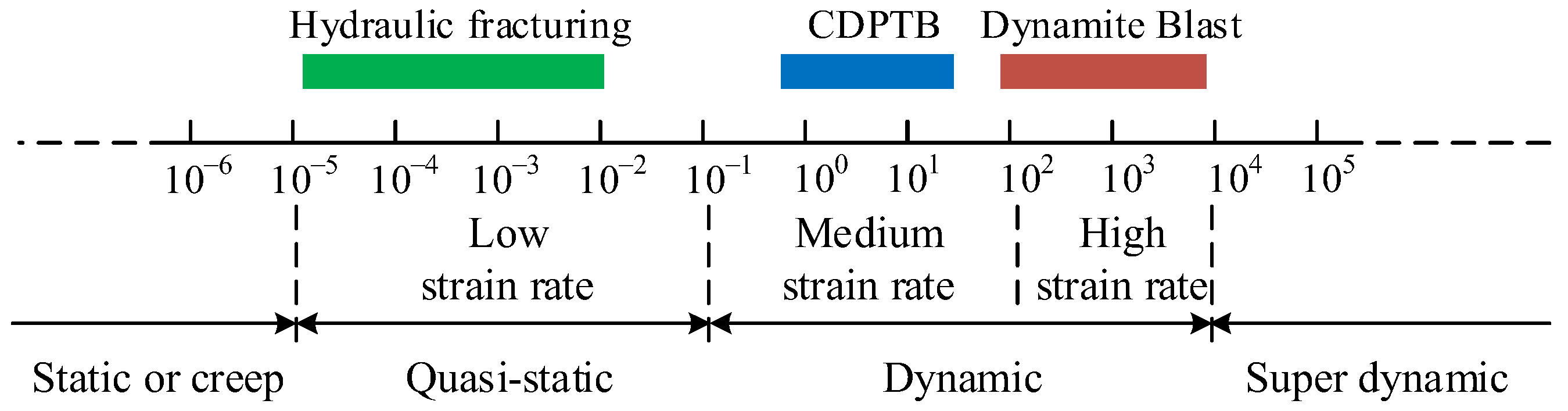
3.1. CDPTB Stress Wave Characteristics

The impact stress peak value and impact rate produced by different fracturing methods lead to different dynamic loads on the surrounding media. However, coal and rock materials have significant strain dependence. When the strain rate increases, the strength and hardening index of the materials will also increase. According to the different magnitudes of strain rate, the loaded strain rate is divided into static or creep (<10−5 s−1), quasi-static or low strain rate (10−5 s−1~10−1 s−1), dynamic (10−5 s−1~10−1 s−1) (divided into medium strain rate (10−1 s−1~102 s−1) and high strain rate (102 s−1~104 s−1)) and super dynamic (>104 s−1) [26,27]. As shown in Figure 5, the commonly used rock breaking methods are in the quasi-static or dynamic stage.
The traditional blasting method is that the explosive produces rapid and violent chemical changes, and the high-energy and high-speed detonation wave acts on the surrounding medium. The action energy is large, the detonation pressure can reach 10 GPa, the detonation speed is 3000~4000 m/s [11], the propagation speed is fast and the action time is short. Compared with blasting, CDPTB is a physical change that uses the expansion energy generated by the phase change of carbon dioxide. Its stress wave propagation speed is small (only about 1/10 of blasting), and the peak impact stress is much smaller than blasting. Hydraulic fracturing uses the action of high-pressure water in the borehole to pressure the medium, which has a longer duration of action and lower pressure. It can be regarded as a quasi-static process. The pressure characteristics of the different fracturing methods are shown in Table 2, and their pressure time history curves are shown in Figure 6 [28,29]. Based on the different impact stress characteristics and the dynamic strain rate range they are in, blasting fracturing, CDPTB fracturing and hydraulic fracturing are identified as high-stress rapid-impact, medium-impact and quasi-static impact, respectively.

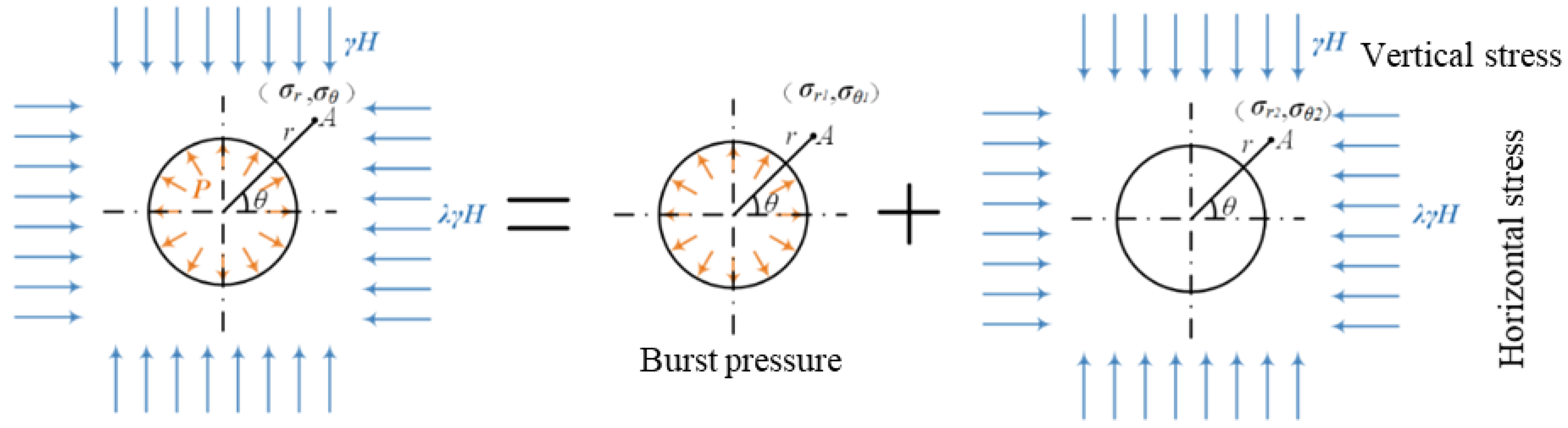
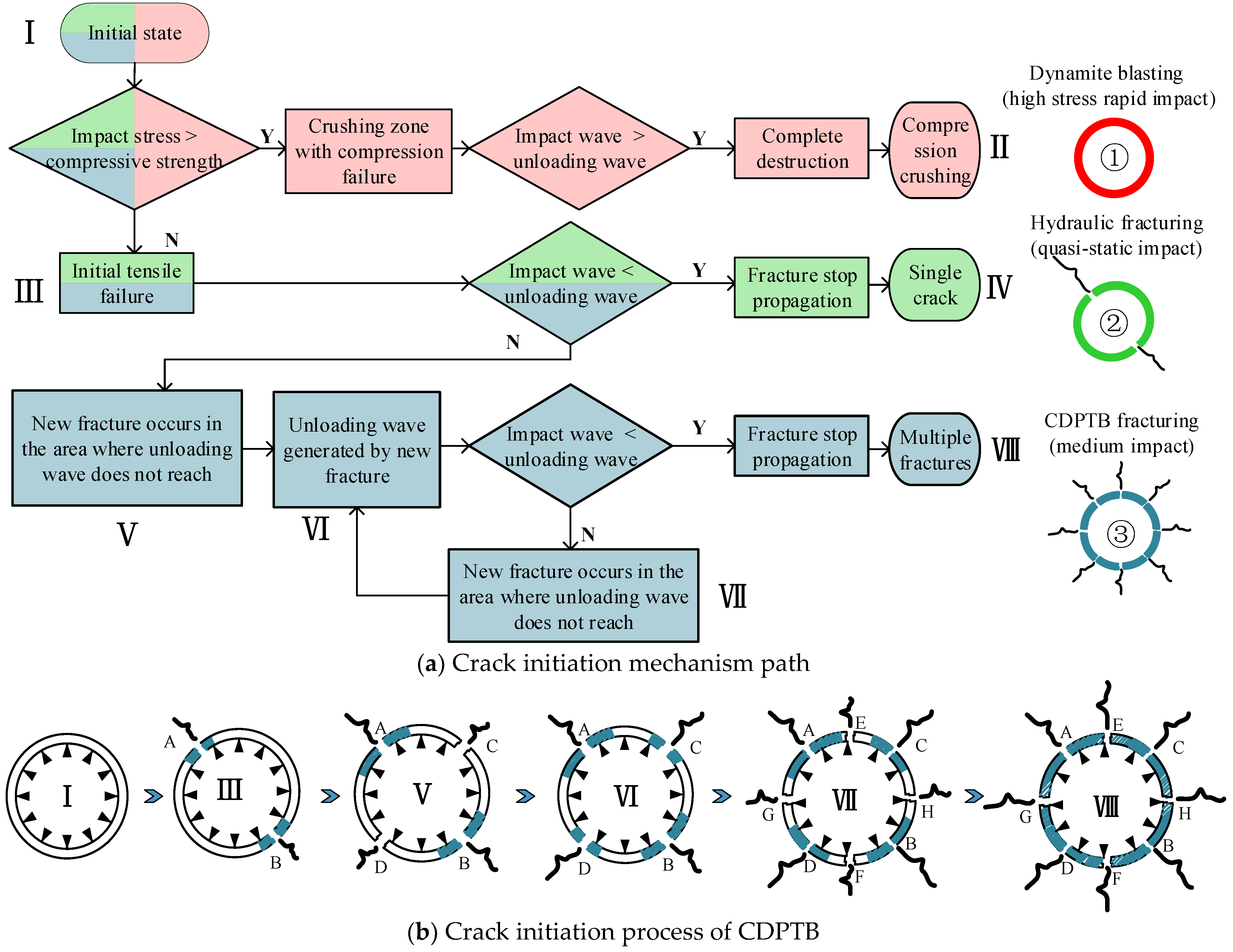
3.2. Mechanism of Fracture Initiation by Impact Stress Waves

The medium around the fracturing borehole is subjected to the external original in situ stress and the impact pressure P inside the borehole. As shown in Figure 7, the stress of the medium around the borehole can be obtained by superposition of the two stress characteristics [30].
σ r = R 2 r 2 P + γ H 2 1 + λ 1 R 2 r 2 γ H 2 1 λ 1 4 R 2 r 2 + 3 R 4 r 4 cos 2 θ σ θ = R 2 r 2 P γ H 2 1 + λ 1 + R 2 r 2 γ H 2 1 λ 1 + 3 R 4 r 4 cos 2 θ τ r θ = γ H 2 1 λ 1 + 2 R 2 r 2 3 R 4 r 4 cos 2 θ ,
where: σr is the radial stress, Pa; σθ is the tangential stress, Pa; τ is the shear stress, Pa; θ is the horizontal angle of the point, °; λ is the horizontal lateral pressure coefficient; H is the burial depth of rock mass; γ is the average unit weight of rock stratum, N/m3; R is the radius of the crack hole, m; P is the impact pressure, Pa; r is the distance from the point to the center of the borehole, m.
The stress characteristics around the borehole under hydrostatic pressure are plotted in Figure 8 according to Equation (7). The radial stresses generated by the impact stress and the ground stress have the same direction to play a superposition role. The medium around the fracture hole bears a large compressive stress. The tangential stress produced by impact stress and in situ stress acts on the contrary to weaken them. However, due to the large impact stress value and rapid attenuation, the tensile stress is applied to the place near the fracture. With the increase in the distance, the tensile stress value gradually decreases and gradually converts to the compressive stress.
When the blasting hole is at the limit of the lateral pressure coefficient of 0, the blasting hole is only subjected to the compressive stress in the vertical direction, but not the force in the horizontal direction. The shear stress as shown in Figure 9c is generated in the direction of 45° above the borehole.
Under the combined action of the initial in situ stress and the impact load of CDPTB, the radial compressive stress and the tangential tensile stress are formed around the blasting borehole. The initial stress of the rock stratum has no effect on the radial compressive stress at the boundary, but plays a part in attenuating the tangential tensile stress at the boundary. However, because the stresses generated by CDPTB are numerically larger than the initial stresses, the tangential tensile stresses are mainly present around the blasting borehole. The tensile strength of coal or rock mass is far less than the compressive strength. The coal or rock mass around the borehole is subject to tangential tension. When the stress exceeds its tensile strength, the coal and rock mass will produce an initial fracture.
When the material is subjected to drastic changes in impact loading, the dynamic changes in the material are often accompanied by multiple damage generation because the time required for the material damage evolution process is comparable to the loading time and the stress wave propagation time [31]. The medium around the borehole is subjected to radial compressive stress and tangential tensile stress. When the stress exceeds its strength, a fracture occurs around the borehole. According to Mott theory [32], after the fracture is generated, an unloading wave will be generated around the fracture and propagate to the surroundings. The propagation of the unloading wave can effectively release the stress. In other words, even if the area where the unloading wave propagates is affected by the impact stress, the unloading will occur, and no new fracture will occur. The fracture can only occur in the area not affected by the unloading wave.
The propagation velocity of the unloading wave in CDPTB is related to the properties and motion parameters of the material itself. For the same material, the characteristic of crack initiation around the borehole under different impact characteristics is shown in Figure 10. According to the initiation mechanism and final state of impact fracture, the damage caused by different impacts can be divided into three different paths: ① high-stress rapid impact (I → II); ② quasi-static action (Ⅰ → Ⅲ → Ⅳ); ③ medium impact (I → III → V → VI → VII → VIII).
① The core of different fracture forms is the difference of shock wave propagation rate and stress peak. When the impact stress is large and the rate is fast, the stress directly exceeds its compressive strength, and the coal body is compressed and destroyed. At the same time, the impact rate is fast, and the coal rock body is completely destroyed before the unloading wave is fully formed. The unloading wave cannot form an effective unloading effect (I → II), and a crushing fracture zone is formed around the borehole.
② As the peak value of impact stress decreases, the dynamic compressive strength of coal or rock mass cannot be reached. However, when the tangential stress is greater than the tensile strength, the coal body will produce an initial fracture (A, B) under the action of the tangential tensile stress formed by the impact stress. After the initial fracture occurs, the unloading wave propagates from the fracture to the surroundings (Ⅰ → Ⅲ). If the impact stress rate is slow, the unloading wave is transmitted to the whole area, the coal body is effectively unloaded and no new fracture will occur under the action of the internal stress in the borehole, and finally a single fracture (I → III → IV) will be formed.
③ If the impact velocity is between the above two conditions, after the initial fracture (I → III) occurs, the impact wave will continue to act on the surrounding medium. The shock wave propagates faster than the unloading wave, and new fracture (C, D) points (I → III → V) are generated in the area where the unloading wave does not arrive due to the tensile stress. The new fracture continues to produce unloading waves (I → III → V → VI). The new fracture (E, F) points will still be produced (I → III → V → VI → VII) until the unloading wave propagates to the whole region. Under the interaction of the cyclic unloading wave and shock wave, the coal or rock mass finally forms multiple fracture forms, and multiple fracture initiation points are formed around the borehole.

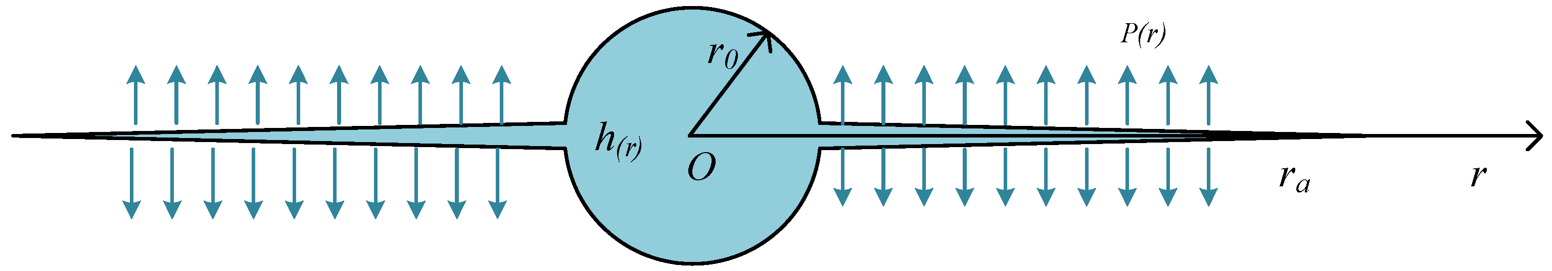
3.3. Fracture Propagation Mechanism of High-Pressure Gas

The rock mass will produce an initial fracture under the action of the CDPTB stress wave, and the high-pressure carbon dioxide after phase change will produce a gas wedge effect along the fracture. The initial fracture continues to expand under the action of high-pressure gas, producing a large range of extended radial fractures in the coal rock body and forming a fracture extension area. The initial crack expands under the quasi-static action of high-pressure gas, which belongs to type I crack. When the stress intensity factor K at the crack tip is greater than the fracture toughness KⅠC of coal and rock mass, the crack will continue to develop. When the stress intensity factor is less than the fracture toughness, the fracture of CDPTB stops expanding and the final fracture state is formed.
Under the action of the stress wave, it is assumed that N initial cracks with an average radius of ra are generated along the borehole wall. The hole center is located at the origin of polar coordinates, and the distributed pressure on the crack surface of rock mass is given by P(r). By using the two-dimensional axisymmetric plane strain mechanical model (Figure 11) to study the blasting problem in infinite rock mass, the dynamic propagation model of plane wedge crack under a quasi-static state of high-pressure carbon dioxide gas can be obtained. The stress intensity factor at the crack tip is as follows [33]:
K I = P r a π r 0 2 + r 0 + r a h r a π r 0 2 + r 0 + r a h r 4 π r .
The fracture mechanism of CDPTB is shown in Figure 12. According to the action principle and action stage, the process of CDPTB can be divided into two different stages: the initiation of the impact stress wave and the expansion of high-pressure gas. The energy source of these two stages is from the rapid phase change of carbon dioxide. Firstly, the impact stress acts around the borehole, generating radial compressive stress and tangential tensile stress around the borehole. Since the tensile strength of rock materials is far less than the compressive strength, and the peak impact stress generated by phase change is between the dynamic compressive strength and tensile strength of the rock mass, the rock mass around the borehole generates a tensile fracture, forming the initial fracture of phase change blasting, and generating a corresponding unloading wave at the fracture. Outside the region where the unloading wave does not propagate, the impact stress continues to generate new tensile fractures. At the time of CDPTB, the coupling effect of the shock wave and unloading wave causes multiple initial fractures around the borehole. The high-pressure gas generated after the carbon dioxide phase change fills the whole fracture. The high-pressure gas acts around the fracture, making the stress intensity factor at the crack tip greater than the fracture toughness of the rock mass, and the fracture expands. When the fracture expands to a certain range, the gas pressure does not decrease enough to drive the fracture expansion, and finally the rock mass is broken.

4. Fracture Characteristics of Carbon Dioxide Phase Transition Blasting

4.1. Overall Characteristics of CDPTB Cracks

In conventional explosive blasting, most of the energy is consumed in the form of shock waves within a range of twice the radius of the blast hole, in which a rock crushing zone is formed. The fracture zone is formed under the joint action of the stress wave and explosive gas. CDPTB forms a medium-impact force and expansion static pressure in the blast hole. The rock mass is cracked and broken along the natural microcracks under the medium impact, and the radial and circumferential cracks are formed under the expansion static pressure. The rock mass is cut into blocks to form a fracture zone, so as to achieve the purpose of fracturing, as shown in Figure 13. The impact stress during CDPTB is low and there will be no strong shock wave and rock crushing zone similar to blasting. Only the initial crack is formed in the rock mass around the blast hole and the initial crack extends and expands to the rock mass around the blast hole under the expansion static pressure, so as to achieve the purpose of breaking the rock. Therefore, CDPTB often produces multiple cracks. When the strength of rock mass is weak, CDPTB will also produce a small fracture zone around the borehole, but its range is far smaller than that of explosive blasting, which greatly improves the utilization rate of rock breaking energy.
Relevant scholars conducted CDPTB [34,35,36,37], and studied the cracks through prefabricated concrete test blocks or primary coal samples. The characteristics of fracture distribution are shown in Figure 13. After the rock mass is broken, 3~8 different fractures will be formed around the borehole, and the concrete block will be divided into several pieces. A small fracture zone is generated in the center of some sample holes, and impact pits are formed on the sample surface.

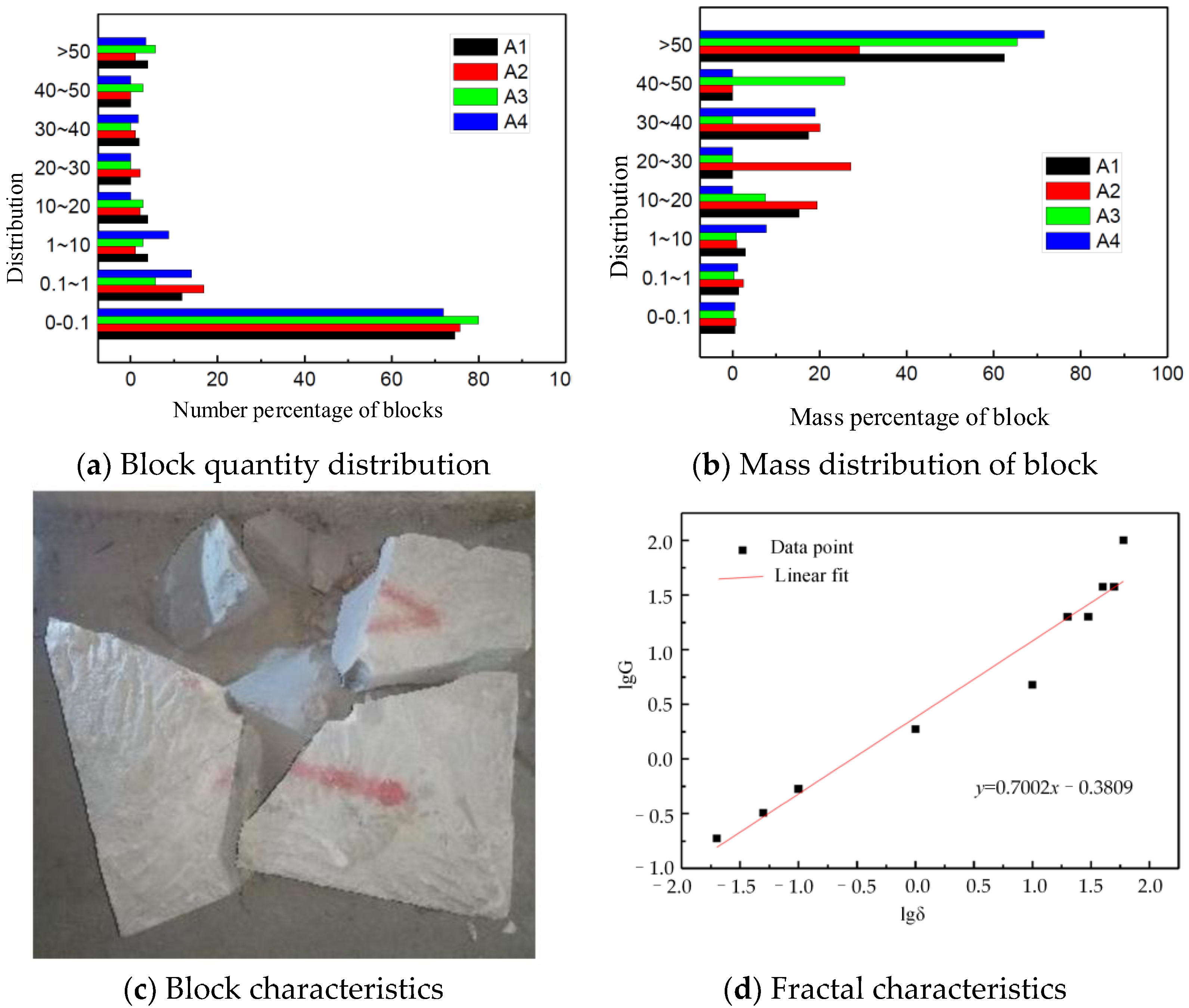
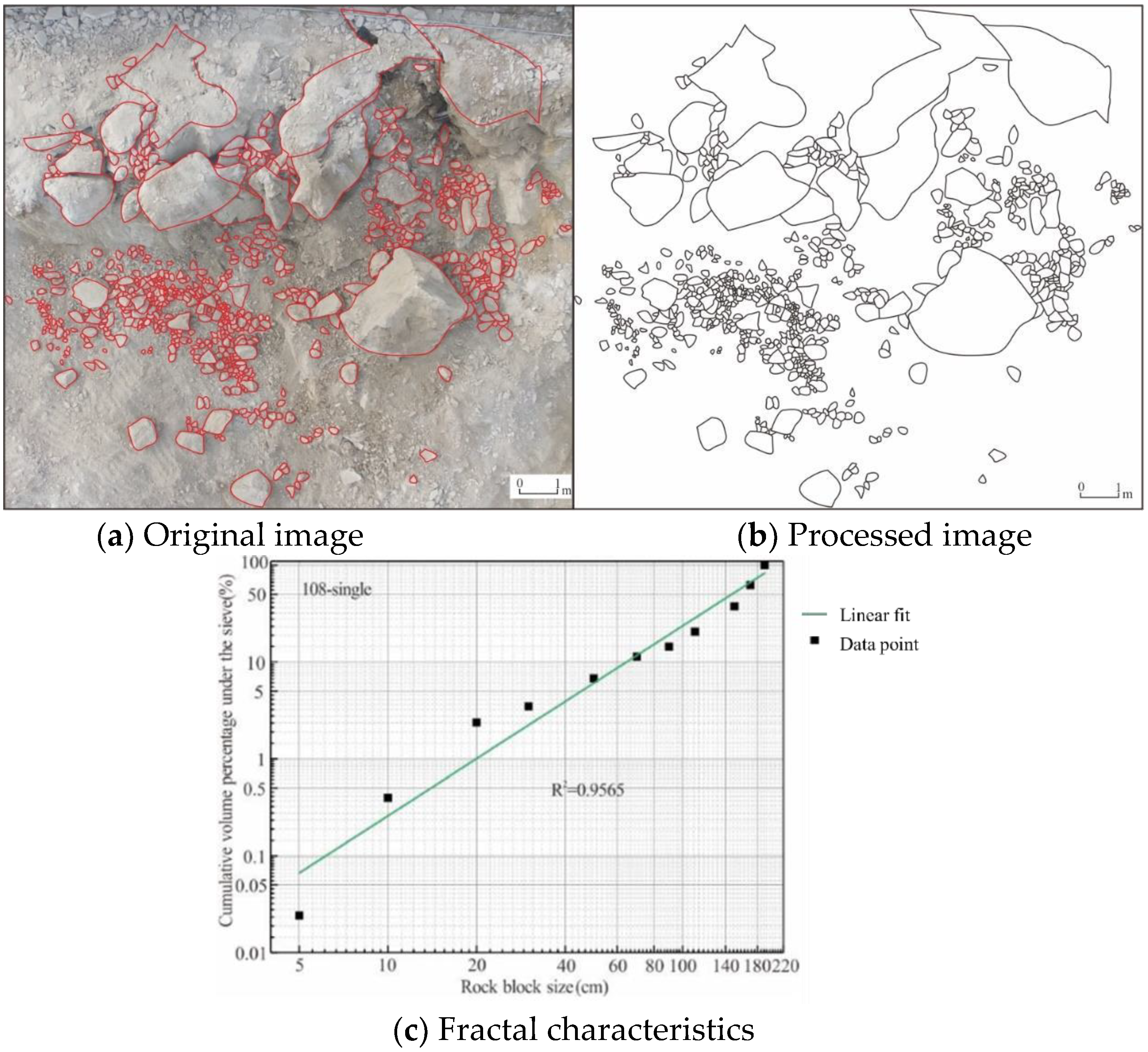
4.2. Macroscopic Fracture Characteristics of CDPTB

A large number of fissures are formed after the fracturing of coal body, and it is impossible to quantitatively describe the exact location, angle and form of each fissure due to different reasons of fissure formation and complex distribution. Therefore, it is an effective way to establish a reasonable evaluation system of coal fracture and determine a reasonable evaluation target. The fractures produced by a specific way often have self-similarity. Relevant scholars [38,39] introduced the fractal theory into the fracture analysis of coal and rock mass, and achieved good results.
Fractal geometry is the science of self-similarity and infinitely detailed images, which can be used to describe irregular phenomena in nature and help to uncover the mechanisms contained within them. The fractal dimension is the basic parameter for the quantitative characterization of fractals, and the calculation of the fractal dimension mainly includes the information dimension, similarity dimension, box counting dimension and Hausdorff dimension. As the calculation of box dimension is simple and can effectively reflect the distribution characteristics of the study subject, it is widely used. The calculation of fracture distribution characteristics of CDPTB is shown in Figure 14. The fracture expansion area is divided into square boxes with side length δk. By calculating the number of boxes containing fractures, if the fracture shows a fractal pattern, the fracture box dimension is as follows.
D = lim k lg N δ k lg N k ,
where: D is the fractal dimension of the fracture; δk is the decreasing sequence of box size; Nδk is the number of boxes containing cracks.
The fractal dimension of CDPTB crack shape is calculated by using the FracLab toolbox in MATLAB. The fracture characteristics of CDPTB are determined by numerical simulation, and the fractal box dimension is calculated, as shown in Figure 15. CDPTB acts on the coal body, resulting in different lengths of cracks from the middle of the borehole to the outside. Due to the small width of the fissures and the tendency of radial expansion, the coal body is split into larger coal seam blocks by CDPTB. Multiple radial fractures are formed in the radial direction of the borehole due to the concentration of blasting energy at locations near the blast hole. With the decay of blasting stress in the coal body and the energy consumption of the fracturing coal body, the energy generated by CDPTB only continues to drive some of the multiple fractures to expand and form the main fractures through the coal body beyond a certain range from the borehole. The fractures produced by CDPTB have good fractal characteristics, and the fitted data points show a linear distribution. CDPTB produces a wide number and range of multiple fractures with a fractal box dimension of 1.78.
At present, the G-G-S distribution or R-R distribution is generally used to describe the distribution of the block in the study of the degree of blast fragmentation. Since the mass of the block is proportional to the block size, the mass distribution of the block can be described by the G-G-S distribution. As shown in Figure 16, the fractal dimension can be obtained by counting the mass distribution of the block after CDPTB [40].
In the field test of CDPTB, the method of “UAV camera shooting + image processing” is adopted to quickly obtain the distribution characteristics of blasting blocks, and the images before and after CDPTB are compared and analyzed to comprehensively evaluate the fracturing effect [41]. The image is pre-processed by using the mean filtering method, and then the image is binarized. The images are divided into two classes according to their grayscale features, and the optimal threshold is determined according to the separation of intra-class variance and inter-class variance. The final image is shown in Figure 17b. The volume of the fractured rock mass by CDPTB can be obtained by transforming the projected area. The fractured rock masses are statistically self-similar in both geometry and fractal distribution. The fractal description of the rock fracture process is as follows: the rock mass will be initially broken into a limited number of blocks with similar shapes; under the load condition, some of the blocks will be decomposed into sub-blocks with a similar shape to the original rock mass; some sub-blocks will be further broken into smaller stones with similar shapes; each repetition of this process will result in smaller blocks. Figure 17c shows the screening percentage and fractal value of phase change blasting cracked rock mass. It is shown through numerous experiments that different CDPTB parameters produce better fractal characteristics, and the higher the percentage of small-sized fragments after rock fragmentation, the larger the fractal dimension.

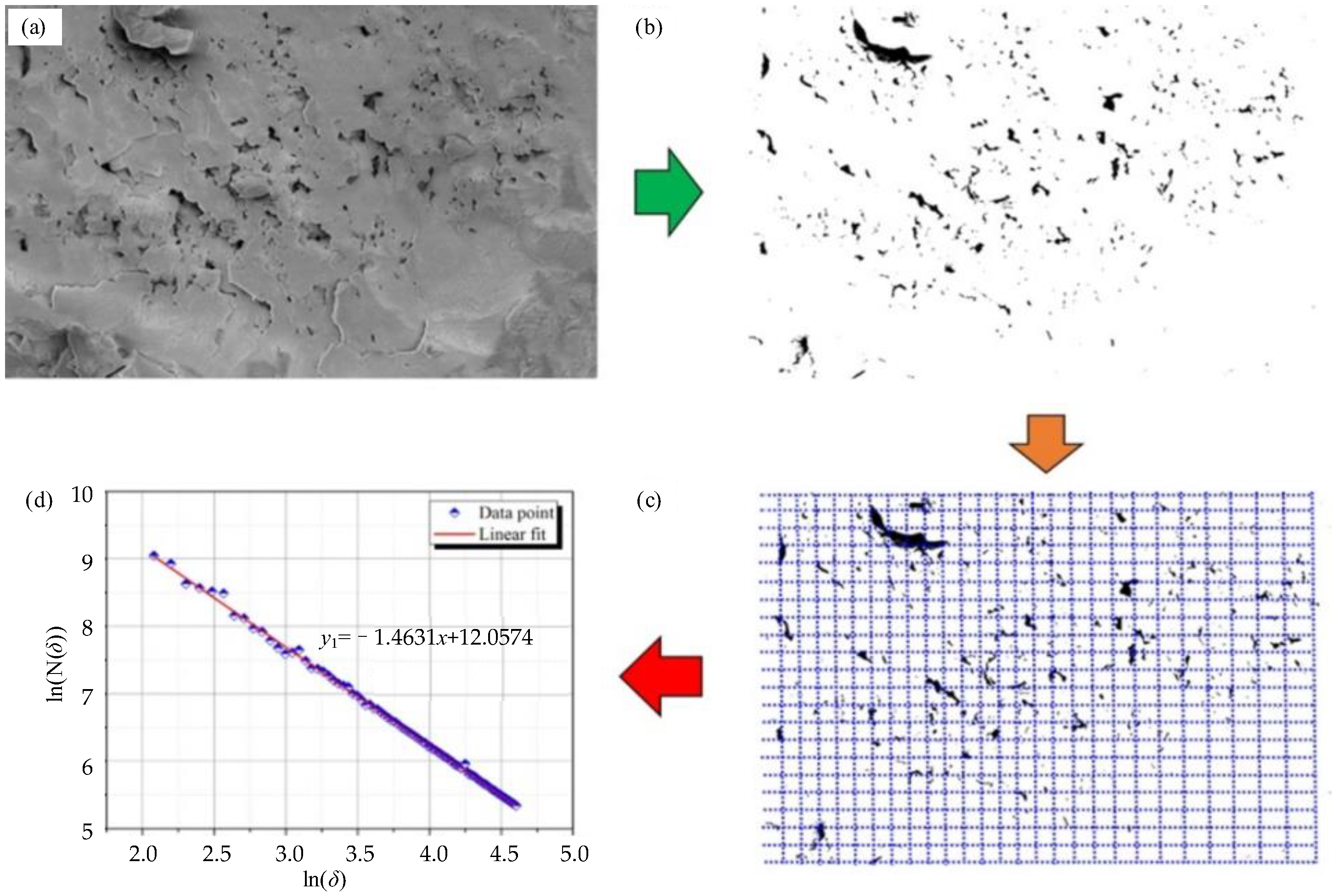
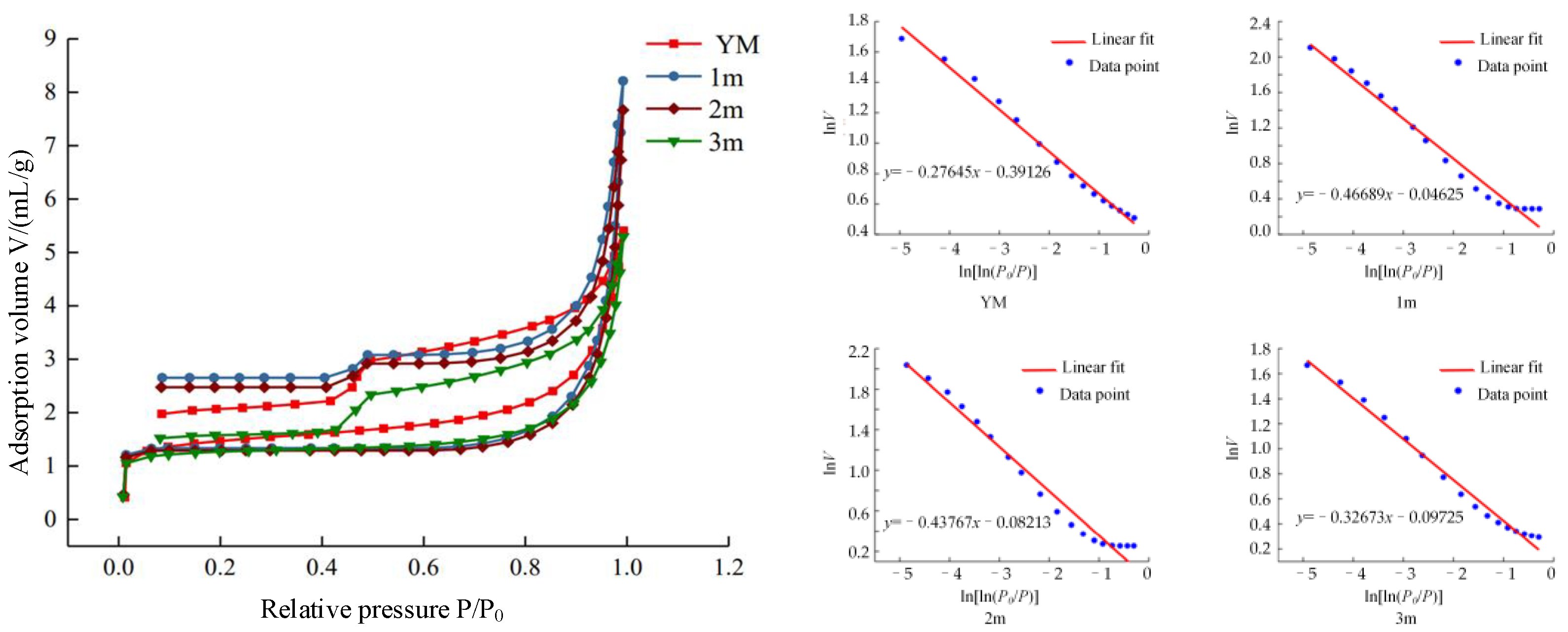
4.3. Microcosmic Fracture Characteristics of CDPTB

CDPTB is widely used in pressure relief and permeability enhancement of high-gas coal seams. The pore structure state of coal seams determines the enrichment and free state of gas. CDPTB changes the pore structure of coal and rock, making the gas in the equilibrium adsorption and free state passively tend to free state. At present, the Hodot pore size classification standard is widely used in coal rock pore test research. According to the Hodot pore classification, the pore testing methods commonly used at this stage are shown in Figure 18. Among them, the low-temperature nitrogen adsorption method has a high accuracy in studying the micropore to mesopore (0.35–300 nm) stage, while the mercury-pressure method has a high accuracy in the macropore section. Fractal theory is a powerful tool not only to characterize the complexity of pore structure but also to describe gas migration in porous media [39].
The SEM images of coal surface morphology before and after CDPTB fracturing are shown in Figure 19. Figure 19A represents the state of the original coal sample, which has widely distributed microporous clusters on the surface and fewer cracks. The pores in the original coal body are not connected, resulting in poor permeability, which is not conducive to gas extraction. After the CDPTB fracturing (Figure 19B–F), there are pores and fractures with different shapes on the surface of the coal sample, and different microfractures connect the original pores, greatly improving the permeability of the coal seam [43]. Fractal theory has been shown to be a powerful tool for quantitative analysis of surface complexity of porous media [44,45,46,47]. Therefore, based on the box counting method, as shown in Figure 20, the fractal dimension D of coal can be obtained from the regression linear slope of the ln(N(δ)) versus ln(δ) curve [47].
A mercury injection test was carried out on coal samples before and after CDPTB. The mercury injection and mercury removal curves of coal samples are shown in Figure 21. The pore volume, average pore diameter and sample porosity of the cracked coal sample are greater than that of the raw coal. It was found that the pore diameter in coal and rock had an obvious fractal dimension change when it was 65 nm. Therefore, pores with a size greater than 65 nm are classified as seepage pores, while pores with a size less than 65 nm are classified as diffusion pores. The fractal dimension of the seepage pores and diffusion pores was fitted by segmenting the 65 nm boundary. The fitting results for the seepage holes are better, and their R2 is greater than 0.95, while their fractal dimension Ds is around 2.65–2.83. The fitting results for diffusion pores are worse than those for seepage pores, with R2 less than 0.95. The fractal dimension DK of diffusion pores is greater than 3, so its practical significance is not obvious. The reason for this situation is that the mercury solution will force the internal cracks of coal and rock pores under the action of external pressure to form new cracks, causing the internal surface of pores to be rough, so that the fractal dimension increases [48].
The nitrogen adsorption method is a method to determine the pore specific surface area and pore size distribution based on the isothermal adsorption curve of nitrogen. The low-temperature nitrogen adsorption method has an advantage over the mercury-pressure method in the determination of micropores because it does not cause damage to the pore structure, and the results are more accurate in the description of micropores. The BET specific surface area ranges from 2.1699 to 2.8108 m2/g, and the BJH pore volume ranges from 0.0040 to 0.0052 mL/g. The specific surface area of the fractured coal samples was smaller than that of the original coal, while the pore volumes were all larger than that of the original coal. The fractal dimension of the pores before and after fracturing is calculated using data with P/P0 at 0.46~1, as shown in Figure 22. The fractal dimension of the fractured coal samples is smaller than that of the original coal. CDPTB has the effect of smoothing the pore walls within the pores [42].

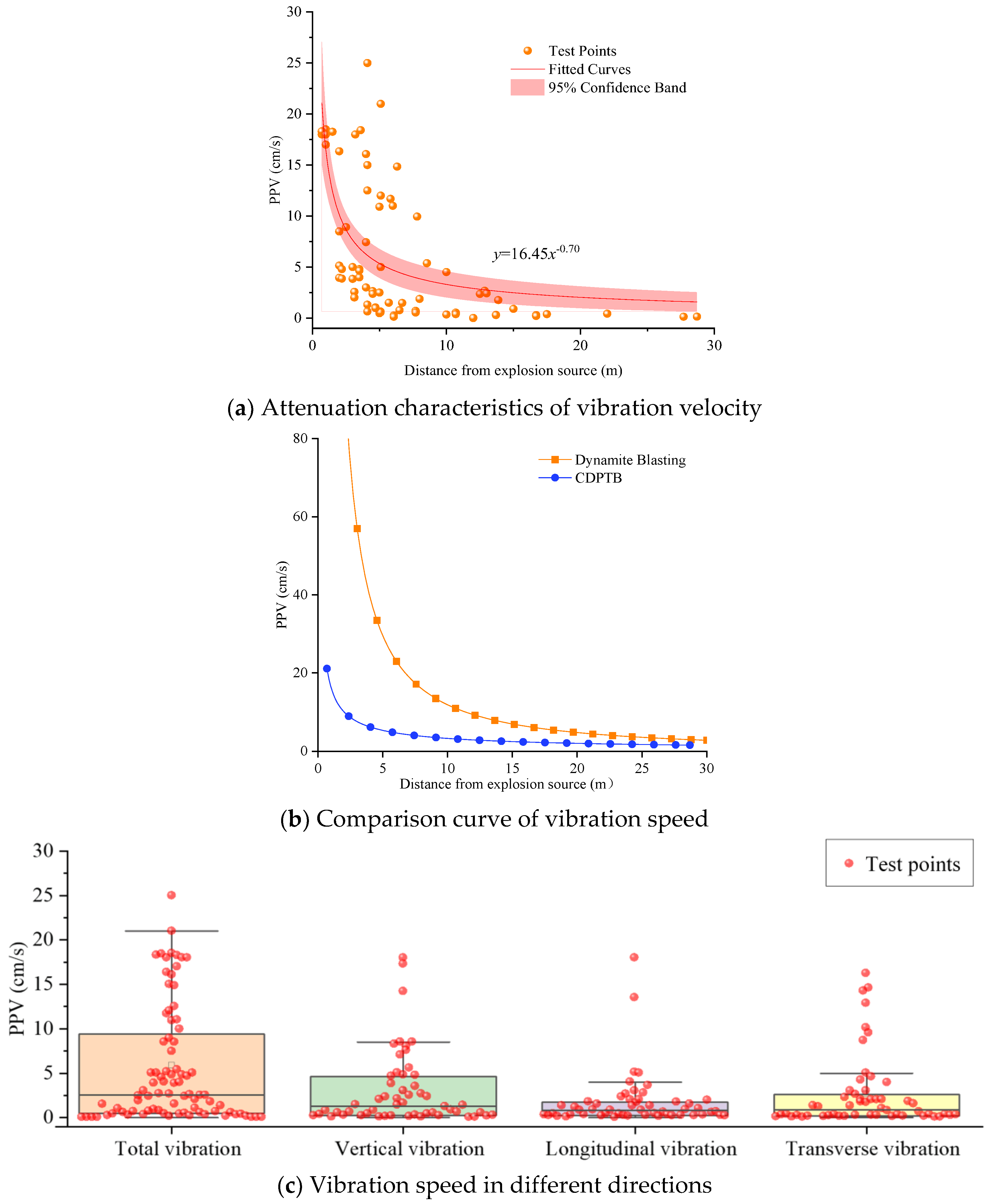
5. Vibration Characteristics of Carbon Dioxide Phase Transition Blasting

5.1. Vibration Attenuation Law

The rock breaking mechanism of CDPTB is similar to that of traditional explosive blasting, which is caused by the coordinated action of a stress wave and gas. CDPTB vibration is excited by the impact of carbon dioxide gas, which belongs to the medium strain rate dynamic impact rock breaking method [49]. As the peak value of the shock wave produced by CDPTB is small, the attenuation speed of the blasting seismic wave is fast, and the vibration speed is at a very low level. However, CDPTB is often used in rock excavation projects in complex and sensitive environments with high vibration control requirements. Its vibration effect cannot be ignored. The vibration velocity and stress of CDPTB decrease with the increase in propagation distance [40,50,51], and the frequency of the vibration velocity curve is 0–100 Hz [52], without high-frequency oscillation [53]. The measured vibration characteristics of different phase change blasting CDPTBs were statistically calculated [3,13,40,41,47,49,51,52,53,54,55,56,57,58], and the variation curve of the vibration velocity caused by CDPTB with the source distance was plotted as shown in Figure 23a. Most of the vibration velocities are below 5 cm/s, and the vibration decays rapidly with increasing distance. Compared with the vibration caused by typical explosive blasting (Figure 10b), the vibration caused by CDPTB is small and can be effectively applied to the scene with high requirements for blasting vibration. At the same time, the vibration caused by CDPTB is different in each direction due to the different principle of CDPTB and the different structure of the air outlet. Figure 23c shows the statistical data of total vibration, vertical vibration, longitudinal vibration and transverse vibration caused by CDPTB.

5.2. Time–Frequency Characteristics of CDPTB

A blasting vibration signal is the carrier and physical manifestation of a blasting seismic wave. Signal analysis and processing are the processes of transforming and identifying the original signal to achieve the desired information and ease of use. For non-stationary signals such as seismic waves, it is desirable to find an analysis method that combines time-domain and frequency-domain analysis, which is expressed mathematically as a two-dimensional function that reflects both the frequency content of the signal and the frequency variation with time, and is known as the time–frequency representation analysis technique [59]. As a typical signal processing method, fast Fourier transform can effectively reveal the amplitude frequency characteristics of the signal, but it cannot accurately describe the instantaneous frequency of the signal and is only applicable to linear stationary signals. In order to better analyze non-stationary signals, wavelet analysis theory is proposed, which has been widely used in blast vibration signal processing because of its good localization characteristics in time and frequency domains. However, wavelet transform is essentially a kind of fast Fourier transform with an adjustable window, which does not get rid of the limitation of fast Fourier transform. In addition, when different wavelet bases are used, the results of signal transformation are also different. Therefore, Huang et al. proposed an empirical modal decomposition method and introduced the approach of Hilbert spectral analysis (Hilbert–Huang transform) [60], which is a good method based on the time-scale characteristics of the data themselves. The Hilbert–Huang transform does not require an a priori basis, which makes the signal processing more flexible. In addition, this method emphasizes the positioning characteristics and avoids the high-frequency and low-frequency errors caused by the fast Fourier transform. Therefore, it is considered as one of the most effective methods for processing non-linear and non-stationary signals, and is widely used in seismic wave analysis, machine fault analysis, image edge detection and other fields [61].
After removing all high-frequency noise components of each monitoring curve, Hilbert transform is applied to IMF components corresponding to different monitoring points to obtain an HHT spectrum. According to the obtained HHT spectrum, the fracturing vibration signal can be further analyzed. The vibration signal energy is mainly distributed from 0–0.7 s. The energy is mainly distributed from 0–48 Hz, and the blast energy distribution is concentrated [62].

6. Engineering Application of Carbon Dioxide Phase Transition Blasting

6.1. Pressure Relief and Permeability Enhancement in High-Gas Seams

After the introduction of CDPTB technology in China, it has been widely used for pressure relief and permeability enhancement in high gas seams [63]. When CDPTB is used to increase the permeability of coal seams, the complex cracks produced by the fracturing destroy the gas adsorption balance, and the gas in the raw coal is gradually desorbed into free state. In addition, carbon dioxide and methane form a competitive adsorption relationship, and can gradually displace methane in coal and rock fractures, which can effectively improve the gas extraction rate. As for the gas treatment methods of high-gas mines, due to the different spatial positions and construction procedures of drilling and coal seams, they can be divided into bedding drilling, advance drilling and cross layer drilling (Figure 24). CDPTB can be applied in different boreholes to generate multiple cracks in the middle of the coal body [64]. After CDPTB fracturing, the permeability of the coal seam increases, the gas extraction concentration and purity are greatly improved and the gas pre-extraction time is shortened.

6.2. Rock Breaking in Urban Engineering Construction

The different rock breaking methods during urban engineering construction are shown in Table 3. The vibration caused by CDPTB is smaller than that caused by traditional blasting. It is advantageous to use CDPTB to break rock in some places with high vibration requirements. The use of CDPTB in urban subway construction can greatly improve construction efficiency and reduce vibration to surrounding buildings. In general engineering construction, it is necessary to break the rock by steps or tunnel pilot holes. CDPTB boreholes are arranged in an explosive blasting-analogous manner as shown in Figure 25. CDPTB safety is outstanding, with the characteristics of weak flying stone, weak vibration and weak noise. The effect on the surrounding existing building environment is small, and personnel basically do not feel the vibration. With reasonable design parameters, there is no need for secondary blasting when the stripped rock block is of medium size.

6.3. Pre-Splitting Blasting in Hard Coal or Rock Mass

In the process of underground mining, due to the hard roof, when the suspended roof of the goaf of the working face exceeds a certain area, it will pose a threat to the normal safety production. CDPTB is used to pre-crack the roof of the working face, because the construction process is simple, safe and reliable, and no harmful gas is generated. The cost is low and good technical and economic benefits are obtained. Phase change blasting holes can be arranged in the direction of gob at the open-off cut to solve the problem of initial mining and top caving. They can also be arranged obliquely above the working face in the mining roadway to solve the problem of a hanging roof at the end of the working face. For the top coal caving face, when the top coal is hard and difficult to collapse, the phase change blasting is used to pre-crack the top coal. After fracturing, the average coal mining volume is increased by 18.6%, and the recovery ratio of top coal is increased by 7.6% [65]. Moreover, the coal body is relatively uniform after fracturing, and the coal block fluidity is good in the coal drawing process, and there is no blockage in the coal drawing. The effect is remarkable.

6.4. Other Applications

In coal mines, in addition to pressure relief and antireflection and pre-splitting roof, CDPTB has also been tried to be applied in coal bunker clearing, vertical shaft uncovering, improving lump coal rate, rock burst prevention and control, gangue pre-splitting, bottom drum treatment, open-pit coal mining and other aspects, and has achieved good results. In the process of mining of other energy minerals, CDPTB provides new ideas for dry heat rock thermal storage construction [66]. For the mining of low-permeability sandstone type uranium ore, CDPTB can realize the rock mass fracture failure under three-dimensional stress conditions, and can effectively increase the distribution of rock mass damage and fracture networks. It has the economic feasibility of breaking rock and increasing permeability, reducing chemical precipitation, etc. It provides a new way to effectively solve the problems of “difficult injection, difficult mining and low recovery” caused by low-permeability in situ leaching of sandstone type uranium ore [67]. In geophysical exploration, CDPTB can be used as a new type of seismic source, which is expected to play an important role in the detection of urban hidden active faults, the detection of urban underground space and the artificial seismic exploration of coal mine high-gas environments [68]. On the whole, CDPTB is gradually being popularized and applied in various rock breaking projects.

7. Research Prospect

As the concept of safe production and green construction continues to gain popularity, safe and environmentally friendly detonation technology will have more development potential than traditional explosive blasting. Although scholars at home and abroad have conducted in-depth research on CDPTB, most of them draw on the theory related to explosive blasting, and there are still problems such as difficulty in fracture control and unstable fracturing effect in practical engineering. In order to further promote the application of phase change blasting technology, it is still necessary to carry out further research work on the mechanism of rock breaking by CDPTB, the design and optimization of CDPTB devices, the influence characteristics of cracks on CDPTB and the design and optimization of CDPTB parameters.
(1) Mechanism of rock breaking by CDPTB
CDPTB is a coordinated action of stress waves and high-pressure gas, but the ratio of the two energies to the rock breaking effect is not yet clear. The shock wave caused by CDPTB is smaller and longer than the peak of explosive blasting, and it will produce multiple fractures around the rock. However, there is a lack of quantitative description of the fracture initiation characteristics of medium-stress waves, and the number of fractures cannot be quantitatively calculated. Therefore, there is an urgent need to establish the quantitative relationship between the action of medium shock waves from CDPTB and to clarify the mechanism of rock breaking by CDPTB.
(2) The design and optimization of CDPTB devices
At present, most CDPTB uses reusable tubes, and the blasting energy is affected by the carbon dioxide filling amount, the thickness of the shear energy release plate and the shape and position of the release port. The disposable phase change blasting device can control the direction of energy discharge by scoring. However, the relationship between the structural characteristics of different CDPTB devices and the effect of CDPTB is still unclear. How to select the appropriate phase change blasting device according to the characteristics of different rock masses to achieve the best rock breaking effect still needs to be clarified.
(3) The influence of characteristics of cracks on CDPTB
The source power of phase change blasting for rock breaking comes from the high-pressure carbon dioxide gas generated by phase change. However, there are often a large number of primary fissures in the project rock, which may form gas leakage channels, causing dissipation of CDPTB energy, weakening the rock breaking effect. It may also have an induced effect on phase change blasting fractures. The influence mechanism of cracks on phase change blasting should be explored to realize reasonable induction and utilization of different cracks.
(4) The design and optimization of CDPTB parameters
The design of the drilling and initiating network of CDPTB is often based on traditional blasting, and the design specification of hole network parameters based on the principle of CDPTB has not been formed. Different rock breaking projects have different geological environments and expected targets, and CDPTB cannot simply rely on engineering experience. It is necessary to reveal the influence of geological factors such as rock strength, fissures and laminae, as well as blasting parameters such as charging volume, detonation time and sequence on the effect of rock breaking in complex geological environments, so as to establish specifications for the design of CDPTB parameters and expand the application of CDPTB.

8. Conclusions

(1) CDPTB has the characteristics of good safety, environmental friendliness and controllability. It mainly relies on the high-pressure gas generated by the rapid phase change of carbon dioxide in the liquid storage pipe to do work, which belongs to physical changes. According to the characteristics of phase change blasting devices, they can be divided into reusable equipment and disposable equipment. The average value of CDPTB energy per unit mass of carbon dioxide is 825.5 KJ, and the median value is 618.3 KJ.
(2) CDPTB is composed of a shock wave and high-pressure gas. The medium shock wave produces tensile fractures around the blasting hole, and multiple initial fractures are produced under the combined action of an unloading wave and impact wave. The high-pressure gas expands along the initial fracture and finally forms the fracture of the rock mass.
(3) Due to the small-impact stress, there is little or no crushing zone near the blasting hole in CDPTB. The fracture produced by CDPTB presents fractal characteristics in the distribution of macroscopic fracture and fragmentation. At the micro level, the microfracture and pore characteristics of CDPTB also show fractal characteristics. The vibration produced by CDPTB is small and has obvious directionality.
(4) CDPTB technology is widely used in the fields of pressure relief and permeability enhancement in high-gas seams, rock breaking in urban engineering construction, pre-splitting blasting of hard coal and rock masses and it has expanded to new seismic sources, geothermal mining and other fields. The cloud model can be used to reasonably evaluate the rock mass phase change blasting crack ability.
(5) In order to further promote the application of phase change blasting technology, it is still necessary to carry out further research on the mechanism of rock breaking by CDPTB, the design and optimization of CDPTB devices, the influence of characteristics of cracks on CDPTB and the design and optimization of CDPTB parameters.

Author Contributions

Conceptualization, Z.C. and Y.Y.; methodology, Z.C. and C.Y.; software, W.W.; validation, Z.Q. and C.Y.; formal analysis, Z.C.; investigation, W.W.; resources, Y.Y.; data curation, Z.C.; writing—original draft preparation, Z.C. and Y.Y.; writing—review and editing, Z.C.; visualization, W.W.; supervision, Y.Y.; project administration, Z.C. and C.Y.; funding acquisition, Y.Y. All authors have read and agreed to the published version of the manuscript.

Funding

Financial support for this work was provided by the National Natural Science Foundation of China (51974294), the Qing Lan Project of Jiangsu Province Universities (2022).

Institutional Review Board Statement

Not applicable.

Informed Consent Statement

Not applicable.

Data Availability Statement

The original contributions presented in the study are included in the articlel, further inquiries can be directed to the corresponding author.

Conflicts of Interest

The authors declare no conflict of interest.

References

  1. Pal Roy, P. Emerging trends in drilling and blasting technology: Concerns and commitments. Arab. J. Geosci. 2021, 14, 652. [Google Scholar] [CrossRef]
  2. Shang, J.; Zhao, Z.; Aliyu, M. Stresses induced by a demolition agent in non-explosive rock fracturing. Int. J. Rock Mech. Min. Sci. 2018, 107, 172–180. [Google Scholar] [CrossRef]
  3. Li, Q.Y.; Chen, G.; Luo, D.Y.; Ma, H.P.; Liu, Y. An experimental study of a novel liquid carbon dioxide rock-breaking technology. Int. J. Rock Mech. Min. Sci. 2020, 128, 104244. [Google Scholar] [CrossRef]
  4. Wladzielczyk, K.; Ghose, A.K. Environment-Friendly Techniques of Rock Breaking; Routledge: London, UK, 2021. [Google Scholar]
  5. Zhou, X.; Men, J.; Song, D.; Zhao, H. Research on increasing coal seam permeability and promoting gas drainage with liquid CO2 blasting. China Saf. Sci. J. 2015, 2, 60–65. [Google Scholar]
  6. Chen, S.L.; Huang, B.X.; Zhao, X.L.; Lu, W.Y.; Tian, Z.C. Directional fracturing excavation technology based on liquid CO2 phase transition in freezing shaft sinking. Energy Sources Part A Recovery Util. Environ. Eff. 2020, 1–15. [Google Scholar] [CrossRef]
  7. Zhu, W.C.; Gai, D.; Wei, C.H.; Li, S.G. High-pressure air blasting experiments on concrete and implications for enhanced coal gas drainage. J. Nat. Gas Sci. Eng. 2016, 36, 1253–1263. [Google Scholar] [CrossRef] [Green Version]
  8. Schooler, D.R. The Use of Carbon Dioxide for Dislodging Coal in Mines. Ph.D. Thesis, Missouri University of Science and Technology, Rolla, MO, USA, 1944. [Google Scholar]
  9. Weir, P.; Edwards, J. Mechanical loading and Cardox revolutionize an old mine. Coal Age 1928, 33, 288–290. [Google Scholar]
  10. Lu, T.K.; Wang, Z.F.; Yang, H.M.; Yuan, P.J.; Han, Y.B.; Sun, X.M. Improvement of coal seam gas drainage by under-panel cross-strata stimulation using highly pressurized gas. Int. J. Rock Mech. Min. Sci. 2015, 77, 300–312. [Google Scholar] [CrossRef]
  11. Cao, Y.; Zhang, J.; Tian, L.; Zhai, H.; Fu, G.; Tang, J. Research and application of CO2 gas fracturing for gas control in low permeability coal seams. J. China Coal Soc. 2017, 42, 2631–2641. [Google Scholar]
  12. Nie, Z. Application of cardox dioxide blasting technique in coal mines. Coal Technol. 2007, 26, 36–37. [Google Scholar]
  13. Mei, B.; Gao, X.; Fang, Y.; Zhu, Z.; Zhang, B. Study on a New Type of Fracturing Tube and Safety Technology of Carbon Dioxide Expansion Blasting. Blasting 2021, 2, 153–159. [Google Scholar]
  14. Dong, Q.; Wang, Z.; Han, Y.; Sun, X. Research on TNT equivalent of liquid CO2 phase-transition fracturing. China Saf. Sci. J. 2014, 24, 84–88. [Google Scholar]
  15. Zhou, K.; Ke, B.; Li, J.; Zhang, Y.; Cheng, L. Pressure dynamic response and explosion energy of liquid carbon dioxide blasting system. Blasting 2017, 34, 7–13. [Google Scholar]
  16. Guo, Y. Fracturing Mechanisms and Functions of Improvement of Gas Drainage of Highly Pressurized Carbon Dioxide Gas System; Henan Polytechnic University: Jiaozuo, China, 2017. [Google Scholar]
  17. Yang, X.L.; Wen, G.C.; Sun, H.T.; Li, X.L.; Lu, T.K.; Dai, L.C.; Gao, J.; Li, L. Environmentally friendly techniques for high gas content thick coal seam stimulation-multi-discharge CO2 fracturing system. J. Nat. Gas Sci. Eng. 2019, 61, 71–82. [Google Scholar] [CrossRef]
  18. Fan, Y.C.; Qin, B.T.; Zhou, Q.; Shi, Q.L.; Wu, J.H. Liquid CO2 phase transition fracturing technology and its application in enhancing gas drainage of coal mines. Adsorpt. Sci. Technol. 2020, 38, 393–412. [Google Scholar] [CrossRef]
  19. Hu, G.Z.; He, W.R.; Sun, M. Enhancing coal seam gas using liquid CO2 phase-transition blasting with cross-measure borehole. J. Nat. Gas Sci. Eng. 2018, 60, 164–173. [Google Scholar] [CrossRef]
  20. Yang, Z.B.; Zhou, Y.J.; Xu, X.D.; Yi, W.; Li, M.P.; Li, X.T. Numerical Modelling of Liquid CO2 Phase Transition Blasting Based on Smoothed Particle Hydrodynamics Algorithm. Therm. Sci. 2019, 23, S693–S702. [Google Scholar] [CrossRef]
  21. Liu, D.W.; Tang, Y.; Cai, C.W.; Jian, Y.H. A Rock Fracturing Method Using High-Pressure Gas Expansion: Case Study on Its Application in Hangzhou-Lin’an Intercity Railway. Adv. Civ. Eng. 2021, 2021, 6654471. [Google Scholar] [CrossRef]
  22. Kang, J.H.; Zhou, F.B.; Qiang, Z.Y.; Zhu, S.J. Evaluation of gas drainage and coal permeability improvement with liquid CO2 gasification blasting. Adv. Mech. Eng. 2018, 10, 1–15. [Google Scholar] [CrossRef] [Green Version]
  23. Bai, X.; Zhang, D.M.; Zeng, S.; Zhang, S.W.; Wang, D.K.; Wang, F.L. An enhanced coalbed methane recovery technique based on CO2 phase transition jet coal-breaking behavior. Fuel 2020, 265, 116912. [Google Scholar] [CrossRef]
  24. Cheng, W. Borehole parameter optimization for supercritical carbon dioxide phase-transition fracturing. In IOP Conference Series: Earth and Environmental Science; IOP Publishing: Bristol, UK, 2020; p. 042025. [Google Scholar]
  25. Ye, W.; Lu, Y.; Xi, L.; Zhang, Q.; Hu, S. Vibration Effect Induced by Rock Breaking Technology Based on Dry Ice and Energy-gathered Agent in Trench Excavation. J. Phys. Conf. Ser. 2022, 2148, 012023. [Google Scholar] [CrossRef]
  26. Wang, B.; Li, H.B.; Shao, Z.S.; Chen, S.A.; Li, X.F. Investigating the mechanism of rock fracturing induced by high-pressure gas blasting with a hybrid continuum-discontinuum method. Comput. Geotech. 2021, 140, 104445. [Google Scholar] [CrossRef]
  27. Hong, L.; Li, X.; Ma, C.; Yin, T.; Ye, Z.; Liao, G. Study on size effect of rock dynamic strength and strain rate sensitivity. Chin. J. Rock Mech. Eng. 2008, 27, 526–533. [Google Scholar]
  28. Hu, S.B.; Pang, S.G.; Yan, Z.Y. A new dynamic fracturing method: Deflagration fracturing technology with carbon dioxide. Int. J. Fract. 2019, 220, 99–111. [Google Scholar] [CrossRef]
  29. Wang, H.; Chang, L.; Liu, Q. Enhanced CMM Drainage with High-pressure Gas Fracturing: A Novel Way to Control Greenhouse Gas Emissions in the Coal Mine. J. Residuals Sci. Technol. 2017, 14, 57–66. [Google Scholar]
  30. Chen, Z. Fracture-Seepage Evolution Law by Carbon Dioxide Phase Change Blasting in Low Permeability Coal Seam; China University of mining and technology: Beijing, China, 2019. [Google Scholar]
  31. Zheng, Y.; Zhou, F.; Hu, S.; Yu, T.X. Fragmentations of solids under impact tension. Adv. Mech. 2016, 46, 506–540. [Google Scholar]
  32. Mott, N.F. Fragmentation of shell cases. Proc. R. Soc. Lond. A Math. Phys. Sci. 1947, 189, 300–308. [Google Scholar]
  33. Gao, F.; Tang, L.H.; Zhou, K.P.; Zhang, Y.A.; Ke, B. Mechanism Analysis of Liquid Carbon Dioxide Phase Transition for Fracturing Rock Masses. Energies 2018, 11, 2909. [Google Scholar] [CrossRef] [Green Version]
  34. Bai, X. Research on Mechanism and Application of Liquid Carbon Dioxide Phase Change Jet Fracturing Coal Seam to Increase Gas Permeability; Chongqing University: Chongqing, China, 2019. [Google Scholar]
  35. Shang, Z.; Wang, H.F.; Li, B.; Cheng, Y.P.; Zhang, X.H.; Zhao, F.; Zhang, X.; Hao, C.M.; Wang, Z.Y. Fracture processes in coal measures strata under liquid CO2 phase transition blasting. Eng. Fract. Mech. 2021, 254, 107902. [Google Scholar] [CrossRef]
  36. Yang, X.L.; Wang, C.; Chu, H.B.; Yan, S.Y.; Wei, H.X.; Yu, M.F. Study on the Stress Field and Crack Propagation of Coal Mass Induced by High-Pressure Air Blasting. Minerals 2022, 12, 300. [Google Scholar] [CrossRef]
  37. Shang, Z.; Wang, H.; Li, B.; Cheng, Y.; Zhang, X.; Wang, Z.; Geng, S.; Wang, Z.; Chen, P.; Lv, P.; et al. The effect of leakage characteristics of liquid CO2 phase transition on fracturing coal seam: Applications for enhancing coalbed methane recovery. Fuel 2022, 308, 122044. [Google Scholar] [CrossRef]
  38. Gao, F.; Xie, H.-P.; Zhao, P. Fractal properties of size-frequency distribution of rock fragments and the influence of meso-structure. Chin. J. Rock Mech. Eng. 1994, 13, 240–246. [Google Scholar]
  39. Xia, B.W.; Liu, X.F.; Song, D.Z.; He, X.Q.; Yang, T.; Wang, L.K. Evaluation of liquid CO2 phase change fracturing effect on coal using fractal theory. Fuel 2021, 287, 119569. [Google Scholar] [CrossRef]
  40. Ke, B. Experimental Study on Phase Transition Dynamic of Supercritical Carbon Dioxide and Its Rock Breaking Mechanism; Central South University: Changsha, China, 2017. [Google Scholar]
  41. Sui, H.Y.; Su, T.M.; Hu, R.L.; Yang, K.; Cheng, Y.X. Liquid CO2 Phase-Transition Rock Fracturing: A Novel Technology for Safe Rock Excavation. Appl. Sci. 2022, 12, 69. [Google Scholar] [CrossRef]
  42. Peng, X. Experimental Study on Mechanism of CO2 Fracturing and Enhancing Permeability Based on Fractal Theory in Guizhou Soft Coal Seam; Guizhou University: Guiyang, China, 2022. [Google Scholar]
  43. Liao, Z.; Liu, X.; Song, D.; He, X.; Nie, B.; Yang, T.; Wang, L. Micro-structural Damage to Coal Induced by Liquid CO2 Phase Change Fracturing. Nat. Resour. Res. 2020, 30, 1613–1627. [Google Scholar] [CrossRef]
  44. Alfonso, I.; Beltran, A.; Abatal, M.; Castro, I.; Fuentes, A.; Vazquez, L.; Garcia, A. Fractal Dimension Determination of Rock Pores by Multi-Scale Analysis of Images Obtained Using OM, SEM and XCT. Fractals-Complex Geom. Patterns Scaling Nat. Soc. 2018, 26, 1850067. [Google Scholar] [CrossRef]
  45. Li, H.; Shi, S.L.; Lin, B.Q.; Lu, J.X.; Ye, Q.; Lu, Y.; Wang, Z.; Hong, Y.D.; Zhu, X.N. Effects of microwave-assisted pyrolysis on the microstructure of bituminous coals. Energy 2019, 187, 115986. [Google Scholar] [CrossRef]
  46. Morales, F.A.; Aristizabal, L.C. A Discussion on the Transmission Conditions for Saturated Fluid Flow through Porous Media with Fractal Microstructure. Fractals-Complex Geom. Patterns Scaling Nat. Soc. 2019, 27, 1950033. [Google Scholar] [CrossRef]
  47. Liu, X.F.; Wang, Z.P.; Song, D.Z.; He, X.Q.; Yang, T. Variations in surface fractal characteristics of coal subjected to liquid CO2 phase change fracturing. Int. J. Energy Res. 2020, 44, 8740–8753. [Google Scholar] [CrossRef]
  48. Guo, Y.; Jiang, Z.; Peng, X.; Fu, X.; Wu, S.; Quan, X.; Yang, X. Experimental study on the influence of carbon dioxide cracking on coal pore structure. Saf. Coal Mines 2022, 53, 1–7. [Google Scholar]
  49. Yang, Y.; Zhu, X. Experimental Study on Vibration Attenuation Law of Liquid CO2 Gas Blasting Rock. Subgrade Eng. 2021, 1, 104–108. [Google Scholar]
  50. Sun, K.; Xin, L.; Wu, D.; Wang, J. Simulation of fracture law of supercritical CO2 explosion under initial stress condition CO2. Zhendong Yu Chongji/J. Vib. Shock 2018, 37, 232–238. [Google Scholar]
  51. Liu, X.; Li, Q.; Feng, G.; Chen, G.; Xie, X. Vibrational energy distribution of rock broken by phase transition of liquid carbon dioxide. Min. Metall. Eng 2018, 38, 5–10. [Google Scholar]
  52. Chen, G.; Li, Q.; Liu, X.; Wu, Z.; Ma, J. Research on energy distribution characters about liquid CO2 phase-transition broken rock vibration signal. Blasting 2018, 35, 155–163. [Google Scholar]
  53. Tao, M.; Zhao, H.; Li, X.; Ma, A. Comprehensive comparative analysis of liquid CO2 phase change fracturing and explosive rock fracturing. Blasting 2018, 35, 41–49. [Google Scholar]
  54. Xie, X.; Li, X.; Li, Q.; Ma, H.; Liu, X. Liquid CO2 phase-transforming rock fracturing technology in pile-well excavation CO2. Zhongnan Daxue Xuebao (Ziran Kexue Ban)/J. Cent. South Univ. (Sci. Technol.) 2018, 49, 2031–2038. [Google Scholar]
  55. Yuan, H.; Chen, C.; Yu, J.; Liu, X.; Dong, B. Liquid CO2 Phase Change Fracturing and Vibration Monitoring in Roadbed Slope Excavation. In Proceedings of the 2021 International Conference on Internet of Things and Smart City, IoTSC 2021, Kunming, China, 4–6 June 2021. [Google Scholar]
  56. Li, Q.; Liu, X.; Wu, Z.; Xie, X. Application of liquid CO2 phase change rock breaking technology in metro foundation pit excavation. J. Railw. Sci. Eng 2018, 15, 163–169. [Google Scholar]
  57. Xie, X.; Li, X.; Li, Q.; Ma, H.; Fang, Y.; Liu, X. Research and review about the liquid CO2 phase-transforming rock fracturing technology. J. Railw. Sci. Eng 2018, 15, 1406–1414. [Google Scholar]
  58. Liu, S.; Huang, Z. Feasibility study on the application of carbon dioxide phase change fracturing technology in a foundation pit of an open cut tunnel. In Proceedings of the 43rd International Conference on Vibroengineering, Greater Noida, India, 28–30 November 2019; pp. 295–300. [Google Scholar]
  59. Ke, B.; Zhou, K.; Li, J.; Zhang, Y.; Shi, W.; Cheng, L.; Yang, J. Time-frequency Analysis of Seismic Wave for Liquid CO2 Blasting System. Blasting 2017, 34, 137–142. [Google Scholar]
  60. Huang, N.E.; Shen, Z.; Long, S.R.; Wu, M.C.; Shih, H.H.; Zheng, Q.; Yen, N.-C.; Tung, C.C.; Liu, H.H. The empirical mode decomposition and the Hilbert spectrum for nonlinear and non-stationary time series analysis. Proc. R. Soc. London. Ser. A Math. Phys. Eng. Sci. 1998, 454, 903–995. [Google Scholar] [CrossRef]
  61. Liu, J.C.; Gao, W.X. Vibration Signal Analysis of Water Seal Blasting Based on Wavelet Threshold Denoising and HHT Transformation. Adv. Civ. Eng. 2020, 2020, 4381480. [Google Scholar] [CrossRef] [Green Version]
  62. Zhou, S.T.; Luo, X.D.; Jiang, N.; Zhang, S.T.; Lei, Y. Ground vibration characteristics of carbon dioxide phase transition fracturing: An in situ test. Bull. Eng. Geol. Environ. 2021, 80, 9029–9047. [Google Scholar] [CrossRef]
  63. Chen, Z.S.; Yuan, Y.; Wang, W.M.; Zhu, C.; Qin, Z.H.; Yan, C.L. Pressure Relief and Permeability Enhancement with Carbon Dioxide Phase Transition Blasting: Fracture, Seepage, and Practice. Lithosphere 2021, 2021, 4983754. [Google Scholar] [CrossRef]
  64. Yuan, Y.; Zuo, L.; Chen, Z.S.; Meng, C.G.; Yan, C.L.; Gong, Z.X. Improvement of coalbed methane recovery rate by carbon dioxide phase transition blast fracturing. Energy Sources Part A Recovery Util. Environ. Eff. 2022, 44, 3659–3672. [Google Scholar] [CrossRef]
  65. Liu, D. Application of Liquid Carbon Dioxide Phase Change Cracking Weakening Top Coal Technology in Extra Thick Coal Seam. Mod. Min. 2021, 37, 68–70. [Google Scholar]
  66. Xia, J.; Dou, B.; Xu, C.; Tian, H.; Zheng, J.; Cui, G.; Gu, J.; Chen, J. Optimum design of CO2 fracture initiator for thermal reservoir construction in hot dry rock. Drill. Eng. 2021, 48, 75–80. [Google Scholar]
  67. Xin, B.; Sheng, L.G.W.Y.Z.; Nili, X.X.F. Feasibility Study on Enhanced Permeability of Low Permeability Sandstone Type Uranium Deposit with Liquid CO2 Phase Transition Fracturing. Met. Mine 2021, 50, 50. [Google Scholar]
  68. Li, W.; Chen, Y.; Wang, F.Y.; Cao, Y.X.; Wang, H.Z.; Tian, L.; Xu, Y.; Guo, X.J.; Feng, S.Q.; Hu, X.P. Feasibility study of developing one new type of seismic source via carbon dioxide phase transition. Chin. J. Geophys. Chin. Ed. 2020, 63, 2605–2616. [Google Scholar]
Figure 1. Principle of carbon dioxide phase transition blasting.
Processes 10 02434 g001
Figure 2. Structure diagram and jet characteristics of different phase change blasting devices.
Processes 10 02434 g002
Figure 3. Carbon dioxide phase transition blasting equipment.
Processes 10 02434 g003
Figure 4. CDPTB energy distribution.
Processes 10 02434 g004
Figure 5. Strain rate classification characteristics and fracture mode distribution.
Processes 10 02434 g005
Figure 6. Pressure time history curve of different fracturing methods.
Processes 10 02434 g006
Figure 7. Stress analysis of borehole.
Processes 10 02434 g007
Figure 8. Stress characteristics around blasting holes.
Processes 10 02434 g008
Figure 9. Stress characteristics around blasting borehole when lateral pressure coefficient is 0.
Processes 10 02434 g009
Figure 10. Initiation mechanism of phase change impact stress.
Processes 10 02434 g010
Figure 11. Dynamic propagation model of planar wedge cracks in infinite rock mass.
Processes 10 02434 g011
Figure 12. Fracture mechanism of carbon dioxide phase transition blasting.
Processes 10 02434 g012
Figure 13. Overall characteristics of CDPTB cracks. (a) Schematic diagram of CDPTB fracture characteristics; (b) Experimental result from Bai [34]; (c) Experimental result from Shang et al. [35]; (d) Experimental result from Yang et al. [36]; (e) Experimental result from Shang et al.[37].
Processes 10 02434 g013aProcesses 10 02434 g013b
Figure 14. Schematic diagram of fractal box dimension calculation principle.
Processes 10 02434 g014
Figure 15. Distribution and fractal characteristics of CDPTB fractures.
Processes 10 02434 g015
Figure 16. Block distribution and fractal characteristics of CDPTB sample [40].
Processes 10 02434 g016
Figure 17. Distribution and fractal characteristics of CDPTB cracked blocks [41].
Processes 10 02434 g017
Figure 18. Pore characterization method of coal or rock mass [42].
Processes 10 02434 g018
Figure 19. SEM images of surface morphology for studied samples [47].
Processes 10 02434 g019
Figure 20. Box counting method for the calculation of DF [47].(a) Rriginal image, (b) Processed image, (c) Fractal box division, (d) Fractal curve fitting.
Processes 10 02434 g020
Figure 21. Mercury injection test curve and fractal characteristics [48].
Processes 10 02434 g021
Figure 22. Isothermal curve of liquid nitrogen adsorption and fractal curve [42].
Processes 10 02434 g022
Figure 23. Vibration velocity characteristics of CDPTB.
Processes 10 02434 g023
Figure 24. Pressure relief and permeability enhancement mode of high-gas coal seam.
Processes 10 02434 g024
Figure 25. Drilling layout plan for engineering construction. (a) Step single-row one-line type of foundation pit slope; (b) Step plum-shaped foundation pit slope; (c) Parallel hole of subway tunnel; (d) Cutting hole of subway tunnel.
Processes 10 02434 g025
Table 1. Calculation method of CDPTB energy.
Calculation
Principle
Calculation FormulaCO2 Blasting Energy per Unit Mass/KJTNT Equivalent/gEvaluation
Compressed gas and water vapor containersFormula (1)385.1~1256.490.6
~295.6
It is widely used, the parameters are easy to obtain, the calculation is simple, the calculation result of explosion energy is small, the influence of temperature on explosion energy is not considered and the influence of volume on explosion energy is large.
Jet velocityFormula (2)562.8~641.3132.2
~150.6
The influence of volume and mass on explosion energy is not considered, so there is a large error.
Volume of gaseous explosion productsFormula (3)1687.3397.0The volume of gaseous explosion products is affected by factors such as explosive ratio, and the result may not be very accurate.
Blasting vibrationFormula (4)1615~2827.5380.0
~430.0
The indirect test of blasting vibration requires on-site blasting test, with large quantities.
Real state equationFormula (5) Formula (6)327.3~125077.0
~294.1
The thermodynamic characteristic of CO2 is a real equation of state, with high calculation accuracy and complex calculation.
Table 2. Technical parameters of different fracturing methods.
TypeRise Time (s)Peak Pressure (Mpa)Loading Rate (Mpa/s)Total Times (s)
Blasting10−7104>10810−6
CDPTB fracturing10−3102102~10610−2
Hydraulic fracturing10210<10−1104
Table 3. Comparison of different rock breaking methods.
Traditional BlastingExpansive Agent, Hydraulic TongsHydraulic HammerCDPTB
MechanismDetonation wave, and impact on the fractured rock massStatic crushing, expansion agent flows into the rock mass along the hole wall crack, resulting in the fracture of the protection areaHydraulic hammer mechanical crushingCarbon dioxide phase change generates high-pressure gas in the hole, and the gas pressure is lower than the explosion pressure of the explosive
Motive powerChemical reactionChemical agents, hydraulicMachineryPhysical work
TechnologySpecial operation, strict approval requirements and complicated technologyLess used in large-volume sub-firm rock excavationsSimple and easy to use, high-strength rock crushing difficultiesWide range of sources, simple approval, complex technology
SecurityHigh safety requirements, high evacuation and alert requirements, high dustSilent, no flyrock, no pollution to the environment, no vibrationLess flyrock and high noiseLow vibration, less flyrock, no environmental pollution
EfficiencyHigh rock breaking efficiency and low labor intensityLong time, uncertain expansion direction and low rock breaking efficiencyLow rock breaking efficiency and high labor intensityShort time, requiring the assistance of excavators
Cost20 RMB/m3100 RMB/m3100 RMB/m330 RMB/m3
Publisher’s Note: MDPI stays neutral with regard to jurisdictional claims in published maps and institutional affiliations.

