An Improved Metamorphosis-Based Scheme of Feed Mechanism Using Configuration Synthesis

Abstract
:1. Introduction
2. Algorithm of Metamorphic Mechanism
2.1. Compositions of Metamorphic Elements
2.2. Variation Modes of Metamorphic Elements
- (1)
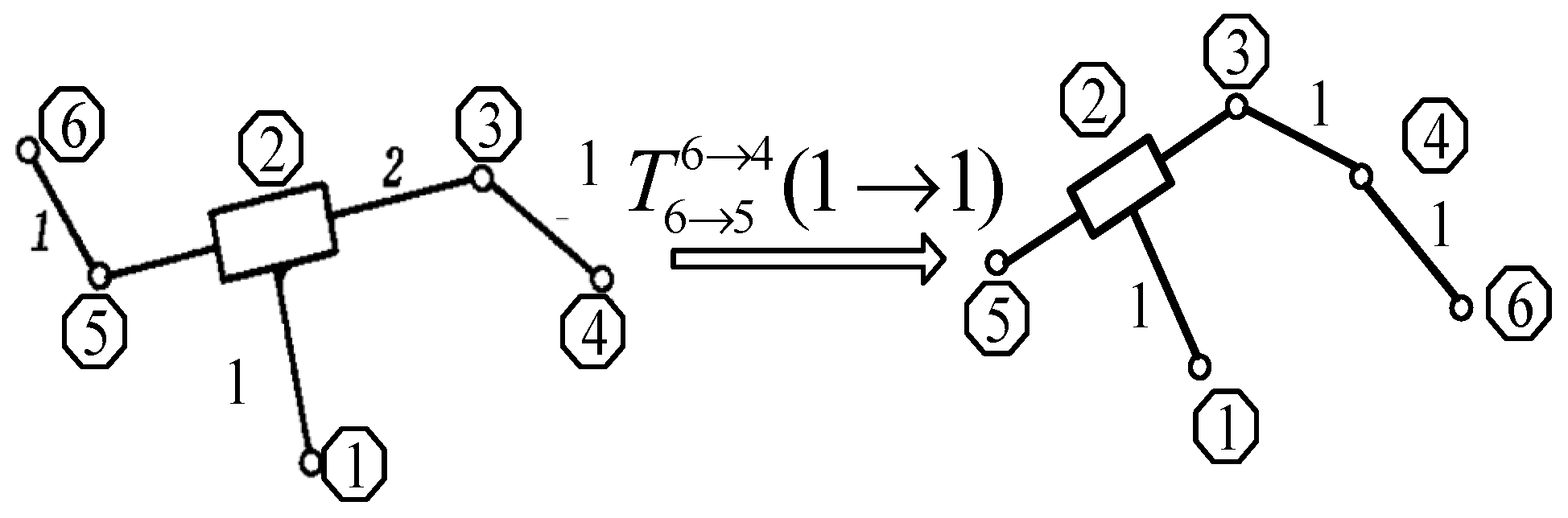
- Translocation operation
- (2)
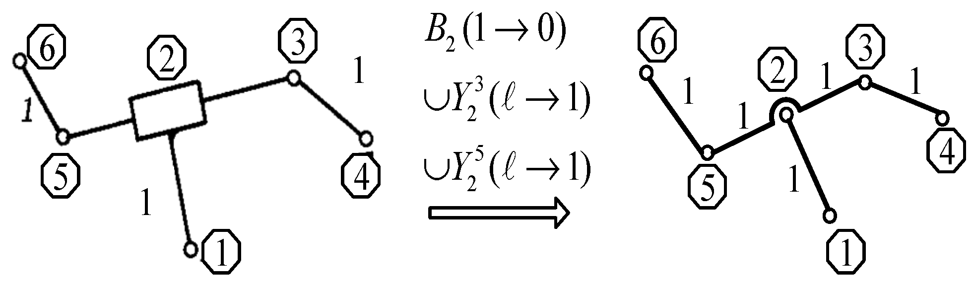
- Inversion operation
- (3)
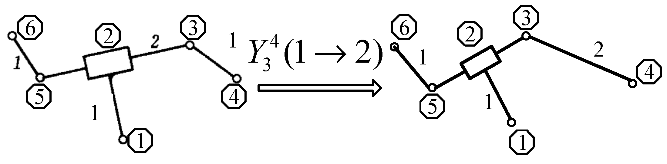
- Duplication operation
3. Configuration Synthesis Method of the Metamorphic Mechanism
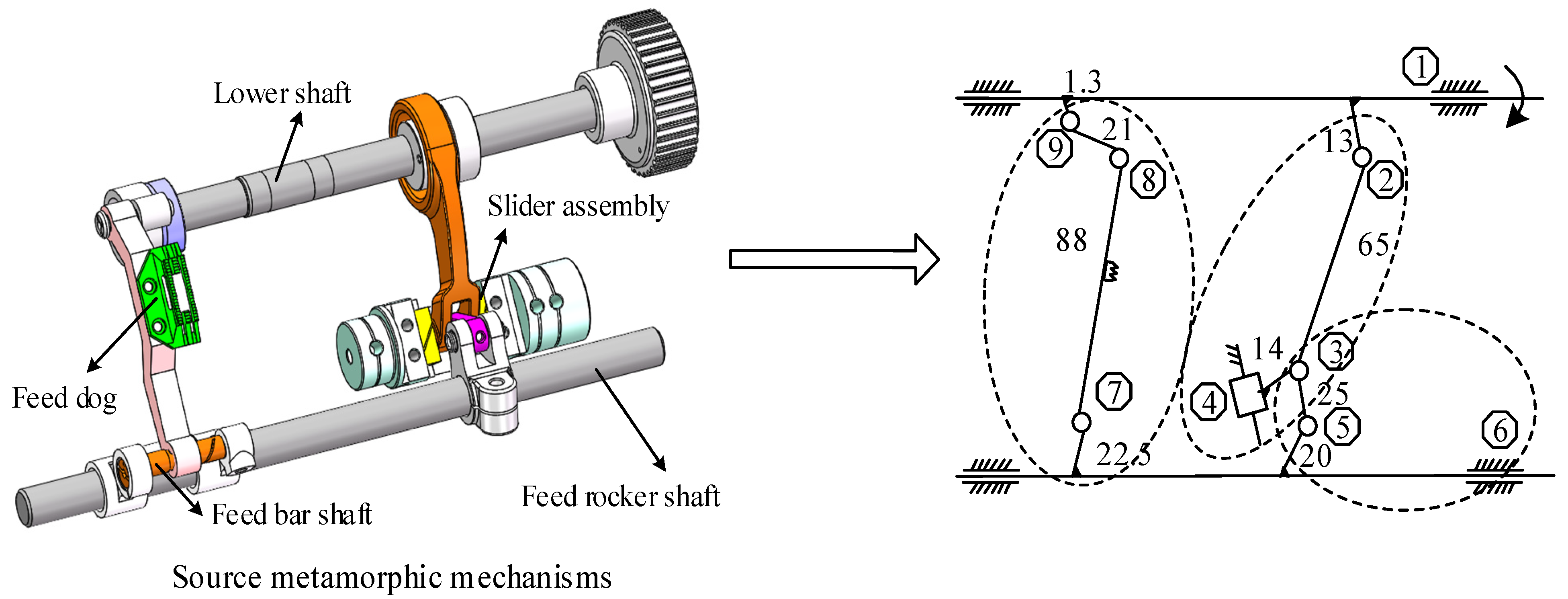
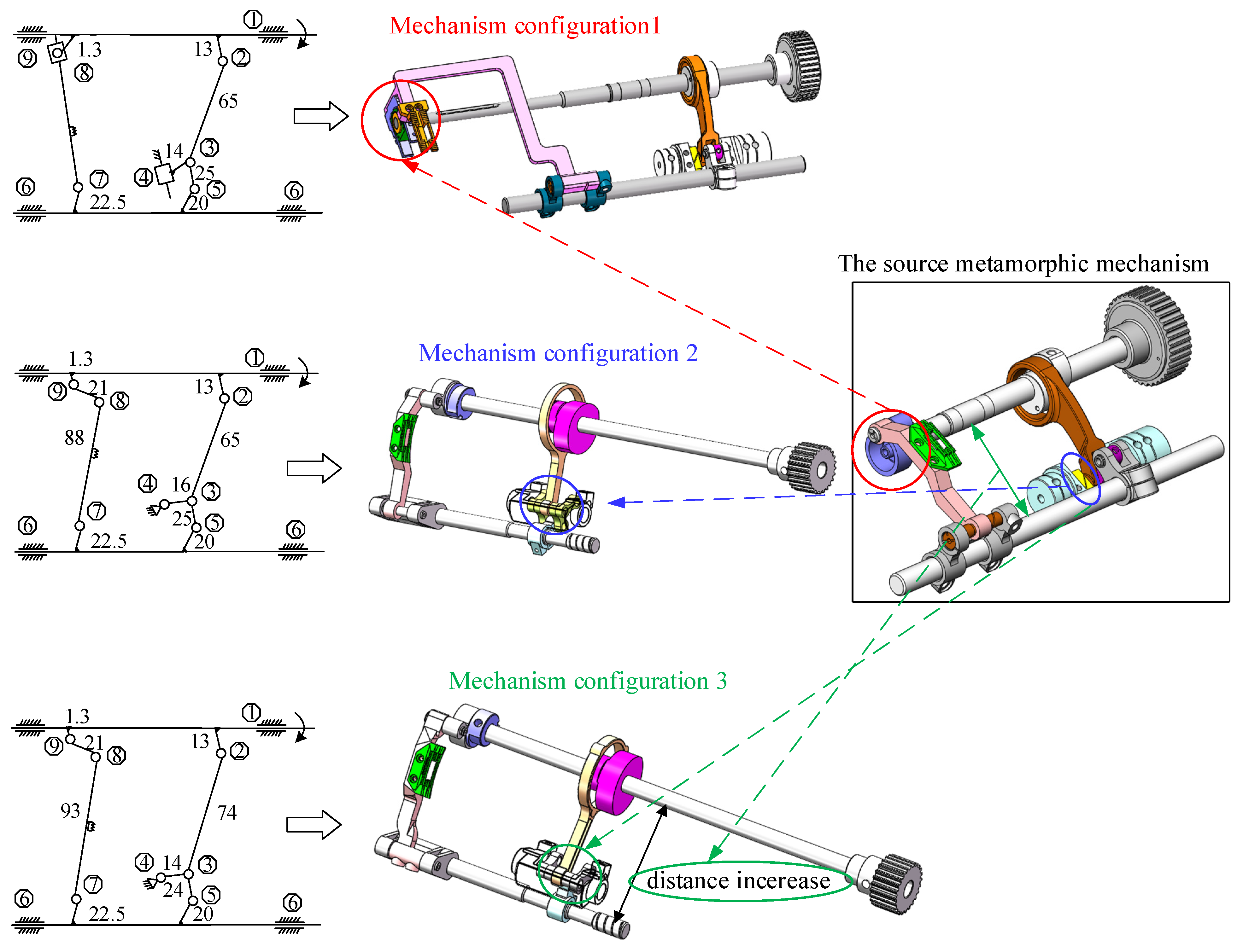
3.1. Source Metamorphic Mechanism Disintegration
3.2. Constraint Functions of Metamorphic Elements
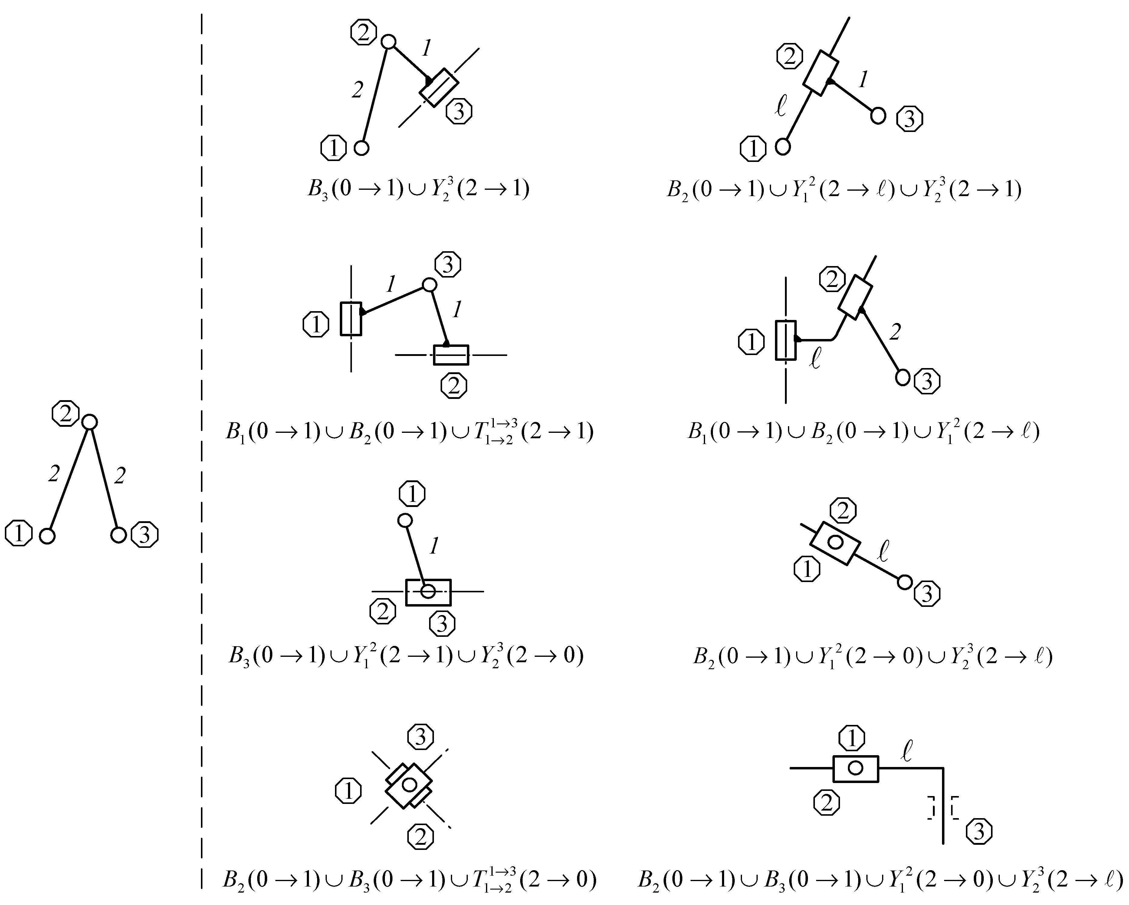
3.3. Metamorphic Element Configuration Scheme
3.4. Configuration Synthesis of Metamorphic Mechanism
- (1)
- The aggregated two metamorphic elements have the same motion directions.
- (2)
- The characteristics of aggregated kinematic pairs are consistent.
- (3)
- When the metamorphic elements are aggregated, the kinematic pairs of a metamorphic element fail to connect to the same metamorphic element.
- (4)
- The relative position of other kinematic pairs remains constant.
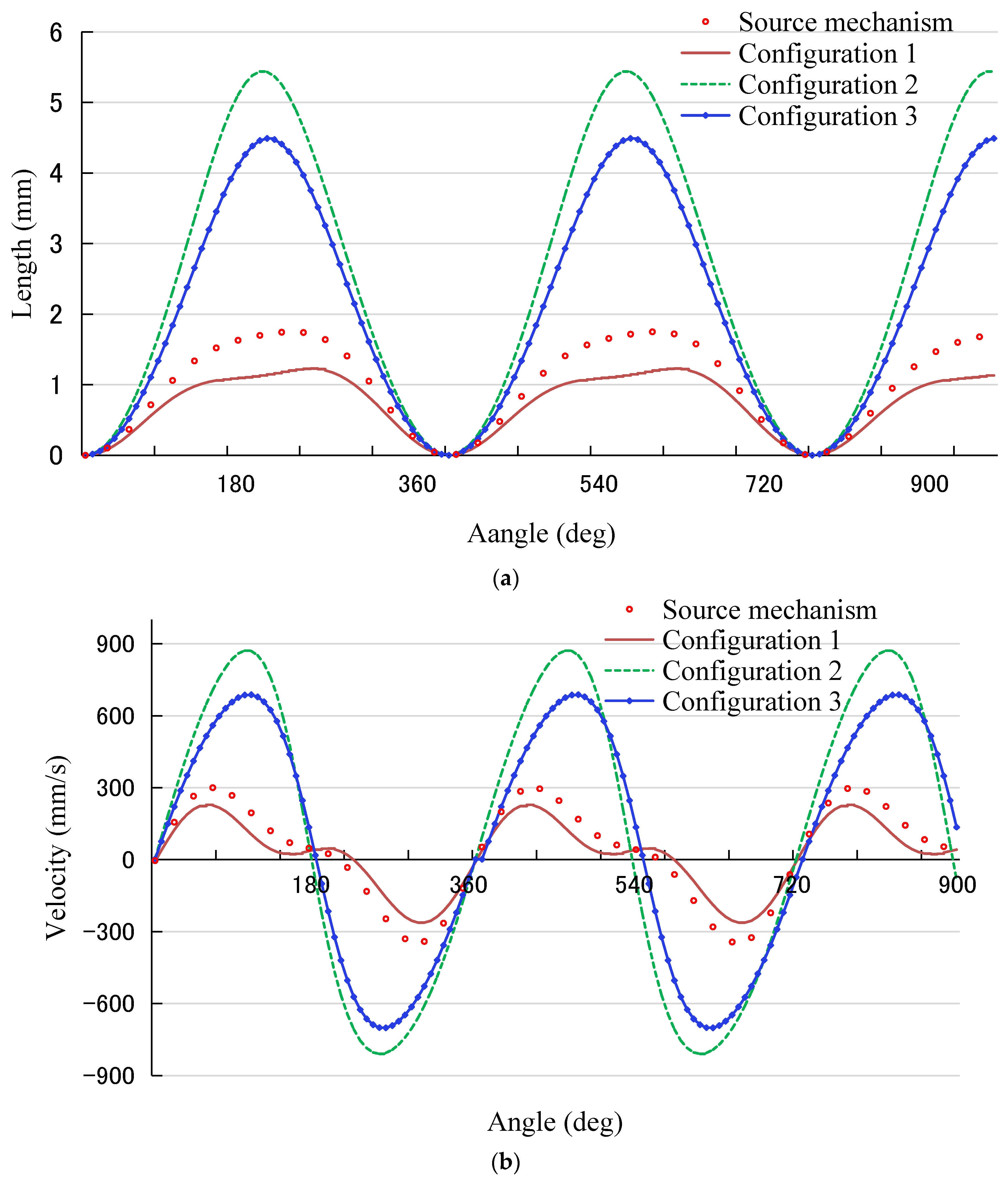
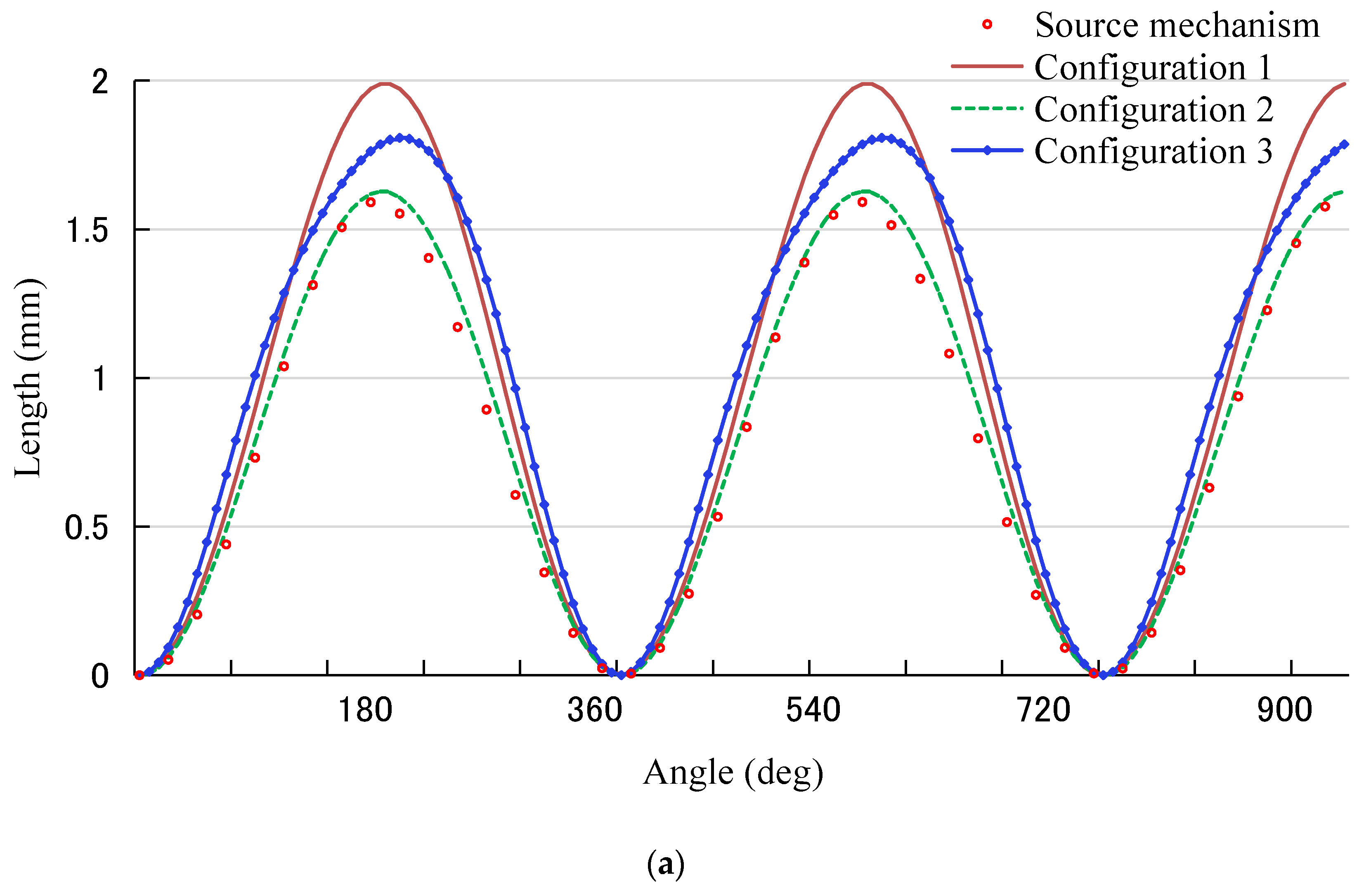
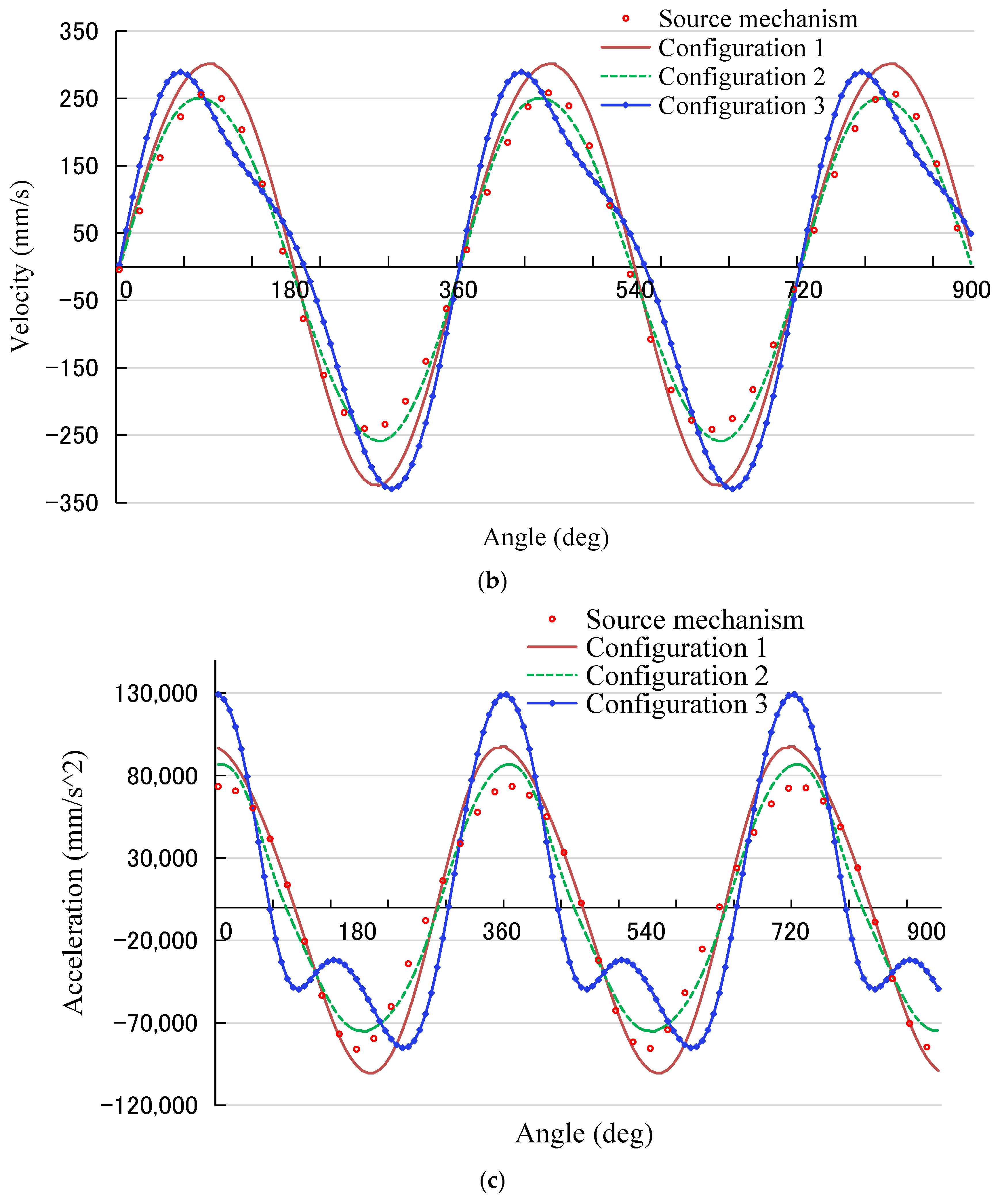
4. Comparison of the Mechanism Configurations
5. Conclusions
- (1)
- Metamorphic element mode consisting of kinematic pair and kinematic size, and a three-layer coupling relationship of the metamorphic mechanism, metamorphic element, kinematic pair and kinematic size are established. An optimization of the variation modes of the metamorphic element, such as translocation, inversion and duplication, are performed successfully.
- (2)
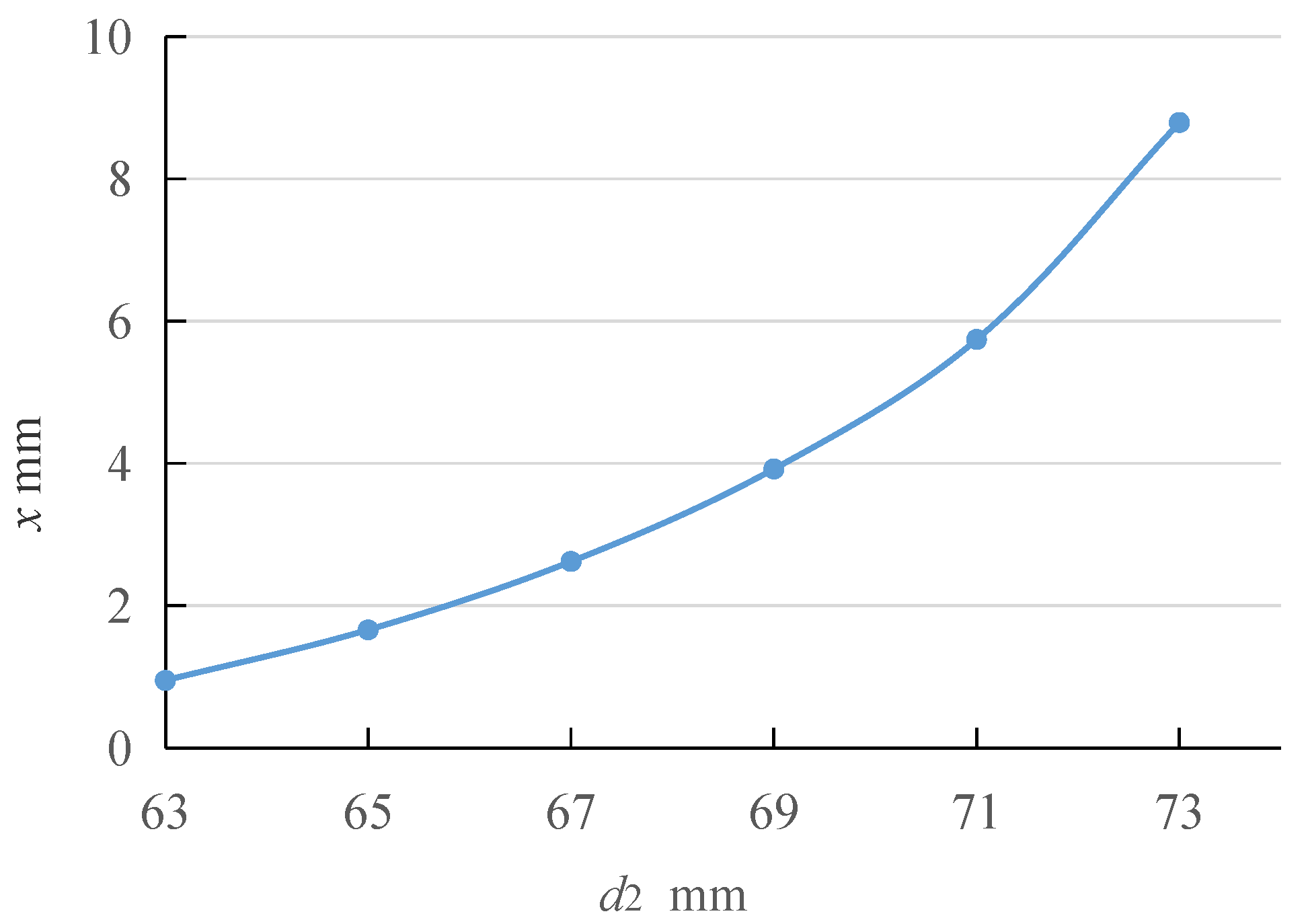
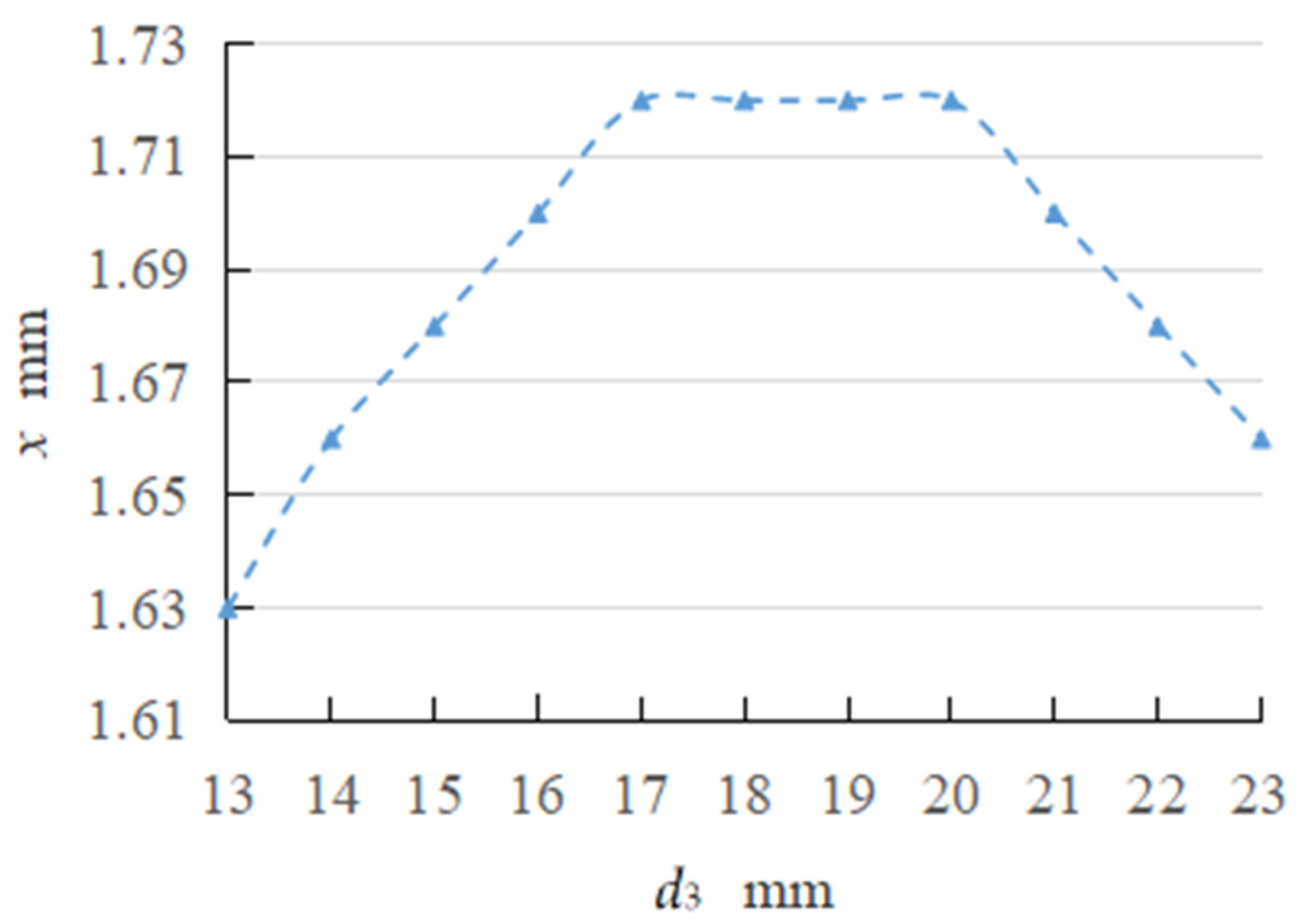
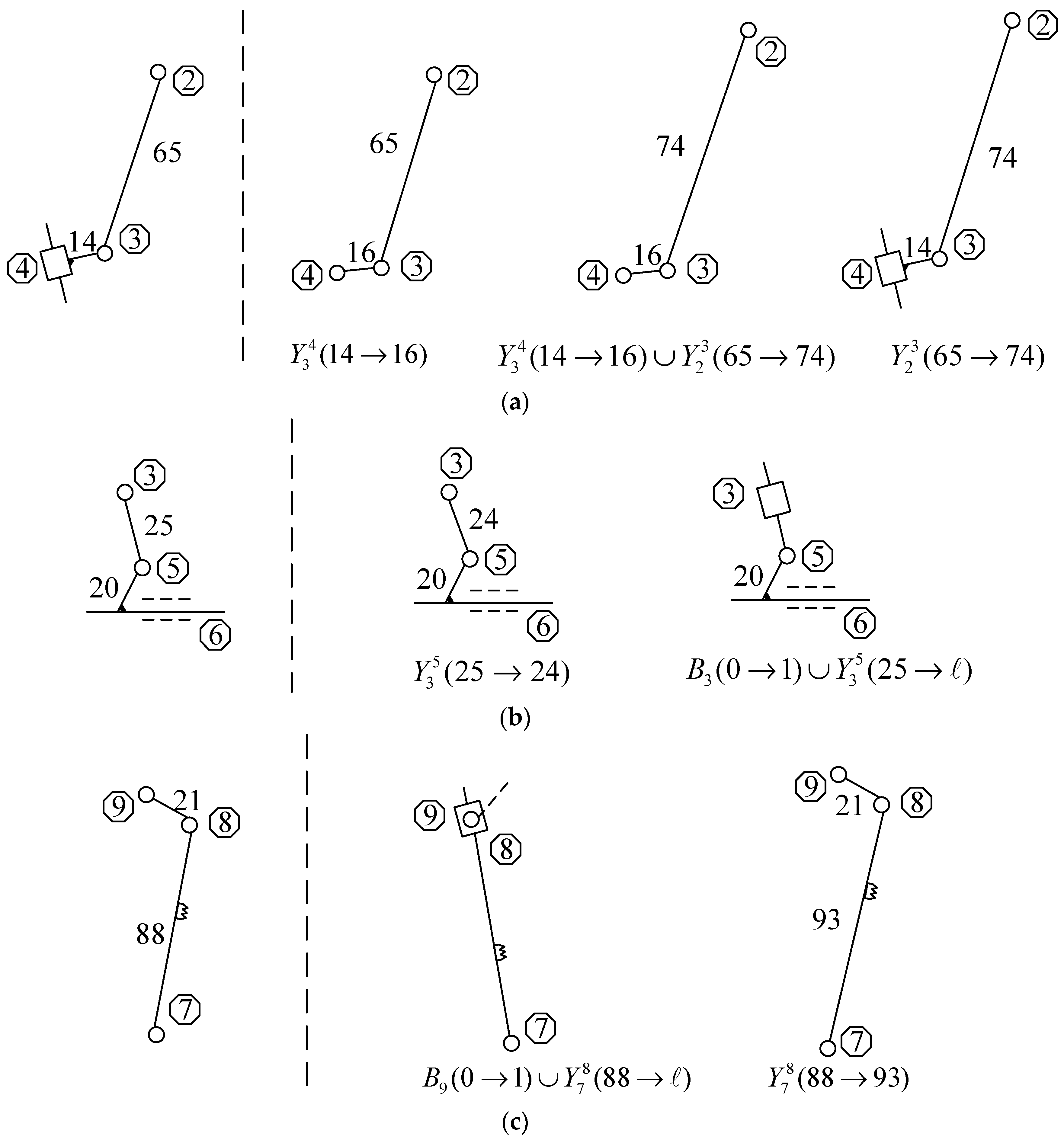
- Feed mechanism is decomposed into three kinds of metamorphic elements of Assur group II. The constraint equations of metamorphic elements and their influence relationships among three kinematic sizes and the displacement of the feed dog are revealed. An interesting finding is that the displacement x is proportional to the kinematic size d2, trapezoidal to the kinematic size d3, and parabolic to the kinematic size d6. The value ranges of the three kinematic sizes are obtained, with d2 = (5, 73) mm, d3 = (13, 17) mm, and d6 = (23, 25) mm, respectively.
- (3)
- Configuration schemes of three metamorphic elements and three mechanism configurations of the feed mechanism are synthesized successfully.
- (4)
- The upward and downward displacement of mechanism configuration 1 is suitable for sewing thick material with the largest value of 1.99 mm, which is one-fifth higher than that of the source mechanism. Forward and backward displacement of mechanism configuration 2 is 1.7 times higher than the source mechanism counterpart, as well as relatively larger that configuration 3. Regarding global movements, mechanism configuration 2 exhibits better stability behavior, which is more suitable for efficient and high-speed places, verifying that the proposed mechanism is better than the source mechanism.
- (5)
- This work provides guidance for the design of the lockstitch sewing machine with differently functional requirements. In our future studies, the dynamic behavior of the three proposed configurations and the source mechanism will be further investigated by manufacturing verification machines, and applying the method to the design of more types of sewing equipment.
Author Contributions
Funding
Data Availability Statement
Conflicts of Interest
References
- Dai, J.S.; Jones, J.R. Matrix Representation of Topological Changes in Metamorphic Mechanisms. J. Mech. Des. 2005, 127, 837–840. [Google Scholar] [CrossRef]
- Valsamos, C.; Moulianitis, V.; Aspragathos, N. Index based optimal anatomy of a metamorphic manipulator for a given task. Robot. Comput. Integr. Manuf. 2012, 28, 517–529. [Google Scholar] [CrossRef]
- Zhang, W.; Wu, T.; Ding, X. An optimization method for metamorphic mechanisms based on multidisciplinary design optimization. Chin. J. Aeronaut. 2014, 27, 1612–1618. [Google Scholar] [CrossRef] [Green Version]
- Tian, H.-B.; Ma, H.-W.; Ma, K. Method for configuration synthesis of metamorphic mechanisms based on functional analyses. Mech. Mach. Theory 2018, 123, 27–39. [Google Scholar] [CrossRef]
- Carbonari, L.; Callegari, M.; Palmieri, G.; Palpacelli, M.C. A new class of reconfigurable parallel kinematic machines. Mech. Mach. Theory. 2014, 74, 173–183. [Google Scholar] [CrossRef]
- Aimedee, F.; Gogu, G.; Dai, J.; Bouzgarrou, C.; Bouton, N. Systematization of morphing in reconfigurable mechanisms. Mech. Mach. Theory 2016, 96, 215–224. [Google Scholar] [CrossRef]
- Wang, R.; Liao, Y.; Dai, J.S.; Chen, H.; Cai, G. The isomorphic design and analysis of a novel plane-space polyhedral metamorphic mechanism. Mech. Mach. Theory 2019, 131, 152–171. [Google Scholar] [CrossRef]
- Li, S.; Dai, J.S. Structure Synthesis of Single-Driven Metamorphic Mechanisms Based on the Augmented Assur Groups. J. Mech. Robot. 2012, 4, 031004. [Google Scholar] [CrossRef]
- Kuo, C.-H.; Yan, H.-S.; Kuo, C.H. On the Mobility and Configuration Singularity of Mechanisms with Variable Topologies. J. Mech. Des. 2007, 129, 617–624. [Google Scholar] [CrossRef]
- Yan, H.-S.; Kang, C.-H. Configuration synthesis of mechanisms with variable topologies. Mech. Mach. Theory 2009, 44, 896–911. [Google Scholar] [CrossRef]
- Goel, A.K.; Vattam, S.; Wiltgen, B.; Helms, M. Cognitive, collaborative, conceptual and creative-four characteristics of the next generation of knowledge-based CAD systems: A study in biologically inspired design. Comput. Aided Design. 2012, 44, 879–900. [Google Scholar] [CrossRef]
- Chen, Y.; Chai, W.H. Bifurcation of a special line and plane symmetric Bricard linkage. Mech. Mach. Theory 2011, 46, 515–533. [Google Scholar] [CrossRef]
- Kong, X.; Pfurner, M. Type synthesis and reconfiguration analysis of a class of variable-DOF single-loop mechanisms. Mech. Mach. Theory 2015, 85, 116–128. [Google Scholar] [CrossRef]
- Lopez-Custodio, P.C.; Dai, J.S.; Rico, J.M. Branch Reconfiguration of Bricard Linkages Based on Toroids Intersections: Line-Symmetric Case. J. Mech. Robot. 2018, 10, 031003. [Google Scholar] [CrossRef]
- Zhang, L.; Wang, D.; Dai, J.S. Biological Modeling and Evolution Based Synthesis of Metamorphic Mechanisms. J. Mech. Des. 2008, 130, 072303. [Google Scholar] [CrossRef]
- Zhang, L.; Dai, J.S. Reconfiguration of Spatial Metamorphic Mechanisms. J. Mech. Robot. 2009, 1, 011012. [Google Scholar] [CrossRef]
- Gan, D.; Dai, J.S.; Dias, J.; Seneviratne, L. Reconfiguration and Static Joint Force Variation of a 3rRPS Metamorphic Parallel Mechanism with 3R and 1T2R Motion. Mech. Mach. Theory 2016, 36, 213–222. [Google Scholar] [CrossRef]
- Galletti, C.; Fanghella, P. Single-loop kinematotropic mechanisms. Mech. Mach. Theory 2001, 36, 743–761. [Google Scholar] [CrossRef]
- Padey, M.D.; Zhang, X.F. System reliability analysis of the robotic manipulator with random joint clearances. Mech. Mach. Theory 2012, 58, 137–152. [Google Scholar]
- Yim, N.H.; Kang, S.W.; Kim, Y.Y. Topology Optimization of Planar Gear-Linkage Mechanisms. J. Mech. Des. 2019, 141, 032301. [Google Scholar] [CrossRef]
- Ye, W.; Fang, Y.; Guo, S. Reconfigurable parallel mechanisms with planar five-bar metamorphic linkages. Sci. China Technol. Sci. 2017, 57, 210–218. [Google Scholar] [CrossRef]
- Nokleby, S.B.; Podhorodeski, R.P. Optimization-Based Synthesis of Grashof Geared Five-Bar Mechanisms. J. Mech. Des. 2001, 123, 529–534. [Google Scholar] [CrossRef]
- Ruggiu, M.; Kong, X. Mobility and kinematic analysis of a parallel mechanism with both PPR and planar operation modes. Mech. Mach. Theory 2012, 55, 77–90. [Google Scholar] [CrossRef]
- Balli, S.S.; Chand, S. Synthesis of a five-bar mechanism with variable topology for motion between extreme positions (SYNFBVTM). Mech. Mach. Theory 2001, 36, 1147–1156. [Google Scholar] [CrossRef]
- Balli, S.S.; Chand, S. Synthesis of a planar seven-link mechanism with variable topology for motion between two dead-center positions. Mech. Mach. Theory 2003, 38, 1271–1287. [Google Scholar] [CrossRef]
- Zhang, K.; Dai, J.S.; Fang, Y. Topology and Constraint Analysis of Phase Change in the Metamorphic Chain and Its Evolved Mechanism. J. Mech. Des. 2010, 132, 121001. [Google Scholar] [CrossRef]
- Plitea, N.; Lese, D.; Pisla, D.; Vaida, C. Structural design and kinematics of a new parallel reconfigurable robot. J. Robot. Comput. Integr. Manuf. 2013, 23, 219–235. [Google Scholar] [CrossRef]
- Kang, X.; Feng, H.; Dai, J.S.; Yu, H. High-order based revelation of bifurcation of novel Schatz-inspired metamorphic mechanisms using screw theory. Mech. Mach. Theory 2020, 152, 103931. [Google Scholar] [CrossRef]
- Nurahmi, L.; Caro, S.; Wenger, P.; Schadlbauer, J.; Husty, M. Reconfiguration analysis of a 4-RUU parallel manipulator. Mech. Mach. Theory 2016, 96, 269–289. [Google Scholar] [CrossRef] [Green Version]
- Kang, X.; Lei, H.; Li, B. Multiple bifurcated reconfiguration of double-loop metamorphic mechanisms with prismatic joints. Mech. Mach. Theory 2022, 178, 105081. [Google Scholar] [CrossRef]
- Sun, H.; Ge, W.J. Theory of Machines and Mechanisms; Higher Education Press: Beijing, China, 2021; ISBN 9787040555899. [Google Scholar]


| Pa | 0 | 1 | 2 | 3 |
| Meaning | Revolute pair | Prismatic pair | Planar and planar pair | Planar high pair |
| Mechanism Configuration | Source Mechanism | Expression | Configuration of Metamorphic Element |
|---|---|---|---|
| 1 | 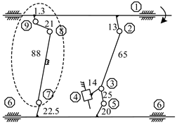 |  | |
| 2 |  | 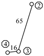 | |
| 3 |  | 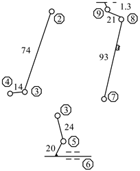 |
Publisher’s Note: MDPI stays neutral with regard to jurisdictional claims in published maps and institutional affiliations. |
© 2022 by the authors. Licensee MDPI, Basel, Switzerland. This article is an open access article distributed under the terms and conditions of the Creative Commons Attribution (CC BY) license (https://creativecommons.org/licenses/by/4.0/).
Share and Cite
Zhang, L.; Liu, Y.; Zhang, Y. An Improved Metamorphosis-Based Scheme of Feed Mechanism Using Configuration Synthesis. Processes 2022, 10, 2487. https://doi.org/10.3390/pr10122487
Zhang L, Liu Y, Zhang Y. An Improved Metamorphosis-Based Scheme of Feed Mechanism Using Configuration Synthesis. Processes. 2022; 10(12):2487. https://doi.org/10.3390/pr10122487
Chicago/Turabian StyleZhang, Li, Yang Liu, and Yongju Zhang. 2022. "An Improved Metamorphosis-Based Scheme of Feed Mechanism Using Configuration Synthesis" Processes 10, no. 12: 2487. https://doi.org/10.3390/pr10122487