Abstract
Lithium metal batteries are one of the more promising replacements for lithium-ion batteries owing to their ability to reach high energy densities. The main problem limiting their commercial application is the formation of dendrites, which significantly reduces their durability and renders the batteries unsafe. In the present work, we used a single-ion conducting gel polymer electrolyte based on a poly(ethylene-ran-butylene)-block-polystyrene (SEBS) block copolymer, which was functionalized with benzenesulfonylimide anions and plasticized by a mixture of ethylene carbonate and dimethylacetamide (SSEBS-Ph-EC-DMA), with a solvent uptake of 160% (~12 solvent molecules per one functional group of the membrane). The SSEBS-Ph-EC-DMA electrolyte exhibits an ionic conductivity of 0.6 mSm∙cm−1 at 25 °C and appears to be a cationic conductor (TLi+ = 0.72). SSEBS-Ph-EC-DMA is electrochemically stable up to 4.1 V. Symmetrical Li|Li cells; further, with regard to SSEBS-Ph-EC-DMA membrane electrolytes, it showed a good performance (~0.10 V at first cycles and <0.23 V after 700 h of cycling at ±0.1 mA∙cm−2 and ±0.05 mAh∙cm−2). The LiFePO4|SSEBS-Ph-EC-DMA|Li battery showed discharge capacity values of 100 mAh∙g−1 and a 100% Coulomb efficiency, at a cycling rate of 0.1C.
1. Introduction
The switch to carbon-free energy and the desire to improve urban air quality is significantly related to the development of scientific and technological progress in the field of electrochemical energy storage [1,2]. The use of electric vehicles can significantly reduce greenhouse gas emissions and air pollution when compared to internal combustion engines, thus the increased use of them is becoming a key element of vehicle development strategies. At the same time, energy companies are installing large power plants based on renewable energy sources, such as wind, solar, and hydro power plants, etc. The demand for lithium-ion batteries that are used as energy sources is, inevitably, growing. This is because they are used in electric and hybrid vehicles, as well as in stationary energy storage units at renewable energy power plants [3,4].
In order to satisfy higher energy requirements, batteries with a lithium metal anode are a promising solution for the next generation of high energy density applications. Lithium is considered the ideal anode for high energy batteries due to its high, theoretical specific capacity (3860 mAh∙g−1) and its low electrochemical potential (−3.04 V vs. standard hydrogen electrode), which is higher than the current graphite (372 mAh∙g−1) and silicon-based (1956–3570 mAh∙g−1) anodes for lithium-ion batteries [5,6,7]. The main problems limiting the commercial application of such batteries is the uncontrollable growth of Li dendrites during its deposition, the unstable electrode/electrolyte interface, and the low Coulombic efficiency caused by inefficient solid electrolyte interphase (SEI) formation.
There are several models that explain the mechanism of dendrite formation [5,8,9,10]. According to the space charge theory, proposed by Chazalviel, there is a concentration gradient of cations in the electrolyte between the two electrodes when a direct current is applied. Depletion of cations near the anode surface at a high current density disturb electroneutrality at the electrode surface, which leads to the formation of local space charge and the formation of branched dendrites [11]. A quantitative description of this model, which showed a concentration gradient across the cell with a small gap between the electrodes, was proposed by Brissot et al. [12]. According to the proposed models, increasing the time at which dendrites grow is possible by increasing the initial concentration of cations in the electrolyte through the use of highly concentrated electrolytes [13]. Moreover, this therefore reduces local current density by using 3D current collectors or conducting structures—or increasing the Li+ transference numbers in the electrolyte—by utilizing single-ion conducting electrolytes, such as in, for example, cation-exchange membranes [14,15].
In cation-exchange membranes, anions are covalently bound to the polymer matrix. Such electrolytes possess only cationic conductivity and are characterized by transference numbers close to unity. In order to maximize the mobility of cations, functional groups are often localized on the side branches of the main polymer chain. Among recent works in the field of development of single-ion conductors for application in batteries, cation-exchange membranes containing the functional sulfonylimide groups R-SO2N−SO2-X tend to dominate. This is because their bulk conjugated structure can effectively delocalize the negative charge [16,17,18,19]. Such a functional groups in the polymer matrix reduces the dissociation energy with Li+ cations due to high charge delocalization and the facilitating of ionic transport. The negative charge distribution in R-SO2N−SO2-X can be further improved by introducing various electronegative groups such as −CF3, −Ph, or −PhCF3 [20,21,22,23]. Two methods for obtaining polymers containing a sulfonylimide group have been described in the literature: polymerization of a previously functionalized monomer [21,23] and the functionalization of the polymer matrix [18,24]. However, the first method is quite complicated due to both the need for a functionalized monomer and the difficulty of adjusting the polymerization conditions.
The solvation of such membranes via organic aprotic solvents provides high values of ionic conductivity, which can reach values of up to 10−4–10−3 S∙cm−1 at room temperature [20,25]. Organic carbonates used in lithium-ion batteries are most commonly chosen for this purpose. Usually, polar aprotic solvents with a high dielectric constant (ethylene or propylene carbonate, etc.) are also characterized by high viscosity and do not ensure fast ion transport. Therefore, mixtures of solvents with a high dielectric constant and low viscosity, such as dimethyl carbonate, diethyl carbonate, etc., are used as the diluent component. However, membrane solvation with conventional organic carbonates often does not ensure sufficient ionic conductivity [16]. There are several reports regarding the use of N,N-dimethylacetamide (DMA) with a high dielectric permittivity (ε = 37.8) [26] as a stabilizing additive [27,28], or as an individual solvent in lithium-ion batteries [26,29]. However, DMA is characterized by low chemical stability in contact with alkali metals [29,30]; further, the use of mixtures of DMA with ethylene carbonate increases electrolyte stability by the forming of a protective film that prevents DMA from interacting with the metal [31]. Despite the evident promising performance of this research direction, there are few works devoted to the successful application of ion-exchange membranes in batteries with a lithium anode, which indicates the need to continue this research.
Thus, the aim of the present work was to study the properties of a gel-polymer electrolyte based on a commercially available poly(ethylene-ran-butylene)-block-polystyrene polymer, functionalized with a benzenesulfonylimide group in lithium form and solvated by the mixture of ethylene carbonate and N,N-dimethylacetamide. The transference numbers, as well as the thermal and electrochemical stability of SSEBS-Ph-EC-DMA, were characterized for the first time. Furthermore, the stable operation of Li|Li and LFP|Li cells with SSEBS-Ph-EC-DMA electrolyte was shown.
2. Materials and Methods
In this work we used triethylamine (≥99%, Merck, Darmstadt, Germany), benzenesulfonyl chloride (99%, Merck, Darmstadt, Germany), acetonitrile (HPLC-R, Biosolve, Dieuze, France), aqueous ammonia (HP, Chimmed, Moscow, Russia), ethylene carbonate (≥99%, Merck, Darmstadt, Germany), N,N-dimethylacetamide (99.8%, anhydrous, Merck, Darmstadt, Germany), dichlorethane (HP, Chimmed, Moscow, Russia), polystyrene-block-poly(ethylene-ran-buthulene)-block-polystyrene powder, SEBS (Mw~118 kDa contains >0.03% antioxidant as inhibitor, Sigma-Aldrich Chemie GmbH, St. Louis, USA), cyclohexane (HP, Chimmed, Moscow, Russia), chlorosulfonic acid (99%, Sigma-Aldrich Chemie GmbH, Switzerland), methanol (HPLC, Lab-scan, Lodz, Poland), porous polypropylene film, and LiClO4 (anhydrous, Merck, Darmstadt, Germany).
2.1. Membranes Production
The membranes were obtained according to a procedure previously described in the work [16]. For this purpose, the SEBS polymer was firstly dissolved in cyclohexane at +50 °C in order to obtain an 18 wt.% solution. The prepared solution was then placed on a Teflon wafer and maintained at room temperature for 30 min. The solution was coated on the Teflon substrate via a doctor blade technique. The resulting film was dried at 70 °C for 1 h in order to remove the cyclohexane. As a result, a film of SEBS polymer with a thickness of ~50 μm was obtained.
In order to obtain the membrane, the SEBS film was first sulfonated in a 3 vol.% chlorosulfonic acid solution in dichloroethane dried over 3Å molecular sieves. Sulfonation time was 30 min. The resulting film contained polystyrene that was functionalized with R-SO2Cl and R-SO3H groups (Figure 1). In order to obtain the cation-exchange membrane with benzenesulfonylimide groups (SSEBS-Ph), the R-SO2Cl groups were firstly converted to sulfonamide R-SO2NH2 (SSEBS-NH2) via a treatment with an aqueous ammonia cooled to +4 °C for 2 h. The resulting SSEBS-NH2 films were washed several times with deionized water and converted to H+ form by soaking in 0.1M hydrochloric acid solution. Then, the membranes were washed with deionized water till they reached a neutral pH and were then dried at +50 °C within a vacuum for 2 h.
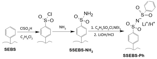
Figure 1.
Scheme for obtaining the SSEBS-Ph membrane.
In order to synthesize membranes with benzenesulfonylimide functional groups via the Hinsberg reaction, the SSEBS-NH2 membranes were placed in a solution containing triethylamine and benzenesulfonyl chloride in anhydrous acetonitrile. The concentrations of benzenesulfonyl chloride and triethylamine were 1.5M and 0.5M, respectively. The reaction was performed at room temperature without air contact. After 3 h the membranes were washed several times with acetonitrile, then with water, and then placed in 0.1M solutions of LiOH or HCl in order to be converted into Li+ or H+ form, respectively, for 3 h with a threefold replacement of the solution. The obtained membranes were dried at +50 °C within a vacuum for 2 h.
2.2. Gel-polymer Electrolyte
In order to obtain the plasticized polymer electrolytes, the obtained dry SSEBS-Ph membranes in Li+ form were placed in a dry argon-filled glove box and soaked in a solution containing ethylene carbonate and N,N-dimethylacetamide (EC-DMA, V:V = 1:1). The membranes were soaked in this solvent over activated molecular sieves (3Å) for one day. The polymer electrolyte work was performed in an argon-filled glove box with O2 and H2O content that were both less than 5 ppm.
2.3. Membrane’s Characterization
The ion-exchange capacity (mmol∙g−1) of the obtained SSEBS-NH2 and SSEBS-Ph membranes were measured via acid-base titration. For this purpose, dry membranes in H+ form were soaked in 0.5M NaCl for one day under constant stirring. Then, the solution was titrated by ~0.01M NaOH. The exact concentration of sodium hydroxide was determined by titrating 1 mL of a 0.1M HCl solution, which was prepared by diluting the standard titer. The equivalence point was determined by the color change in the universal indicator. IEC values were calculated by Equation (1):
where and is the concentration and volume of sodium hydroxide taken for titration, expressed in mol∙L−1 and L, respectively; further, mdry is the mass of dry membrane (g) and Vsolution is the volume of solution above the membrane (L).
The IR spectra of the dry samples of SSEBS-NH2, SSEBS-Ph, and solvated electrolyte SSEBS-Ph-EC-DMA were obtained using a Thermo Nicolet iS5 IR spectrometer (Thermo Fisher Scientific, USA) with a Specac Quest attachment in the attenuated total reflection (ATR) mode with a diamond crystal in the frequency range 500–4000 cm−1.
The composition of the SSEBS-Ph membrane in H+ form, as well as the SSEBS-NH2 were calculated via elemental CHNS analysis using a EuroVector EA3000 (EuroVector, Pavia, Italy).
The degree of solvation of the membranes by the EC-DMA mixture was determined as the ratio of the number of solvent molecules to the number of all functional groups of the membranes, as based on the IEC and mass increase after soaking it in the solvent. This was achieved by assuming that the composition of the immersed solvents did not differ from the initial one.
The X-ray diffraction (XRD) analysis was carried out with the use of a Rigaku D/MAX 2200 diffractometer (CuKα, Rigaku, Tokyo, Japan).
Furthermore, the differential scanning calorimetry of the solvated membrane was performed on a NETZSCH STA 449F1 (NETZSCH, Selb, Germany) within aluminum crucibles under a helium atmosphere with a flow rate of 20 mL∙min−1 in the temperature range −100–+130 °C with a heating rate at 10 °C min−1.
2.4. Electrochemical Characterization
The ionic conductivity of the polymer electrolytes in Li+ form, plasticized by EC-DMA, was studied by impedance spectroscopy in the temperature range of −20... +50 °C within an argon atmosphere. A Binder MKF115 climate chamber was used to set the necessary temperature. The temperature dependence of the ionic conductivity of the studied samples followed the Arrhenius equation and was linear in the logσ − 1000/T coordinates. The measurements were performed using an Elins Z-1500J AC bridge (Elins, Chernogolovka, Russia), in the frequency range of 2 MHz–10 Hz on symmetrical CR2032 coin-type cells Al|SSEBS-Ph-EC-DMA|Al [32]. The resistivity was determined from the cutoff on the active resistivity axis in a Nyquist plot in the high temperature region, or by the extrapolation of the half-circle on the active resistivity axis using the ZView 4 software. The activation energy of ionic conductivity was calculated using the Arrhenius equation from the slope of the linear section in the coordinates logσ − 1000/T.
The Li+ transference number was evaluated by the Bruce–Vincent method [33] in a symmetrical Li|SSEBS-Ph-EC-DMA|Li coin-type cell using Elins P-20X8 (Elins, Chernogolovka Russia). The cell was polarized by a direct current (△V = 0.01 V). The current value before direct current polarization (I0) was also measured. The current value in the steady state (Iss) was obtained by extrapolation to infinite time and the experimentally recorded chronoamperometry curve. The interfacial resistance was measured before (R0) and after (Rf) polarization via the impedance in the frequency range of 500 kHz to 10 mHz. TLi+ was calculated using the following Equation (2):
The electrochemical stability window (vs. Li/Li+) of the obtained polymer electrolytes based on SSEPS-Ph-Li+, was determined via linear voltammetry using an Elins P-20X8 multi-channel potentiostat-galvanostat (Elins, Russia). The membrane sample was placed between the stainless-steel electrode (SS, as the working electrode) and the lithium electrode (as the counter electrode and reference electrode). It was then assembled in a CR2032 coin-type cell. The potential scans were performed in the range of 0 to 5.5 V (vs. Li/Li+) at a sweep rate of 1.0 mV∙s−1. Cyclic voltammetry was performed in the potential range of 2.5–4.1 V in SS|Li cells at a sweep rate of 1.0 mV∙s−1 for 50 cycles.
In order to assess the stability of the obtained polymer electrolytes against lithium metal, we performed galvanostatic cycling at a current density of ±0.1 mA∙cm−2 in the symmetrical Li|Li coin-type CR2032 cell on a multi-channel potentiostat-galvanostat Elins P-20X8 (Elins, Russia). The time per cycle was 1 h (cut-off capacity was ±0.05 mAh∙cm−2). Before the experiments, the lithium disks were preliminarily cleaned of lithium oxide and carbonate.
In order to evaluate the possibility of using the investigated polymer electrolytes in real lithium metal batteries, we checked coin-type cells with a lithium metal anode and a composite of a LiFePO4@C (LFP) cathode, which was obtained by the sol-gel method, as well as through sucrose as a carbon coating source according to the procedure described in [34]. In order to prepare the positive electrode, an LFP composite containing 5 wt% carbon was mixed with carbon black and a 5 wt% PVDF solution (MM = 1100 kDa) in N-methyl-2-pyrrolidone (LFP: carbon black: binder ratio was 10:1:1). The resulting electrode paste was coated on 9 μm aluminum foil via a doctor-blade technique; in addition, the coating thickness of the wet cathode paste was 250 μm. The resulting cathode foil sheets were pre-dried at 100 °C for 1 h, then further kept at 120 °C within a vacuum for 24 h. Round electrodes with a diameter of 16 mm (2 cm2 area) were cut from the cathode foil. The electrochemical characterization of LFP|Li batteries was performed in coin-type cells CR2032. A cathodic disc, membrane sample, lithium metal (16 mm diameter), stainless-steel gasket, and wave spring were placed into a CR2032 battery shell, in sequence. The coin battery was sealed under 50 kg∙cm−2. Electrochemical tests were performed in the galvanostatic mode at 0.1C (17 mA∙g−1), 0.2C (34 mA∙g−1), 0.5C (85 mA∙g−1), and 1C (170 mA∙g−1) in the potential range of 2.5–4.1 V using an Elins P-20X8 multi-channel potentiostat-galvanostat (Elins, Russia). The required current was calculated based on the mass of active cathode material for each electrochemical cell.
Coulombic efficiency (CE, %) was calculated according to Equation (3):
where Qd and Qc are the charge and discharge capacity, respectively.
For the purposes of comparison, we also examined LFP|Li cells with the liquid electrolyte 1M LiClO4 in an ethylene carbonate—dimethyl carbonate mixture.
3. Results and Discussions
The sulfonation reaction of polystyrene with chlorosulfonic acid results in two main products: derivatives containing the sulfonic groups R-SO3− and the chlorosulfonyl group R-SO2Cl. In order to obtain a precursor for the Hinsberg reaction (SSEBS-NH2), the SEBS film after sulfonation—which contained R-SO2Cl and residual R-SO3H groups—was rapidly transferred into an aqueous ammonia solution that was cooled down to +4 °C. In addition to the fact that such a film may initially contain a small number of sulfonic groups—during the amination in the aqueous ammonia solution—some of the R-SO2Cl fragments may also interact with water. As a result of these processes, according to the acid-base titration, the SSEBS-NH2 membrane contains 0.6 mmol∙g−1 R-SO3H groups, and the total IEC of the SSEBS-Ph membrane was 1.49 mmol∙g−1.
The formation of R-SO2NH2 and benzenesulfonamide groups by the Hinzberg reaction (Figure 1) was confirmed by elemental CHNS analysis. The found molar ratio n(S)/n(N) 2.88 was close to the calculated data using titrimetric quantities of residual R-SO3- groups and R-SO2NH2 groups after the amination reaction (2.67).
Figure 2 shows the IR spectra of the SSEBS-NH2 polymer and the SSEBS-Ph membrane in Li+ form. In regard to the SSEBS-NH2 polymer, characteristic vibrations ν(N-H) in the region of 3500–3200 cm−1 are observed, as well as ν(N-S) and νas(SO2) for ArSO2NH2, which was characterized by non-intensive peaks at 907 and 1320 cm−1, respectively [35]. When the SSEBS-NH2 membrane is transferred to benzenesulfonylimide groups, the vibrations of νas(SO2) and ν(N-S) shift to the lower frequencies (Figure 2(2)). There are non-intensive broad peaks with a maximum at 3450 cm−1, as well as peaks at 1650 cm−1 (Figure 2) corresponding to the stretching ν(O-H) and bending δ(H-O-H) vibrations, respectively. This indicates the presence of moisture in the membrane. Further, this is explained by the fast moisture absorption by the membrane that is from the atmosphere. However, it is also known that cation-exchange membranes are able to keep a few water molecules, even after being heated at high temperatures [36]. When the membrane is immersed in solvents, it is absorbed by the membrane. In this case, characteristic peaks of these solvents are observed in the IR spectra. For example, one can observe vibrations ν(C=O) in the frequency range 1770−1790 cm−1 corresponding to EC or DMA at 1630 cm−1 (Figure 2(3)).
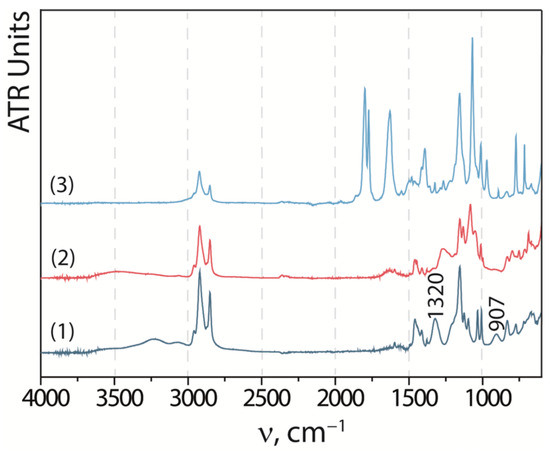
Figure 2.
IR spectra of SSEBS-NH2 (1), SSEBS-Ph (2), and SSEBS-Ph-EC-DMA membranes (3).
The solvated SSEBS-Ph membranes were ~160% swollen films with a thickness of ~95 μm and a solvation degree of ~12 solvent molecules per functional group of the membrane. According to X-ray diffraction analysis, SSEBS-Ph and SSEBS-Ph-EC-DMA are X-ray amorphous.
The temperature dependence of the ionic conductivity of SSEBS-Ph electrolytes that are solvated by EC-DMA follows the Arrhenius equation and straightens in logσ – 1000/T coordinates (Figure 3). The typical impedance hodographs at low and high temperatures are shown in Figure 4. At room temperature, ionic conductivity is 0.6 mSm∙cm−1, which exceeds values that are characteristic for the majority of polymer electrolytes and meets requirements for electrolytes in lithium metal batteries [25]. In regard to the temperature dependence of ionic conductivity, there is a kink at 10 °C, which corresponds to the phase transition of the electrolyte (Tmelting). It should be noted that with increasing temperatures the impedance spectra also changes (Figure 4). The presence of the phase transition is also confirmed by DSC data (Figure 3b). The DSC curve of the solvated membrane exhibits two endothermic peaks beginning at −58 °C and +8 °C (Figure 3b), which most likely corresponds to the melting of the DMA and EC-DMA solvent mixtures in the membrane pores, respectively. According to the curve of mass loss in the studied temperature range, there is no change in mass (up to 130 °C), which is associated with the high boiling points of EC and DMA. It can be concluded that the obtained electrolyte achieves high conductivity values at temperatures above 10 °C and can be successfully operated at elevated temperatures.
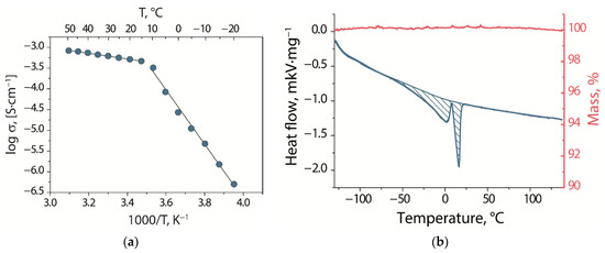
Figure 3.
(a) Temperature dependence of ionic conductivity and (b) DSC (blue line) and mass loss curve (red line) of SSEBS-Ph when solvated by EC-DMA.
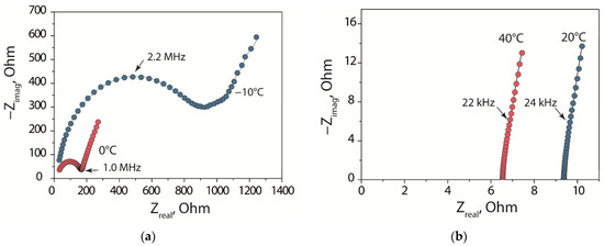
Figure 4.
Typical impedance spectra of the Al|SSEBS-Ph-EC-DMA|Al cell at (a) low and (b) high temperatures.
The absence of a sharp change in conductivity in the region of temperatures corresponding to endothermic effects is due to the fact that parts of the solvent localized at the pore walls do not freeze at these temperatures. This is because they participate in the solvation of lithium ions, which are located mainly within the thin Debye layer at the negatively charged pore walls [37]. Therefore, at these temperatures only the mixture of organic solvents localized in the center of the pore freezes in the membrane, which is achieved practically without Li+ ions. It is worth noting that increasing the temperature leads to a decrease in activation energy from 124 ± 4 to 13.1 ± 0.3 kJ∙mol−1. This is due to a simultaneous increase in the mobility of lithium ions and the gradual unfreezing of organic solvents in the pores of the membrane, as well as the appearance of new mobile current carriers. In the region of high temperatures, the entire solvent is in the liquid state and only the mobility of carriers will grow. At the same time, the last part of the solvent, which practically does not contain lithium ions, is simultaneously thawed in the kink region, which corresponds to the second endothermic peak on the DSC curve.
The Li+ transference number (TLi+) was evaluated via the Bruce–Vincent method. Figure 5 represents the chronoamperometry curve at a potential of 0.01 V and impedance spectra of the Li|SSEBS-Ph-EC-DMA|Li, both before and after polarization. According to the polarization curve the initial and final current were 31.7 and 29.6 μA, respectively. The interface resistances, determined from the spectra, were 277 and 283 Ohm, before and after polarization. Additionally, the calculated value of TLi+ was found to be 0.72 for the SSEBS-Ph-EC-DMA. This indicates that the SSEBS-Ph-EC-DMA membrane is much more selective for cation transport when compared to the liquid electrolyte (<0.5) [38]. This is due to the fact that Li+ are carried through the membrane, while negatively charged sulfonylimide functional groups are fixed on the polymer. The value of TLi+ obtained for the SSEBS-Ph-EC-DMA is comparable with the values for the polymer single-ion conductors that are described in the literature [20,39]. At the same time, it should be mentioned that the TLi+ for the obtained polymer membrane is less than one, which can be explained by the partial mobility of the polymer side chains containing functional groups.
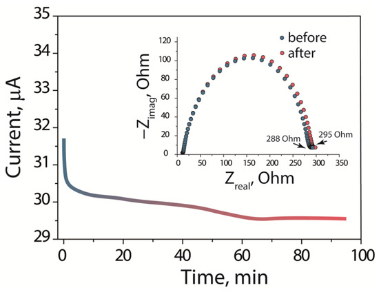
Figure 5.
The chronoamperometry curve at a potential of 0.01 V and impedance spectra before and after polarization with DC of the Li|SSEBS-Ph-EC-DMA|Li cell.
According to linear sweep voltammetry (Figure 6a), there are no anodic peaks for the electrolyte. A sharp increase in the current density corresponding to the electrolyte reduction is detected at only above 4.1 V vs. Li/Li+. According to cyclic voltammetry in the potential range of 2.5−4.1 V (when corresponding to the operating range of batteries with a LFP cathode), when there is an increasing cycle number then there follows a gradual decrease in the current in regard to the high-potential region (Figure 6b), which indicates an increase in the stability of the electrolyte during cycling.
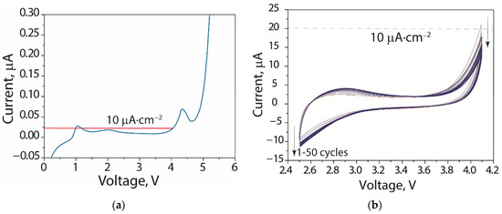
Figure 6.
(a) Linear voltammetry of SS|Li cells with SSEBS-Ph-EC-DMA-based electrolytes in the potential range 0–5.5 V and (b) cyclic voltammetry in the potential range 2.5−4.1 V for 50 cycles.
According to the data of the galvanostatic cycling of a symmetrical Li|Li cell, at a current density of 0.1 mA∙cm−2 with a cut-off capacity of 0.05 mAh∙cm−2, the electrolyte is stable during >700 h with an increase in overpotential from ±100 mV to ±230 mV after the first 100 cycles (Figure 7a). The values of overpotential are slightly higher than that, as reported for the single-ion conducting gel-polymer electrolyte with the comparable ionic conductivity [40,41], which may be due to the difference in polymer matrices and functional groups. Alternatively, it could be due to the difference in the mixture of solvents that plasticize the membrane. Having said that, it is worth noting the voltage profiles. In classical dual-ion conductors the concentration polarization is observed due to the parallel anion transport, which appears in the curves with an arc-like form (Figure 7b). The absence of polarization curves indicates the absence of the polarization effect for membrane-based electrolytes (Figure 7c) [42,43]. In addition, similar curve patterns have been reported in the works when examining single-ion conducting electrolytes [44,45].
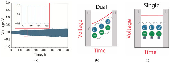
Figure 7.
(a) Galvanostatic cycling curves of a symmetrical Li|Li cell with SSEBS-Ph-EC-DMA-based electrolytes at 0.1 mA∙cm−2 with a cut-off capacity of 0.05 mAh∙cm−2. Schematic illustration of the behavior of (b) dual- and (c) single-ion conductors.
In order to evaluate the electrochemical characteristics of a lithium battery with a SSEBS-Ph-based electrolyte solvated by EC-DMA, LFP|Li cells were tested at different charge–discharge rates (Figure 8a). The charge–discharge curves of the LFP|Li cells show typical LiFePO4 plateaus corresponding to the Fe2+↔Fe3+ transition. At the same time, the difference between the average potentials of charge and discharge plateaus for the cell with the membrane electrolyte, as well as with the liquid electrolyte are, at the same charge/discharge rates, comparable (Table 1). This indicates that the membrane electrolyte does not contribute significantly to the battery resistance and that this parameter is determined by ohmic losses during the lithium transfer through the carbon coating, as well as through the charged (or discharged) layer of cathode material formed on the sample surface [46].
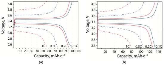
Figure 8.
Charge and discharge curves at various current densities of LFP|Li batteries with (a) SSEBS-Ph-EC-DMA and (b) liquid electrolytes.

Table 1.
Differences between charge and discharge potentials of LFP|Li batteries with SEBS-Ph-EC-DMA and liquid electrolytes at different C-rates.
The initial discharge capacity of the LFP|SSEBS-Ph-EC-DMA|Li cell was 100 mAh∙g−1 at 0.1C, which is ~28% lower than the capacity of the cell with standard liquid electrolytes based on 1M LiClO4 in an EC-DMC mixture (Figure 9). This can be explained by insufficient contact between the electrolyte film and the LFP cathode, which has low ionic conductivity. For example, in the case of the quasi-solid electrolyte, which is based on poly(vinylidene fluoride-co-hexafluoropropylene) with the conductivity value of 0.4 mS∙cm−1, the authors observed higher capacity values for the LFP|electrolyte|Li cell (143 mAh∙g−1) [47]. This is most likely associated with better electrode–electrolyte contact, which is realized due to the presence of LiTFSI, ethylene carbonate, and dimethyl carbonate mixture in the electrolyte, which impregnates the cathode material layer. In our case, lithium cations are produced by the functional groups of the membrane. We assume that the use of a lithium-conducting binder will make it possible to ensure a more complete extraction of lithium cations from a layer of cathode material and will endeavor, in future studies, to solve this problem. As the cycling rate increases, the SSEBS-Ph-EC-DMA electrolyte cell discharge capacity drops to 91, 74, and 50 mAh∙g−1 for the C-rates of 0.2C, 0.5C, and 1C, respectively. The rates of cell capacity drop with the membrane and liquid electrolytes are almost the same, e.g., when the charge/discharge rate is increased 10-fold (to 1C), the cell capacity decreases by ~50%. However, when returned to a rate of 0.1C, the capacity was restored and even increased slightly with an increasing number of cycles (Figure 9a). It is known that at high rates the charge–discharge processes are regulated by diffusion of ions through the electrolyte and the electrode/electrolyte interface [48], as well as when the film forms on the surface of the cathode material. The recovery of the initial cell capacity indicated that there was no degradation of the cell materials when the cycling rate was increased; in addition, the capacity drop at higher rates was due to kinetic limitations. It is also worth noting that the Coulomb efficiency of the cell with a membrane was ~100% for all C-rates, compared to the 95.4% for the cell with the liquid electrolyte. This indicates the high stability of the obtained membrane-based electrolyte.
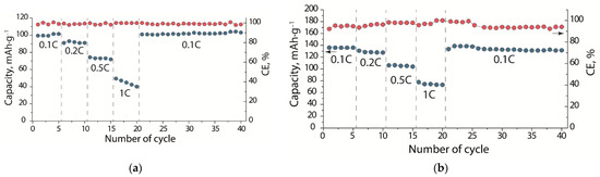
Figure 9.
Coulombic efficiency (red dots) and discharge capacity (blue dots) of LFP|Li cell with (a) SSEBS-Ph-EC-DMA and (b) 1M LiClO4 in an EC-DMC mixture electrolyte at different C-rates.
4. Conclusions
Gel-polymer electrolytes for lithium metal batteries based on block co-polymer poly(ethylene-ran-butylene)-block-polystyrene, which contained benzenesulfonylimide groups and were solvated by a mixture of ethylene carbonate—dimethylacetamide were obtained (solvent uptake was ~12 solvent molecules per one functional group of the membrane). The SSEBS-Ph-EC-DMA electrolyte exhibited an ionic conductivity of 0.6 mSm∙cm−1 at room temperature and had a lithium-ion transference number of 0.72. SSEBS-Ph-EC-DMA is characterized by a wide electrochemical stability window up to 4.1 V. Symmetric Li|Li cells with a membrane electrolyte that showed overpotential equal to ~0.10 V at the first cycles and <0.23 V after 700 h at ±0.1 mA∙cm−2. LFP|Li batteries with a membrane electrolyte showed discharge capacity values of 100, 91, 74, and 50 mAh∙g−1 at 0.1C, 0.2C, 0.5C, and 1C, respectively (Coulomb efficiency was ~100%).
Author Contributions
Conceptualization, D.V. and A.Y.; methodology, D.V.; software, D.V.; validation, A.Y. and S.N.; formal analysis, D.V.; investigation, D.V. and S.N.; resources, A.Y.; data curation, D.V.; writing—original draft preparation, D.V., S.N., and N.T.; writing—review and editing, A.Y.; visualization, D.V.; supervision, A.Y.; project administration, A.Y.; funding acquisition, A.Y. All authors have read and agreed to the published version of the manuscript.
Funding
This work was financially supported by the Ministry of Science and Higher Education of the Russian Federation as part of the State Assignment of the Kurnakov Institute of General and Inorganic Chemistry of the Russian Academy of Sciences.
Data Availability Statement
Data may be available on request.
Acknowledgments
The CHNS elemental analysis were performed using shared experimental facilities supported by the IGIC RAS state assignment.
Conflicts of Interest
The authors declare no conflict of interest.
References
- Tian, J.; Yu, L.; Xue, R.; Zhuang, S.; Shan, Y. Global Low-Carbon Energy Transition in the Post-COVID-19 Era. Appl. Energy 2021, 307, 118205. [Google Scholar] [CrossRef] [PubMed]
- Alent’ev, A.Y.; Volkov, A.V.; Vorotyntsev, I.V.; Maksimov, A.L.; Yaroslavtsev, A.B. Membrane Technologies for Decarbonization. Membr. Membr. Technol. 2021, 3, 255–273. [Google Scholar] [CrossRef]
- Koohi-Fayegh, S.; Rosen, M.A. A Review of Energy Storage Types, Applications and Recent Developments. J. Energy Storage 2020, 27, 101047. [Google Scholar] [CrossRef]
- Filippov, S.P.; Yaroslavtsev, A.B. Hydrogen Energy: Development Prospects and Materials. Russ. Chem. Rev. 2021, 90, 627–643. [Google Scholar] [CrossRef]
- Patrike, A.; Yadav, P.; Shelke, V.; Shelke, M. Research Progress and Perspective on Lithium/Sodium Metal Anode for Next-Generation Rechargeable Batteries: A Review. ChemSusChem 2022, 15, e202200504. [Google Scholar] [CrossRef] [PubMed]
- Guo, X.; Li, W.; Geng, P.; Zhang, Q.; Pang, H.; Xu, Q. Construction of SiO /Nitrogen-Doped Carbon Superstructures Derived from Rice Husks for Boosted Lithium Storage. J. Colloid Interface Sci. 2022, 606, 784–792. [Google Scholar] [CrossRef]
- Yoon, N.; Young, C.; Kang, D.; Park, H.; Lee, J.K. High-Conversion Reduction Synthesis of Porous Silicon for Advanced Lithium Battery Anodes. Electrochim. Acta 2021, 391, 138967. [Google Scholar] [CrossRef]
- Rao, X.; Lou, Y.; Zhong, S.; Wang, L.; Li, B.; Xiao, Y.; Peng, W.; Zhong, X.; Huang, J. Strategies for Dendrite-Free Lithium Metal Anodes: A Mini-Review. J. Electroanal. Chem. 2021, 897, 115499. [Google Scholar] [CrossRef]
- Yamaki, J.; Tobishima, S.; Hayashi, K.; Saito, K.; Nemoto, Y.; Arakawa, M. A Consideration of the Morphology of Electrochemically Deposited Lithium in an Organic Electrolyte. J. Power Sources 1998, 74, 219–227. [Google Scholar] [CrossRef]
- Chen, X.; Zhao, B.; Yan, C.; Zhang, Q. Review on Li Deposition in Working Batteries: From Nucleation to Early Growth. Adv. Mater. 2021, 33, 2004128. [Google Scholar] [CrossRef]
- Chazalviel, J.-N. Electrochemical Aspects of the Generation of Ramified Metallic Electrodeposits. Phys. Rev. A 1990, 42, 7355–7367. [Google Scholar] [CrossRef] [PubMed]
- Brissot, C.; Rosso, M.; Chazalviel, J.-N.; Baudry, P.; Lascaud, S. In Situ Study of Dendritic Growth Inlithium/PEO-Salt/Lithium Cells. Electrochim. Acta 1998, 43, 1569–1574. [Google Scholar] [CrossRef]
- Qian, J.; Henderson, W.A.; Xu, W.; Bhattacharya, P.; Engelhard, M.; Borodin, O.; Zhang, J.-G. High Rate and Stable Cycling of Lithium Metal Anode. Nat. Commun. 2015, 6, 6362. [Google Scholar] [CrossRef] [PubMed]
- Voropaeva, D.Y.; Safronova, E.Y.; Novikova, S.A.; Yaroslavtsev, A.B. Recent Progress in Lithium-Ion and Lithium Metal Batteries. Mendeleev Commun. 2022, 32, 287–297. [Google Scholar] [CrossRef]
- Alvarez-Tirado, M.; Guzmán-González, G.; Vauthier, S.; Cotte, S.; Guéguen, A.; Castro, L.; Mecerreyes, D. Designing Boron-Based Single-Ion Gel Polymer Electrolytes for Lithium Batteries by Photopolymerization. Macromol. Chem. Phys. 2022, 223, 2100407. [Google Scholar] [CrossRef]
- Voropaeva, D.; Golubenko, D.; Merkel, A.; Yaroslavtsev, A. Membranes with Novel Highly-Delocalized Sulfonylimide Anions for Lithium-Ion Batteries. J. Memb. Sci. 2020, 601, 117918. [Google Scholar] [CrossRef]
- Liu, J.; Pickett, P.D.; Park, B.; Upadhyay, S.P.; Orski, S.V.; Schaefer, J.L. Non-Solvating, Side-Chain Polymer Electrolytes as Lithium Single-Ion Conductors: Synthesis and Ion Transport Characterization. Polym. Chem. 2020, 11, 461–471. [Google Scholar] [CrossRef]
- Ahmed, F.; Choi, I.; Rahman, M.M.; Jang, H.; Ryu, T.; Yoon, S.; Jin, L.; Jin, Y.; Kim, W. Remarkable Conductivity of a Self-Healing Single-Ion Conducting Polymer Electrolyte, Poly(Ethylene-Co-Acrylic Lithium (Fluoro Sulfonyl)Imide), for All-Solid-State Li-Ion Batteries. ACS Appl. Mater. Interfaces 2019, 11, 34930–34938. [Google Scholar] [CrossRef]
- Zhu, J.; Zhang, Z.; Zhao, S.; Westover, A.S.; Belharouak, I.; Cao, P. Single-Ion Conducting Polymer Electrolytes for Solid-State Lithium-Metal Batteries: Design, Performance, and Challenges. Adv. Energy Mater. 2021, 11, 2003836. [Google Scholar] [CrossRef]
- Rohan, R.; Sun, Y.; Cai, W.; Zhang, Y.; Pareek, K.; Xu, G.; Cheng, H. Functionalized Polystyrene Based Single Ion Conducting Gel Polymer Electrolyte for Lithium Batteries. Solid State Ion. 2014, 268, 294–299. [Google Scholar] [CrossRef]
- Feng, S.; Shi, D.; Liu, F.; Zheng, L.; Nie, J.; Feng, W.; Huang, X.; Armand, M.; Zhou, Z. Single Lithium-Ion Conducting Polymer Electrolytes Based on Poly[(4-Styrenesulfonyl)(Trifluoromethanesulfonyl)Imide] Anions. Electrochim. Acta 2013, 93, 254–263. [Google Scholar] [CrossRef]
- Feiring, A.E.; Choi, S.K.; Doyle, M.; Wonchoba, E.R. Novel Aromatic Polymers with Pendant Lithium Perfluoroalkylsulfonate or Sulfonimide Groups. Macromolecules 2000, 33, 9262. [Google Scholar] [CrossRef]
- Ma, Q.; Zhang, H.; Zhou, C.; Zheng, L.; Cheng, P.; Nie, J.; Feng, W.; Hu, Y.S.; Li, H.; Huang, X.; et al. Single Lithium-Ion Conducting Polymer Electrolytes Based on a Super-Delocalized Polyanion. Angew Chem. Int. Ed. Engl. 2016, 55, 2521–2525. [Google Scholar] [CrossRef] [PubMed]
- Li, Z.; Yao, Q.; Zhang, Q.; Zhao, Y.; Gao, D.; Li, S.; Xu, S. Creating Ionic Channels in Single-Ion Conducting Solid Polymer Electrolyte by Manipulating Phase Separation Structure. J. Mater. Chem. A 2018, 6, 24848–24859. [Google Scholar] [CrossRef]
- Voropaeva, D.Y.; Novikova, S.A.; Yaroslavtsev, A.B. Polymer Electrolytes for Metal-Ion Batteries. Russ. Chem. Rev. 2020, 89, 1132–1155. [Google Scholar] [CrossRef]
- Faridi, M.; Naji, L.; Kazemifard, S.; Pourali, N. Electrochemical Investigation of Gel Polymer Electrolytes Based on Poly(Methyl Methacrylate) and Dimethylacetamide for Application in Li-Ion Batteries. Chem. Pap. 2018, 72, 2289–2300. [Google Scholar] [CrossRef]
- Xu, M.; Hao, L.; Liu, Y.; Li, W.; Xing, L.; Li, B. Experimental and Theoretical Investigations of Dimethylacetamide (DMAc) as Electrolyte Stabilizing Additive for Lithium Ion Batteries. J. Phys. Chem. C 2011, 115, 6085–6094. [Google Scholar] [CrossRef]
- Bae, S.-Y.; Shin, W.-K.; Kim, D.-W. Protective Organic Additives for High Voltage LiNi0.5Mn1.5O4 Cathode Materials. Electrochim. Acta 2014, 125, 497–502. [Google Scholar] [CrossRef]
- Walker, W.; Giordani, V.; Uddin, J.; Bryantsev, V.S.; Chase, G.V.; Addison, D. A Rechargeable Li–O2 Battery Using a Lithium Nitrate/N,N-Dimethylacetamide Electrolyte. J. Am. Chem. Soc. 2013, 135, 2076–2079. [Google Scholar] [CrossRef]
- Vedenyapina, M.D.; Kulova, T.L.; Kudryashova, Y.O.; Skundin, A.M.; Malyshev, O.R.; Glukhov, L.M. Interaction between Sodium and Dimethylacetamide as the Cause of Instability in the Operation of a Sodium-Ion Battery. Russ. J. Phys. Chem. A 2020, 94, 1276–1279. [Google Scholar] [CrossRef]
- Kulova, T.; Skundin, A.; Chekannikov, A.; Novikova, S.; Voropaeva, D.; Yaroslavtsev, A. Sodium Rechargeable Batteries with Electrolytes Based on Nafion Membranes Intercalated by Mixtures of Organic Solvents. Batteries 2018, 4, 61. [Google Scholar] [CrossRef]
- Stolz, L.; Pfeiffer, F.; Baghernejad, M.; Winter, M.; Kasnatscheew, J. Remark on Conductivity Measurements: The Special Case of Single-Ion Conducting Electrolytes on Blocking Electrodes. ACS Appl. Energy Mater. 2022. Available online: https://pubs.acs.org/doi/10.1021/acsaem.2c01034 (accessed on 18 November 2022). [CrossRef]
- Evans, J.; Vincent, C.A.; Bruce, P.G. Electrochemical Measurement of Transference Numbers in Polymer Electrolytes. Polymer 1987, 28, 2324–2328. [Google Scholar] [CrossRef]
- Kapaev, R.R.; Novikova, S.A.; Chekannikov, A.A.; Gryzlov, D.Y.; Kulova, T.L.; Skundin, A.M.; Yaroslavtsev, A.B. Effect of Carbon Sources and Synthesis Conditions on the LiFePo4/C Cathode Properties. Rev. Adv. Mater. Sci. 2018, 57, 183–192. [Google Scholar] [CrossRef]
- Socrates, G. Infrared and Raman Characteristic Group Frequencies. Tables and Charts, 3rd ed.; John Wiley & Son, Ltd.: Baffins Lane, UK, 2001. [Google Scholar]
- Hwang, H.Y.; Koh, H.C.; Rhim, J.W.; Nam, S.Y. Preparation of Sulfonated SEBS Block Copolymer Membranes and Their Permeation Properties. Desalination 2008, 233, 173–182. [Google Scholar] [CrossRef]
- Stenina, I.A.; Yaroslavtsev, A.B. Ionic Mobility in Ion-Exchange Membranes. Membranes 2021, 11, 198. [Google Scholar] [CrossRef]
- Diederichsen, K.M.; McShane, E.J.; McCloskey, B.D. Promising Routes to a High Li + Transference Number Electrolyte for Lithium Ion Batteries. ACS Energy Lett. 2017, 2, 2563–2575. [Google Scholar] [CrossRef]
- Zhang, H.; Li, C.; Piszcz, M.; Coya, E.; Rojo, T.; Rodriguez-Martinez, L.M.; Armand, M.; Zhou, Z. Single Lithium-Ion Conducting Solid Polymer Electrolytes: Advances and Perspectives. Chem. Soc. Rev. 2017, 46, 797–815. [Google Scholar] [CrossRef] [PubMed]
- Liu, K.; Jiang, S.; Dzwiniel, T.; Kim, H.-K.; Yu, Z.; Dietz Rago, N.L.; Kim, J.J.; Fister, T.T.; Yang, J.; Liu, Q.; et al. Molecular Design of a Highly Stable Single-Ion Conducting Polymer Gel Electrolyte. ACS Appl. Mater. Interfaces 2020, 12, 29162–29172. [Google Scholar] [CrossRef] [PubMed]
- Li, C.; Chen, Y.; Zhang, Y.; Bao, H. A gel porous single-ion conducting polyelectrolyte with double anionic functional group for enhancing lithium ion battery performance. Mater. Lett. 2021, 288, 129309. [Google Scholar] [CrossRef]
- Bai, P.; Li, J.; Brushett, F.R.; Bazant, M.Z. Transition of Lithium Growth Mechanisms in Liquid Electrolytes. Energy Environ. Sci. 2016, 9, 3221–3229. [Google Scholar] [CrossRef]
- Borzutzki, K.; Dong, K.; Nair, J.R.; Wolff, B.; Hausen, F.; Eichel, R.-A.; Winter, M.; Manke, I.; Brunklaus, G. Lithium Deposition in Single-Ion Conducting Polymer Electrolytes. Cell Rep. Phys. Sci. 2021, 2, 100496. [Google Scholar] [CrossRef]
- Chen, X.; Sun, C.; Wang, K.; Dong, W.; Han, J.; Ning, D.; Li, Y.; Wu, W.; Yang, C.; Lu, Z. An Ultra-Thin Crosslinked Carbonate Ester Electrolyte for 24 V Bipolar Lithium-Metal Batteries. J. Electrochem. Soc. 2022, 169, 090509. [Google Scholar] [CrossRef]
- Zhou, D.; Tkacheva, A.; Tang, X.; Sun, B.; Shanmukaraj, D.; Li, P.; Zhang, F.; Armand, M.; Wang, G. Stable Conversion Chemistry-Based Lithium Metal Batteries Enabled by Hierarchical Multifunctional Polymer Electrolytes with Near-Single Ion Conduction. Angew. Chem. 2019, 131, 6062–6067. [Google Scholar] [CrossRef]
- Safronov, D.V.; Novikova, S.A.; Skundin, A.M.; Yaroslavtsev, A.B. Lithium Intercalation and Deintercalation Processes in Li4Ti5O12 and LiFePO4. Inorg. Mater. 2012, 48, 57–61. [Google Scholar] [CrossRef]
- Zhai, L.; Zhang, W.; Gong, H.; Li, Y.; Gao, M.; Zhang, X.; Li, D.; Zhou, Y.; Dong, C.; Liu, W.; et al. Quasi-solid polymer electrolytes with fast interfacial transport for lithium metal batteries. Surf. Interfaces 2022, 34, 102299. [Google Scholar] [CrossRef]
- Evshchik, E.Y.; Sanginov, E.A.; Kayumov, R.R.; Zhuravlev, V.D.; Bushkova, O.V.; Dobrovolsky, Y.A. Li4Ti5O12/LiFePO4 Solid-State Lithium-Ion Full Cell with LithiatedNafion Membrane. Int. J. Electrochem. Sci. 2020, 15, 2216–2225. [Google Scholar] [CrossRef]


Publisher’s Note: MDPI stays neutral with regard to jurisdictional claims in published maps and institutional affiliations. |
© 2022 by the authors. Licensee MDPI, Basel, Switzerland. This article is an open access article distributed under the terms and conditions of the Creative Commons Attribution (CC BY) license (https://creativecommons.org/licenses/by/4.0/).