
Study on the Solid Production Mechanism of the Fractured Granite Reservoirs-Example of YL Area in Qiongdongnan Basin
 ,
,
Abstract
:1. Introduction
2. Characteristics of Granite Reservoirs in YL Area of Qiongdongnan Basin
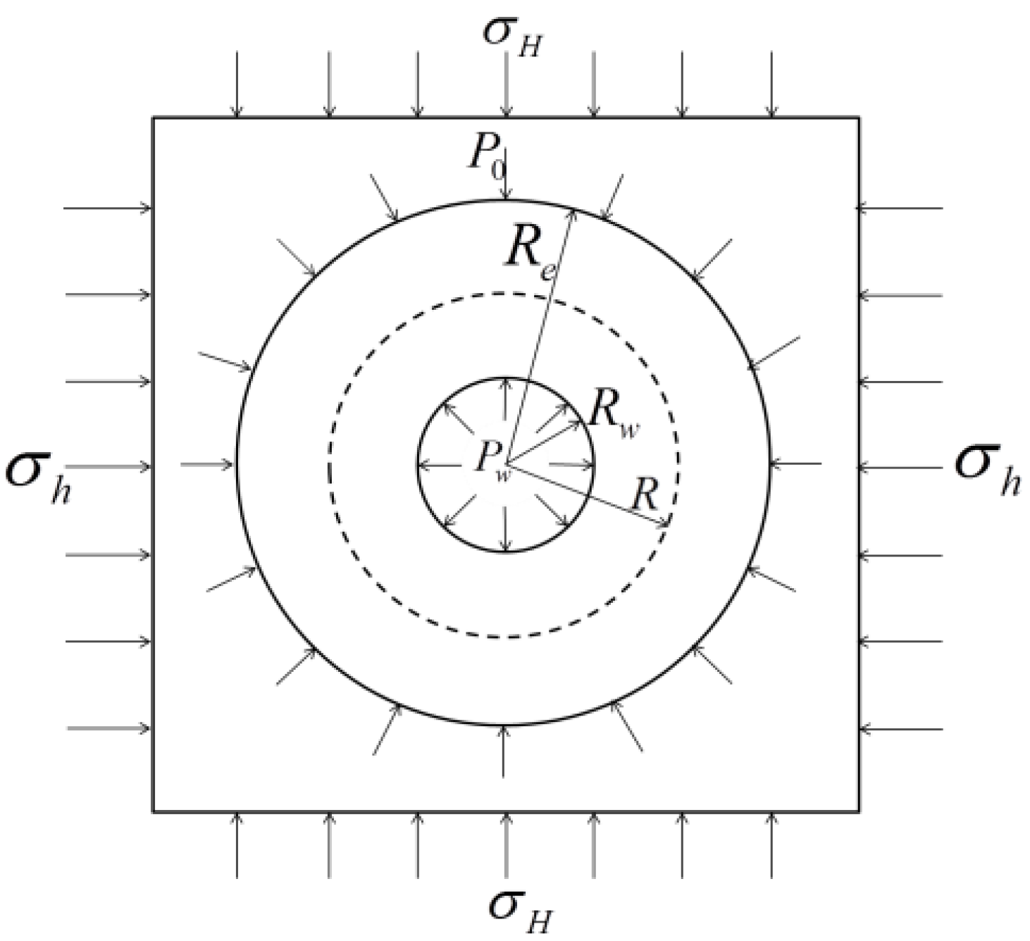
3. Solid Production Model and Evaluation Method for Fractured Granite Reservoirs
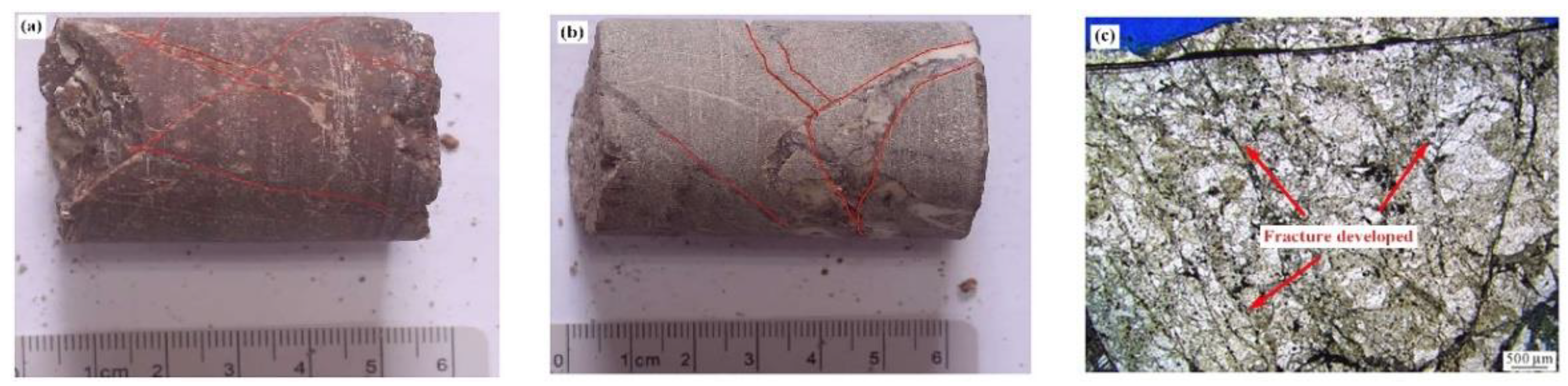
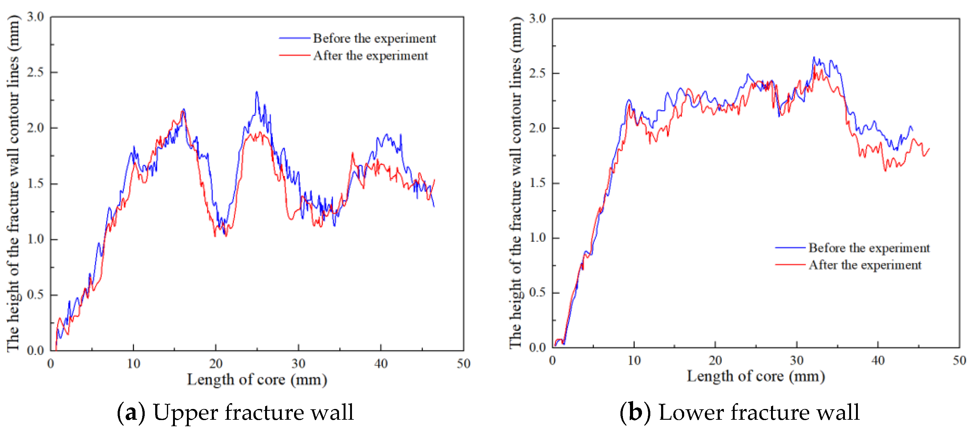
3.1. Shedding of Fracture Filling and Solid Particles on the Fracture Wall
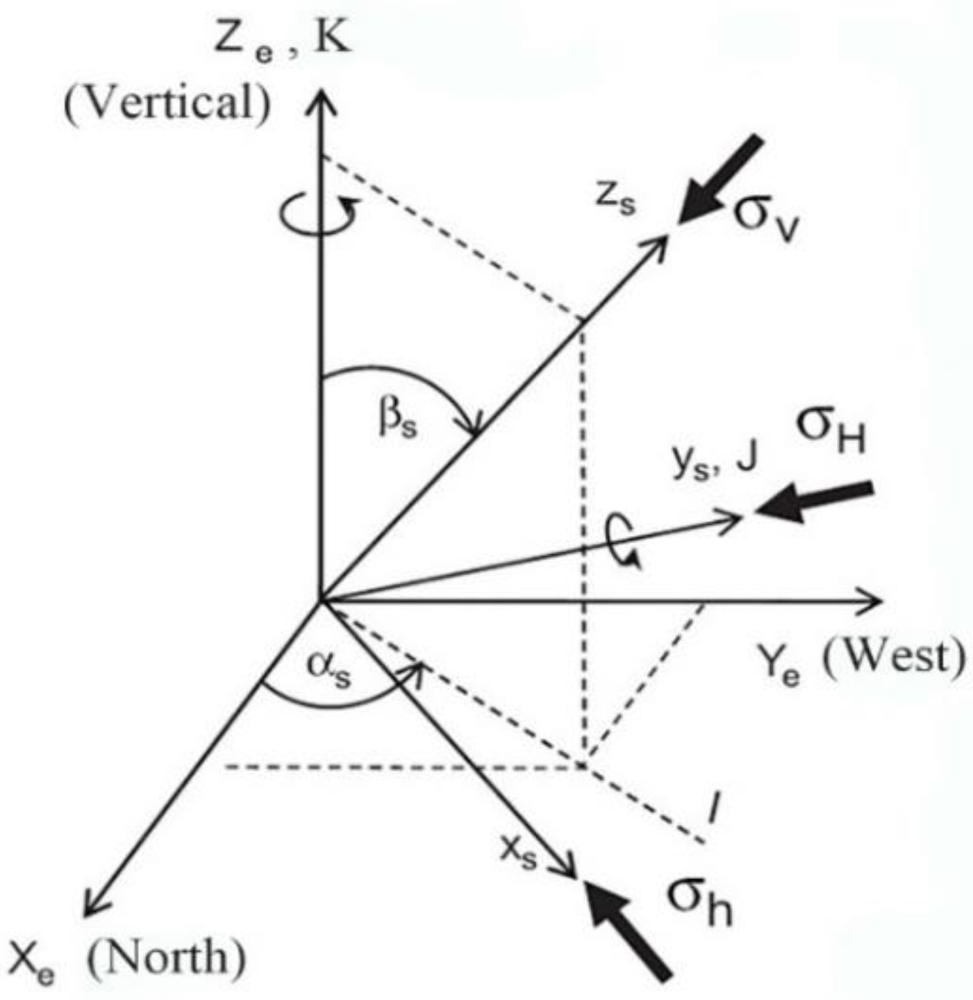
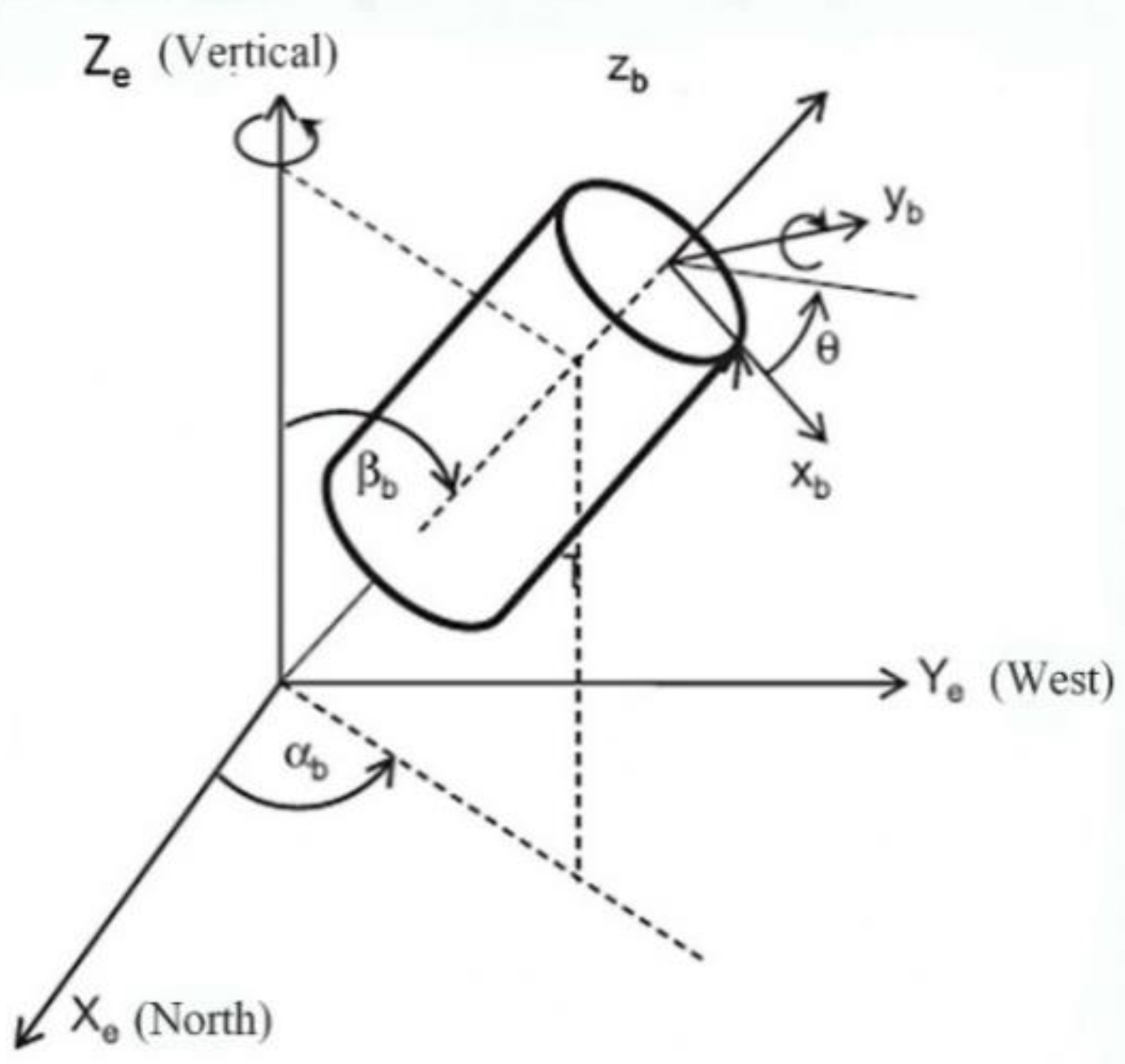
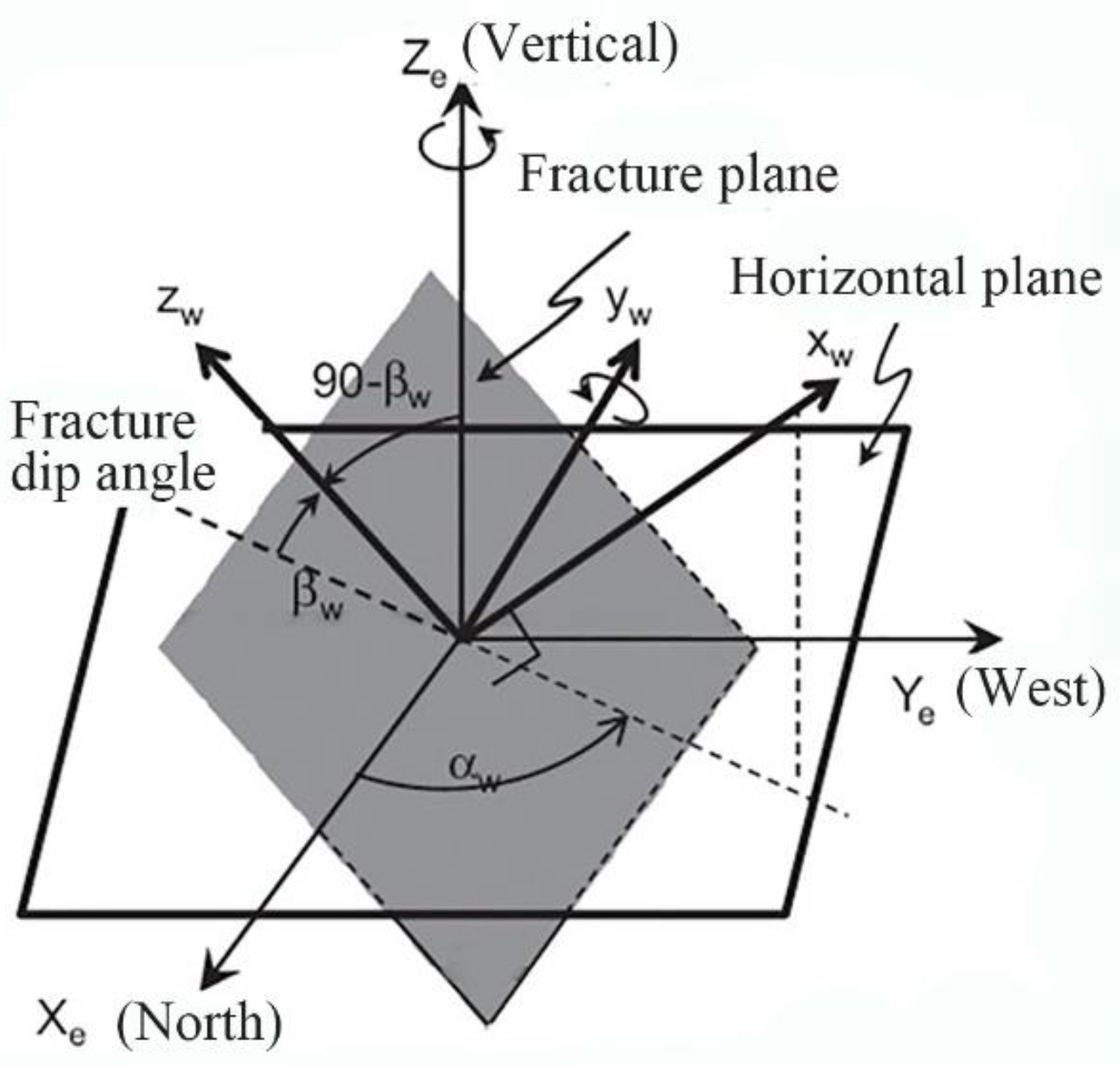
3.2. Shear Slip Failure along the Fracture
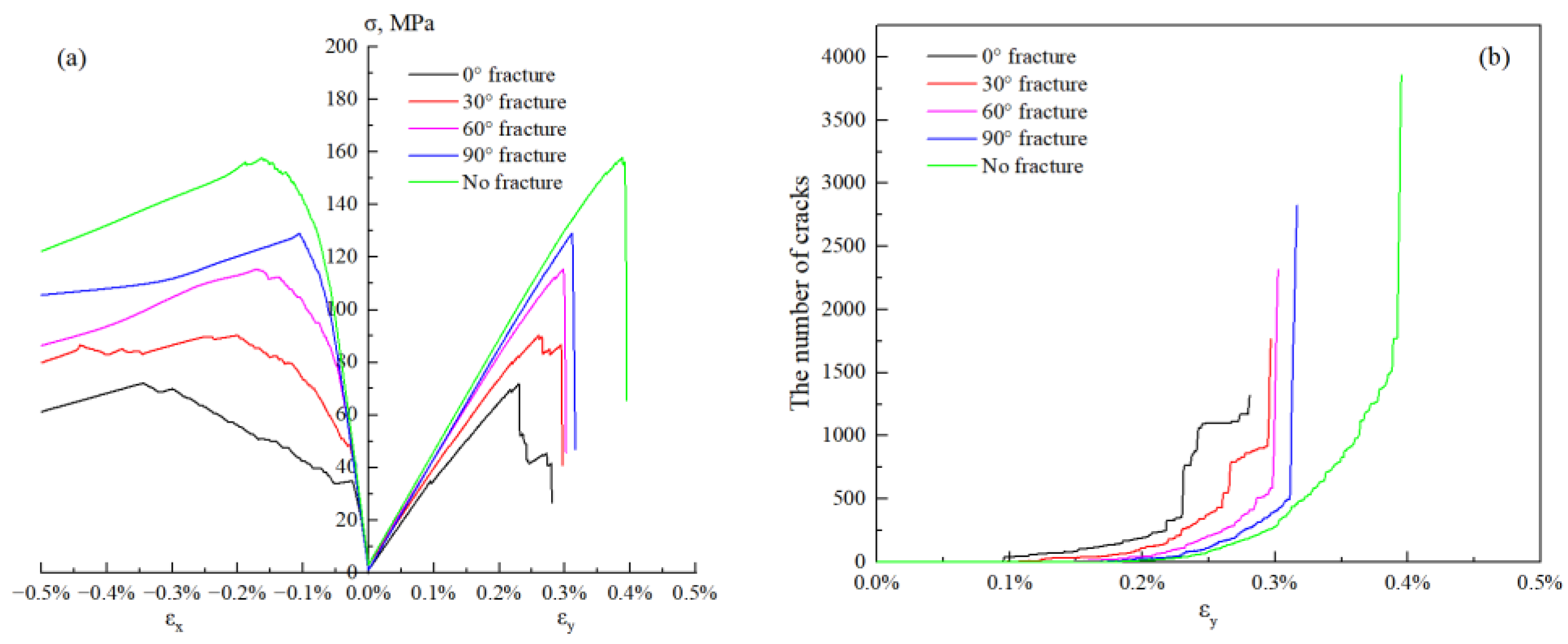
3.3. Shear Failure of Granite Matrix
4. Conclusions
Author Contributions
Funding
Institutional Review Board Statement
Informed Consent Statement
Data Availability Statement
Conflicts of Interest
References
- Koning, T. Oil and gas production from basement reservoirs: Examples from Indonesia, USA and Venezuela. Geol. Soc. Lond. Spec. Publ. 2003, 214, 83–92. [Google Scholar] [CrossRef]
- Micarelli, L.; Benedicto, A.; Wibberley, C.A.J. Structural evolution and permeability of normal fault zones in highly porous carbonate rocks. J. Struct. Geol. 2006, 28, 1214–1227. [Google Scholar] [CrossRef]
- Huang, J.H.; Tan, X.F.; Cheng, C.J.; Li, Z.M.; Ma, L.J.; Zhang, H.L.; Wu, Y.X. Structural features of weathering crust of granitic basement rock and its petroleum geological significance: A case study of Basement weathering crust of Dongping Area in Qaidam Basin. Earth Sci. 2016, 41, 2041–2060. [Google Scholar]
- Ye, T.; Wei, A.; Sun, Z.; Gao, K.; Cheng, Q. The reservoir characteristics and their significance for deliverability in metamorphic granite buried hill: A case study from the JZS oil field in the Liaodong Bay Basin, NE China. Arab. J. Geosci. 2019, 12, 1–9. [Google Scholar] [CrossRef]
- You, L.; Xu, S.; Mao, X.; Zhong, J.; Jiao, Y.; Xiong, X. Reservoir Characteristics and Genetic Mechanisms of the Mesozoic Granite Buried Hills in the Deep-water of the Qiongdongnan Basin, Northern South China Sea. Acta Geol. Sin.-Engl. Ed. 2021, 95, 259–267. [Google Scholar] [CrossRef]
- Ji, M.; Zeng, Q.; Yang, H.; Guo, S.; Zhong, K. Structural characteristics of central depression belt in deep-water area of the Qiongdongnan Basin and the hydrocarbon discovery of Songnan low bulge. Acta Oceanol. Sin. 2021, 40, 42–53. [Google Scholar] [CrossRef]
- Song, Y.; Ranjith, P.G.; Wu, B. Development and experimental validation of a computational fluid dynamics-discrete element method sand production model. J. Nat. Gas Sci. Eng. 2020, 73, 103052. [Google Scholar] [CrossRef]
- Li, X.; Yi, L.; Fan, Z. Sand Production of the Shale Gas Well in Different Production Periods: Structure and Component. Energies 2021, 14, 5588. [Google Scholar] [CrossRef]
- Morita, N.; Whitfill, D.L.; Massie, I.; Knudsen, T.W. Realistic sand-production prediction: Numerical approach. SPE Prod. Eng. 1989, 4, 15–24. [Google Scholar] [CrossRef]
- Vaziri, H.H. Theoretical analysis of stress, pressure, and formation damage during production. J. Can. Pet. Technol. 1988, 27, 880613. [Google Scholar] [CrossRef]
- Perkins, T.K.; Weingarten, J.S. Stability and failure of spherical cavities in unconsolidated sand and weakly consolidated rock. In Proceedings of the SPE Annual Technical Conference and Exhibition, Houston, TX, USA, 2–5 October 1988. SPE-18244. [Google Scholar]
- Vardoulakis, I.; Stavropoulou, M.; Papanastasiou, P. Hydro-mechanical aspects of the sand production problem. Transp. Porous Media 1996, 22, 225–244. [Google Scholar] [CrossRef]
- Wu, B.; Tan, C.P.; Lu, N. Effect of water cut on sand production—An experimental study. SPE Prod. Oper. 2006, 21, 349–356. [Google Scholar] [CrossRef]
- Eshiet, K.; Sheng, Y. Influence of rock failure behaviour on predictions in sand production problems. Environ. Earth Sci. 2013, 70, 1339–1365. [Google Scholar] [CrossRef]
- Li, X.; Feng, Y.; Gray, K.E. A hydro-mechanical sand erosion model for sand production simulation. J. Pet. Sci. Eng. 2018, 166, 208–224. [Google Scholar] [CrossRef]
- Veeken, C.A.M.; Davies, D.R.; Kenter, C.J.; Kooijman, A.P. Sand production prediction review: Developing an integrated approach. In Proceedings of the 1991 SPE Annual Technical Conference and Exhibition, Dallas, TX, USA, 6–9 October 1991. SPE 22792. [Google Scholar]
- Van den Hoek, P.J.; Hertogh, G.M.M.; Kooijman, A.P.; De Bree, P.; Kenter, C.J.; Papamichos, E. A new concept of sand production prediction: Theory and laboratory experiments. SPE Drill. Complet. 2000, 15, 261–273. [Google Scholar] [CrossRef]
- Rahmati, H.; Jafarpour, M.; Azadbakht, S.; Nouri, A.; Vaziri, H.; Chan, D.; Xiao, Y. Review of sand production prediction models. J. Pet. Eng. 2013, 2013, 864981. [Google Scholar] [CrossRef] [Green Version]
- Cui, Y.; Nouri, A.; Chan, D.; Rahmati, E. A new approach to DEM simulation of sand production. J. Pet. Sci. Eng. 2016, 147, 56–67. [Google Scholar] [CrossRef]
- Vriezen, P.B.; Spijker, A.; Van der Vlis, A.C. Erosion of perforation tunnels in gas wells. In Proceedings of the Fall Meeting of the Society of Petroleum Engineers of AIME, Dallas, TX, USA, 28 September–1 October 1975. SPE-5661. [Google Scholar]
- Antheunis, D.; Vriezen, P.B.; Schipper, B.A.; Van der Vlis, A.C. Perforation collapse: Failure of perforated friable sandstones. In Proceedings of the SPE European Spring Meeting, Amsterdam, The Netherlands, 8–9 April 1976. SPE-5750. [Google Scholar]
- Wang, X.; Yang, W.; Yang, H. The sanding mechanism and sanding critical drawdown calculation in loose sandstone. Nat. Gas Ind. 2009, 29, 72–75. [Google Scholar]
- Zhong, B.; Ma, L.; Yang, Y.; Xia, C.; Li, J. Study on Sand Producing Mechanism of Gas Wells and Counter-Measures for Gas Reservoirs with Multilayer Sand. Nat. Gas Ind. 2004, 24, 89–92. [Google Scholar]
- Wang, Z.; Peden, J.M.; Damasena, E.S.H. The prediction of operating conditions to constrain sand production from a gas well. In Proceedings of the SPE Production Operations Symposium, Oklahoma City, OK, USA, 7–9 April 1991. SPE-21681. [Google Scholar]
- Ong, S.; Ramos, R.; Zheng, Z. Sand production prediction in high rate, perforated and open-hole gas wells. In Proceedings of the SPE International Symposium on Formation Damage Control, Lafayette, LA, USA, 23–24 February 2000. SPE-58721. [Google Scholar]
- Morita, N.; Whitfill, D.L.; Fedde, O.P.; Lovik, T.H. Parametric study of sand-production prediction: Analytical approach. SPE Prod. Eng. 1989, 4, 25–33. [Google Scholar] [CrossRef]
- Bruno, M.S.; Bovberg, C.A.; Meyer, R.F. Some influences of saturation and fluid flow on sand production: Laboratory and discrete element model investigations. In Proceedings of the SPE Annual Technical Conference and Exhibition, Denver, CO, USA, 6–9 October 1996. SPE-36534. [Google Scholar]
- Hou, M.; Cao, H.; Li, H.; Chen, A.; Wei, A.; Chen, Y.; Wang, Y.; Zhou, X.; Ye, T. Characteristics and controlling factors of deep buried-hill reservoirs in the BZ19-6 structural belt, Bohai Sea area. Nat. Gas Ind. B 2019, 6, 305–316. [Google Scholar] [CrossRef]
- Ye, T.; Niu, C.; Wei, A. Characteristics and genetic mechanism of large granitic buried-hill reservoir, a case study from PengLai oil field of Bohai Bay Basin, north China. J. Pet. Sci. Eng. 2020, 189, 106988. [Google Scholar] [CrossRef]
- Dou, L.; Xiao, Y.; Gao, H.; Wang, R.; Liu, C.; Sun, H. The study of enhanced displacement efficiency in tight sandstone from the combination of spontaneous and dynamic imbibition. J. Pet. Sci. Eng. 2021, 199, 108327. [Google Scholar] [CrossRef]
- Lee, H.; Jeon, S. An experimental and numerical study of fracture coalescence in pre-cracked specimens under uniaxial compression. Int. J. Solids Struct. 2011, 48, 979–999. [Google Scholar] [CrossRef] [Green Version]
- Jiang, J.; Li, X. Sand Production Mechanism Analysis of Deep Tight Sandstone Gas Reservoir in Keshen Block. IOP Conf. Ser. Earth Environ. Sci. 2021, 781, 022022. [Google Scholar] [CrossRef]
- Yang, X.; Jin, X.; Zhang, Y.; Yin, Q.; McLennan, J.; Dai, C.; Fan, W.; Xiao, Y. Investigating the fundamental mechanisms governing solid production in superdeep hot tight gas reservoirs and exploring potential solutions. In Proceedings of the SPE Annual Technical Conference and Exhibition, Dubai, United Arab Emirates, 26–28 September 2016. SPE-181731. [Google Scholar]
- Zhang, D.; Kang, Y.; You, L.; Zhou, Z.; Zhu, J.; Li, J. Mechanisms of sand production from fracture wall and its effect on stress sensitivity in ultra-deep tight sandstone reservoirs. Pet. Geol. Recovery Effic. 2017, 24, 72–78. [Google Scholar]
- Sun, H.; Chang, B.; Zhang, J.; Zhang, J.; Wang, X.; Chen, B.; Liu, L. Causes of sand production and its influence on the output of fractured tight sandstone gas reservoirs: A case study on the Keshen Gas Field, Tarim Basin. Nat. Gas Ind. 2018, 38, 52–58. [Google Scholar]
- Xu, S.L.; You, L.; Mao, X.L.; Zhong, J.; Wu, S.J. Reservoir characteristics and controlling factors of granite buried hill in Songnan Low Uplift, Qiongdongnan Basin. Earth Sci. 2019, 44, 2717–2728. [Google Scholar]
- Li, H.; Wang, P.; Xu, S.; Liu, Y.; Wu, S.; Jiao, Y.; Xiong, X. Reservoir characteristics and controlling factors of Prepaleogene granite buried-hill in Songnan low uplift, Qiongdongnan Basin. World Geol. 2022, 41, 1–15. [Google Scholar]
- Ismail, N.I.; Naz, M.Y.; Shukrullah, S.; Sulaiman, S.A. Mechanical earth modeling and sand onset production prediction for Well X in Malay Basin. J. Pet. Explor. Prod. Technol. 2020, 10, 2753–2758. [Google Scholar] [CrossRef]
- Sanchez, E.C.M.; Cordero, J.A.R.; Roehl, D. Numerical simulation of three-dimensional fracture interaction. Comput. Geotech. 2020, 122, 103528. [Google Scholar] [CrossRef]
- Wang, H.; Sharma, M.M. The role of elasto-plasticity in cavity shape and sand production in oil and gas wells. SPE J. 2019, 24, 744–756. [Google Scholar] [CrossRef]
- Farsimadan, M.; Dehghan, A.N.; Khodaei, M. Determining the domain of in situ stress around Marun Oil Field’s failed wells, SW Iran. J. Pet. Explor. Prod. Technol. 2020, 10, 1317–1326. [Google Scholar] [CrossRef] [Green Version]
- Fjaer, E.; Holt, R.M.; Horsrud, P.; Raaen, A.M. Petroleum Related Rock Mechanics, 2nd ed.; Elsevier: Amsterdam, The Netherlands, 2008; pp. 341–369. [Google Scholar]
- Shabdirova, A.; Minh, N.H.; Zhao, Y. A sand production prediction model for weak sandstone reservoir in Kazakhstan. J. Rock Mech. Geotech. Eng. 2019, 11, 760–769. [Google Scholar] [CrossRef]


| The Angle of Pefabricated Fracture | No Prefabricated Fracture | 0° | 30° | 60° | 90° |
|---|---|---|---|---|---|
| Experimental model | 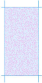 | 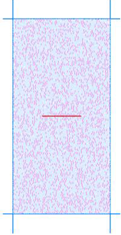 |  |  | 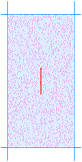 |
| Failure characteristic |  |  | 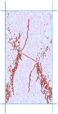 | 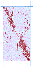 |  |
| The Angle of Pefabricated Fracture | No Prefabricated Fracture | 0° | 30° | 60° | 90° |
|---|---|---|---|---|---|
| Experimental model |  | 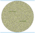 |  |  | 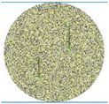 |
| Failure characteristic |  | 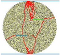 | 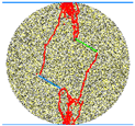 | 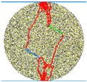 |  |
Publisher’s Note: MDPI stays neutral with regard to jurisdictional claims in published maps and institutional affiliations. |
© 2022 by the authors. Licensee MDPI, Basel, Switzerland. This article is an open access article distributed under the terms and conditions of the Creative Commons Attribution (CC BY) license (https://creativecommons.org/licenses/by/4.0/).
Share and Cite
Zuo, X.; Wang, T.; Shi, L.; Lei, L.; Wu, J.; Dou, L.; Li, T. Study on the Solid Production Mechanism of the Fractured Granite Reservoirs-Example of YL Area in Qiongdongnan Basin. Processes 2022, 10, 2556. https://doi.org/10.3390/pr10122556
Zuo X, Wang T, Shi L, Lei L, Wu J, Dou L, Li T. Study on the Solid Production Mechanism of the Fractured Granite Reservoirs-Example of YL Area in Qiongdongnan Basin. Processes. 2022; 10(12):2556. https://doi.org/10.3390/pr10122556
Chicago/Turabian StyleZuo, Xiongdi, Tao Wang, Lanling Shi, Lei Lei, Jian Wu, Liangbin Dou, and Tiantai Li. 2022. "Study on the Solid Production Mechanism of the Fractured Granite Reservoirs-Example of YL Area in Qiongdongnan Basin" Processes 10, no. 12: 2556. https://doi.org/10.3390/pr10122556