Article

Effect of Annular Gas–Liquid Two-Phase Flow on Lateral Vibration of Drill String in Horizontal Drilling for Natural Gas Hydrate

1
Department of Mechanical Science and Engineering, Northeast Petroleum University, Daqing 163318, China
2
Offshore Drilling Company, SINOPEC Shengli Petroleum Engineering Co., Ltd., Dongying 257000, China
*
Authors to whom correspondence should be addressed.
Processes 2023, 11(1), 54; https://doi.org/10.3390/pr11010054
Submission received: 1 December 2022 / Revised: 14 December 2022 / Accepted: 22 December 2022 / Published: 26 December 2022

Abstract

:
NGH (natural gas hydrate) is a sort of green energy with huge reserves. When drilling and exploiting NGH, the complex drilling environment will aggravate the vibration of the drill string, which will destroy the stability of the NGH reservoir and make it decompose to produce a large amount of gas. Gas flows into the annular with the drilling fluid, filling the annular with a gas–liquid two-phase flow with a complex variation in the characteristic parameters of the pipe flow. The mixed gas–liquid annular flow will make the drill string vibration more complex and intense. In this study, the nonlinear mathematical model of the drill string lateral vibration is established by considering the influence of the internal and external fluids, gravity, and the bottom axial force on the lateral vibration of the drill string. The effect of the annular fluid velocity and gas content on the lateral vibration of the drill string was studied through experiments and numerical simulations. This study found that, with an increase in annular fluid velocity and gas content, the stability of the drill string is weakened, and the lateral vibration is intensified, so the effect of the annular fluid velocity on the lateral vibration of drill string is greater than that of the annular gas content.

1. Introduction

Natural gas hydrate (also known as combustible ice) is a new kind of green energy. NGH is a kind of clathrate crystalline solid. This solid contains a large number of water cavities, which contain a large number of gas molecules (mainly methane). After the decomposition of 1 m3 NGH, natural gas in a 164 m3 standard condition can be released. NGH is considered as an alternative energy for the future due to its huge reserves and its clean and pollution-free characteristics. At present, the discovered NGH reserves in the world are about 2.1 × 10¹⁶ m3. These are about twice the world’s proven oil and gas reserves [1,2,3,4,5]. With the burning of a large amount of fossil energy, a lot of greenhouse gases (mainly CO2) are produced, which greatly damages the global ecological environment. Natural gas, as a common energy source, can significantly reduce the production of CO2, as shown in Figure 1 [6].
On the other hand, NGH may pose a great challenge to the environment, while solving the energy problem. Since the chemical properties of NGH are unstable, it easily decomposes during extraction. Methane from the breakdown of gas hydrates, if released into the atmosphere, can accelerate global warming, because methane has a far greater impact on global warming than carbon dioxide. Simultaneously, global warming may lead to changes in the properties of NGH reservoirs, which will promote the decomposition of NGH and produce large amounts of methane that go into the atmosphere, exacerbating global warming [7,8].
Compared with common fossil fuels such as gasoline and coal, natural gas’s carbon dioxide emissions have fallen by 16–50%. Meanwhile, the global total consumption of natural gas is also increasing year by year, reaching 3.62 × 10¹² m3 in 2017, with a year-on-year growth of 2.2% [9]. Forecasts from the International Energy Agency state that the total global gas consumption will be more than 4 × 10¹² m3 by 2023, among which the incremental part is contributed to by China, the Middle East, the USA, India, Africa, and Latin America, as shown in Figure 2 [10].
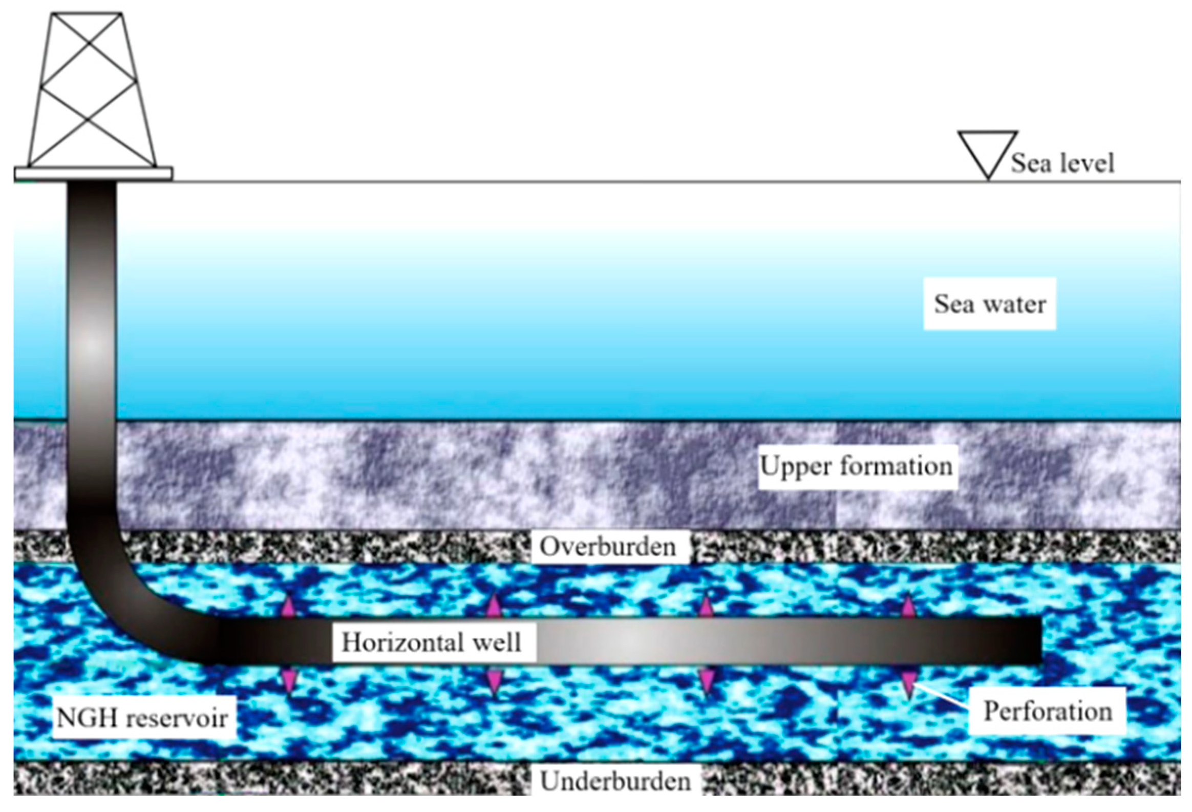
In order to deal with the problem of energy shortage, many countries make much account of the exploration and development of NGH in the world. NGH is mainly distributed in the seabed’s shallow layer and can exist stably in an environment of low temperature and high pressure. In order to increase the contact area between the well and the NGH reservoir and improve the exploitation efficiency, horizontal well drilling is often used to exploit NGH. Drilling for NGH is a complex process that requires the establishment of a successive pipeline from the ground to a reservoir for gas production, complex fluid injection, or reservoir monitoring and evaluation [11,12,13]. Figure 3 is the schematic diagram of NGH drilling with horizontal wells.
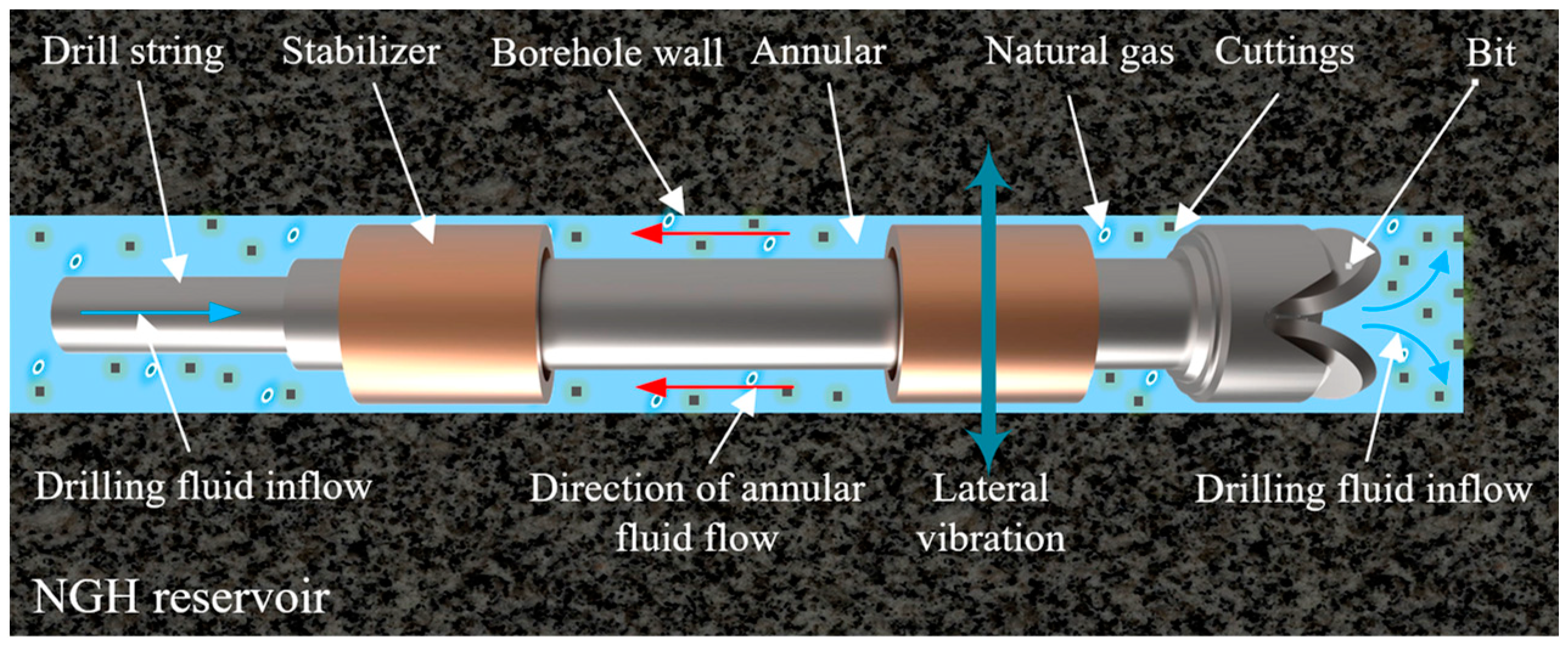
In the process of drilling horizontal wells to extract NGH, the complex drilling environment will change the nature of the NGH reservoir, resulting in the decomposition of NGH to produce a large amount of gas (mainly natural gas). The gas flows into the annular (the interspace between the drill string and the wellbore) along with the drilling fluid, making the fluid in the annular become a gas–liquid two-phase flow with a complex variation in the characteristic parameters of the pipe flow. In the meantime, the properties of drilling fluid change due to the addition of gas, leading to severe lateral vibrations of the drill string. Meanwhile, the severe vibration of the drill string will change the environment of the NGH reservoir and accelerate the decomposition of NGH. This drilling process is depicted in Figure 4. In addition, a too intense drill string vibration can easily cause a formation collapse and other serious drilling accidents. The drill string is an indispensable part of the drilling process, and also the key factor that decides the success or failure of the drilling process [14,15,16,17]. The vibration reduction in the drill string mainly depends on the annular fluid, as, in the process of NGH drilling, the decomposition of NGH changes the nature of the annular fluid. This produces a great effect on the lateral vibration of the drill string, which leads to a drill string stress mutation caused by a bigger alternating load that can prematurely invalidate the drill string, greatly increasing the difficulty and cost of drilling.
The failure of the drill string is always a difficult challenge in oilfield drilling, and the main reason for drill string failure is the violent vibration of the drill string. In recent years, many scholars have completed a mass of studies on the transverse vibration of the drill string in energy exploitation. In order to study the complex drilling process, a large number of linear and nonlinear models have been established. In continuous research, these models are widely used [18,19]. Among the early studies, it is worth noting that Huang and Mclvor studied the transverse vibration of a long vertical drill string in a plane and the coupled axial and transverse nonlinear vibration of the drill string under dynamic load, successfully applying the Galerkin method [20,21]. The Galerkin approximation method is useful for calculating nonlinear drilling models [22]. Wang et al. studied the dynamics of the drill string, considering the coupling between the drill string and drilling fluid and the influence of support stiffness [23]. Paidoussis et al. and Moditis et al. considered the drill string as an elastic cantilever suspended in a rigid outer tube with a large diameter. The dynamic characteristic of the drill string with axial flow inside and outside it has been studied, and a kinematic model has been established [24,25]. Huo et al. and Zhu et al. considered the nonlinear coupling of the axial and transverse displacements of rotating unfolded beams and studied the vibration behavior of drill strings more accurately and comprehensively [26,27]. Considering the axial, torsional, and transverse vibrations of the drill string, Zhang derived a fully coupled finite element equation of the drill string and numerically simulated the stick–slip and rotational vibrations [28]. Volpi et al. established a lumped parameter model to study the coupled torsional–transverse vibrations of the drill string [29]. Yigit et al. studied the lateral vibration of a non-rotating drill string by considering the impact between the drill string and the well wall and the existence of drilling fluid. The drill string is simulated as a thin beam with simple support [30].
The influence of the fluid character of drilling fluid on drill string vibration has been studied extensively [31,32,33,34]. Ytrehus et al. and Chang et al. investigated the shake of the drill string in drilling by changing the properties of drilling fluid [35,36]. Yang et al. researched the influence of drilling fluid on the transverse vibration frequency of the drill string through simulation and experiment [37]. A lot of experts have used numerical methods to study the effect of the annular fluid type and properties on the pressure drop [38,39,40]. Lian et al. combined natural gas drilling with a horizontal well, established a theoretical model of the drill string dynamics for gas drilling, and deduced nonlinear dynamic equations to research the dynamic response of the drill string [41]. Khajiyeva et al. derived the kinetic equation of the lateral vibration of the drill string and studied the influence of annular gas parameters on the transverse vibration of the drill string [42]. Many experts have studied the loss of pressure of the annular multiphase flow under different flow patterns by means of experiment and simulation [43,44,45]. Zhou et al. studied the transient flow law of annular air–liquid two-phase flow through numerical simulation. [46].
In conclusion, most studies have only researched the effect of the flow in the drill string and the single-phase fluid (gas or liquid) in the annular on the transverse vibration of the drill string and did not consider the influence of the presence of both gas and fluid in the annular on the lateral vibration of the drill string. Although a few experts have studied the flow feature of annular two-phase flow, they have not studied the influence of two-phase flow on the transverse vibration of the drill string.
In this paper, the nonlinear lateral vibration of the drill string under the coupled action of gas–liquid two-phase flow is researched, and the dynamic theoretical model of the lateral vibration of the drill string is derived. Through experiments and by solving equations of motion, the effect of fluid velocity and gas holdup in the annular on the lateral vibration of the drill string is analyzed. In order to facilitate the establishment of and solution by the mathematical model, the annular fluid was simplified, and the drilling mud, free gas, cuttings, and probably some hydrate particles in the annular fluid were not considered. It was assumed that the annular fluid only included gas and liquid, and the two were considered to be evenly mixed.

2. Derivation of the Lateral Vibration Model of the Drill String System

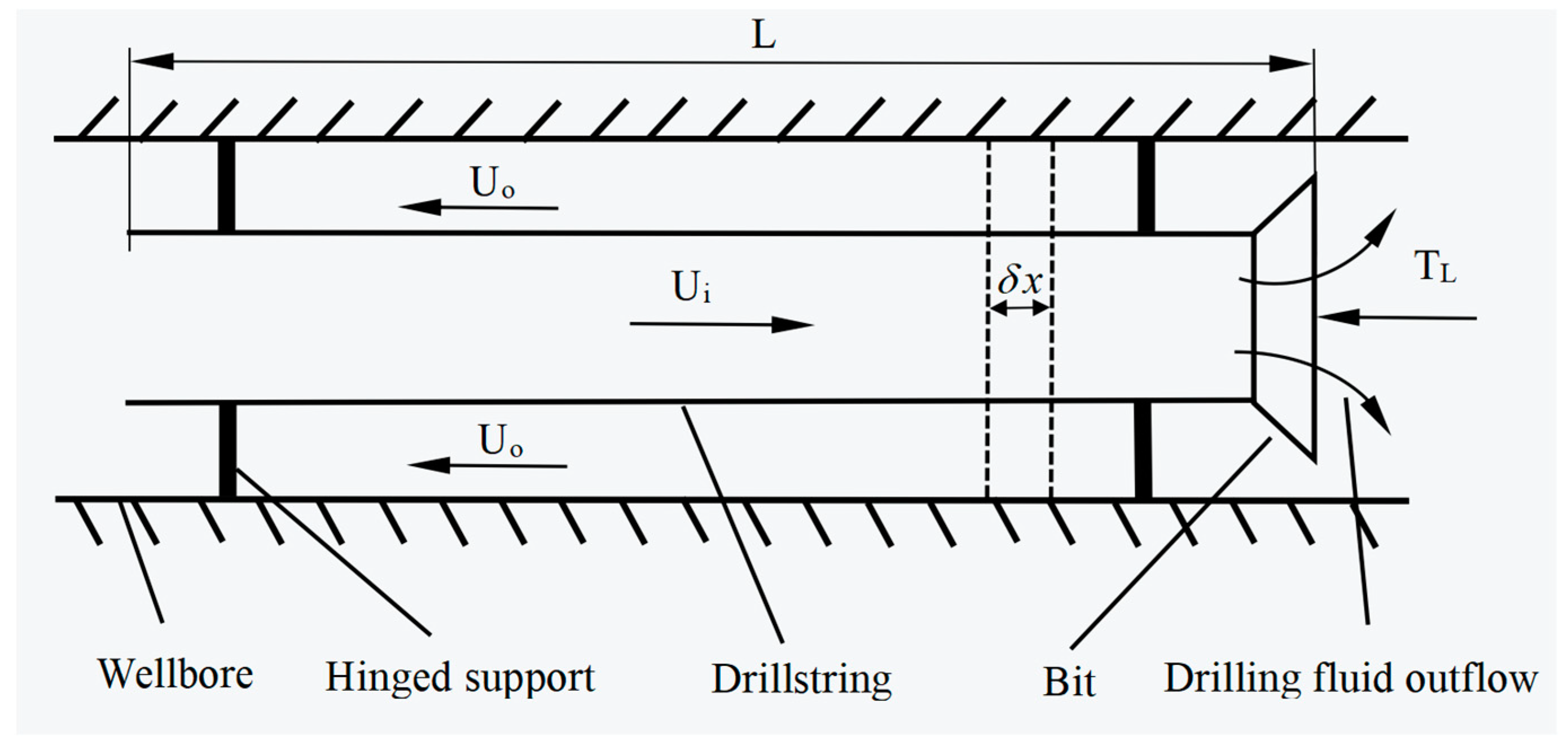
In this part, a specific dynamics model is obtained. The simplified mechanical model of the drill string in horizontal wells is shown in Figure 5. It is assumed that the drill string is a continuous elastomer of an equal section of length L, and the two ends of the drill string are fixed with hinge supports. There is an incompressible liquid with a flow rate Ui in the drill string. The liquid flows through the bottom of the drill string and mixes with the gas decomposed by NGH to become a gas–liquid two-phase flow, which then flows into the annular at a flow rate Uo. Due to the bit constantly cutting rock while drilling, there is an axial force TL at the bottom of the drill string. Next, the drill string element, the fluid element in the drill string, and the fluid element in the annular with a length of δx will be intercepted in the mechanical model shown in Figure 5, and the lateral vibration governing equation of the drill string system will be established based on the loads and interaction forces of these three elements.

2.1. Force Analysis of Drill String Element

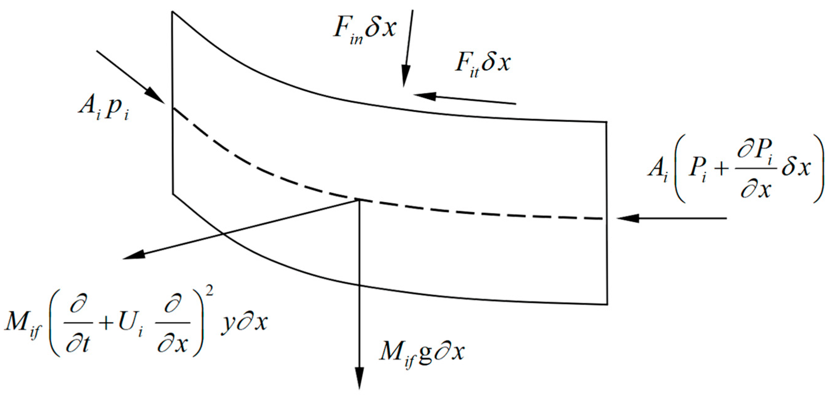
The force of the drill string element is shown in Figure 6.
According to the force of the drill string element, the balance equation of the force in the x and y directions is as follows:
T x + x Q y x + F i t F i n y x F e t + F e n y x = 0
M t 2 y t 2 x T y x Q x F i n F i t y x + F e n + F e t y x = 0
where Q is the lateral shear force; Mt is the mass per unit length of the drill string; T is the axial tension; Fin and Fen are the normal hydrodynamic forces generated by the flow inside and outside the drill string, respectively; Fit and Fet are the tangential hydrodynamic forces generated by the flow inside and outside the drill string, respectively; and y is the lateral deflection.
According to Euler–Bernoulli beam theory:
Q = x E I 2 y x 2
where E is the elastic modulus of the drill string, I is the moment of inertia of the drill string.
By substituting Equation (3) into Equations (1) and (2) and ignoring high-order small quantities, we can obtain
T x + F i t F i n y x F e t + F e n y x = 0
E I 4 y t 4 + M t 2 y t 2 x T y x F i n F i t y x + F e n + F e t y x = 0

2.2. Force Analysis of Fluid Element in Drill String

The fluid elements in the drill string are affected by gravity, pressure, and the interaction forces with the drill string, as shown in Figure 7.
According to the force of the fluid element in the drill string, the balance formula of the force in the x and y directions is as follows:
F i t F i n y x = A i P i x
F i n F i t y x = x A i P i y x + M i f 2 y t 2 + 2 U i 2 y x t + U i 2 2 y x 2
where Ai is the internal cross-sectional area of the drill string, Pi is the pressure of the fluid in the drill string, and Mifg is the gravity of the fluid in the drill string.

2.3. Force Analysis of Annular Fluid Element

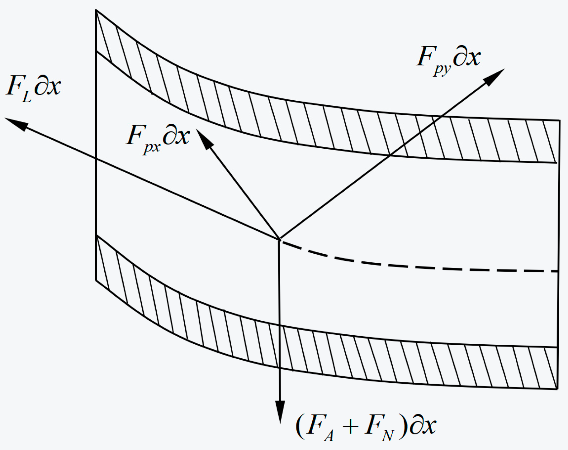
The force condition of the annular fluid is very complex, so the force balance equation cannot be established directly. The annular fluid forces acting on the drill string are the component forces caused by pressure and gravity, Fpx and Fpy; the frictional viscous forces, FL and FN; and the lateral inviscid hydrodynamic force, FA. The force diagram of the annular fluid element is shown in Figure 8.

2.4. Forces Fpx and Fpz Caused by the Pressure and Gravity

Assuming the annular pressure Po changes linearly in the x direction, from hydrostatics and frictional pressure loss, we can obtain [47]
F p x = x P o A o + A o P o x
F p y = A o x P o y x
where Ao is the external cross-sectional area of the drill string. Since the drill string is of an equal section, ∂Ao/∂x = 0, and Fpx = 0.
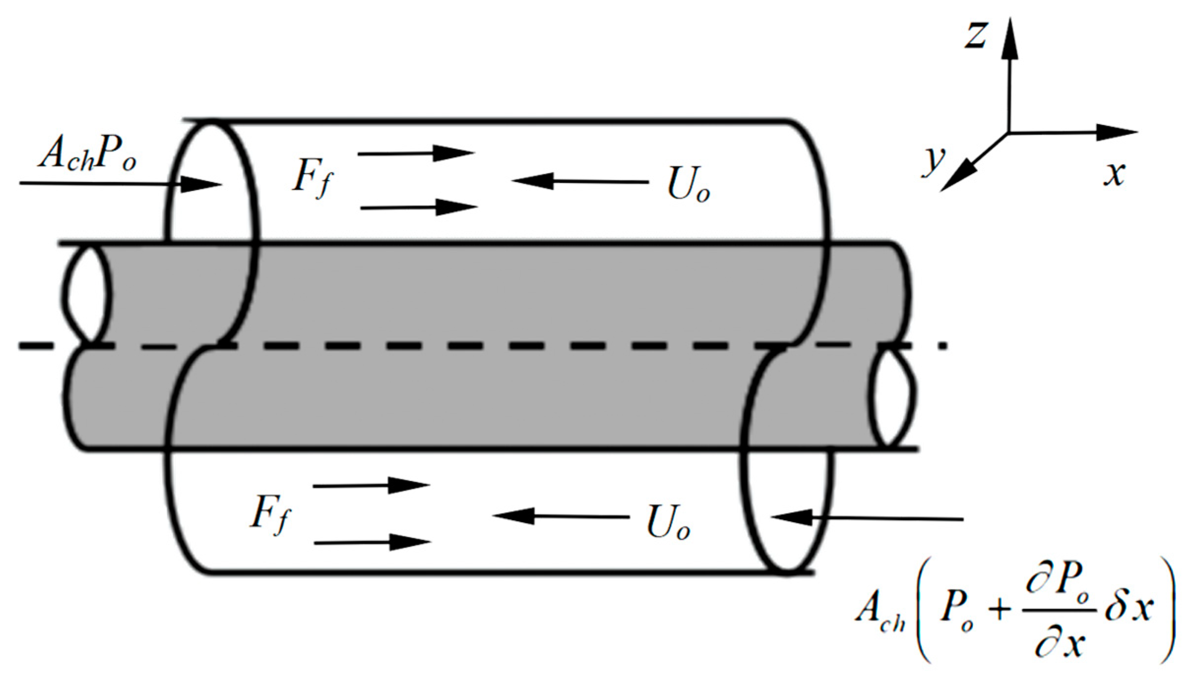
The force diagram of the annular fluid element in x direction is shown in Figure 9. The expression of annular pressure Po can be obtained by establishing the force balance equation for the annular fluid.
The force balance equation of the annular fluid element in the x direction is as follows:
A c h p o + F f δ x A c h p o + p o x δ x = 0
F f = F L S t o t S o
where Ach = π( D c h 2 D o 2 )/4 is the cross-sectional area of the annular, Do is the external diameter of the drill string, Dch is the internal diameter of the wellbore, Stot = π(Dch + Do) is the total wetted area, So = πDo is the wet area outside the drill string element, and Ff is the total friction.
Combining Equations (10) and (11) and integrating x, we can obtain
P o = F L D o A o D h x
where Dh = 4Ach/Stot is the hydraulic diameter of the annular channel flow.

2.5. Inviscid Hydrodynamic Force

According to Hannoyer et al. and Paidoussis et al., the transverse inviscid hydrodynamic form of the fluid element is [24,47]
F A = χ t U o x ρ o A o y t U o y x
χ = D c h / D o 2 + 1 D c h / D o 2 1
where ρo is the fluid density in the annular, and χ is the coefficient of the added mass.

2.6. Forces of Frictional Viscous

The normal and tangential viscous friction forces of the annular fluid acting on the drill string can be calculated by the following equation [48]:
F N = 1 2 C f ρ o D o U o y t U o y x + k y t
F L = 1 2 C f ρ o D o U o 2
where Cf and k are the coefficients of the viscous damping, and the k is as follows:
k = 2 2 S 1 + γ ¯ 3 1 γ ¯ 2 2 ρ o A o Ω
where S = Ω r o 2 /v is the Stokes number, Ω is the circumferential vibration frequency, v is the kinematic viscosity of annular flow, ro = Do/2, and γ = Do/Dch.

2.7. Force Balance Equation of Annular Fluid Element

By combining Equations (8), (9), (13), (15) and (16), the force of the annular fluid elements on the drill string can be expressed as
F e t F e n y x = F L + F p x
F et y x + F e n = F A F p y + F L y x + F N

2.8. Lateral Vibration Model of Drill String System

By substituting Equations (7) and (19) into Equation (5), the dynamic equation of the lateral vibration of the drill string system can be obtained as follows:
E I 4 y t 4 + M t 2 y t 2 x T A i p i + A o p o y x + M i f 2 y t 2 + 2 U i 2 y x t + U i 2 2 y x 2 + χ ρ o A o 2 y t 2 2 U o 2 y x t + U o 2 2 y x 2 + 1 2 C f ρ o D o U o y t + k y t = 0
After substituting Equations (6), (12), (15), (16) and (18) into Equation (4), (T − AiPi + AoPo) can be obtained, as shown in Equation (21):
x T A i p i + A o p o 1 2 C f ρ o D o U o 2 1 + D o D h = 0
then, after integrating from x to L, this becomes
T A i p i + A o p o = T A i p i + A o p o L 1 2 C f ρ o D o U o 2 1 + D o D h ( L x )
By substituting Equation (22) into Equation (20), the final form of the lateral vibration dynamic model of the drill string system can be obtained:
E I 4 y t 4 + M t 2 y t 2 T A i p i + A o p o L 1 2 C f ρ o D o U o 2 1 + D o D h ( L x ) 2 y x 2 1 2 C f ρ o D o U o 2 1 + D o D h y x + M i f 2 y t 2 + 2 U i 2 y x t + U i 2 2 y x 2 + χ ρ o A o 2 y t 2 2 U o 2 y x t + U o 2 2 y x 2 + 1 2 C f ρ o D o U o y t + k y t = 0
Assuming that the fluid in the annular is mixed evenly and that there is no energy loss when the drilling fluid enters the annular from the bottom of the drill string system, the fluid parameters of the gas–liquid two-phase flow can be calculated by the volume averaging method [49]:
ρ o = ρ i ( 1 α ) + ρ g α U o = U i A i A c h
where α is the gas content of the annular fluid, and ρg is the density of the natural gas.

2.9. Boundary Conditions

The lateral vibration dynamic, Equation (23), is subjected to the following boundary conditions:
y ( 0 , t ) = 0 , 2 y x 2 ( 0 , t ) = 0 y ( L , t ) = 0 , 2 y x 2 ( L , t ) = 0

2.10. Dimensionless Equation of Motion

In order to solve the model of motion conveniently, it is analyzed as being dimensionless. The following dimensionless formula can be used to change the motion model into a dimensionless equation more conveniently.
ξ = x / L , η = w / L , τ = E I / 2 M t + 2 M i f + ρ o A o 1 / 2 t / L 2 u i = M i f / E I 1 / 2 U i L , u o = ρ o A o / E I 1 / 2 U o L , β o = ρ o A o / M t + M i f + ρ o A o β i = M i f / 2 M t + 2 M i f + ρ o A o , Γ = T L L 2 / E I , c f = 4 C f / π Π i L = p i L A i L 2 / E I , Π o L = p o L A o L 2 / E I , κ = k L 2 / E I 2 M t + 2 M i f + ρ o A o 1 / 2 ε = L / D o , h = D o / D h
By substituting Equation (26) into Equation (23), we can obtain
4 η ξ 4 + a 2 η τ 2 + b 2 η τ ξ + d η ξ + { c d ( 1 ξ ) ( Γ Π i L + Π o L ) } 2 η ξ 2 + e η τ = 0
a = 1 + β o ( χ 1 ) , b = 2 u i β i 1 / 2 χ u o β o 1 / 2 , c = u i 2 + χ u o 2 d = 1 2 c f ε u o 2 ( 1 + h ) , e = 1 2 c f ε u o β o 1 / 2 + κ
The corresponding boundary conditions are
η ( 0 , τ ) = 0 , 2 η ξ 2 ( 0 , τ ) = 0 η ( 1 , τ ) = 0 , 2 η ξ 2 ( 1 , τ ) = 0

3. Method of Solution

In this part, the Galerkin method is used to discretize the above motion model to obtain an ordinary differential equation. Then, the influence of annular fluid characteristic parameters on the stability of drill string system is studied by solving ordinary differential equations.

Galerkin Method

Galerkin method is an approximate solution based on eigenvalue problems of differential equations and is applicable to any beam or beam-like object subjected to fluid loads. According to Galerkin theory, the vibration of an elastic body can be decomposed into the product of a function with respect to time and a function with respect to space. Therefore, we can set the solution of Equation (27) as follows:
η ( ξ , τ ) = Φ q T
where Φ = [Φ1, Φ2, Φ3, …,ΦN] is the mode function satisfying the boundary conditions of displacement and force, and q = [q1, q2, q3, …,qN] is discrete system’s generalized coordinates.
By substituting Equation (30) into Equation (27) and using the orthogonality of modal function, after integrating in the interval [0, 1], the equation can be written as follows:
M q ¨ + C q ˙ + K q = 0
where M is a matrix of mass: Mij = aδij; C is a matrix of damping: Cij = bΛij + eδij; K is a matrix of stiffness: Kij = (iπ)4δij − (c + d)()2δij + d(Λij + Dij); δij is Kronecker delta; and Λij and Dij are, respectively:
Λ i j = i j i 2 j 2 1 ( 1 ) i + j i j 0 i = j D i j = 4 i j 3 ( i 2 j 2 ) 2 1 ( 1 ) i + j i j ( i π ) 4 4 i = j
The solution of Equation (31) can be set as:
q = q ¯ e ω τ
By substituting Equation (33) into Equation (31), we can obtain:
ω 2 M + ω C + K q ¯ = 0
Equation (34) is a generalized eigenvalue problem, and the stability of the drill string system could be determined by calculating the complex eigenvalues ω of the matrix E. The expression of matrix E is as follows:
E = 0 I M 1 K M 1 C
where I is the identity matrix. The relationship between the stability of the system and the generalized eigenvalues ω of matrix E is as follows: Re(ω) and Im(ω) are the real and imaginary parts of ω, respectively. Re(ω) is related to modal damping of the system, Im(ω) is related to the natural frequency of the system, and, when the value of Im(ω) decreases, the stability of the drill string system decreases. When Re(ω) < 0 and Im(ω) ≠ 0, the drill string system is in steady state. In the case of Re(ω) ≥ 0 and Im(ω) ≠ 0, flutter instability occurs, and the corresponding fluid velocity Uo, when Re(ω) increases to zero from negative values, is called the critical flutter velocity. Buckling instability happens when Im(ω) = 0, and the corresponding fluid velocity Uo is called the critical buckling velocity [50,51].

4. Numerical Results

In this section, MATLAB software is used to solve the generalized eigenvalue of matrix E. By changing the velocity and gas content of the annular fluid, the effect of the fluid peculiarity of the annular fluid on the stability of the horizontal drill string system can be found. The drill string system parameters used in the above study are shown in Table 1 [52].

4.1. Effect of Annular Fluid Velocity on the Stability of Drill String System

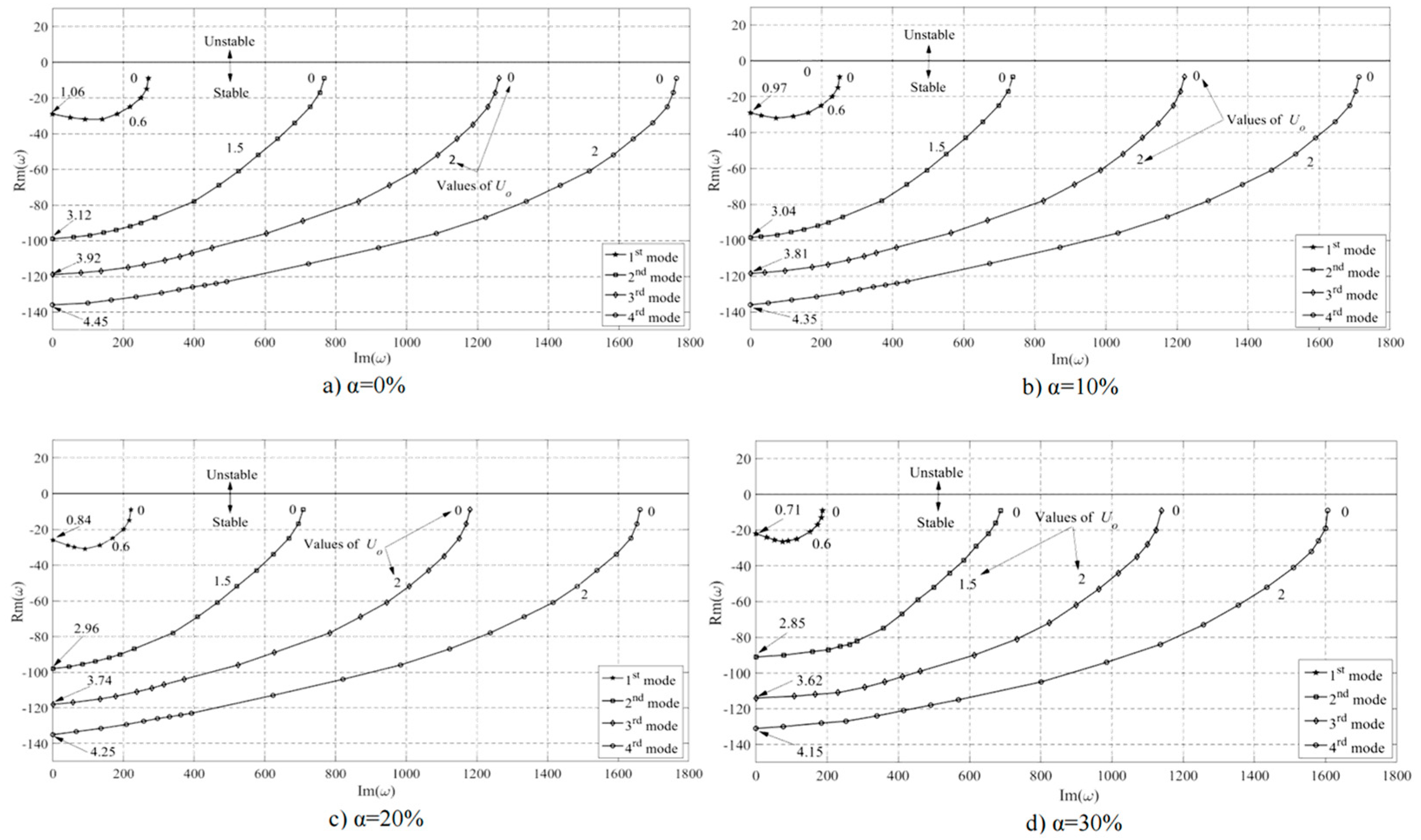
As shown in Figure 10, the changes of the first four order complex frequencies of the drill string system, with an increase in the fluid velocity of the annular, were calculated when the annular fluid gas content ranged from 0% to 30%. The results show that the Re(ω) value is always less than zero, and the Im(ω) value gradually decreases when the fluid velocity and gas content of the annular fluid increase. When the Im(ω) value decreases from positive to 0, drill string system buckling occurs. This means that with an increase in annular fluid velocity and gas content, the transverse vibration frequency of the drill string system decreases.

4.2. Effect of Annular Fluid Gas Content on Stability of Drill String System

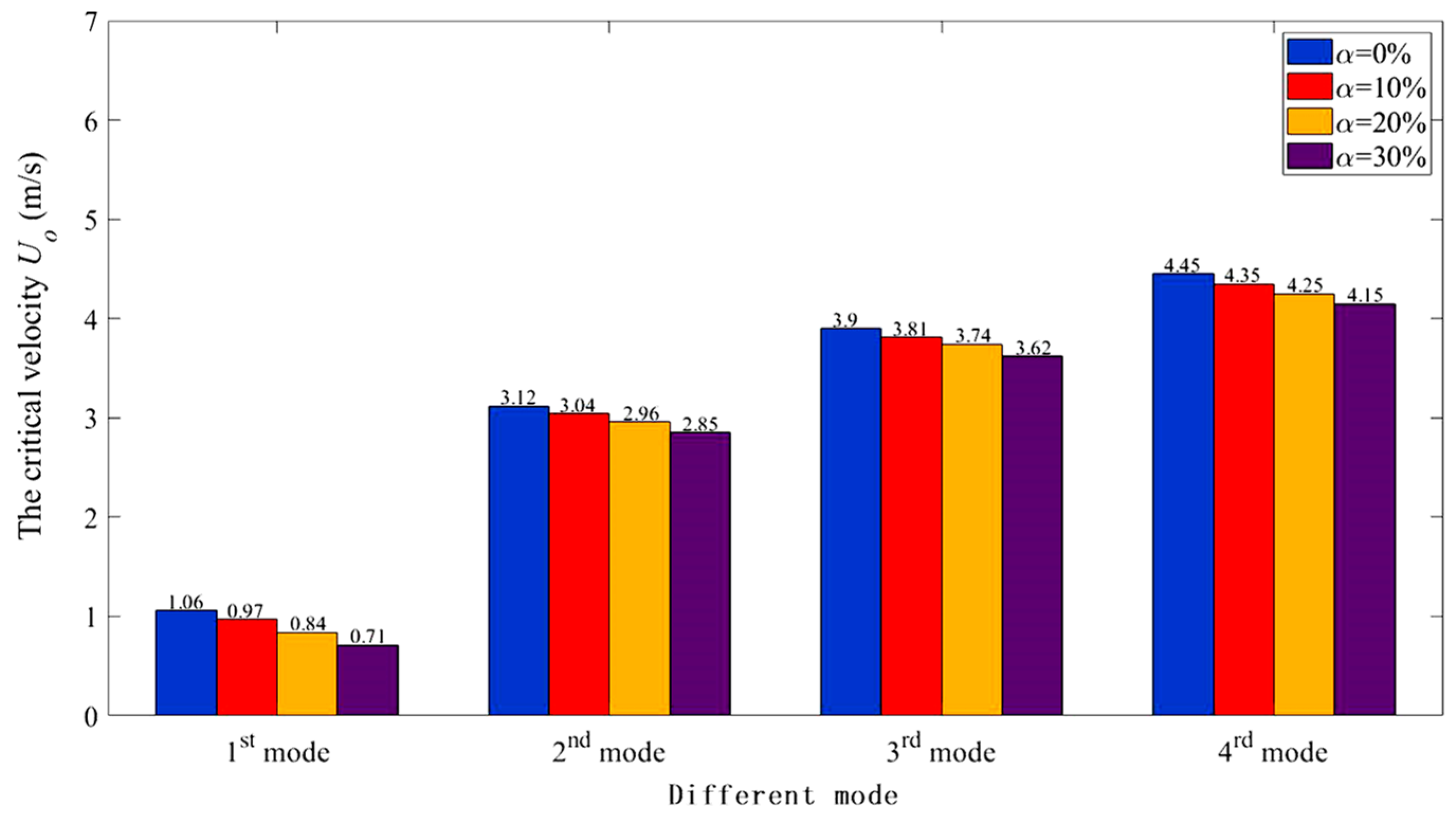
As is shown above, when Im(ω) = 0, the drill string system will demonstrate buckling instability, and the corresponding annular fluid velocity is the critical buckling velocity of the drill string system. As shown in Figure 11, in order to observe the influence of the gas content on the stability of the drill string system, the critical velocity Uo of the annular fluid was calculated when buckling instability occurred in the first four modes of the drill string system with different gas content. The results show that with an increase in annular fluid gas content, the critical velocity of the first four orders of the drill string system decreases, that is, the stability of drill string system decreases along with an increase in the annular fluid gas content.
As shown in Figure 12, in order to further understand the relationship between annular fluid velocity and annular fluid gas content, the complex frequency change of the drill string system under the same annular flow velocity was calculated. We found that at the same annular fluid velocity, the Im(ω) decreases with an increase in the gas content. This means that at the same annular fluid velocity, the stability of the drill string system deteriorates as the annular fluid gas content increases.
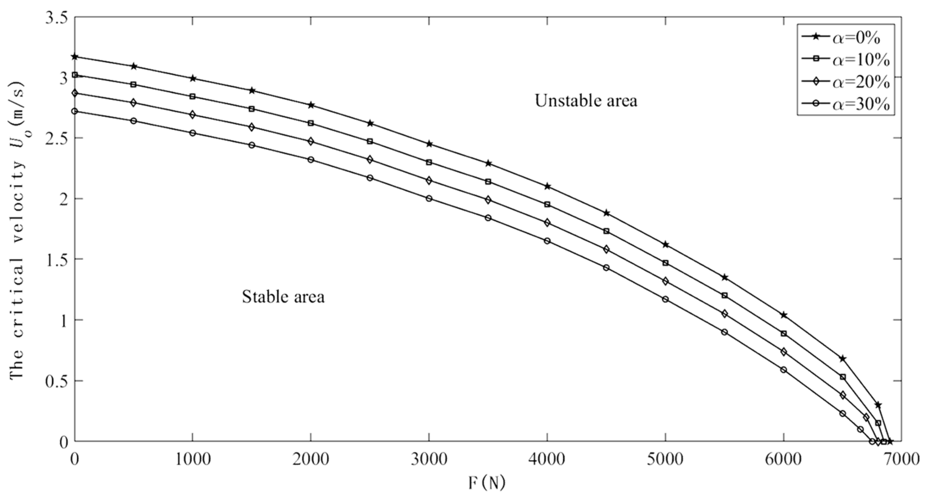
In order to exclude the effect of the force at the bottom of the drill string, the critical flow rate of the annular with gas content ranging from 0–30% under different bottom forces was solved; the result is shown in Figure 13. We found that the stability area of the drill string system decreases with the increase in gas content under different bottom forces.

5. Experimental Study

In this part, the effects of annular fluid velocity and gas content on the transverse vibration of a horizontal drill string are studied by using experimental equipment.

5.1. Experimental Apparatus and Procedure

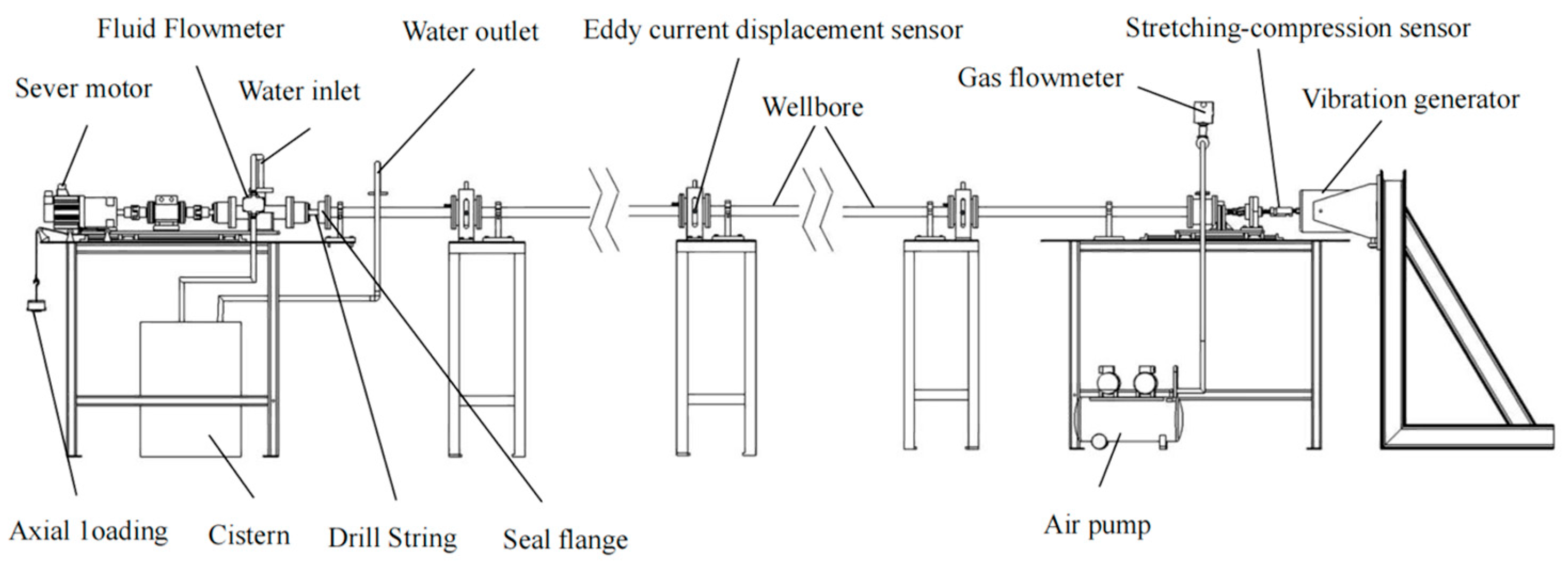
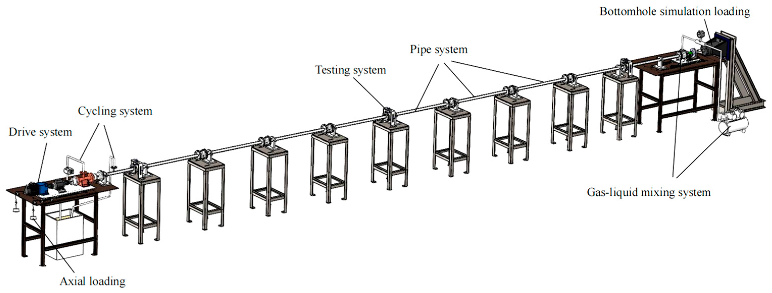
According to the similitude principle, the experiment device was developed to simulate the working condition of horizontal drilling with gas. The structure diagram of the experiment device is shown in Figure 14 and Figure 15. The experiment device was mainly composed of six systems, which were the drive system, pipe system, circulation system, loading system (including axial load and bottomhole simulation load), gas–liquid mixing system, and test system.
We use the dimension analysis method to derive the similarity criterion. The dimensionality of the parameters and the dimensionality matrix of the system are shown in Table 2 and Table 3, respectively.
We can organize the dimensionality matrix of the system into the following equations:
a 2 + a 3 + a 4 + a 6 = 0 a 1 a 2 3 a 3 + 4 a 5 + a 6 = 0 2 a 2 2 a 6 a 7 = 0
The following equations can be obtained from the π matrix:
π 1 = l 3 ρ 1 = m l 3 ρ π 2 = l 4 I = I l 4 , π 3 = l 2 E F = F l 2 E π 4 = l E 0.5 ρ 0.5 φ = l φ ρ E
According to the similarity theory, the actual drill string size corresponding to this experimental equipment was as follows: outer diameter 127 mm, inner diameter 108 mm, and total length 100 m. In addition, all physical quantities with length units should abide by the length similarity ratio. Taking the length similarity ratio as c_l = 1:10, the outer diameter of the experimental drill string was 15 mm, the inner diameter was 10 mm, and the total length was 10 m. In practice, the drill string was made of alloy steel with a density of ρ = 7800 kg/m3 and an elastic modulus of E = 207 GPa. The experimental material should have a stress–strain curve similar to that of the actual material. According to the density similarity ratio c_ρ = 0.14 and the elastic modulus similarity ratio c_E = 0.011, ABS engineering plastic was selected as the material for the drill string in the experiment. The elastic modulus of the ABS engineering plastic was 2.3 GPa, and the density was 1100 kg/m3.
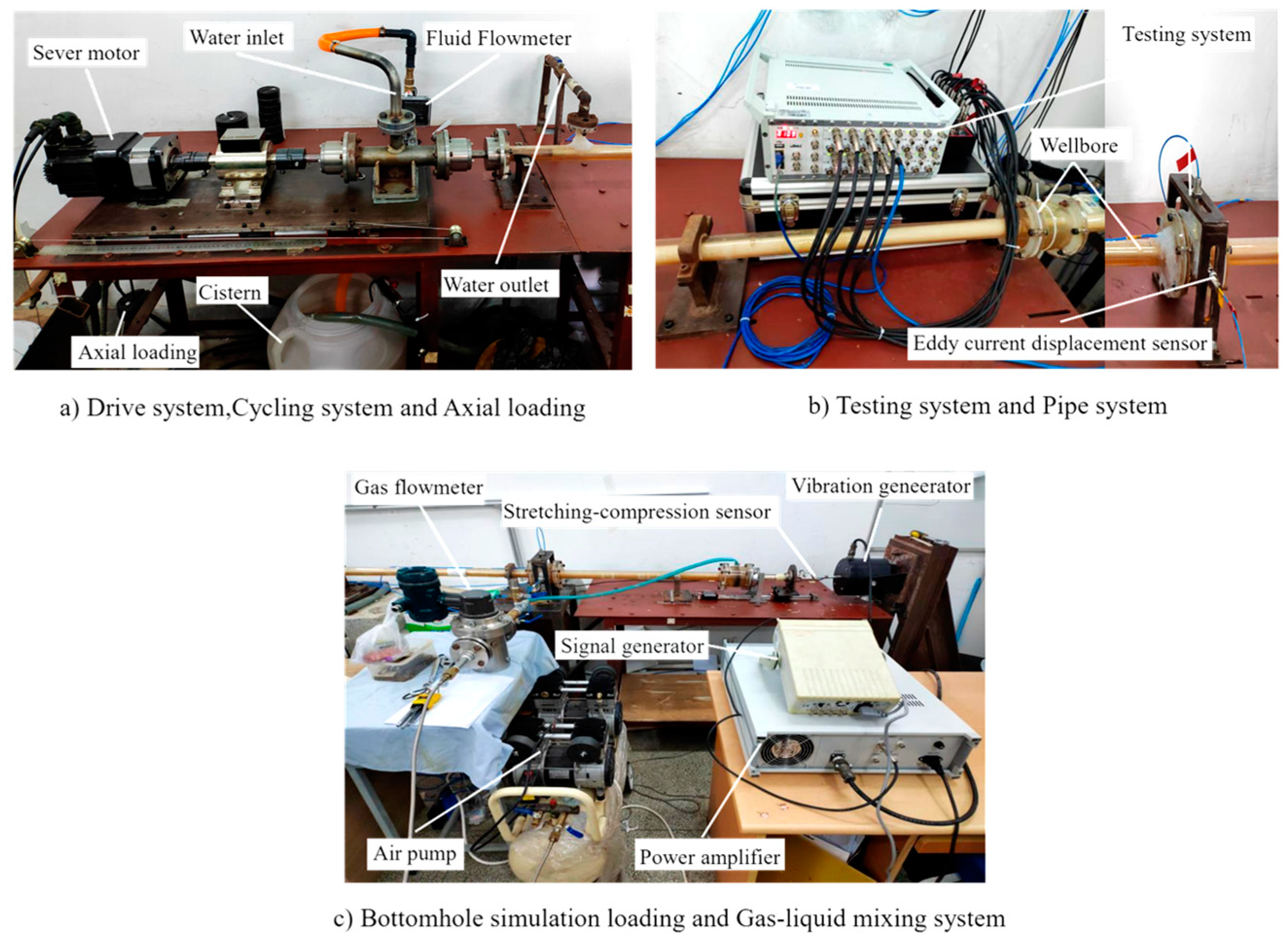
In the simulation experiment, the servo motor of the driving system provided the speed for the drill string, the water in the cistern entered the drill string; flowed into the annular through the water inlet of the cycling system, and then returned to the cistern through the outlet of the cycling system; and the velocity of the annular fluid as determined by the liquid flow meter in the cycling system. The drilling string and borehole were simulated by the pipe string system, and the axial load and bottomhole load on the drilling string were simulated by the loading system. The gas–liquid mixing system was used to inject gas into the end of the wellbore to simulate the working condition of the gas produced by the decomposition of NGH during the exploitation, and the gas content in the annular as determined by the gas flow meter. Finally, the voltage signal as obtained by the eddy current sensor arranged horizontally in the testing system, and the voltage signal was converted into the lateral displacement data of the drill string. The experimental device could totally simulate the work condition when drilling horizontal wells to extract NGH, and the actual pictures of each system are shown in Figure 16.
Next, the control variable method was used to conduct experiments. Three experiments were conducted under each condition, and the duration of each experiment was one minute. By observing and comparing the results of the three experiments under the same conditions (the waveform of drill string transverse displacement), after a short irregular fluctuation, the waveform of the three experiments was almost the same. Finally, the section with the most consistent lateral displacement waveform of drill string in the three experiments was selected as the experimental results.

5.2. Experiment Result

In order to verify the reliability of the effect of annular fluid velocity on the transverse vibration of the drill string obtained from the numerical results above, the experiment was carried out by using the control variable method. In this experiment, the rotational speed of the drill string (180 rad/min), axial load (2 kg), gas content (0%), frequency of the vibration generator (12 Hz), and power amplifier of the vibration generator (5 V) were kept unchanged, so only the velocity of the annular fluid was changed (from 0.3 m/s to 1.2 m/s). The influence of the annular fluid velocity on the transverse vibration of drill string was obtained by comparing the experimental results of different annular fluid velocities.
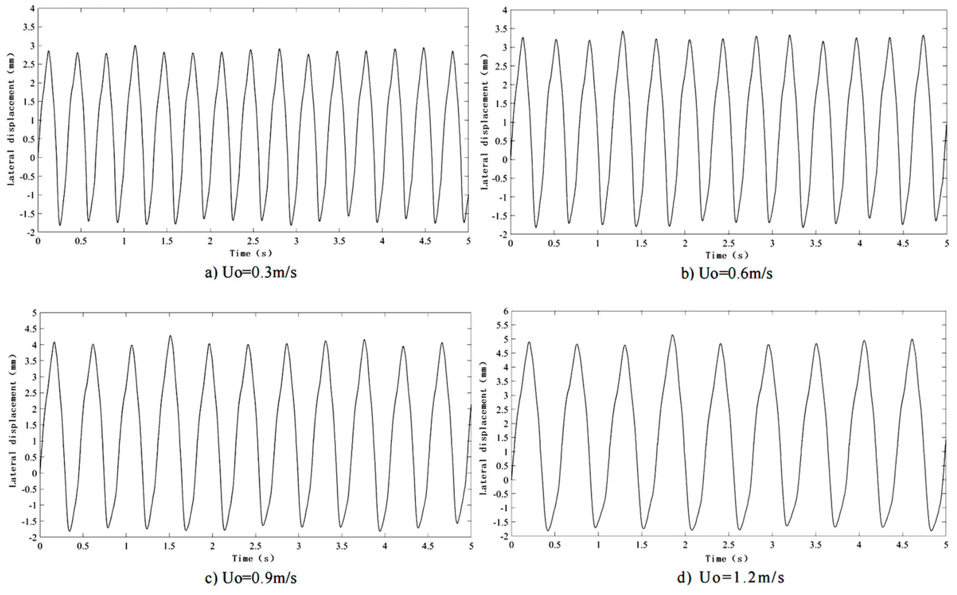
Figure 17 shows the change of the lateral displacement of the drill string with time at different annular flow rates when the annular fluid gas content is 0%. Figure 17a–d, respectively, correspond to annular flow rates of 0.3 m/s, 0.6 m/s, 0.9 m/s, and 1.2 m/s, and the time to intercept the experimental data under each experimental condition is 5 s. By observing and comparing Figure 17a–d, the frequency of the lateral vibration of the drill string gradually decreases, and the displacement of the lateral vibration of the drill string increases by about 0.5–2 mm. This also indicates that when the gas content of the annular fluid is 0%, the transverse vibration frequency of the drill string decreases and the amplitude increases with an increase in the annular fluid velocity.
Then, in order to verify the reliability of the influence of annular gas content on the lateral vibration of drill string obtained from the above numerical results, the control variable method was used again to carry out experiments. In the following experiments, the annular fluid velocity was kept at 0.3 m/s, the gas content of the annular fluid was changed (from 10% to 30%), and other experimental parameters were kept consistent with those in the previous set of experiments.
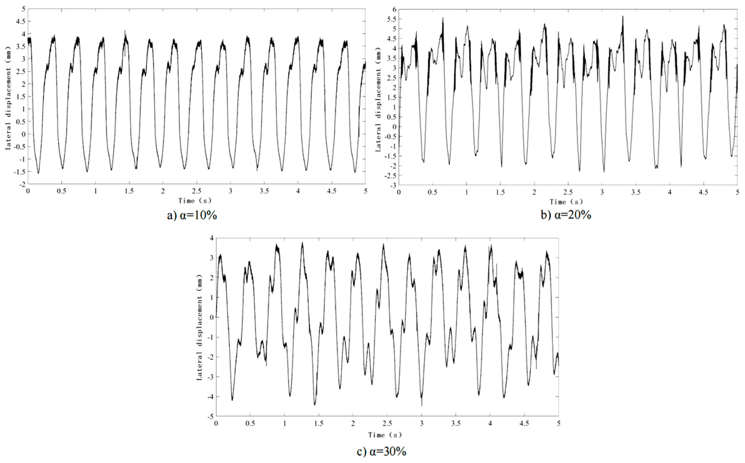
As shown in Figure 18, using the above experimental parameters, the results of the lateral displacement of drill string changing with time under different annular fluid gas content were obtained. As the experimental conditions corresponding to Figure 17a are as follows: annular fluid flow rate is 0.3 m/s and gas content is 0%, a comparative analysis can be made between Figure 17a and Figure 18a–c, and the gas content values of annular fluid corresponding to Figure 17a and Figure 18a–c are 0%, 10%, 20% and 30% respectively. It can be seen from Figure 17a and Figure 18a–c that with an increase in annular fluid gas content, the transverse vibration frequency of the drill string decreases, and the transverse vibration amplitude of the drill string increases. When there is no gas in the annular, the lateral displacement of the drill string changes periodically with time. However, with an increase in annular gas content, the transverse displacement of the drill string changes more and more irregularly with time, that is, with an increase in the gas content of the annular fluid, the periodic change of the transverse vibration of the drill string becomes more and more complex.
According to the above experimental results, with an increase in annular fluid velocity and gas content, the lateral vibration frequency of the drill string decreases, the transverse vibration amplitude of the drill string increases, that is, the stability of the drill string system decreases, which is consistent with the results obtained by the mathematical model above, further proving the reliability of this study.

6. Discussion

In this study, the effect of annular fluid on the transverse vibration of a horizontal drill string was studied by establishing a mathematical model, and the results of the numerical solution were verified by experiments. In the mathematical model, the influence of annular fluid on horizontal drill string stability was researched by changing the fluid velocity and gas content of the annular fluid. To verify the reliability of the numerical solution, relevant experiments were carried out by changing the fluid velocity and gas content of the annular fluid. In the experimental results, we observed the transverse vibration amplitude and frequency of the horizontal drill string, to determine how the stability of the drill string changes when the fluid velocity and gas content of the annular are changed. We compared the numerical results with the experimental results, and we found that the influence of annular fluid on drill string stability, obtained from the numerical results, is consistent with the experimental results.

7. Conclusions

In this paper, the nonlinear mathematical model of a drill string’s lateral vibration was established, and the effect of annular fluid characteristics on drill string transverse vibration was studied. The results obtained by numerical simulation were verified by experiments. The following results can be concluded: 1. With an increase in annular fluid velocity, the stability of the drill string system decreases, the frequency of the drill string lateral vibration decreases, and the amplitude of the drill string lateral vibration increases, when there is no gas in the annular. 2. When the annular fluid velocity is constant, with an increase in annular fluid gas content, the stability of the drill string system decreases, the periodic change of the drill string transverse vibration becomes more and more complicated, and the amplitude of the drill string transverse vibration increases. 3. The transverse vibration frequency of the drill string changes more quickly when the flow rate of the annular fluid increases than when the annular gas content increases. Therefore, the influence of annular fluid flow velocity on the lateral vibration of the drill string is greater than that of annular fluid gas content on the transverse vibration of the drill string.

Author Contributions

Conceptualization, F.R. and B.W.; methodology, F.R. and B.W.; software X.M. and L.W.; validation, X.M. and L.W.; formal analysis, F.R.; investigation, L.W.; resources, B.W.; data curation, L.W.; writing—original draft preparation, L.W. and B.W.; writing—review and editing, L.W. and B.W.; visualization, L.W.; supervision, F.R. and B.W.; project administration, F.R. and B.W.; funding acquisition, F.R. and B.W. All authors have read and agreed to the published version of the manuscript.

Funding

This research was funded by the National Natural Science Foundation of China under Grant No. 11902072, the China Postdoctoral Science Foundation under Grant No. 2020M670880, the Natural Science Foundation of Heilongjiang Province under Grant No. LH2019A003, the Heilongjiang Postdoctoral Science Foundation under Grant No. LBH-Z20047, and the Natural Science Foundation of Northeast Petroleum University under Grant No. 2019QNL-13.

Data Availability Statement

Not applicable.

Conflicts of Interest

The authors declare no conflict of interest.

Nomenclature

LLength of drill string (m)
UiDrilling fluid velocity in drill string (m/s)
UoAnnular fluid velocity (m/s)
TLAxial force at bottom (N)
QLateral shear force in the drill string (N)
MtMass of drill string element (kg)
TAxial force of drill string section (N)
yLateral deflection (m)
AiCross-sectional area of drill string internal (m2)
PiPressure of the fluid inside the drill string (Pa)
MifMass of the fluid inside the drill string (kg)
Fpx, FpyComponent forces caused by pressure and gravity (N)
FL, FNFrictional viscous forces (N)
FALateral inviscid hydrodynamic force (N)
PoAnnular pressure (Pa)
AoCross-sectional area of drill string external (m2)
AchAnnular cross-sectional area (m2)
DoDrill string outer diameter (m)
DchWellbore inner diameter (m)
StotTotal wetted area (m2)
SoWet area outside the drill string (m2)
DhHydraulic diameter of the annular channel flow
ρoGas–liquid mixture density (kg/m3)
ρiDrilling fluid density (kg/m3)
ρgNatural gas density (kg/m3)
χAdded mass coefficient (-)
SStokes number (-)
Cf, kViscous damping coefficients (-)
vKinematic viscosity of annular fluid (m2/s)
ΩCircular frequency of oscillation (rad/s)
αGas content (-)
FinNormal hydrodynamic force generated by internal flow (N)
FitTangential hydrodynamic force generated by internal flow (N)
FenNormal hydrodynamic force generated by external flow (N)
FetTangential hydrodynamic force generated by external flow (N)
EElastic modulus of drill string (GPa)
IMoment of inertia of drill string (m4)
FfThe total friction force applied to the drill string element (N)
MMass matrix
CDamping matrix
KStiffness matrix

References

  1. Matsuzawa, M.; Terao, Y.; Hay, B.; Wingstrom, L.; Duncan, M.; Ayling, I. A completion system application for the world’s first marine hydrate production test. In Proceedings of the Offshore Technology Conference, Houston, TX, USA, 5–8 May 2014. [Google Scholar]
  2. Seales, M.; Silva, J.M.-D.; Ertekin, T.; Wang, J.Y. An Investigation Into the Occurrence of Hydrate-Bearing Sediments Offshore the East Coast of Trinidad and Tobago. SPE J. 2016, 21, 1782–1792. [Google Scholar] [CrossRef]
  3. Han, D.; Wang, Z.; Song, Y.; Zhao, J.; Wang, D. Numerical analysis of depressurization production of natural gas hydrate from different lithology oceanic reservoirs with isotropic and anisotropic permeability. J. Nat. Gas Sci. Eng. 2017, 46, 575–591. [Google Scholar] [CrossRef]
  4. Yu, L.; Xu, Y.; Gong, Z.; Huang, F.; Zhang, L.; Ren, S. Experimental study and numerical modeling of methane hydrate dissociation and gas invasion during drilling through hydrate bearing formations. J. Pet. Sci. Eng. 2018, 168, 507–520. [Google Scholar] [CrossRef]
  5. Fang, T.; Ren, F.; Liu, H.; Zhang, Y.; Cheng, J. Progress and development of particle jet drilling speed-increasing technology and rock-breaking mechanism for deep well. J. Pet. Explor. Prod. Technol. 2021, 12, 1697–1708. [Google Scholar] [CrossRef]
  6. Michael, D.M.; Arthur, H.J. Exploration and Production of Oceanic Natural Gas Hydrate, 1st ed.; Springer International Publishing: Cham, Switzerland, 2016; pp. 9–11. [Google Scholar]
  7. Farahani, M.V.; Guo, X.; Zhang, L.; Yang, M.; Hassanpouryouzband, A.; Zhao, J.; Yang, J.; Song, Y.; Tohidi, B. Effect of thermal formation/dissociation cycles on the kinetics of formation and pore-scale distribution of methane hydrates in porous media: A magnetic resonance imaging study. Sustain. Energy Fuels 2021, 5, 1567–1583. [Google Scholar] [CrossRef]
  8. Farahani, M.V.; Aliakbar, H.; Yang, J.H.; Bahman, T. Insights into the climate-driven evolution of gas hydrate-bearing permafrost sediments: Implications for prediction of environmental impacts and security of energy in cold regions. RSC Adv. 2021, 11, 14334–14346. [Google Scholar] [CrossRef] [PubMed]
  9. Wang, B.; Wang, L.; Liu, X.; Ren, F. Bifurcation Diagram and Dynamic Response of a Drill String Applied in NGH Drilling. Processes 2022, 10, 1111. [Google Scholar] [CrossRef]
  10. Huang, X.Z.; Du, S.H. Status and prospect supply and demand trading of global natural gas and LNG. Oil Gas Storage Transp. 2018, 38, 12–19. [Google Scholar]
  11. Du, Q.; Liu, Y.; Hou, J.; Shi, L.; Wang, W.; Zhou, K. Investigation on the Secondary Generation of Natural Gas Hydrates in Horizontal Wellbore Caused by Pressure Jump during the Depressurization Development of Hydrate Bearing Layers. Geofluids 2020, 2020, 8815455. [Google Scholar] [CrossRef]
  12. Huang, Y.F.; Yue, Z.R.; Hu, X.Y. Characteristics of AMT response of anisotropic natural gas hydrate reservoirs in permafrost regions. Chin. J. Geophys. 2018, 61, 2629–2640. [Google Scholar]
  13. Chazallon, B.; Rodriguez, C.; Ruffine, L.; Carpentier, Y.; Donval, J.-P.; Ker, S.; Riboulot, V. Characterizing the variability of natural gas hydrate composition from a selected site of the Western Black Sea, off Romania. Mar. Pet. Geol. 2021, 124, 104785. [Google Scholar] [CrossRef]
  14. Majid, A.A.; Wu, D.T.; Koh, C.A. A Perspective on Rheological Studies of Gas Hydrate Slurry Properties. Engineering 2018, 4, 321–329. [Google Scholar] [CrossRef]
  15. Wang, B.; Wang, Z.; Wang, L.; Sun, P. Effect of Annular Gas-Liquid Two-Phase Flow on Dynamic Characteristics of Drill String. Shock Vib. 2021, 2021, 9976164. [Google Scholar] [CrossRef]
  16. Chong, Z.R.; Yang, S.H.B.; Babu, P.; Linga, P.; Li, X.-S. Review of natural gas hydrates as an energy resource: Prospects and challenges. Appl. Energy 2016, 162, 1633–1652. [Google Scholar] [CrossRef]
  17. Tang, L.; Zhu, X. Effects of the Difference Between the Static and the Kinetic Friction Coefficients on a Drill String Vibration Linear Approach. Arab. J. Sci. Eng. 2015, 40, 3723–3729. [Google Scholar] [CrossRef]
  18. Khajiyeva, L.; Kudaibergenov, A. The effect of gas and fluid flows on nonlinear lateral vibrations of rotating drill strings. Commun. Nonlinear Sci. 2018, 59, 565–579. [Google Scholar] [CrossRef]
  19. Zhu, X.; Liu, W. The effects of drill string impacts on wellbore stability. J. Pet. Sci. Eng. 2013, 109, 217–229. [Google Scholar] [CrossRef]
  20. Huang, T.; Dareing, D.W. Buckling and Lateral Vibration of Drill Pipe. J. Eng. Ind. 1968, 90, 613–619. [Google Scholar] [CrossRef]
  21. McIvor, I.K.; Bernard, J.E. The Dynamic Response of Columns Under Short Duration Axial Loads. J. Appl. Mech. 1973, 40, 688–692. [Google Scholar] [CrossRef]
  22. Nandakumar, K.; Wiercigroch, M. Galerkin projections for state-dependent delay differential equations with applications to drilling. Appl. Math. Model. 2013, 37, 1705–1722. [Google Scholar] [CrossRef]
  23. Wang, R.; Liu, X.; Song, G.; Zhou, S. Non-Linear Dynamic Analysis of Drill String System with Fluid-Structure Interaction. Appl. Sci. 2021, 11, 9047. [Google Scholar] [CrossRef]
  24. Paı¨doussis, M.; Luu, T.; Prabhakar, S. Dynamics of a long tubular cantilever conveying fluid downwards, which then flows upwards around the cantilever as a confined annular flow. J. Fluids Struct. 2008, 24, 111–128. [Google Scholar] [CrossRef]
  25. Moditis, K.; Paidoussis, M.; Ratigan, J. Dynamics of a partially confined, discharging, cantilever pipe with reverse external flow. J. Fluids Struct. 2016, 63, 120–139. [Google Scholar] [CrossRef]
  26. Zhu, K.; Chung, J. Nonlinear lateral vibrations of a deploying Euler–Bernoulli beam with a spinning motion. Int. J. Mech. Sci. 2015, 90, 200–212. [Google Scholar] [CrossRef]
  27. Huo, Y.; Wang, Z. Dynamic analysis of a vertically deploying/retracting cantilevered pipe conveying fluid. J. Sound Vib. 2015, 360, 224–238. [Google Scholar] [CrossRef]
  28. Zhang, H.; Di, Q.; Li, N.; Wang, W.; Chen, F. Measurement and simulation of nonlinear drillstring stick–slip and whirling vibrations. Int. J. Non-Linear Mech. 2020, 125, 103528. [Google Scholar] [CrossRef]
  29. Volpi, L.P.; Lobo, D.M.; Ritto, T.G. A stochastic analysis of the coupled lateral–torsional drill string vibration. Nonlinear Dyn. 2021, 103, 49–62. [Google Scholar] [CrossRef]
  30. Yigit, A.; Christoforou, A. Coupled axial and transverse vibrations of oilwell drillstrings. J. Sound Vib. 1996, 195, 617–627. [Google Scholar] [CrossRef]
  31. Ma, Y.; Hong, D.; Cheng, Z.; Cao, Y.; Ren, G. A multibody dynamic model of the drilling system with drilling fluid. Adv. Mech. Eng. 2016, 8, 1687814016656703. [Google Scholar] [CrossRef] [Green Version]
  32. Salehi, M.M.; Moradi, H. Nonlinear multivariable modeling and stability analysis of vibrations in horizontal drill string. Appl. Math. Model. 2019, 71, 525–542. [Google Scholar] [CrossRef]
  33. Tran, Q.-T.; Nguyen, K.-L.; Manin, L.; Andrianoely, M.-A.; Dufour, R.; Mahjoub, M.; Menand, S. Nonlinear dynamics of directional drilling with fluid and borehole interactions. J. Sound Vib. 2019, 462, 114924. [Google Scholar] [CrossRef]
  34. Chen, Y.; He, C.; Zhou, X.; Yu, H. Analysis of factors affecting drilling friction and investigation of the friction reduction tool in horizontal wells in Sichuan. Adv. Mech. Eng. 2019, 11, 1687814019883772. [Google Scholar] [CrossRef]
  35. Ytrehus, J.D.; Taghipour, A.; Golchin, A.; Saasen, A.; Prakash, B. The effect of different drilling fluids on mechanical friction. J. Energy Resour. Technol. 2017, 139, 13–20. [Google Scholar]
  36. Chang, X.; Li, X.; Yang, L.; Li, Y. Vibration characteristics of the stepped drill string subjected to gas-structure interaction and spinning motion. J. Sound Vib. 2019, 450, 251–275. [Google Scholar] [CrossRef]
  37. Yang, C.; Wang, R.; Han, L.; Xue, Q. Analysis on the lateral vibration of drill string by mass effect of drilling fluid. Mech. Sci. 2019, 10, 363–371. [Google Scholar] [CrossRef]
  38. Kootiani, R.C.; Samsuri, A.B. Simulation of two phase flow of liquid-solid in the annular space in drilling operation. In Proceedings of the 3rd International Conference on Fundamental and Applied Sciences (ICFAS), Kuala Lumpur, Malaysia, 3–5 June 2014. [Google Scholar]
  39. Liu, Y.; Zhang, G.C. Numerical simulation of large-diameter annular pressure loss in riser segment of deep-water drilling. In Proceedings of the 3rd International Conference on Energy, Environment and Sustainable Development (EESD), Shanghai, China, 12–13 November 2013. [Google Scholar]
  40. Sayindla, S.; Lund, B.; Ytrehus, J.D.; Saasen, A. CFD Modeling of Hydraulic Behavior of Oil- and Water-Based Drilling Fluids in Laminar Flow. SPE Drill. Complet. 2019, 34, 207–215. [Google Scholar] [CrossRef]
  41. Lian, Z.; Zhang, Q.; Lin, T.; Wang, F. Experimental and numerical study of drill string dynamics in gas drilling of horizontal wells. J. Nat. Gas Sci. Eng. 2015, 27, 1412–1420. [Google Scholar] [CrossRef]
  42. Khajiyeva, L.A.; Kudaibergenov, A.K. Modeling of Nonlinear Dynamics of Drill Strings in a Supersonic Air Flow. In Proceedings of the 5th International Symposium on Knowledge Acquisition and Modeling (KAM), London, UK, 27–28 June 2015. [Google Scholar]
  43. Zhao, J.; Hu, S.G.; Wang, P.W. Flow characteristics of gas-solid two-phase flow in annular pipe of gas drilling. In Proceedings of the 9th International Conference on Measurement and Control of Granular Materials (MCGM), Shanghai, China, 27–29 October 2011. [Google Scholar]
  44. Sorgun, M.; Osgouei, R.E.; Ozbayoglu, M.E.; Ozbayoglu, A.M. An Experimental and Numerical Study of Two-phase Flow in Horizontal Eccentric Annuli. Energy Sources Part A Recover. Util. Environ. Eff. 2013, 35, 891–899. [Google Scholar] [CrossRef]
  45. Kiran, R.; Ahmed, R.; Salehi, S. Experiments and CFD modelling for two phase flow in a vertical annular. Chem. Eng. Res. Des. 2020, 153, 201–211. [Google Scholar] [CrossRef]
  46. Zhou, J.; Jia, H.J.; Li, X.C. Research on vertical annulus continuous gas cutting during stopping managed pressure drilling circulation. China Drill. Prod. Tech. 2014, 38, 17–19. [Google Scholar]
  47. Hannoyer, M.J.; Païdoussis, M.P. Instabilities of Tubular Beams Simultaneously Subjected to Internal and External Axial Flows. J. Mech. Des. 1978, 100, 328–336. [Google Scholar] [CrossRef]
  48. Taylor, G.I. Analysis of the swimming of long and narrow animals. Proc. R. Soc. London. Ser. A Math. Phys. Sci. 1952, 214, 158–183. [Google Scholar] [CrossRef]
  49. Xu, Z.; Song, X.; Li, G.; Wu, K.; Pang, Z.; Zhu, Z. Development of a transient non-isothermal two-phase flow model for gas kick simulation in HTHP deep well drilling. Appl. Therm. Eng. 2018, 141, 1055–1069. [Google Scholar] [CrossRef]
  50. Zhang, Z.L. Nonlinear Dynamics of Coupled Pipe System Conveying Fluid. Ph.D. Thesis, Huazhong University of Science & Technology, Wuhan, China, 2012. [Google Scholar]
  51. Zhao, G.-H.; Tang, S.; Liang, Z.; Li, J. Dynamic stability of a stepped drillstring conveying drilling fluid. J. Theor. Appl. Mech. 2017, 55, 1409–1422. [Google Scholar] [CrossRef]
  52. Tang, S. Study on Transverse Vibration Characteristics of Fluid-Structure Coupled Pipe String System in Wellbore. Master’s Thesis, Southwest Petroleum University, Chengdu, China, 2017. [Google Scholar]
Figure 1. General relationship of CO2 produced by common combustion fuels.
Processes 11 00054 g001
Figure 2. Global natural gas consumption growth forecast for 2023 (compared to 2017).
Processes 11 00054 g002
Figure 3. Horizontal drilling for NGH.
Processes 11 00054 g003
Figure 4. Drilling in the NGH reservoir.
Processes 11 00054 g004
Figure 5. Schematic diagram of horizontal drill string system.
Processes 11 00054 g005
Figure 6. Force diagram of drill string element.
Processes 11 00054 g006
Figure 7. Force diagram of fluid element in drill string.
Processes 11 00054 g007
Figure 8. Force diagram of annular fluid element.
Processes 11 00054 g008
Figure 9. Force diagram of annular fluid.
Processes 11 00054 g009
Figure 10. The first four complex frequencies of the drill string system as a function of Uo.
Processes 11 00054 g010
Figure 11. Critical annular flow velocity at different modes and gas content.
Processes 11 00054 g011
Figure 12. Effect of gas content on stability of drill string system at the same annular fluid velocity.
Processes 11 00054 g012
Figure 13. Effect of gas content on stability of drill string system under different bottom forces.
Processes 11 00054 g013
Figure 14. Schematic diagram of experimental device.
Processes 11 00054 g014
Figure 15. Three-dimensional side view of experimental device.
Processes 11 00054 g015
Figure 16. The actual pictures of the six systems of the experiment device.
Processes 11 00054 g016
Figure 17. The lateral vibration displacement of drill string at different annular fluid velocity.
Processes 11 00054 g017
Figure 18. The lateral vibration displacement of drill string with varying annular gas content.
Processes 11 00054 g018
Table 1. Drill system parameters.
ParameterValueUnit
L1000m
E207GPa
ρt7800kg/m3
Di0.108m
Do0.127m
Mt27.35kg/m
Dch0.312m
ρi1200kg/m3
ρg0.75kg/m3
v10−6m2/s
Cf0.01251
χ1.41
Table 2. The dimensions of the parameters.
ParameterDimensions
DensityML−3
MassM
LengthL
ForceMT−2
AngularT−1
Table 3. The dimensionality matrix of the system.
a1a2a3a4a5a6a7
M0111010
L1−1−30410
T0−2000−2−1
Disclaimer/Publisher’s Note: The statements, opinions and data contained in all publications are solely those of the individual author(s) and contributor(s) and not of MDPI and/or the editor(s). MDPI and/or the editor(s) disclaim responsibility for any injury to people or property resulting from any ideas, methods, instructions or products referred to in the content.