Article

Temperature Control of Exothermic Reactions Using n-Octadecane@MF Resin microPCMs Based on Esterification Reactions

1
College of Safety Science and Engineering, Nanjing Tech University, Nanjing 211816, China
2
Jiangsu Key Laboratory of Hazardous Chemicals Safety and Control, Nanjing 211816, China
3
School of Materials Engineering, Changshu Institute of Technology, Changshu 215500, China
4
Suzhou Institute of Emergency Technology and Management, Changshu 211550, China
5
Changshu Institute of Technology, Changzhou University, Changzhou 213614, China
*
Author to whom correspondence should be addressed.
Processes 2022, 10(2), 239; https://doi.org/10.3390/pr10020239
Submission received: 20 December 2021 / Revised: 14 January 2022 / Accepted: 20 January 2022 / Published: 26 January 2022

Abstract

:
Reaction thermal runaway, caused by excessive temperatures of the reaction system, threatens the safety of operators. Latent heat storage by phase change materials (PCMs) has the advantages of high energy storage density and stable temperature during the energy storage process, which was widely applied in many fields and provides a new idea for the temperature control of thermal runaway reactions. In this study, microencapsulated phase change materials (microPCMs) with a melamine-formaldehybe (MF) resin shell was fabricated by in situ polymerization. The characterization of the micro morphology, chemical bonds, crystal structure, thermal properties, and thermal stability of microPCMs showed that the prepared microPCMs had integrated spherical morphologies and smooth surfaces, with an encapsulation ratio of approximately 70% and good thermal stability. Furthermore, taking the esterification of propionic anhydride (PA) and 2-butanol (2B) as examples, n-octadecane@MF resin microPCMs was used to control the reaction temperature under various operation conditions in semi-batch reactors. The experimental results showed that the mechanism of the n-octadecane@MF resin microPCMs on the control of reaction temperature in semi-batch reactors was the combination of both physical and chemical interactions. The applications of microPCMs for the control of reaction temperature hold great potential for use in industrial processes.

1. Introduction

Reaction inhibition is an emergency treatment measure to reduce the harm of thermal runaway of exothermic reactions [1]. Dakkoune et al. [2] investigated the causes of 169 chemical accidents in France over 40 years and found that 25% of the accidents were caused by the thermal runaway of exothermic reactions. Thermal runaway of chemical processes mainly refers to uncontrolled self-heating, which is caused by reactor cooling system failure [3], remaining reactant accumulation [4], local hot spots in reactors [5], personnel misoperation [6], or system parametric sensitivity [7]. The kettle-type reactors commonly used in large-scale industrial production are especially vulnerable as these types of reactors have an obvious amplification effect. Its heat transfer capacity increases linearly with increasing reactor size, while the reactant amount increases exponentially with increasing reactor size, which greatly increases the risk of thermal runaway accidents.
A number of criteria have been developed to address the occurrence of thermal runaway accidents. These include the Semenov criterion [8], TB criterion [9], AE criterion [10], MV criterion [11,12], VR criterion [13], DIV criterion [14,15], and safety boundary graph criterion [16,17,18]. The above theoretical research shows that, for the reactor, a high temperature inside the reaction system will greatly increase the risk of thermal runaway accidents. Therefore, it is very important to control the temperature inside the reaction system to prevent thermal runaway accidents.
At present, the inhibition measures for thermal runaway inhibition of exothermic reactions mainly include cooling and pressure relief, and the disposal methods mainly include safety release, emergency reception of materials, and reaction inhibition [19], although safety release and emergency material receiving can effectively reduce the overpressure caused by temperature rises in the reactors [20]. However, auxiliary equipment needs to be added to the basic equipment of kettle reactors, which will increase the construction cost of chemical plants. Reaction inhibition mainly includes physical inhibition and chemical inhibition. Physical inhibition is aimed at reducing the reaction temperature and concentration of reactants by injecting coolant or diluent into the reactors [21]. Chemical inhibition is aimed at some specific types of chemical reactions by adding chemical reagents to quench the active intermediates in the reaction system to stop the reactions and to break the vicious cycle of “reaction rate increase—reaction temperature increase” to effectively control the thermal runaway reactions [22]. However, all above methods have certain defects. The commonly used physical inhibition method is to add water or other inert solvents into the reaction system, which requires enough free space in the kettle reactor and may exacerbate the overpressure phenomenon in the kettle reactor. Although chemical inhibitors are effective, there may not exist suitable chemical inhibitors for a specific reaction; the cost is also high [19,20], which can limit the use of chemical inhibitors.
Phase change materials (PCMs), which can store large amounts of energy quasi-isothermally during phase transformations, are one of the most preferred forms of energy storage [23,24,25]. On this basis, microencapsulated phase change materials (microPCMs) are a type of small vessels containing PCMs. The encapsulation technologies have wide application prospects in the fields of building insulation [26], environmental protection [27], textiles and clothing, medical treatment and health [28], electronic device cooling, and military purposes [29]. Encapsulating PCMs in a spherical shell can effectively prevent leakage of the PCMs, improve the thermal conductivity, and enhance the heat transfer and heat storage performance [30,31]. Shell materials and encapsulation materials for microPCMs are commonly divided into two categories: inorganic or organic materials [32].
Inorganic shell materials have the advantages of high thermal stability and low price. Wang et al. [33] first encapsulated PCMs using silica as the shell material, studied its formation mechanism, and proved that cationic surfactants (cetyltrimethylammonium bromide and dodecyltrimethylammonium bromide) acting as emulsifiers were suitable for microPCMs. Compared with PCMs encapsulated with inorganic materials, PCMs encapsulated with organic materials, such as melamine-formaldehybe (MF) resin, urea-formaldehyde (UF) resin, polymethyl methacrylate (PMMA) resin, and polystyrene (PS) resin, have poor thermal stability, but at the same time, due to the good ductility of organic materials, PCMs encapsulated with organic materials have great mechanical strength [34].
In summary, microPCMs have not only the characteristic of large phase change latent heat, but are also harmonized in the phase change temperature and service temperature with excellent properties in both thermal and chemical stability [35]. Furthermore, microPCMs have good flow performance and heat transfer performance in the reaction system due to their small particle sizes [36], which allow them to have great application prospects as reaction inhibitors. At present, there are few studies on using phase change microcapsules as reaction inhibitors. Minghui Zhang et al. [37] first applied paraffin@SiO2 microPCMs in temperature control of heterogeneous reaction processes. The results showed that the addition of microPCMs could alleviate the uneven distribution of temperature in the reactors and reduce the formation of local hot spots in the reaction system, thus preventing the occurrence of thermal runaway accidents and improving the selectivity of products. Odusin et al. [38,39] used encapsulated phase change materials in the heat transfer layer of Fixed-bed Fischer-Tropsch reactors to improve the heat transfer capacity of the reaction system. The results showed that the thermal inerting performance of PCMs can effectively control the temperature of the reaction system and improve product selectivity. Kongzhai Li et al. [40] added a catalyst into the shell material to prepare Al@Al2O3 microPCMs, and completed the effective control of the exothermic oxidation reaction temperature on the basis of ensuring the catalytic efficiency. Qiang Chen et al. [41], taking the batch esterification reaction in a kettle reactor combined with the DIV criterion model as the research subject, conducted reaction inhibition experiments while adding different amounts of n-octadecane@SiO2 nano-PCMs at different warning temperatures. The results revealed that thermal runaway can be halted by applying nano-PCMs and that the reaction can steadily proceed to completion.
Compared with the above studies, what can be found is that the current application scenarios of microPCMs in the reaction processed are still limited, mainly for batch reactions. As well, most of them used inorganic materials as shell materials to prepare the microPCMs. However, in the industrial production process, the semi-batch reaction is more widely used. In this work, firstly, n-octadecane encapsulated with MF resin as the shell material was prepared by in situ polymerization, and its properties were characterized. On this basis, semi-batch esterification reactions under different operation conditions were the focus of the research topic, in order to explore the influence of different amounts of microPCMs on the effect of temperature control based on different esterification reactions at different addition temperatures.

2. Preparation and Characterization of the microPCMs

2.1. Experimental Materials

Table 1 lists the basic information of the experimental materials used in the preparation of microPCMs, namely n-octadecane, melamine, formaldehyde solution, TA (a type of sodium salt copolymer of styrene maleic anhydride), Triton X-100, sodium hydroxide, anhydrous citric acid and distilled water. All the chemicals were used without further treatment.

2.2. Preparation of Encapsulated n-Octadecane with MF Resin Shell

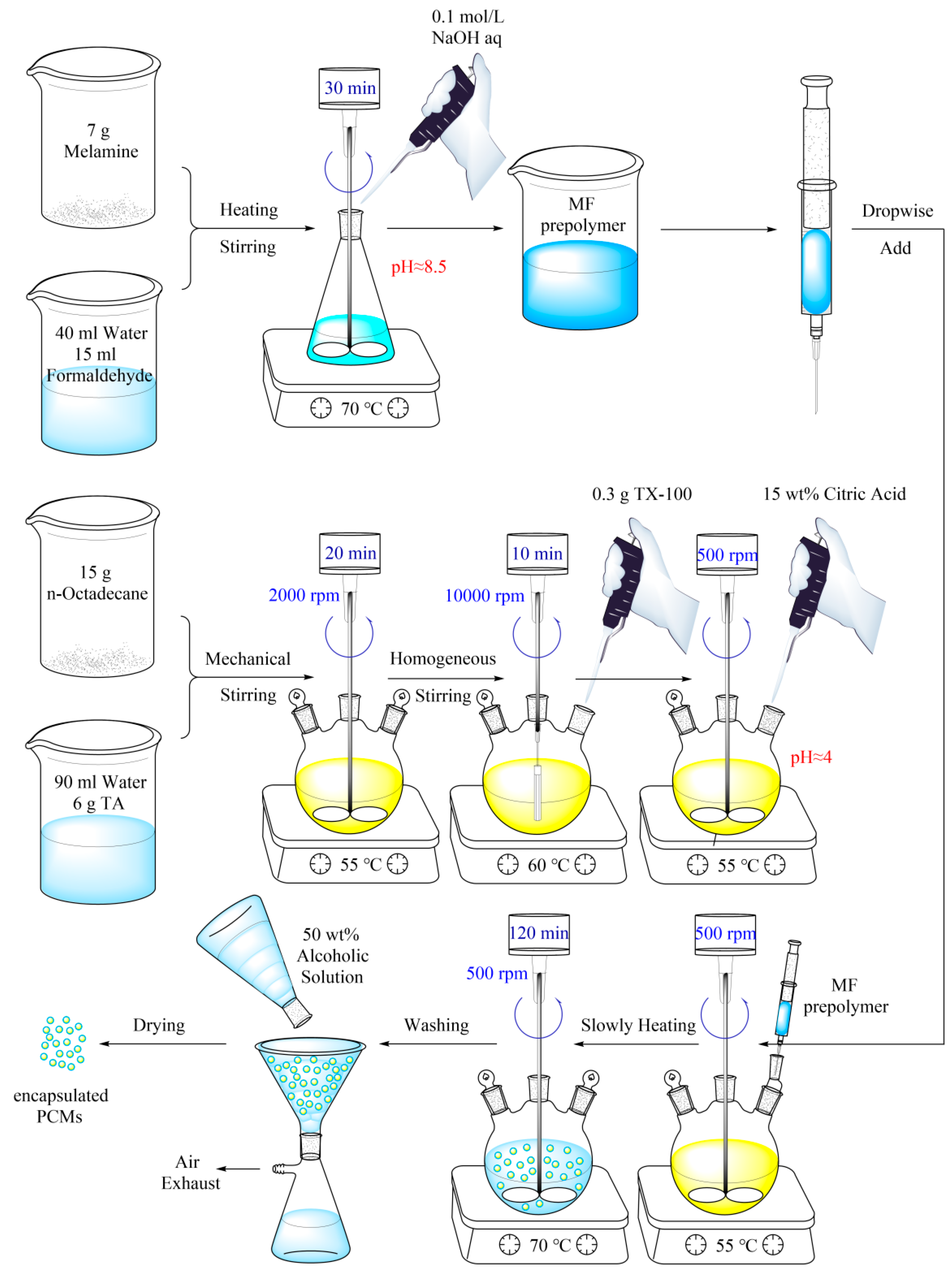
In this study, the n-octadecane@MF resin microPCMs were prepared using in situ polymerization. In this method, firstly, the emulsion of the PCMs is prepared in water, and then the prepolymer is added into the continuous phase to encapsulate the PCMs’ core within a solid shell through a polymerization reaction [42]. Figure 1 presents the basic process of preparing microPCMs by in situ polymerization.
The main ingredient of the MF prepolymer mentioned above is hydroxymethyl melamine, which is prepared from formaldehyde and melamine under alkaline conditions. The reaction principle is shown in Figure 2a. Subsequently, small prepolymer molecules are attached to the surface of the n-octadecane droplets by molecular self-assembly [24]. Finally, under acidic conditions, the small molecules of hydroxymethyl melamine dehydrate on the surfaces of the emulsion to form the MF resin and then coat the PCMs, as shown in Figure 2b.
TA was used as an emulsifier, and sodium hydroxide and citric acid were used as pH regulators in this study; the synthesis process is shown in Figure 3.
The characterization process consisted of the following steps: (1) preparation of the MF prepolymer mixture; (2) preparation of the n-octadecane core material emulsion, (3) dropping the MF prepolymer mixture into the core material emulsion to realize the coating of core material discontinuous phase droplets, and (4) washing and drying the microPCM products [43]. First, 7.0 g of melamine, 15 mL of formaldehyde solution, and 40 mL of distilled water were added into an 150 mL conical flask. A suitable amount of 0.1 mol/L sodium hydroxide solution was added to adjust the pH to approximately 8.5. Under the condition of 70 °C water bath, the magnetic stirrer was started for 30 min to receive the MF prepolymer for later use. Separately, 90 mL of distilled water and 6 g of TA were added into a 250 mL three-necked round-bottomed flask. The emulsifier was well stirred with a glass rod to dissolve the TA in distilled water and then 15 g of melted n-octadecane was added. The resulting mixture was mechanically emulsified at 55 °C at a stirring rate of 2000 rpm for 20 min. Next, 0.3 g of Triton X-100 was added to the flask, after which the emulsion was homogenized in a 60 °C water bath at a rate of 10,000 rpm for 10 min to form a stable emulsion. Finally, an appropriate amount of 15 wt.% citric acid solution was added into the stable emulsion to adjust the pH of the system to 4. In the following step, the mechanical stirring speed was set to 500 rpm. The MF prepolymer mixture was slowly added dropwise into the stable emulsion in a 55 °C water bath. After the prepolymer addition, the water bath temperature was slowly raised to 70 °C. After the microPCM emulsion was stirred at 70 °C for 2 h, the resulting microPCMs were filtered and washed with 50 wt.% ethanol solution until the pH of the filtrate was 7. The wet cake was then dried in an oven at 60 °C for 12 h to obtain the finished product.

2.3. Chemical Characterization and Morphology of microPCMs

The chemical characterization of the encapsulated microPCMs was performed using FTIR spectroscopy. The FTIR spectra of the samples were obtained using a Nicolet 6700 spectrometer (Nicolet Instrument Company, Madison, WI, USA) on a KBr sampling sheet over a range of 400 to 4000 cm−1. Figure 4a shows the FTIR spectra of n-octadecane and the as-prepared microPCMs. The position of main infrared characteristic absorption peaks corresponding to each serial number in Figure 4a are shown in Table 2. The microPCMs show five characteristic infrared peaks of pure n-octadecane (2960, 2915, 2849, 1470, and 717 cm−1) and six characteristic infrared absorption peaks of the MF resin shell material of the microPCMs (3400, 1568, 1347, 1160, 1010, and 810 cm−1). For the pure n-octadecane sample, the peaks at 2960, 2915, 2849 cm−1 are due to the C-H stretching vibration of methyl and methylene groups. The peak at 1470 cm−1 is attributed to the bending vibration of the methyl groups. The peak at 717 cm−1 in the spectrum of n-octadecane is associated with the in-plane rocking vibration of the methylene groups. For the microPCMs, the wide and large absorption peak near 3400 cm−1 is due to the superimposition of the absorption peaks of the stretching vibration of the hydroxyl and amino group residues present because of the incomplete polymerization of the hydroxymethyl melamine monomers. The peaks at 1568 cm−1 and 1347 cm−1 are assigned to the stretching vibrations of the C-N single and C-N double bonds in the aromatic rings. The peak at 1010 cm−1 is caused by the stretching vibration of alcohol carbon-oxygen single bonds, and the peak at 810 cm−1 results from the bending vibrations of the triazine rings of the MF resin. It is worth mentioning that the characteristic peak near 1160 cm−1 comes from the structure of an ether bond, which does not exist in either monomer, which strongly indicates that the MF prepolymer molecules hydroxymethyl melamine form an effective coating on the surfaces of the core material droplets.
The crystalline structures of the microPCMs were identified using X-ray diffraction (XRD). The XRD patterns of the powder samples were recorded on a Japan Rigaku D/Max 2500 X-ray spectrometer (Japan Science Corporation, Tokyo, Japan) with Cu-Kα radiation (λ = 0.154 nm) at a scanning rate of 5°/min, with 2θ ranging from 5° to 60°. The resulting XRD patterns are shown in Figure 4b. Diffraction peaks are observed at 2θ values of 7.62°, 11.46°, 15.32°, 19.20°, 19.72°, 23.30°, 24.66°, 25.62°, 34.96°, 39.64°, and 44.44° in the XRD pattern of microPCMs. These correspond to the (0 0 2), (0 0 3), (0 0 4), (0 1 0), (0 1 1), (1 0 2), (1–10), (1–12), (1 1 2), (0–22), and (1 1 7) planes of n-octadecane, respectively, according to the standard card data of JCPDS No. 53–1532. For the MF resin, because it is a large-molecule weight polymer, there are wide diffraction bands in the 2θ range of 10 to 30°, with no fine spectral peak structure, indicating that it has an amorphous structure. These characterization results suggest that the MF resin shell was successfully fabricated onto the n-octadecane core, and the encapsulation of n-octadecane did not affect its crystallization structure.
Both optical microscopy and scanning electron microscopy were used to characterize the morphology of the microPCMs. The photomicrographs were obtained by using a 52-01005 optical microscope (Bresser Optical Company, Rhede, Germany) at 40× Eyepiece magnification. The microstructure was obtained by using a FE-SEM SU8220 Series (HITACHI UHR Company, Tokyo, Japan) scanning electron microscope (SEM) with an acceleration of 20 kV. The resulting micrographs are displayed in Figure 5a,b. Figure 5a shows that all the microPCMs particles have a clearly spherical structure. Figure 5b shows that the prepared microPCMs particles exhibit regular spherical morphologies and smooth surfaces. As well, most of the sizes of the microPCMs particles are between 1~2 microns.

2.4. Thermal Properties and Thermal Stability of microPCMs

In this study, the microPCMs were used as inhibitors for exothermic reactions. For this reason, it is crucial to know the thermal properties and stabilities of the microPCMs for their application in the following semi-batch esterification reaction experiments, which can be determined through differential scanning calorimetry (DSC) analysis and thermogravimetric (TGA) analysis. The DSC analysis is used to test the phase change enthalpy of the microPCMs to obtain the encapsulation rate of the PCMs. R, which can be calculated by Equation (1), and the mass fraction of n-octadecane in microPCMs can be measured by the TGA analysis.
R = Δ H m , micro P C M s Δ H m , p u r e P C M S × 100 %
where R is the encapsulation rate of the microPCMs, ΔHm,microPCMs is the melting enthalpy of prepared microPCMs, and ΔHm,pure-PCMs is the melting enthalpy of pure n-octadecane.
The DSC analysis was performed on a TA Instruments Q20 calorimeter at a heating rate of 10 °C/min from −10 °C to 50 °C within a nitrogen atmosphere and a sample weight of approximately 5 mg. The DSC curves of n-octadecane and the microPCMs are displayed in Figure 6. The parameters related to the phase change behaviors, such as the melting (Tm) temperature and melting (ΔHm) enthalpies obtained from the DSC measurements, are listed in Table 3.
As shown in Figure 6, pure n-octadecane has a well-defined endothermic peak at approximately 28 °C for its melting peak. This result is consistent with the phase transition point of 28.18 °C of n-octadecane [44]. For the prepared microPCMs sample, the phase change behavior in the melting process is similar to that of pure n-octadecane. This demonstrated that no chemical reaction occurred between the core material (n-octadecane) and the shell material (the MF resin) [45].
In addition, it can be seen that in the DSC test results, the melting temperature of neat n-octadecane is slightly higher than that of the microPCMs, which is caused by the existence of the MF resin shell material, which delays heat diffusion into the inner core material through heat transfer [46]. Similarly, the same phenomenon can be seen in the TGA analysis test data. The encapsulation ratio represents the effective reaction heat storage and prevention of runaway exothermic reactions in the shell of the PCMs. The shell thickness of the microPCMs particles generally decreases with use, which may lead to the formation of PCMs that are easily broken after several charge cycles in the uncontrolled reaction control process [47]. Therefore, in the preparation of the microPCMs as reaction temperature inhibitors, it is necessary to maintain a balance between stability and thermal efficiency.
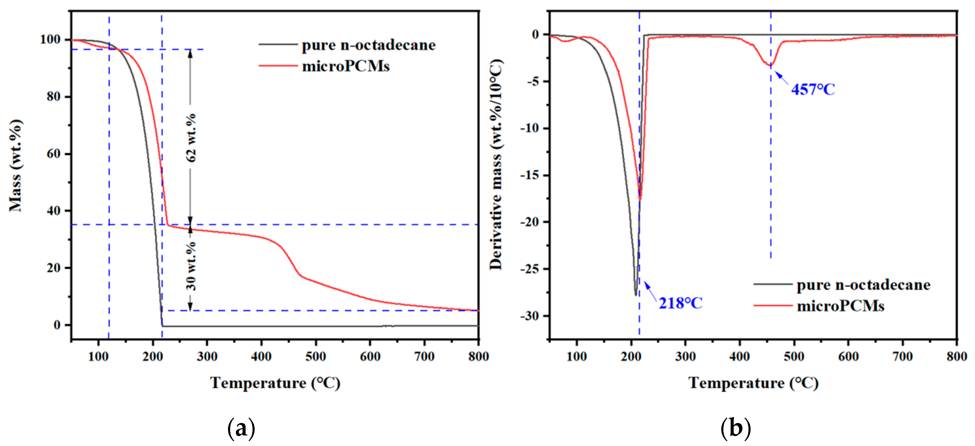
The TGA analysis was performed using a TGA/DSC 3 + thermogravimetric analyzer (Mettler Toledo Laboratory Instrument Company, Switzerland), and approximately 5 mg of the sample was heated from room temperature to 800 °C at a heating rate of 10 °C/min within a nitrogen atmosphere. The TGA analysis and derivative thermogravimetry analysis (DTG) curves are depicted in Figure 7a and Figure 7b, respectively. As well, the char yield of the samples at 800 °C are listed in Table 3. As shown in Figure 7a, pure n-octadecane exhibits a one-step weight loss within the temperature range of approximately 120 °C~220 °C, whereas the microPCMs degrade in three steps. The weight loss of approximately 3 wt.% below 120 °C is mainly due to the removal of residual water or formaldehybe solvent. The weight loss between 120 °C and 225 °C of approximately 62 wt.% is similar to that of pure n-octadecane and is mainly attributed to n-octadecane evaporation. Furthermore, the weight loss above 400 °C is due to the thermal decomposition of the MF resin. In addition, it can be seen that the volatilization rate of n-octadecane in the microPCMs is obviously slower than that of pure n-octadecane with increasing temperature. The maximum thermal weight loss rate of the core material n-octadecane is 218 °C and the corresponding maximum weight loss rate of the shell materials is 457 °C.
The TGA results confirmed that the resin shell can protect n-octadecane from leakage at 120 °C. In the actual industrial production, the reaction system temperature rarely exceeds this temperature, which demonstrates the high applicability of the microPCMs for the temperature control of the exothermic reactions.

3. Temperature Control Experiments

3.1. Reaction Scheme

Esterification reaction is a strongly exothermic reaction that is widely used in industrial production. In this study, the esterification reaction between propionic anhydride (PA) and 2-butanol (2B) were chosen as the research subject, and the equation is shown in Scheme 1.
In addition, propionic acid, which is one of the products of the main reaction, also reacts with 2B, and this equation is shown in Scheme 2.

3.2. Experimental Materials

Table 4 lists the basic information of the experimental materials used in the temperature control experiments based on esterification reactions, namely, PA, 2B, and sulfuric acid. In addition, the microPCMs previously prepared are also one of the experimental materials. All the chemicals were used without further treatment.

3.3. Experimental Procedures

3.3.1. Experimental Equipment

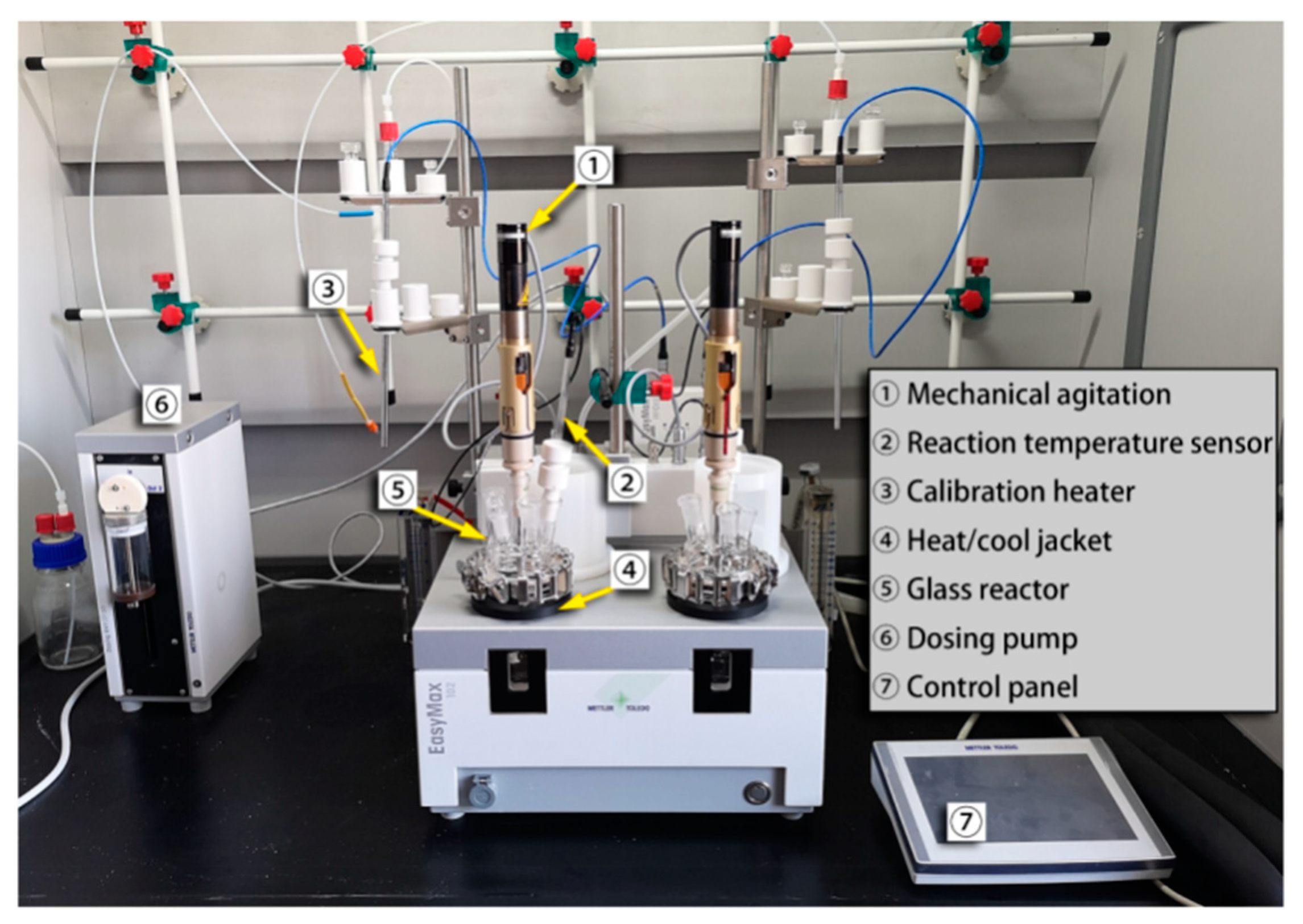
As shown in Figure 8, an EasyMax 102 calorimeter (Mettler Toledo Ltd., Zurich, Switzerland), which is an automatic synthesis reaction system with two 100 mL reactors, propeller agitators, temperature sensors, and calibrators, was chosen to carry out the esterification reaction experiments. At the same time, the temperature change in the reaction system and the exothermic situation of the reaction were also recorded. In this study, all experiments were performed in the left-hand glass reactor.
In the calorimetric process, for the medium in the reaction kettle, there exists an energy balance equation, as shown in Equation (2). The heat release rates of the reaction were determined by Equations (3)–(6).
q r = q a c + q f l o w + q d o s + q l o s s q c
where qr is the heat release rate of the reaction, qac is the heat accumulation power, qflow is the heat exchange power between the reactor and the jacket, qdos is the heat power generated by reagent dosing, and qloss is the heat loss from the reactor to the surroundings. qc is the power of the calibrator, which can calibrate the heat transfer coefficient and capacity of the reaction system. qac, qflow, qdos, and qloss can be determined from Equations (3)–(6).
q a c = m C p d T r d t
q f l o w = U S ( T r T j )
q d o s = d m d o s d t C p d o s ( T r T d o s )
q l o s s = α ( T r T a m b )
where m is the mass of the reaction material, Cp is the heat capacity of the reaction, Tr is the reactor temperature, Tj is the jacket temperature, U is the heat transfer coefficient, and S is the heat transfer area; mdos, Cpdos, and Tdos are the mass, heat capacity, and temperature of the dosed substance, respectively; α is the heat loss coefficient, and Tamb is the ambient temperature [48].
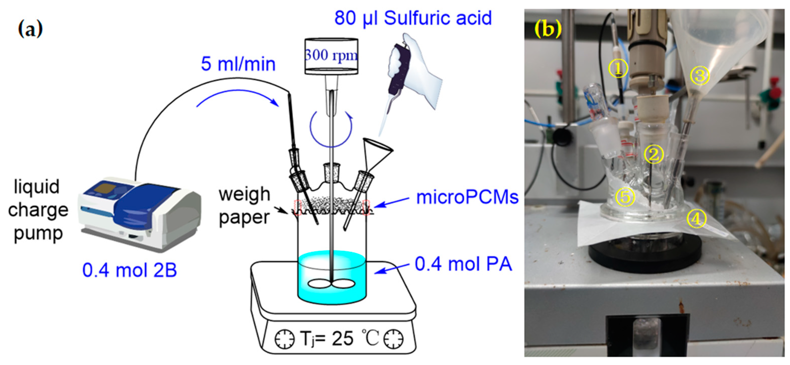
To perform the isothermal experiments, first, 0.4 mol of PA (the base material) was added into the reactor. With the Tj was set to 25 °C, 80 µL of sulfuric acid was added into the reactor at a stirring speed of 300 rpm to ensure the sulfuric acid can be scattered. When Tr was stable, 0.4 mol of 2B was added into the reactor at the rate of 5 mL/min, and the change in Tr and the exothermic rate of the reaction were simultaneously recorded. On this basis, different amounts of the microPCMs were added into the reactor at appropriate reaction temperatures in combination with the temperature rise of the reaction to explore the influence of the microPCMs on the effect of temperature control in these types of reactions. The experimental process and its facilities are shown in Figure 9a,b.
As shown in Figure 9b, component ① is the Tr sensor, used for real-time measurements of the temperature in the reactors; component ② is an injection needle, which drops 2B into the reaction system; component ③ is a long neck funnel with the function of injecting sulfuric acid to trigger the reaction; component ④ is a weighing paper that prevents the microPCMs from falling into the reactor before reaching the target temperature; and component ⑤ is the microPCMs. When the reaction system reaches the target temperature, the weighing paper is removed, and the microPCMs fall into the reactor to complete the temperature control of the reaction system.

3.3.2. Experimental Process

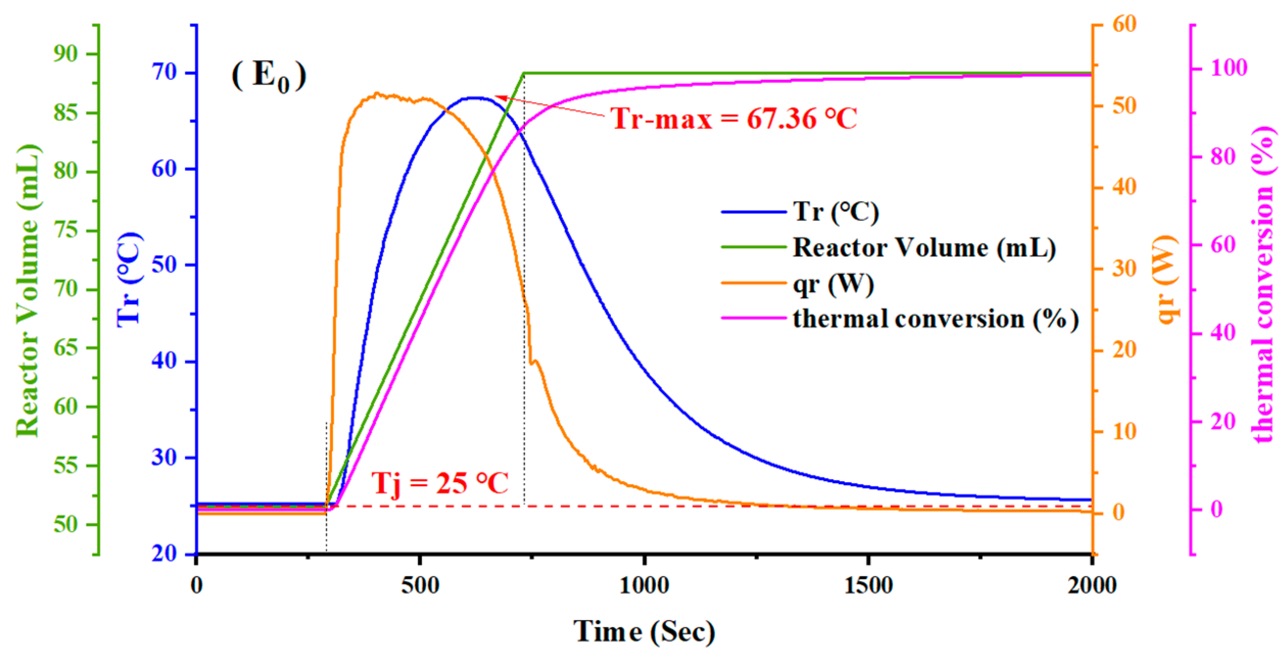
The curves of the control experiment without any microPCMs are shown in Figure 10.
The control experiment (E0) without any microPCMs added into the esterification reaction system was designed to determine the maximum temperature that the reaction system can achieve under the chosen operating conditions and to measure the real-time heat release rate during the feeding process.
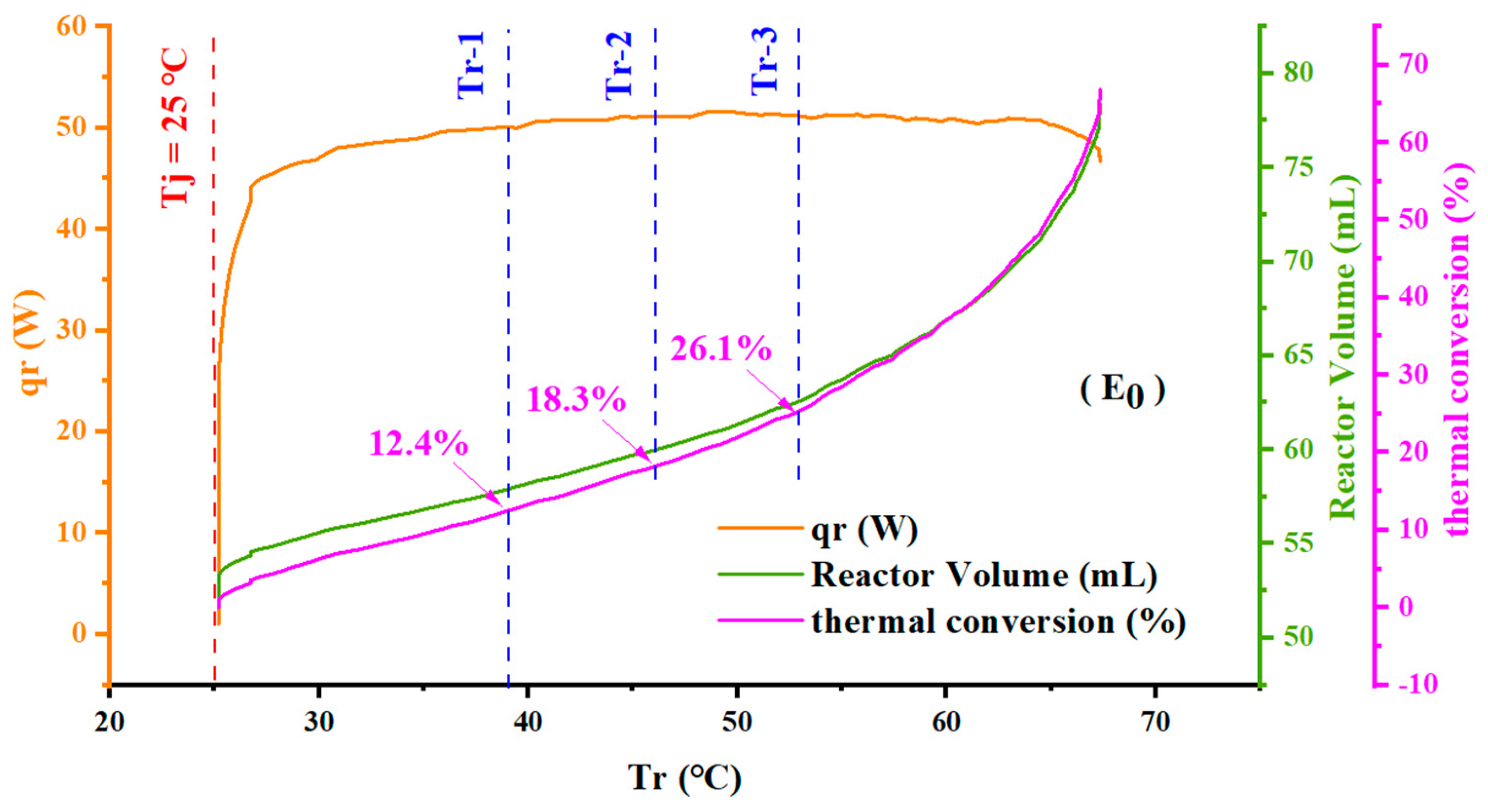
When Tr was stabilized at approximately 25 °C, the addition of 2B was initiated and the temperature in the reactor (Tr) rose rapidly, as well, the reaction heat release rate also increased rapidly. This is because for the esterification reactions, the first step of the reaction is the activation of PA. When PA is used as the base material, there are many activated structures in the system due to the early mixing of the concentrated sulfuric acid and the base material. When 2B was added, the heat release rate increased, while there was still a small release of heat after feeding, which suggests that the reaction occurs quickly but that there was a small accumulation of unreacted materials. In addition, it is noted that with the beginning of the feeding process, the heat release of the reaction begins immediately, at the same time, the reaction heat conversion increased linearly, indicating that there is almost no material accumulation at this stage, which means heat conversion can be substituted for material conversion during this stage, but with the continuous progress of the feeding process, the reaction heat release began to decline slowly after reaching a maximum value. This was due to the decrease of material concentration and catalyst concentration in the reaction system, in the reaction process, the total volume of the reaction system gradually increased, and the PA was gradually consumed, which jointly causes this phenomenon. According to Equation (6), with the gradual increase of the temperature in the reaction system, the heat dissipation qloss from the reaction system to the external environment also increased. In this process, with the continuous decrease of catalyst concentration in the system, the reaction rate began to decrease. When the reaction heat release rate was equal to the heat dissipation rate, the reaction system temperature (Tr) reached its highest temperature of 67.36 °C, and then Tr began to decrease. Compared with the initial reaction temperature of 25 °C, the temperature increased by approximately 42 °C. To explore the temperature intervention influence of the microPCMs on the temperature during the reaction processes, different amounts of the microPCMs were added at 33% (39 °C), 50% (46 °C), and 67% (53 °C) of the maximum temperature increase. The operating conditions of the temperature control experiments are shown in Table 5. To reflect the relationship among Tr, qr, and reactor volume at the temperature rise stage of the reaction system in the reaction process more intuitively, Figure 11 is drawn with Tr as the abscissa on the basis of Figure 10. As shown in Figure 11, Tr-1, Tr-2, and Tr-3 correspond to three different addition temperatures of the microPCMs.

4. Result and Discussion

4.1. Experimental Results

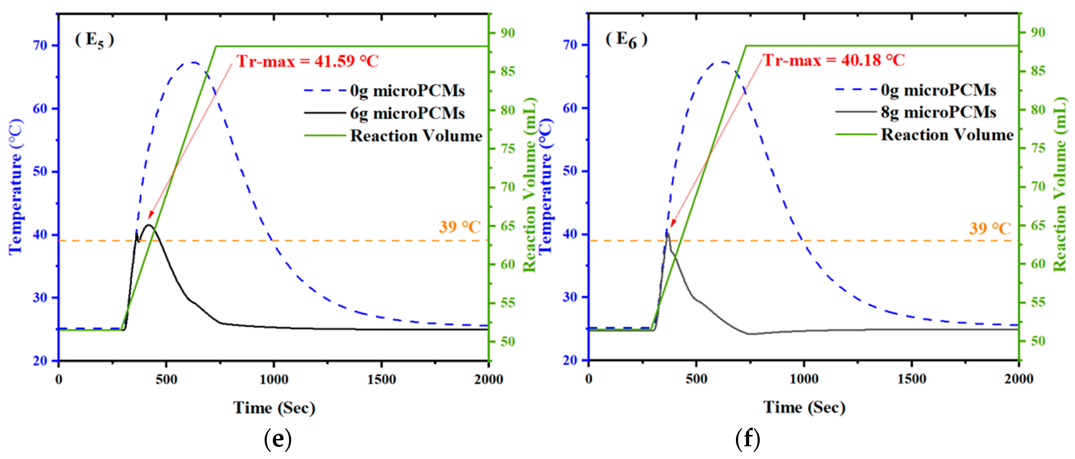
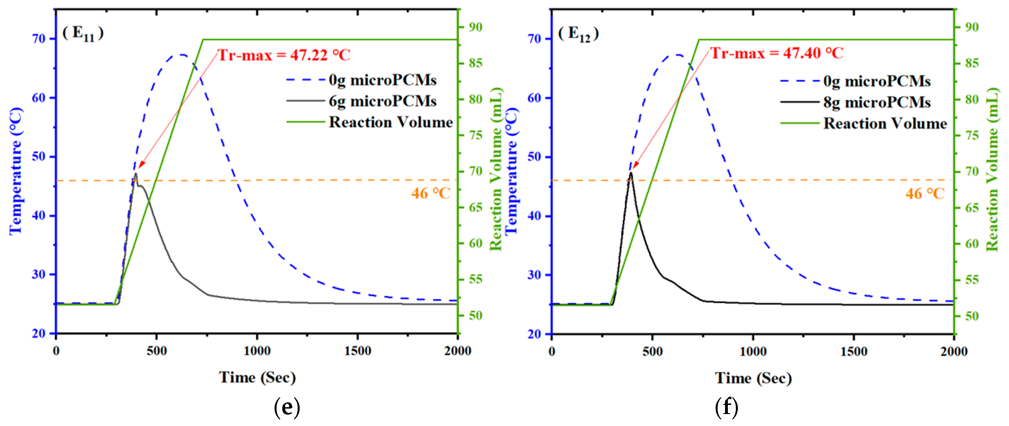
The experimental results based on the microPCMs are shown in Figure 12, Figure 13 and Figure 14.

4.2. Effect of the Amount of microPCMs on Temperature Control

In this study, to explore the influence of the amount of microPCMs on the temperature control effect, the microPCMs were first introduced to conduct temperature control experiments at 39 °C when the reaction temperature rose to one third and 46 °C, when the reaction temperature rose to a half of the maximum temperature rise. According to the experimental results of E1, E2, E3, and E4, when 2 g, 4 g, 5 g, and 5.5 g of microPCMs were added at 39 °C, the maximum reaction temperatures (Tr-max) were 62.30 °C, 56.07 °C, 51.36 °C, and 45.35 °C, which represented a decrease of 5.06 °C, 11.29 °C, 16.00 °C, and 22.01 °C, respectively. According to the experimental results of E7, E8, E9, and E10, the Tr-max were 60.96 °C, 56.84 °C, 53.66 °C, and 43.93 °C, which represented a decrease of 6.40 °C, 10.52 °C, 13.70 °C, and 23.43 °C, respectively. It can be confirmed that the higher the amount of the microPCMs, the better the temperature control effect was.
It is worth noting that with the addition of the microPCMs, the temperature of the reaction system decreased briefly and then instantly increased. This was caused by the physical heat exchange between the microPCMs, which were at room temperature (approximately 20 °C), and the reaction reagents, which were at a higher temperature.
A caveat exists in the experimental results of E5 and E6. Except for other results, the temperature rose briefly after the physical heat exchange between the microPCMs and the reaction system, and the temperature decreased directly after the addition of the microPCMs under other operating conditions. When 6 g and 8 g of the microPCMs were added, the experimental reaction temperature curves were obviously different than those with lesser amounts of the microPCMs. This was especially the case in the results of E6, with 8 g of the microPCMs added, when the reaction temperature immediately decreased without further increases.
The main reason for this phenomenon is that with the addition of the microPCMs, the catalyst content in the reaction system was affected. In the absence of a catalyst, the reaction rate between PA and 2B is very slow and almost negligible [49]. The microPCMs were used as a reaction inhibitor in this study, and the shell material was the MF resin. It contains a large number of weakly basic amine groups that can dissociate hydroxide ions into the water. In the reaction system, hydroxide ions can exchange with anions in the reaction system to adsorb the sulfuric acid molecules that were used as catalysts. Taking the primary and secondary amino groups in the MF resin as examples, the weakly alkaline anion exchange reactions are shown in Scheme 3.
At the same time, the experimental results of E14, E15, and E16 should be noticed. After the microPCMs were added to the reaction system, the reaction temperature did not decrease immediately but experienced a brief heating process. We speculate that this was because there was a small amount of hydroxyl mixed in the shell material of the microPCMs due to incomplete dehydration condensation of the hydroxymethyl melamine monomers present in the coating of the microPCMs. When the microPCMs were added into the reaction system, the residual hydroxyl groups on the surface of the microPCMs reacted with PA and propionic acid. With the increased amounts of the microPCMs, the transient temperature rise also increased gradually from 53.95 °C to 54.16 °C; this phenomenon confirms what had been previously suspected. However, with the increased amounts of the microPCMs, the reaction temperature was quickly controlled, and the residence time of the reaction system at higher temperatures was reduced, which reduced the chance of thermal runaway accidents.

4.3. Effect of the Addition Temperature of microPCMs

In order to better explore the influence of the microPCMs adding temperature to the temperature control effect, the microPCMs were added into the reaction system at 53 °C, when the feeding process was basically complete. As shown in Figure 12 and Figure 13, when the amounts of the microPCMs were 2 g, 4 g, 5 g, and 5.5 g at 39 °C, the maximum reaction temperatures were 62.30 °C, 56.07 °C, 51.36 °C, and 45.35 °C, respectively. Compared to the temperature at the time of the addition, the temperatures increased by 23.30 °C, 17.07 °C, 12.36 °C, and 6.35 °C, respectively. When the same amounts of the microPCMs were added at 46 °C, the maximum reaction temperatures were 60.96 °C, 56.84 °C, 53.66 °C, and 49.33 °C, and the temperatures increased by 14.96 °C, 10.84 °C, 7.66 °C, and 3.33 °C, respectively.
By evaluating the above data, it can be seen that while the same amounts of the microPCMs were added into the reaction systems, the temperature control effect of adding the microPCMs at 46 °C was obviously better than that at 39 °C. However, at 53 °C, even a small amount of the microPCMs can effectively control the maximum temperature of the reaction system.
There are three main reasons for this phenomenon. First, it can be seen from Figure 11. With the feeding process, the heat release rate of the reaction was maintained at a large value, indicating that the reaction was very violent, and this process was accompanied by rapid material consumption. Furthermore, for fast reactions such as an esterification reaction with less accumulation, the mass conversion rate can be expressed by the thermal conversion rate. As shown in Figure 11, when the microPCMs was added at 39 °C, 46 °C, and 53 °C, the corresponding thermal conversion rates were 12.4%, 18.3%, and 26.1%, respectively. This indicates that the process was accompanied by a rapid consumption of PA. In addition, the continuous addition of 2B also increased the total volume of the reaction system, which led to a reduction of the concentration of the reactive materials. Therefore, the reaction system at a later time is more susceptible to the influence of the microPCMs.
Subsequently, when the microPCMs at a lower temperature (below 28.18 °C, which is the melting point of n-octadecane) were put into the reaction system at a higher temperature, physical heat exchange occurred between the reaction system and the microPCMs. With a greater temperature difference between the reaction system and the microPCMs, the impact of this effect on the reaction system also increased, which increased the control effect.
Finally, as the feeding process continued, the total mass of the reaction system increased, which means that when absorbing the same amount of energy, the larger the mass of the object, the lower the temperature change, which is one of the reasons for this phenomenon.

5. Conclusions

In this study, to verify the potential of using microPCMs as reaction inhibitors, a type of microPCM consisting of n-octadecane as the core material, encapsulated with a MF resin as the shell material, was characterized by in situ polymerization based on dehydration condensation between melamine and formaldehyde. On this basis, the semi-batch esterification reaction between PA and 2B in the kettle reactors was selected as the target reaction to explore the effects of additional amounts or additional temperatures of the microPCMs on the temperature control effect of an exothermic reaction.
It was demonstrated, through the use of optical microscopy and scanning electron microscopy, that the prepared microPCMs have integrated spherical morphologies and smooth surfaces with a particle size between 1–2 microns. Furthermore, the results of FTIR and XRD showed that there was a physical coating between n-octadecane and MF resin during the preparation of microPCMs, and that the crystal structure of the core material was also intact. In terms of phase change characteristics and thermal stability, DSC curves showed that the melting enthalpy of the prepared microPCMs was 159.3 J/g and the encapsulation rate of n-octadecane was 69.2 wt.%. These properties preliminarily proved that the prepared microPCMs have great application prospects as reaction inhibitors.
The temperature control experimental results showed that the addition of microPCMs can convert the energy of the exothermic reactions into fusion latent heat, which can effectively reduce the reaction temperature to reduce the possibility of thermal runaway accidents. The specific conclusions are as follows:
(1)
The temperature control effect of microPCMs on exothermic reaction is related to the addition amount. Maximum temperature of the reaction system declined by 5.06 °C, 11.24 °C, 16.00 °C, and 22.01 °C when 2g, 4g, 5g, and 5.5g of microPCMs was added into the reactor at the temperature of 39 °C, respectively. Meanwhile, at the addition temperature of 46 °C, the maximum temperature declined by 6.40 °C, 10.52 °C, 13.70 °C, and 23.43 °C when the same amounts of microPCMs were added.
(2)
For an exothermic reaction, the temperature control effect of microPCMs becomes better with the increase of addition temperature. When 2 g, 4 g, 5 g, and 5.5 g of microPCMs was added at the temperature of 39 °C, the temperature of the reaction system continued to rise by 23.30 °C, 17.07 °C, 12.36 °C, and 6.35 °C, respectively, before it began to decline. In comparison, the temperature of the reaction system continued to rise by 14.96 °C, 10.84 °C, 7.66 °C, and 3.33 °C, respectively, while the addition temperature increased to 46 °C. At the temperature of 53 °C, even 2 g of microPCMs could effectively control the reaction temperature.
(3)
The effect mechanism of n-octadecane@MF resin microPCMs on the temperature control of a semi-batch esterification reaction system is the combination of both physical and chemical actions. The physical action is mainly reflected in the heat exchange between the microPCMs and the reaction system and the melting endothermic of the core material. The chemical reaction is caused by the anion exchange between the MF resin and anion in the reaction system, which could absorb the catalyst so as to suspend the reaction processes.

Author Contributions

Conceptualization, L.N. and J.J.; methodology, L.N. and K.Z.; experiment, C.L. and Q.C.; characterization, C.L. and L.N.; formal analysis, C.L. and L.N.; investigation, C.L. and L.N.; resources, L.N. and J.J.; data curation, C.L. and L.N.; writing—original draft preparation, C.L.; writing—review and editing, L.N. and J.J.; visualization, C.L. and Q.C.; supervision, L.N. and J.J.; project administration, L.N. and J.J.; funding acquisition, L.N. All authors have read and agreed to the published version of the manuscript.

Funding

The authors are grateful for the support given by the National Natural Science Foundation of China (No. 51904157 and No. 21436006), Jiangsu Province “333” project (BRA2020001) and Suzhou science and technology innovation project of social development (SS202153).

Institutional Review Board Statement

Not applicable.

Informed Consent Statement

Not applicable.

Data Availability Statement

The datasets used and/or analyzed during the current study are available from the corresponding author on reasonable request.

Conflicts of Interest

The authors declare no conflict of interest.

References

  1. Chen, C.C.; Wang, T.C.; Chen, L.Y.; Dai, J.H.; Shu, C.M. Loss prevention in the petrochemical and chemical-process high-tech industries in Taiwan. J. Loss Prev. Process Ind. 2010, 23, 531–538. [Google Scholar] [CrossRef]
  2. Dakkoune, A.; Hassimi, L.V.; Leveneur, S.; Lefebvre, D.; Estel, L. Risk Anysis of French Chemical Industry. Saf. Sci. 2018, 105, 77–85. [Google Scholar] [CrossRef]
  3. Jiang, J.C.; Wu, H.; Ni, L.; Zou, M.Y. CFD simulation to study batch reactor thermal runaway behaviour based on esterification reaction. Process Saf. Environ. Protect. 2018, 120, 87–96. [Google Scholar] [CrossRef]
  4. Strasser, W. CFD study of an evaporiative trickle bed reactor: Mal-distribution and thermal runaway included by feed disturbances. Chem. Eng. J. 2010, 161, 257–268. [Google Scholar] [CrossRef]
  5. Anastasov, A.I. A study of the influence of the operating parameters on the temperature of the hot spot in a fixed bed reactor. Chem. Eng. J. 2002, 86, 287–297. [Google Scholar] [CrossRef]
  6. Rudniak, L.; Machniewski, P.M.; Milewaka, A.; Molga, E. CFD modelling of stirred tank chemical reactors: Homogeneous and heterogeneous reaction systems. Chem. Eng. Sci. 2004, 59, 5233–5239. [Google Scholar] [CrossRef]
  7. Henda, R.; Machac, A.; Nilsson, B. Heat and mass transport of a in a nonlinear fixed-bed catalytic reactor: Hot spots and thermal runaway. Chem. Eng. J. 2008, 143, 195–200. [Google Scholar] [CrossRef]
  8. Anderson, R.C. Some Problems in Chemical Kinetics and Reactivity. J. Am. Chem. Soc. 1959, 81, 6344. [Google Scholar] [CrossRef]
  9. Thomas, P.H.; Bowes, P.C. Some aspects of the self-heating and ignition of solid cellulosic materials. Br. J. Appl. Phys. 1961, 12, 222. [Google Scholar] [CrossRef]
  10. Adler, J.; Enig, J.W. The critical conditions in the thermal explosion theory with reactant. Combust. Flame 1964, 8, 97–103. [Google Scholar] [CrossRef]
  11. Morbidelli, M.; Varma, A. Parametric sensitivity and runaway in chemical reactors. Sadhana 1987, 10, 133–148. [Google Scholar] [CrossRef]
  12. Morbidelli, M.; Varma, A. A generalized criterion for parametric sensitivity: Application to thermal explosion theory. Chem. Eng. Sci. 1988, 43, 91–102. [Google Scholar] [CrossRef]
  13. Vajda, S.; Rabitz, H. Parametric sensitivity and self-similarity in thermal explosion theory. Chem. Eng. Sci. 1992, 47, 1063–1078. [Google Scholar] [CrossRef]
  14. Strozzi, F.; Zaldivar, J. A general method for assessing the thermal stability of batch chemical reactors by sensitivity calculation based on Lyapunov exponents. Chem. Eng. Sci. 1994, 49, 2681–2688. [Google Scholar] [CrossRef]
  15. Strozzi, F.; Alo, S.M.A.; Zaldi’Var, J.M. A method for assessing thermal stability of batch reactors by sensitivity calculation based on Lyapunov exponents: Experimental verification. Chem. Eng. Sci. 1994, 49, 5549–5561. [Google Scholar] [CrossRef]
  16. Steensma, M.; Westerterp, K.R. Thermally safe operation of a cooled semi-batch reactor. Chem. Eng. Sci. 1994, 43, 2125–2132. [Google Scholar] [CrossRef] [Green Version]
  17. Steensma, M.; Westerterp, K.R. Thermally safe operation of a semibatch reactor for liquid-liquid reactions. Slow reactions. Ind. Eng. Chem. Res. 1990, 29, 1259–1270. [Google Scholar] [CrossRef]
  18. Steensma, M.; Westerterp, K.R. Thermally safe operation of a semibatch reactor for liquid-liquid reactions-fast reactions. Chem. Eng. Technol. 1991, 14, 367–375. [Google Scholar] [CrossRef] [Green Version]
  19. Kummer, A.; Varga, T. What do we know about reactor runaway?—A review. Process. Saf. Environ. Prot. 2021, 147, 460–476. [Google Scholar] [CrossRef]
  20. Liu, X.F.; Meng, T.Y.; Yu, J.L. Based on VSP2, safety reliability analysis and evaluation of thermal runaway reaction relief device were carried out. J. Chem. Eng. Uni. 2010, 24, 1046–1051. [Google Scholar]
  21. Watanabe, W.S.; Zhang, D.K. The effect of inherent and added inorganic matter on low-temperature oxidation reaction of coal. Fuel Process. Technol. 2001, 74, 145–160. [Google Scholar] [CrossRef]
  22. Wang, Y.W.; Duh, Y.S.; Chu, C.M. Thermal runaway hazards of tert-butyl hydroperoxide by calorimrtric studies. J. Therm. Anal. Calorim. 2009, 95, 553–557. [Google Scholar] [CrossRef]
  23. Wang, T.; Wang, S.; Luo, R.; Zhu, C.; Akiyama, T.; Zhang, Z. Microencapsulation of phase change materials with binary cores and calcium carbonate shell for thermal energy storge. Appl. Energy 2016, 171, 113–119. [Google Scholar] [CrossRef]
  24. Aftab, W.; Huang, X.; Wu, W.; Liang, Z.; Mahmood, A.; Zou, R. Nanoconfined phase change materials for thermal energy applications. Energy Environ. Sci. 2018, 11, 1392–1424. [Google Scholar] [CrossRef]
  25. Liu, C.Z.; Rao, Z.H.; Zhao, J.T.; Huo, Y.T.; Li, Y.M. Review on nanoencapsulated phase change materials: Preparation, characterization and heat transfer enhancement. Nano Energy 2015, 13, 814–826. [Google Scholar] [CrossRef]
  26. Luo, R.; Wang, S.; Wang, T.; Zhu, C.; Nomura, T.; Akiyama, T. Fabrication of paraffin@SiO2 shape-stabilized composite change material via chemical precipication method for building energy conservation. Energy Build. 2015, 108, 373–380. [Google Scholar] [CrossRef]
  27. Yuan, Y.C.; Rong, M.Z.; Zhang, M.Q. Preparation and characterization of microencapsulated polythiol. Polymer 2008, 49, 2531–2541. [Google Scholar] [CrossRef]
  28. Wei, K.; Wang, Y.; Ma, B. Effects of microencapsulated phase change materials on the performance of asphalt binders. Renew. Energy 2019, 132, 931–940. [Google Scholar] [CrossRef]
  29. Babapoor, A.; Azizi, M.; Karimi, G. Thermal management of a Li-ion battery using carbon fiber-PCM Composties. Appl. Therm. Eng. 2015, 82, 281–290. [Google Scholar] [CrossRef]
  30. Jamekhorshid, A.; Sadrameli, S.M.; Farid, M. A review of microencapsulation methods of phase change (PCMs) as a thermal energy storage (TES) medium. Renew. Sustain. Energy Rev. 2014, 31, 531–542. [Google Scholar] [CrossRef]
  31. Zhao, C.Y.; Zhang, G.H. Review on microencapsulated phase change materials (MEPCMs): Fabrication, characterization and applications. Renew. Sust. Energy Rev. 2011, 15, 3813–3832. [Google Scholar] [CrossRef]
  32. Cheng, F.; Wei, Y.; Zhang, Y.; Wang, F.; Shen, T.; Zong, C. Preparation and characterization of phase-change material nanocapsules with amphiphilic polyurethane synthesized by 3-allyloxy-1, 2-propanediol. J. Appl. Polym. Sci. 2013, 130, 1879–1889. [Google Scholar] [CrossRef]
  33. Wang, L.Y.; Tsai, P.S.; Yang, Y.M. Preparation of silica microspheres encapsulateing phase-change material by sol-gel method in O/W emulsion. J. Microencapsule 2006, 23, 3–14. [Google Scholar] [CrossRef]
  34. Cao, F.; Yang, B. Supercooling suppression of microencapsulated phase change materials by optimizing shell composition and structure. Appl. Energy 2014, 113, 1512–1518. [Google Scholar] [CrossRef]
  35. Sharama, A.; Tyagi, V.V.; Chen, C.R.; Buddhi, D. Review on thermal energy storage with phase change materials and applications. Renew. Sustain. Energy Rev. 2009, 13, 318–345. [Google Scholar] [CrossRef]
  36. Saeid, G.M.; Ali, M.; Omid, M.; Behshad, S.M.; Hassan, J.M.; Mohammad, Z.; Hossein, A.M. A review on the applicatioins of micro-/nano-encapsulated phase change material slurry in heat transfer and thermal storage systems. J. Therm. Anal. Calorim. 2021, 145, 245–268. [Google Scholar]
  37. Zhang, M.H.; Hong, Y.; Ding, S.J.; Hu, J.J.; Fan, Y.X.; Voevodin, A.A.; Su, M. Encapsulated Nano-Heat-Sinks for Thermal Management of Heterogeneous Chemical Reactions. Nanoscale 2010, 2, 2790. [Google Scholar] [CrossRef]
  38. Odunsi, A.O.; O’donovan, T.S.; Reay, D.A. Temperature Stabilisation in Fischer-Tropsch Reactors Using Phase Change Material (PCM). Appl. Therm. Eng. 2016, 93, 1377–1393. [Google Scholar] [CrossRef] [Green Version]
  39. Odunsi, A.O.; O’donovan, T.S.; Reay, D.A. Dynamic Modeling of Fixed-Bed Fischer-Tropsch Reactors with Phase Change Material Diluents. Chem. Eng. Technol. 2016, 39, 2066–2076. [Google Scholar] [CrossRef]
  40. Li, K.Z.; Cheng, X.M.; Li, N.N.; Zhu, X.; Wei, Y.G.; Zhai, K.; Wang, H. A Yolk/Shell Strategy for Designing Hybrid Phase Change Materials for Heat Management in Catalytic Reactions. J. Chem. Mater. Chem. A 2017, 5, 24232–24246. [Google Scholar] [CrossRef]
  41. Chen, Q.; Ni, L.; Jiang, J.C.; Parker, T.; Chen, Z.Q.; Cheng, Z.; Jiang, W.; Wang, Q.S. Inhibition of exothermic runaway of batch reactors for the homogeneous esterification using nano-encapsulated phase change materials. Appl. Therm. Eng. 2020, 178, 115531. [Google Scholar] [CrossRef]
  42. Moreno, P.; Miro, L.; Sole, A.; Barreneche, C.; Sole, C.; Martorell, L.; Cabeza, L.F. Corrosion of metal and metal alloy containers in contact with phase change materials (PCM) for potential heating and cooling applications. Appl. Energy 2014, 125, 238–245. [Google Scholar] [CrossRef]
  43. Salunkhe, P.B.; Shembekar, P.S. A review on effect of phase change material encapsulation on the thermal performance of a system. Renew. Sust. Energ. Rev. 2012, 16, 5603–5616. [Google Scholar] [CrossRef]
  44. Liang, S.; Li, Q.; Zhu, Y.; Chen, K.; Tian, C.; Wang, J.; Bai, R. Nanoencapsulation of n-octadecane phase change material with silica shell through interfacial hydrolysis and polycondensation in miniemulsion. Energy 2015, 93, 1684–1692. [Google Scholar] [CrossRef]
  45. Su, W.; Darkwa, J.; Kokogiannakis, G. Review of solid-liquid phase change materials and their encapsulation technologies. Renew. Sustain. Energy Rev. 2015, 48, 373–391. [Google Scholar] [CrossRef]
  46. Zhang, H.; Wang, X.; Wu, D. Silica encapsulation of n-octadecane via sol–gel process: A novel microencapsulated phase-change material with enhanced thermal conductivity and performance. J. Colloid Interface Sci. 2010, 343, 246–255. [Google Scholar] [CrossRef]
  47. Fan, Z.G.; Han, P.J.; Zhang, Z.G.; Hu, Z.J. Optimized emulsifier combination based microencapsulated phase change materials (MicroPCMs): Preparation, characterization, and applications. Renew. Sustain. Energy Rev. 2020, 12, 014102.1–014102.7. [Google Scholar] [CrossRef]
  48. Cheng, Z.; Ni, L.; Wang, J.J.; Jiang, J.C.; Yao, H.; Chen, Q.; Cui, F.S.; Jiang, W.; Ye, S.L. Process hazard evaluation and exothermic mechanism for the synthesis of n-butylmagnesium bromide Grinard reagent in different solvents. Process Saf. Environ. Prot. 2021, 147, 654–673. [Google Scholar] [CrossRef]
  49. Dhanuka, V.R.; Malshe, V.C.; Chandalia, S.B. Kinetics of the liquid phase esterification of carb-Xylic acids with alcohols in the presence of acid catalysts: Re-interpretation of published data. Chem. Eng. Sci. 1977, 32, 551–556. [Google Scholar] [CrossRef]
Figure 1. Basic process of in situ polymerization.
Processes 10 00239 g001
Figure 2. (a) Formation of MF prepolymer and (b) formation of MF resin.
Processes 10 00239 g002
Figure 3. Fabrication schematic diagram of encapsulated n-octadecane with the MF resin shell.
Processes 10 00239 g003
Figure 4. (a) FTIR spectra and (b) XRD patterns of n-octadecane and microPCMs.
Processes 10 00239 g004
Figure 5. (a) Optical micrographs of the microPCMs, (b) SEM micrographs of the microPCMs.
Processes 10 00239 g005aProcesses 10 00239 g005b
Figure 6. DSC curves of pure n-octadecane and the microPCMs.
Processes 10 00239 g006
Figure 7. (a) TGA and (b) DTG data curves of n-octadecane and the microPCMs.
Processes 10 00239 g007
Scheme 1. The main reaction scheme of the esterification reaction between PA and 2B.
Processes 10 00239 sch001
Scheme 2. The side reaction scheme of the esterification reaction between PA and 2B.
Processes 10 00239 sch002
Figure 8. The instruments used in the temperature control experiments (EasyMax 102).
Processes 10 00239 g008
Figure 9. (a) Experimental process and (b) experimental equipment for temperature control experiments using the microPCMs.
Processes 10 00239 g009
Figure 10. Experimental results of the control experiment without the microPCMs.
Processes 10 00239 g010
Figure 11. Experimental results of the control experiment E0 (Tr as the abscissa).
Processes 10 00239 g011
Figure 12. Experimental results with addition amount of (a) 2 g, (b) 4 g, (c) 5 g, (d) 5.5 g, (e) 6 g, (f) 8 g microPCMs at the temperature of 39 °C.
Processes 10 00239 g012aProcesses 10 00239 g012b
Figure 13. Experimental results with addition amount of (a) 2 g, (b) 4 g, (c) 5 g, (d) 5.5 g, (e) 6 g, (f) 8 g microPCMs at the temperature of 46 °C.
Processes 10 00239 g013aProcesses 10 00239 g013b
Figure 14. Experimental results with addition amount of (a) 2 g, (b) 4 g, (c) 6 g, (d) 8 g microPCMs at the temperature of 53 °C.
Processes 10 00239 g014
Scheme 3. The weakly alkaline anion exchange reactions in the reaction system.
Processes 10 00239 sch003
Table 1. Experimental materials used in the preparation of microPCMs.
Experimental MaterialsCAS No.Molecular FormulaWeight (wt.%)Source
n-octadecane593-45-3C18H38≥99.0 wt.%Aladdin Reagent (Shanghai, China)
Melamine1058-78-1C3H6N6≥99.0 wt.%Aladdin Reagent (Shanghai, China)
Ethanol64-47-5C2H6O≥99.7 wt.%Ya Sheng Chemical (Wuxi, China)
Formaldehyde solution50-00-0CH2O36 wt.%~38wt.%Xi Long Scientific (Shantou, China)
TA------≈19 wt.%Rui Gong Chemical Reagent
(Shanghai, China)
Triton X-1009002-93-1C34H62O11≥95.0 wt.%Sinopharm Chemical Reagent
(Shanghai, China)
Sodium hydroxide1310-73-2NaOH≥99.0 wt.%Sinopharm Chemical Reagent
(Shanghai, China)
Anhydrous Citric acid77-92-9C6H8O7≥99.5 wt.%Sinopharm Chemical Reagent
(Shanghai, China)
Distilled water7732-18-5H2O---Wan Qing Glass & Instrument
(Nanjing, China)
Table 2. Main infrared absorption characteristic peaks of microPCMs and n-octadecane.
Sequence Number
Peak position (cm−1)717147028492915296081010101160134715683400
Table 3. Thermal properties of the microPCMs with the MF resin shell.
SampleTm (°C)ΔHm (J/g)Encapsulation Ratio (%)Char Yield at 800 °C
n-octadecane27.28230.2---0.19%
microPCMs27.47159.369.24.88%
Table 4. Experimental materials used in the temperature control experiments.
Experimental MaterialsCAS No.Molecular FormulaWeight (wt.%)Source
Propionic anhydride123-62-6C6H10O3≥97.0 wt.%Aladdin Reagent (Shanghai, China)
2-Butanol78-92-2C4H10O≥95.0 wt.%Sinopharm Chemical Reagent
(Shanghai, China)
Sulfuric acid7664-93-9H2SO4≥98.0 wt.%Ling Feng Chemical Reagent
(Shanghai, China)
microPCMs---------Laboratory made
Table 5. Operating conditions of the temperature control experiments using the microPCMs.
TestAddition Temperature (°C)Addition Amounts (g)Maximum Temperature of Reactor (°C)
E0---067.36
E139262.30
E239456.07
E339551.36
E4395.545.35
E539641.59
E639840.18
E746260.96
E846456.84
E946553.66
E10465.549.33
E1146647.22
E1246847.40
E1353253.51
E1453453.95
E1553654.03
E1653854.16
Publisher’s Note: MDPI stays neutral with regard to jurisdictional claims in published maps and institutional affiliations.