Article

The Design and Magnetic Field Analysis of a Double Rotor Permanent Magnet Braking Device

1
School of Automotive and Traffic Engineering, Jiangsu University, Zhenjiang 212013, China
2
School of Automotive and Traffic Engineering, Jiangsu University of Technology, Changzhou 213001, China
*
Author to whom correspondence should be addressed.
Processes 2022, 10(2), 346; https://doi.org/10.3390/pr10020346
Submission received: 17 December 2021 / Revised: 24 January 2022 / Accepted: 27 January 2022 / Published: 11 February 2022

Abstract

:
During long-term continuous braking, high-intensity braking, or frequent braking, the temperature of the brake disc or brake drum will increase significantly, resulting in a decrease in the friction coefficient, the aggravation of the wear degree, and the dangerous heat recession of partial or even total loss of braking efficiency. This paper focuses on an innovative double rotor permanent magnet braking device, which is located on the inner side of the wheel hub, to improve the heat decay resistance of the friction braking device. The structure and principle of the double rotor permanent magnet braking device were given, and its main structural parameters were designed, calculated, and optimized. The geometric model and finite element model of the double rotor permanent magnet braking device were established. The static and transient magnetic field analysis and the braking torque characteristic analysis of the double rotor permanent magnet braking device were carried out by using Maxwell electromagnetic analysis software. The results show that the magnetic flux density in the working area of the double rotor permanent magnet braking device increases with the increase in rotation speed, the braking torque changes with the change of rotation speed, and the maximum braking torque occurs in the low-speed area, which is consistent with the theoretical calculation results. This provides a theoretical basis for the follow-up prototype test of the double rotor permanent magnet braking device.

1. Introduction

The braking system is one of the important components of the vehicle chassis and is directly related to the comprehensive performance of the vehicle and its safety. During long-term continuous braking, high-intensity braking, or frequent braking, the temperature of the brake disc or brake drum will increase significantly, resulting in the decrease in the friction coefficient, the aggravation of the wear degree, and the dangerous heat recession of partial or even total loss of braking efficiency. Although the application of an anti-lock braking system (ABS) and electronic brake-force distribution system (EBD) improves the stability and reliability of vehicle braking, they have little effect on the heat decay of friction brakes. At present, many countries, including China, have clearly stipulated that vehicles, which meet certain specifications or above, must be equipped with auxiliary braking devices to effectively divert the load of friction brakes and improve vehicle braking safety. A permanent magnet braking device is one of the auxiliary braking devices, which has the advantages of non-contact, small volume, light weight, low magnet temperature rise, energy-saving, and environmental protection. However, at present, the permanent magnet braking device is generally installed behind the transmission or in front of the main reducer. There are some problems, such as only acting on the driving wheels, the braking torque of the driving wheels on both sides cannot be adjusted independently, the assembly needs space and is relatively difficult, it is not suitable for high-quality integrated control with friction braking devices, etc.
The dual rotor permanent magnet braking device integrates the dual rotor permanent magnet braking assembly with the vehicle hub and can be used for each wheel. It has the advantages of compact structure, convenient layout, easily integrated control, good heat decay resistance, etc. At present, there is relatively little research on the dual rotor permanent magnet braking device integrated with the vehicle hub at home and abroad. Ref. [1] gave a brake combined with permanent magnet braking and friction braking and analyzed its performance. However, the integrated brake can provide a small permanent magnet braking torque, and the friction braking and permanent magnet braking acted on the same brake disc, which made little improvement in heat fading resistance. Ref. [2] proposed a permanent magnet and friction-integrated braking device, which was located on the inside of the hub. Because the permanent magnet braking device was located inside the integrated brake disc, the force radius of the permanent magnet braking action was small, the auxiliary braking torque generated needed to be improved, and the permanent magnet braking torque adjustment device was more complex. In addition, the above two were based on the integration of a friction braking device and a permanent magnet braking device and did not involve the integration of a permanent magnet braking device and the vehicle hub.
In view of the above, this paper explores an innovative double rotor permanent magnet braking device, which is located on the inner side of the wheel hub, to improve the heat decay resistance of the friction braking device. The following contents are arranged as follows. In Section 2, the structure and working principle of the new double rotor permanent magnet braking device are given. In Section 3, the parameters of the double rotor permanent magnet braking device are calculated and optimized. In Section 4, the magnetic fields of the double rotor permanent magnet braking device are analyzed based on Maxwell electrical analysis software. In Section 5, the full text is summarized.

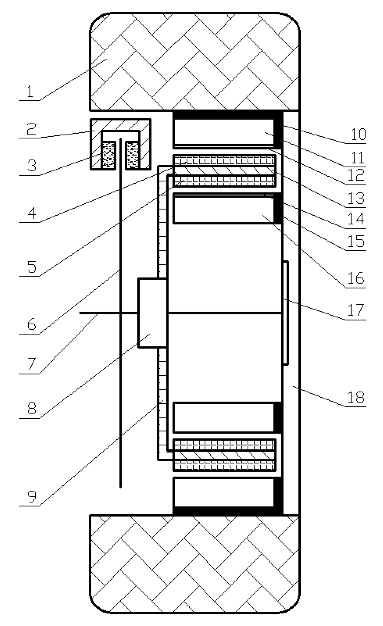
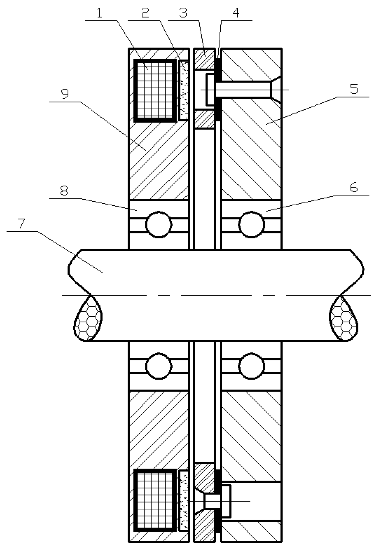
2. Structure and Principle of Double Rotor Permanent Magnet Braking Device

The structure of the proposed double rotor permanent magnet braking device is shown in Figure 1. The braking device has two relatively independent braking systems: a friction braking device and a permanent magnet braking device. When the braking device works, the friction braking device and the permanent magnet braking device can be controlled centrally without interference with each other, so as to give full play to the advantages of the two braking modes [3,4,5]. The friction braking device is mainly composed of friction blocks, the brake disc, and the brake caliper body. During friction braking, the relative movement of the two friction pads presses against the brake disc, so as to reduce the speed of the brake disc due to the action of friction. Because the brake disc is fixed on the half shaft, the speed of the half shaft is reduced and the friction braking is completed. The permanent magnet braking device consists of an electromagnetic clutch, a bracket, a rotor drum, some permanent magnets, etc. The structure of the electromagnetic clutch is shown in Figure 2. When the permanent magnet braking device does not work, the electromagnetic clutch does not work and is in a disengaged state. When the permanent magnet braking device works, the electromagnetic clutch works and is in the combined state. At this time, the driven plate of the clutch is fixed so that the bracket and the permanent magnets in the bracket do not rotate and the rotor drum and its copper coating rotate with the rotation of the hub. The copper coatings cut the magnetic field of the permanent magnets, resulting in the braking torque and the deceleration of the hub [6,7,8].
When the vehicle is braked at a low speed, because the wheel speed is relatively slow and the braking intensity is relatively low, the braking requirements can be completed only by friction braking. At this time, the electromagnetic clutch does not work, so the driving disc of the electromagnetic clutch does not make contact with the driven disc, the bracket rotates freely, and the permanent magnets rotate freely with the bracket. The permanent magnet braking device does not generate an eddy current (that is, no braking torque), and the braking torque is provided by the friction braking device. When the vehicle is braked at a high speed and the required braking strength is relatively large, the electromagnetic coil in the driving plate of the electromagnetic clutch is passed by the current, which generates a magnetic force to attract the armature to overcome the elastic force of the leaf spring and press the friction plate in the driving plate of the electromagnetic clutch. At this time, the driven plate of the electromagnetic clutch is fixedly connected with the driving plate of the electromagnetic clutch through electromagnetic force. The bracket fixed with the driven plate of the electromagnetic clutch is also fixed. The inner and outer rotor drums of the permanent magnet braking device, which are driven by the hub, rotate. The copper coatings on the inner and outer rotor drums cut the magnetic field line of the permanent magnets, and the permanent magnet braking torque is generated due to the eddy current effect, which reduces the speed of the inner and outer rotor drums. Thus, the rotating speed of the hub fixedly connected with the inner and outer rotor drums is also reduced, and, finally, the vehicle speed is reduced. It indirectly reduces the higher braking strength required by the friction brake, reduces the loss of friction parts, and improves the heat attenuation resistance of the friction braking device.

3. Parameter Design of Double Rotor Permanent Magnet Braking Device

3.1. Braking Torque Model of Permanent Magnet Braking Device

In this paper, a vehicle model was selected as the research object, and some vehicle parameters of the selected model are shown in Table 1.
The air gap flux density B under the combined action of a permanent magnet magnetic field and an eddy current magnetic field in a permanent magnet braking device can be obtained according to the equivalent magnetic circuit method, which can be expressed as follows [9,10]:
B = 2 μ 0 H c h 3 l g + K d μ 0 σ ω n w r j Δ h
where μ0 is the vacuum permeability, μ0 = 4π × 10−7 H/m; Hc is the coercivity of the permanent magnet, A/m; h is the radial height of permanent magnet, m; lg is the clearance between the permanent magnet and the rotor drum, m; Kd is the conversion coefficient of eddy current, generally taken as 0.6~1.2; σ is the conductivity of rotor drum, S/m; ωnis the angular velocity of rotor drum, rad/s; w is the circumferential width of the permanent magnet, m; rj is the inner diameter of the rotor drum, m; ∆h is the average equivalent penetration of the eddy current in the rotor drum, ∆h = (2/σμω)1/2. In which, μ is the permeability of the rotor drum, H/m; μ = μ0μr, and μr is the relative permeability; ω is the angular frequency of magnetic field variation, ω = 2πNpn/60, and Np is the number of pole pairs, n is the speed of rotor drum, r/min.
The magnetic flux density can be expressed as [11]:
J = σ ω n r j B N p + ( 2 π r / l w ) 2 / N p
According to the existing literature, it can be determined that the electric power consumed in the rotor drum may be expressed as [12]:
P = π σ a r j 3 B 2 ω n 2 2 Δ
where a is the axial length of the permanent magnet, m.
Meanwhile, the braking torque Ty of the permanent magnet braking device can be expressed as:
T y = P ω n
When the permeability and conductivity of the rotor drum are constant, the braking torque of the permanent magnet braking device can be obtained by substituting Equation (1) and Equation (2) into Equation (3):
T y = π σ a r j 3 Δ h ω n 2 ( 2 μ 0 H c h 3 l g + K d μ 0 σ ω n w r j Δ h ) 2
The torque of double rotor permanent magnet braking device is the sum of braking torque generated by internal and external permanent magnet braking devices, which can be expressed as:
T y = T o u t + T i n = π σ a 1 r j 1 3 Δ h ω n 2 ( 2 μ 0 H c h 1 3 l g + K d μ 0 σ ω n w 1 r j 1 Δ h ) 2 + π σ a 2 r j 2 3 Δ h ω n 2 ( 2 μ 0 H c h 2 3 l g + K d μ 0 σ ω n w 2 r j 2 Δ h ) 2
where Tout and Tin are the braking torque of internal and external permanent magnet braking devices, respectively; a1, w1, and h1 are the axial length, circumferential width, and radial height of the outer permanent magnet of the double rotor permanent magnet braking device, respectively, m; a2, w2, and h2 are the axial length, circumferential width, and radial height of the inner permanent magnet of the double rotor permanent magnet braking device, respectively, m.

3.2. Parameter Calculation of Permanent Magnet Braking Device

(1) Rotor Drum
The tire specification of the selected vehicle model is 9.00-20-18PR, and the diameter of the wheel rim is 508 mm. According to the assembly requirements, a certain heat dissipation gap should be reserved between the rotor drum outside the permanent magnet braking device and the wheel rim. In this paper, according to the brake technical manual, the diameter of the outer rotor drum is taken as 80% of the diameter of the wheel rim, then the radius rj1 of the outer rotor drum should be less than or equal to 203 mm.
The dimensional parameters of the rotor drum can be determined according to the heat capacity of the solid part of the rotor drum. Assuming that the rotor drum is in an adiabatic state during braking, the heat capacity of the rotor drum will meet the following requirements [13]:
{ m d C d δ 1 m g v 2 25.92 g m d = ρ π ( r w 1 2 r j 1 2 ) l w
where md is the mass of solid part of rotor drum, kg; Cd is the specific heat capacity of the rotor drum, J/(kg·K); δ1 is the allowable temperature rise of rotor drum, K; ρ is the density of rotor drum, kg/m3; lw is the width of rotor drum, m; rw1 is the outer radius of outer rotor drum, m; rj1 is the inner radius of outer rotor drum, m.
According to Equation (5), the inner radius rj1 of the outer rotor drum is 193 mm and the width lw of the rotor drum is 60 mm.
(2) Air gap
The air gap lg of the permanent magnet braking device refers to the air gap between the permanent magnets and the rotor drum. It is an important design parameter affecting the braking performance of the permanent magnet braking device, and the influence of many factors should be considered in the design.
According to the structural parameters of the permanent magnet braking device given in reference [14], the relationship curves between air gap lg, magnetic flux density B, and braking torque Ty can be fitted according to Equations (2) and (4), as shown in Figure 3.
It can be seen from Figure 3 that with the increase in the air gap lg, the magnetic flux density B and braking torque Ty decrease. Therefore, it is hoped that the air gap lg should be as small as possible in the design. However, considering the influence of the assembly tolerance, machining accuracy, and thermal deformation of the rotor drum of the permanent magnet braking device, the air gap lg is selected as 1 mm.
(3) Copper-clad layer
In order to enhance the conduction of the rotor drum eddy current, the surface treatment technology of copper coating is usually adopted on the working surfaces of the rotor drum. The local schematic diagram of a permanent magnet braking device plated with a copper coating is shown in Figure 4.
After the rotor drum is plated with a copper coating, the power P consumed is:
P = P h + P c u
where Ph is the power consumed by the non-copper clad part of rotor drum, W and Pcu is the power consumed by the copper coating on rotor drum, W.
When the permanent magnet braking device works, the eddy current on the rotor drum is mainly concentrated on the copper clad layer, and the power Pcu consumed on the copper clad layer can be expressed as [15]:
P c u = σ c u μ 0 2 ( H c h ) 2 ( h + l g + δ ) 2 ( S 1 δ )
where σcu is the conductivity of pure copper, S/m; S1 is the area of eddy current, m2; and δ is the thickness of the copper-clad layer, m.
It can be seen from Equations (8) and (9) that the thickness of the copper coating has a certain impact on the braking torque of the permanent magnet braking device. According to the structural parameters of the permanent magnet braking device given in reference [14], the relationship curves between the braking torque of the permanent magnet braking device and the speed of the rotor drum under different copper coating thicknesses can be fitted, as shown in Figure 5. In the figure, the three curves represent the relationship curves between the speed of the rotor drum and the braking torque of the permanent magnet braking device when the thickness of the copper-clad layer is 0 mm, 0.5 mm, and 1 mm, respectively.
It can be seen from Figure 5 that the greater the thickness of the copper coating, the greater the maximum braking torque; with the increase in rotor drum speed, the greater the thickness of the copper coating, the faster the braking torque decreases; and the greater the thickness of the copper coating, the easier it is to obtain a larger braking torque in the low-speed region. According to the relationship curves shown above and the limitation of installation space, the thickness of the copper coating on the working surfaces of the inner and outer rotor drum is taken as 1 mm.
(4) Permanent magnet
The structural parameters of a permanent magnet mainly include axial length a, circumferential width w, and radial height h.
I. Axial length a
The axial length of the permanent magnet should generally be less than or equal to the axial length of the rotor drum. Meanwhile, in order to facilitate the installation of the rear end cover of the rotor drum, the axial length of the rotor drum is usually 1.35~1.45 times of the axial length of the permanent magnet, which is taken as 1.4 times here. Therefore, the axial length of the permanent magnet is:
a = l 1.4
II. Circumferential width w
The permanent magnet is generally made of Nd-Fe-B material. The Nd-Fe-B material is brittle and cannot be directly fixed by machining bolt holes on it. Therefore, it is usually installed by embedding the magnet cage. The spacing width between the permanent magnets of the magnet cage is generally at least 0.3w, so the circumferential width of the permanent magnet can be expressed as:
π ( r j l g ) N p + 1 1.3 w π ( r j l g ) N p
III. Radial height h
During the working period of the permanent magnet braking device, it is expected that the permanent magnet can be at the best working point, and the best working point depends on the length of the magnetization direction of the permanent magnet to a certain extent. Because the permanent magnet in this paper adopts radial magnetization, the length of the magnetization direction is the radial height h of the permanent magnet. When determining the radial height of the permanent magnet, the following two factors should be considered: firstly, if the radial height is too small, the demagnetization of the permanent magnet is easy to occur, so the radial height cannot be too small; secondly, because the magnetic resistance in the magnetization direction of the permanent magnet is large, the radial height cannot be too large. At the same time, the radial height of the permanent magnet is also constrained by the assembly sizes of the flange inside the rotor drum. Therefore, considering the above factors and the installation space inside the rotor drum, the radial height range of the permanent magnet is determined as 8 mm ≤ h ≤ 20 mm.

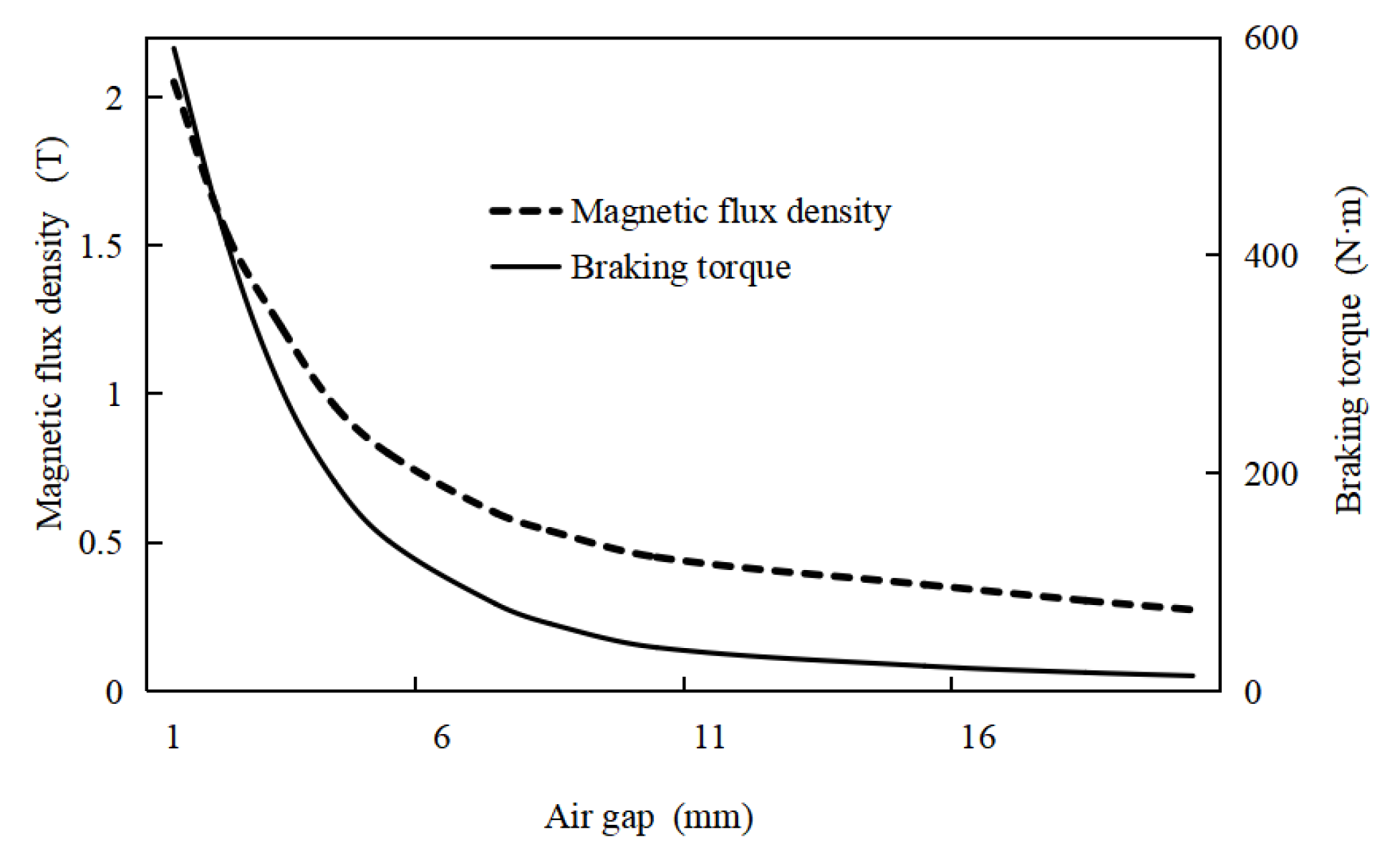
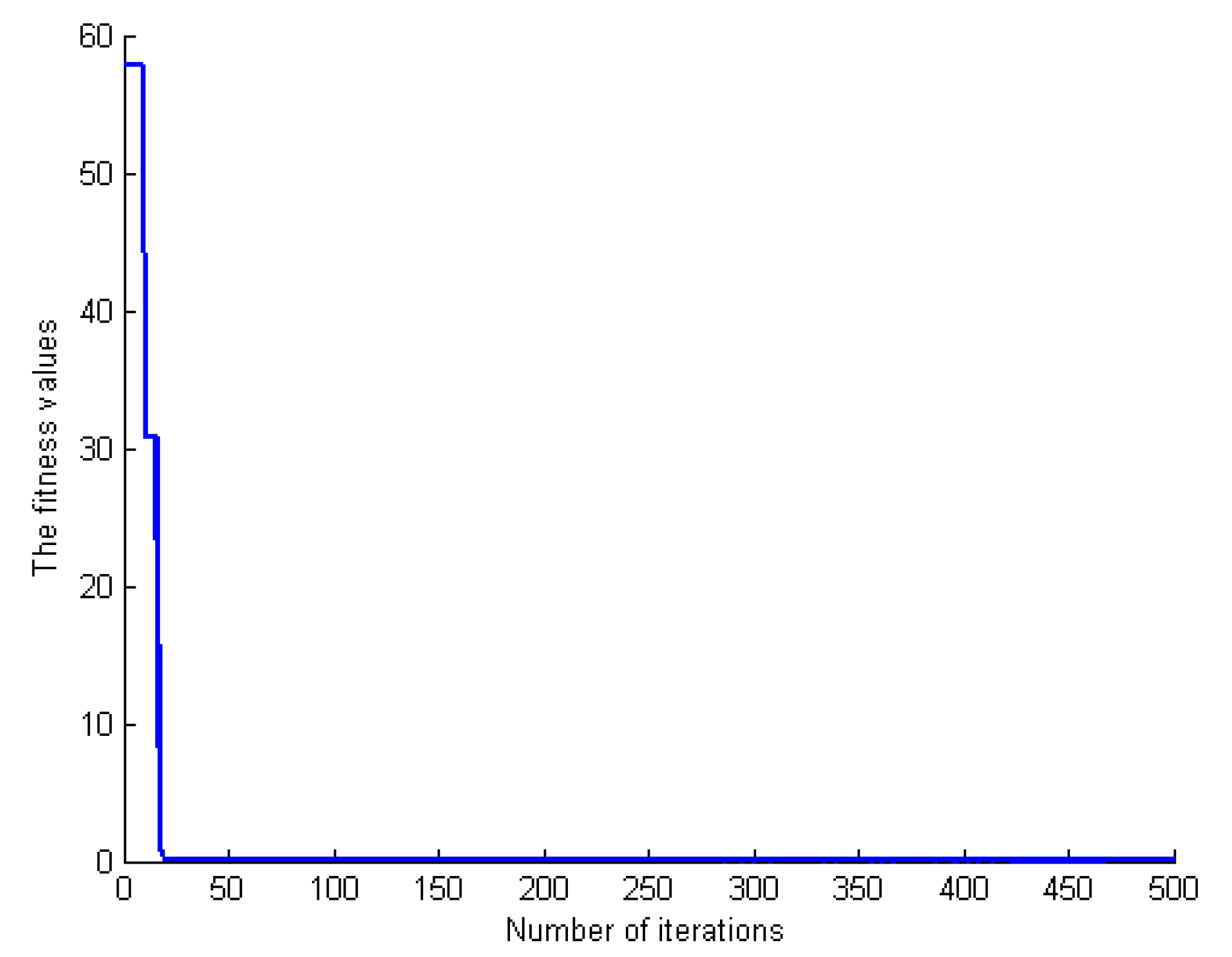
3.3. Parameter Optimization of Permanent Magnet Braking Device

According to the friction work and the energy conservation theorem, it can be roughly calculated that the maximum braking torque of a single vehicle wheel under high load braking is about 1100 N∙m. Considering the maximum load braking, the braking torque is not completely dependent on the permanent magnet braking device. Therefore, the maximum braking torque of a single permanent magnet braking device is controlled at about 500 N∙m, which can meet the requirements of a simulation and test.
For the parameter design of a permanent magnet braking device, from the perspective of cost-saving, the fewer the number of permanent magnets, the better; from the perspective of braking performance, the permanent magnet braking device is expected to reach the maximum braking torque under the condition of meeting the dimensional requirements. Therefore, the design target conditions are determined as follows: (1) the overall product V of the permanent magnets is the minimum; (2) The braking torque Ty of the permanent magnet braking device is the maximum. The optimization objective equations of the permanent magnet brake device can be obtained as follows:
{ min V = min ( a 1 w 1 h 1 + a 2 w 2 h 2 ) max T y = T o u t + T i n = 500
According to the main dimensional parameters of the permanent magnet braking device determined in Section 3.2, the constraints are as follows:
{ π ( r 1 h 1 l g ) N p + 1 1.3 w 1 π ( r 1 h 1 l g ) N p 0 1.4 a 1 l w 0.008 h 1 0.020 w 1 = 1.2 w 2 h 1 = h 2
Based on particle swarm optimization (PSO), the parameters of the double rotor permanent magnet braking device are optimized.
Relevant parameters are set based on PSO, as follows:
(1)
The total number of particles in the population: N = 400.
(2)
Maximum number of iterations: kmax = 500.
(3)
Inertia weight ω can be expressed as:
ω = ω max ( k 1 ) ( ω max ω min ) ( k max 1 )
where ωmax is the maximum weight, which is taken as 1.2; ωmin is the minimum weight, which is taken as 0.5; and k is the number of iterations.
(4)
The acceleration factors c1 and c2 are set as: c1 = c2 = 2.
After particle swarm optimization, the fitness curve of the total objective function is shown in Figure 6.
After PSO optimization, the corresponding values of the axial length, circumferential width, and radial height of the inner and outer permanent magnets are shown in Table 2.

4. Magnetic Field Analysis of a Double Rotor Permanent Magnet Braking Device

The structural parameters of the designed double rotor permanent magnet braking device are shown in Table 3.

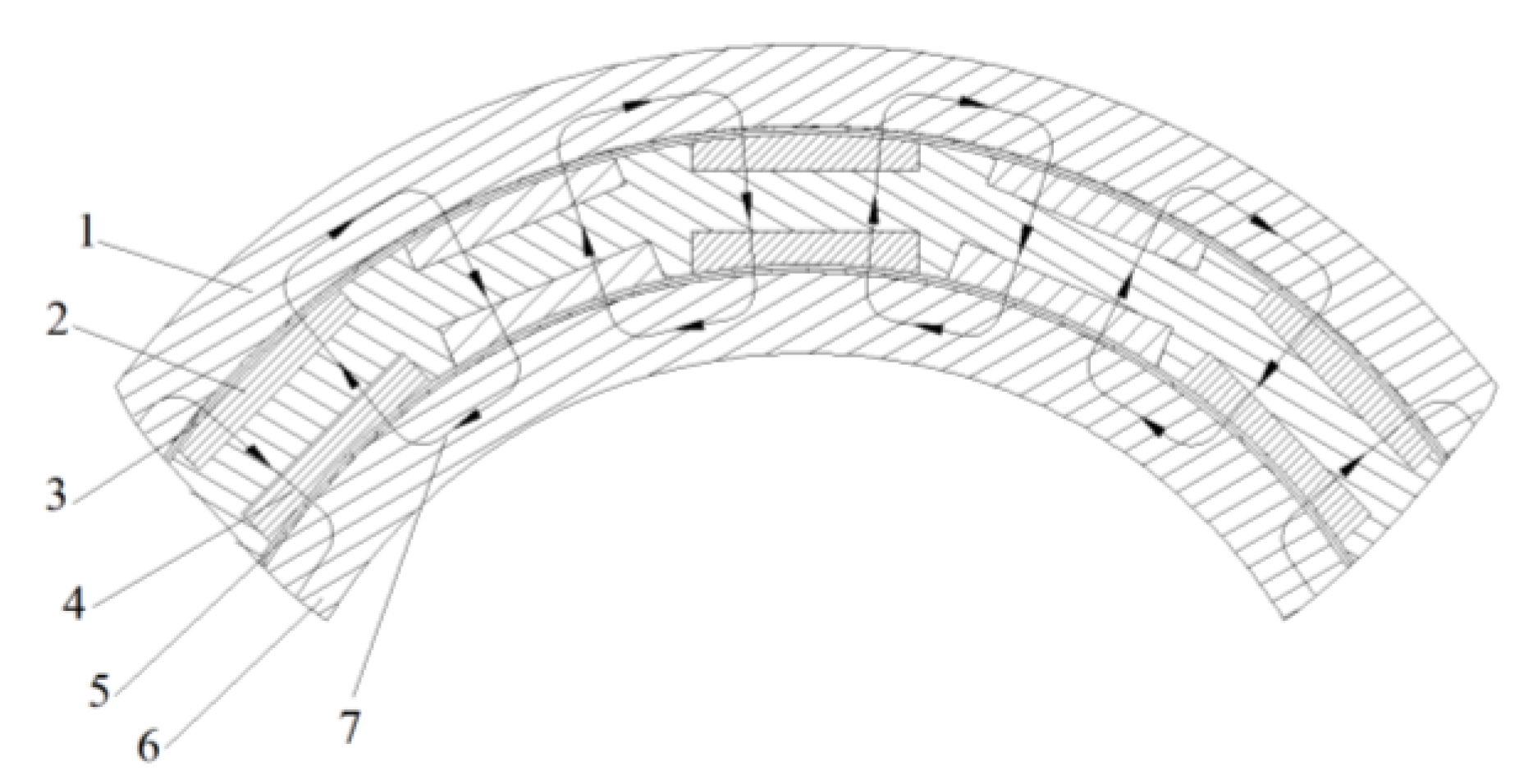
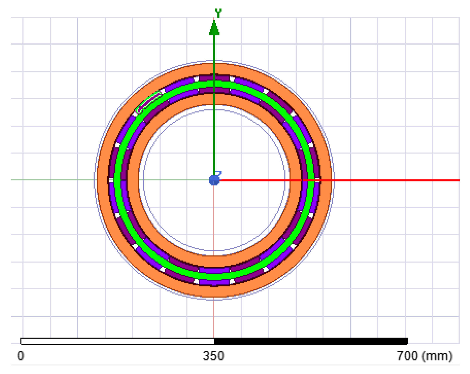
4.1. Modeling of Permanent Magnet Braking Device

The designed double rotor permanent magnet braking device belongs to a three-dimensional device, but because the device has circumferential symmetry, in order to save analysis and calculation time, the two-dimensional magnetic field analysis method can also meet the design requirements. The two-dimensional model established according to the structural parameters of the double rotor permanent magnet braking device is shown in Figure 7.

4.2. Material Properties and Model Meshing

The rotor drum of the permanent magnet braking device is not only the conductor that produces eddy currents, but also the main component for outputting the braking torque. Therefore, the rotor drum should be made of metal materials with high strength, superior magnetic conductivity, and electrical conductivity. Generally, 12CrMoV is selected, and its material property parameters are shown in Table 4. The material property parameters of other components are shown in Table 5.
In the double rotor permanent magnet braking device, the eddy current is mainly generated by the copper coating on the rotor drum. Therefore, the copper coating needs to be divided into separate fine grids, and the maximum length of the grids is 0.8 mm. For the grid division of the air area, permanent magnet, bracket, and rotor drum (excluding the copper coating) in the model, the adaptive grid division method is adopted. The grid division of the double rotor permanent magnet braking device is shown in Figure 8.

4.3. Excitation Source and Boundary Conditions

Because the permanent magnets are used as the excitation source in the double rotor permanent magnet braking device, attribute materials have been added when establishing the finite element model, so there is no need to add additional materials when determining the excitation source.
The boundary conditions are vector magnetic potential boundary conditions. The vector magnetic potential boundary condition indicates that the normal projection of the vector magnetic potential on the boundary is constant. Generally, the constant of a normal projection is 0, indicating that it is non-magnetic outside the boundary, so as to reduce the amount of calculation. The outer rotor drum and the copper-clad layer are set with 0 current excitations, because the axial length of the permanent magnet braking device is limited, and the eddy current in the outer rotor drum and the copper-clad layer forms a loop, so the currents on the cross-section of the object have positive and negative directions, and the sum of positive and negative currents is equal to zero. To correctly calculate the eddy current in the object, the corresponding object should be given 0 current.

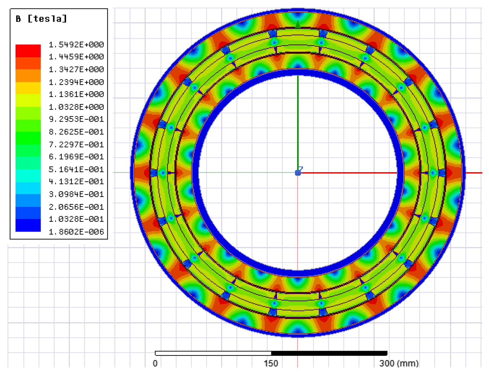
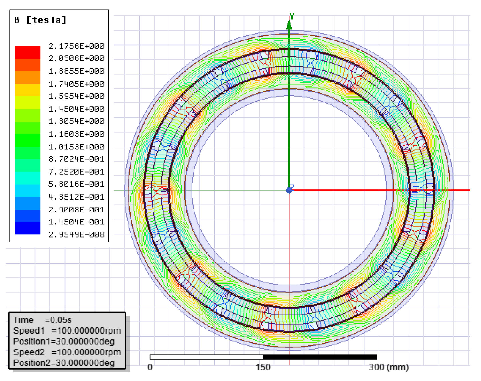
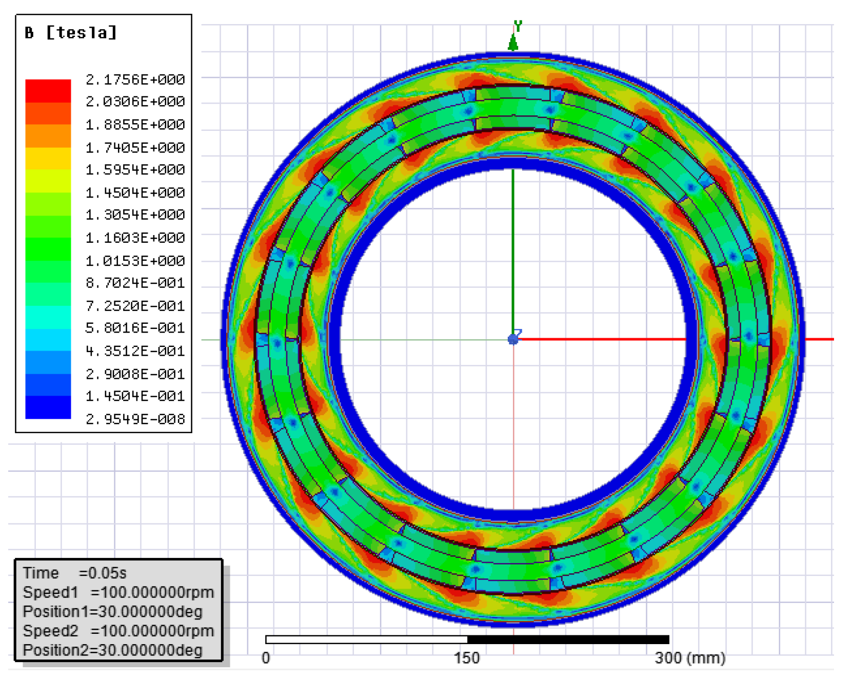
4.4. Analysis Results of Static Magnetic Field

The permanent magnets are distributed on the inner and outer sides of the stator, and the polarity of adjacent magnets is opposite. The cloud diagram of a magnetic force line distribution under a static magnetic field is shown in Figure 9, the cloud diagram of eddy current density is shown in Figure 10, and the cloud diagram of magnetic density is shown in Figure 11.
As can be seen from Figure 9, the magnetic force lines of two permanent magnets with the same polarity inside and outside coincide. After passing through the air gap, they enter the copper-clad layer and rotor drum, then come out of the rotor drum and copper-clad layer, pass through the air gap and enter the adjacent permanent magnets with opposite polarity. At this time, since the rotor drum does not rotate, there is no movement of cutting the magnetic force lines, so there is no braking torque. As can be seen from Figure 10, no eddy current is generated in the static magnetic field, so the braking torque will not be generated due to the eddy current effect. As can be seen from Figure 11, the maximum magnetic density at this time is distributed between two adjacent magnetic poles, and the distribution in the whole permanent magnet braking device is relatively regular. The static magnetic field can only be used to analyze the magnetic force lines, magnetic density, and flux density, but the generation of the braking torque needs to rotate the rotor drum and cut the magnetic force lines. Therefore, it is necessary to analyze the transient magnetic field of the double rotor permanent magnet braking device to study the braking torque.

4.5. Analysis Results of Transient Magnetic Field

When analyzing the transient magnetic field of the double rotor permanent magnet braking device, the transient analysis is selected as the solution type, and the inner and outer rotor drums and their copper-clad layers are set as moving parts to analyze the magnetic field changes of the rotor drum at different speeds. The cloud diagram of magnetic force line distribution under a transient magnetic field is shown in Figure 12, and the magnetic density cloud diagram of the rotor drum with a speed of 100 rpm is shown in Figure 13.
It can be seen from Figure 12 and Figure 13 that the positions of the magnetic force lines under the transient magnetic field have changed compared with the static magnetic field, and the magnetic force lines are pulled obviously due to the rotation of the rotor drum with cutting the magnetic force lines. At this time, the maximum magnetic density is in the rear half of permanent magnets. From the magnetic density distribution in the figure, there is an obvious rotation trend.
The cloud diagrams of the eddy current density distribution at different speeds are shown in Figure 14. As can be seen from Figure 14, the maximum eddy current density at 100 rpm is 1.3879 × 10⁸ A/m2, the maximum eddy current density at 500 rpm is 5.4529 × 10⁸ A/m2, and the maximum eddy current density at 1000 rpm is 7.4283 × 10⁸ A/m2. Therefore, it can be seen from the change of eddy current density that with the increase in rotating speed, the eddy current density becomes larger and larger, which is consistent with the calculation formula of eddy current density.
With the increase in rotating speed, the braking torque of the permanent magnet braking device also changes. When the rotating speed is 1000 r/min, the braking torque curve is shown in Figure 15, and the braking torque curve with the rotating speed is shown in Figure 15.
It can be seen from Figure 15 that the braking torque oscillates first, and the fluctuation becomes smaller and smaller and gradually stabilizes with the passage of time. This is because, at the initial stage of the magnetic field, the change of magnetic flux is the largest, resulting in a huge peak value of the braking torque. With the stability of magnetic flux change, the braking torque stabilizes near the maximum value. When the speed is 1000 r/min, the corresponding maximum braking torque is about 495 N·m, which is close to the theoretical calculation value of the mathematical model under this size, and the deviation is small, which further demonstrates the accuracy of the simulation.

5. Conclusions

Based on the analysis of the research status of permanent magnet braking devices at home and abroad, a double rotor permanent magnet braking device was proposed and analyzed by the finite element method, which provided a theoretical basis for the design of a permanent magnet braking device.
(1)
A design scheme of a double rotor permanent magnet braking device was proposed, and its main structural parameters were designed and calculated.
(2)
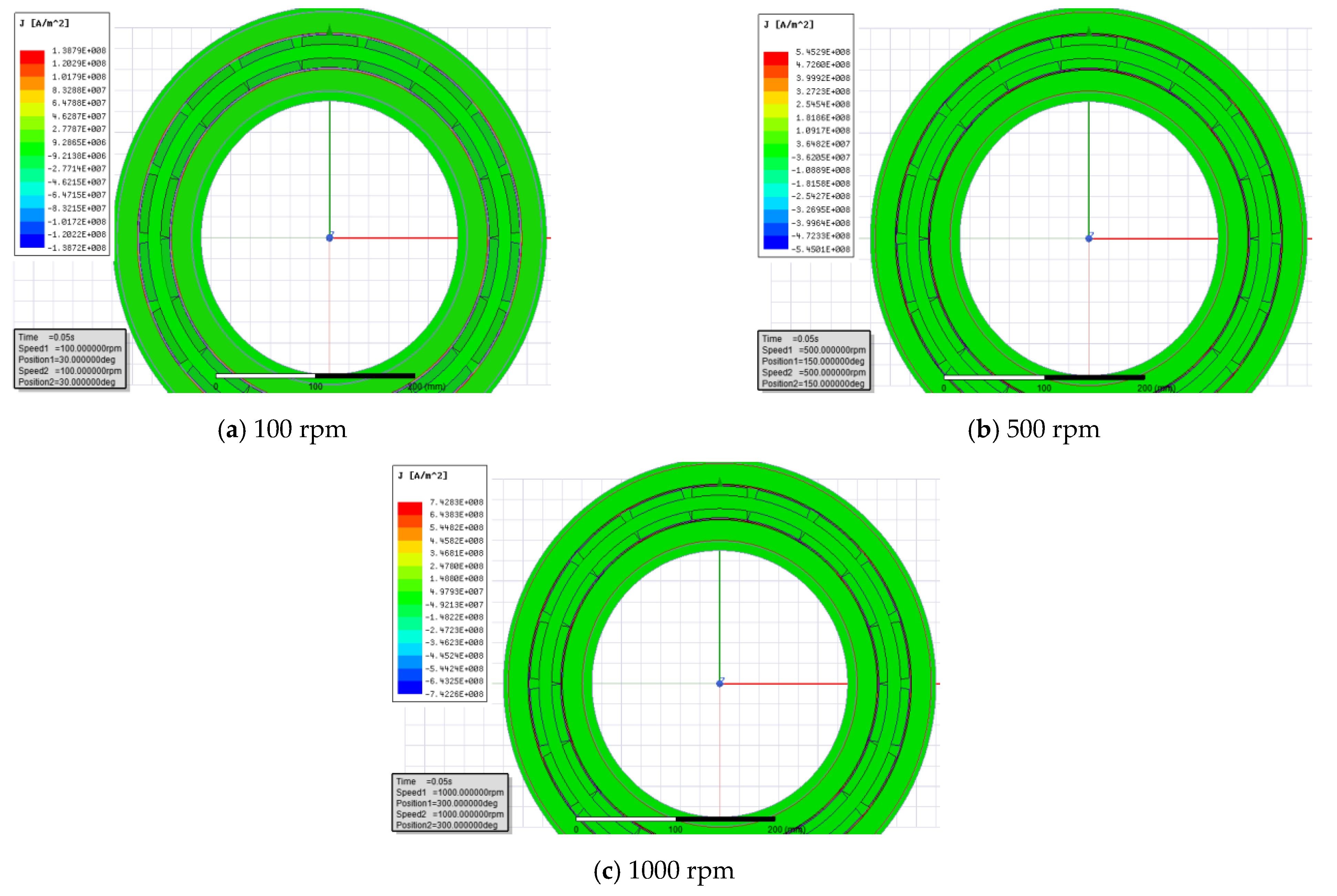
The two-dimensional finite element model of the double rotor permanent magnet braking device was established, and its static magnetic field and transient magnetic field were analyzed. The analysis results show that the eddy current density increases with the increase in rotating speed, which is consistent with the theoretical calculation value.
(3)
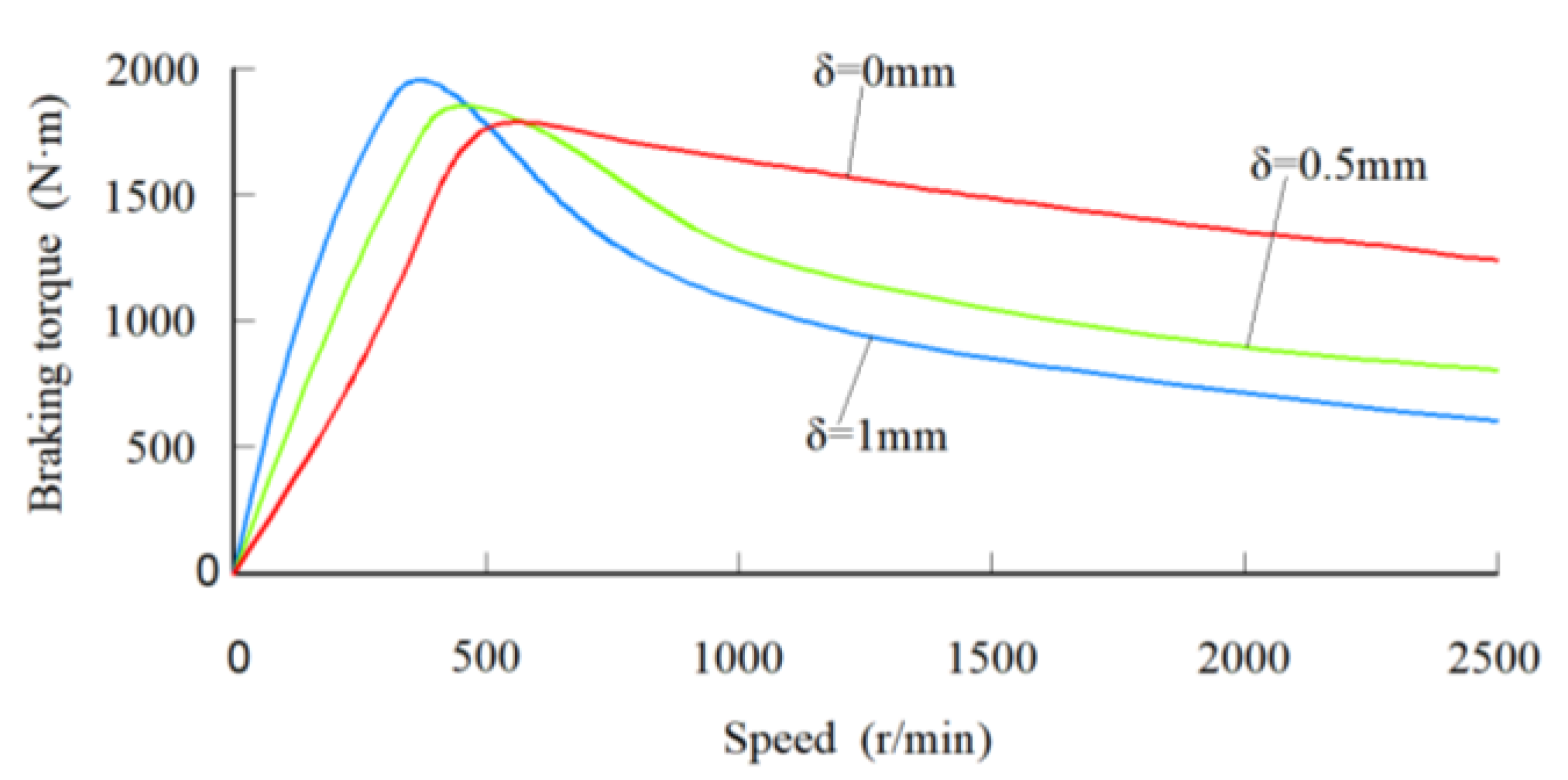
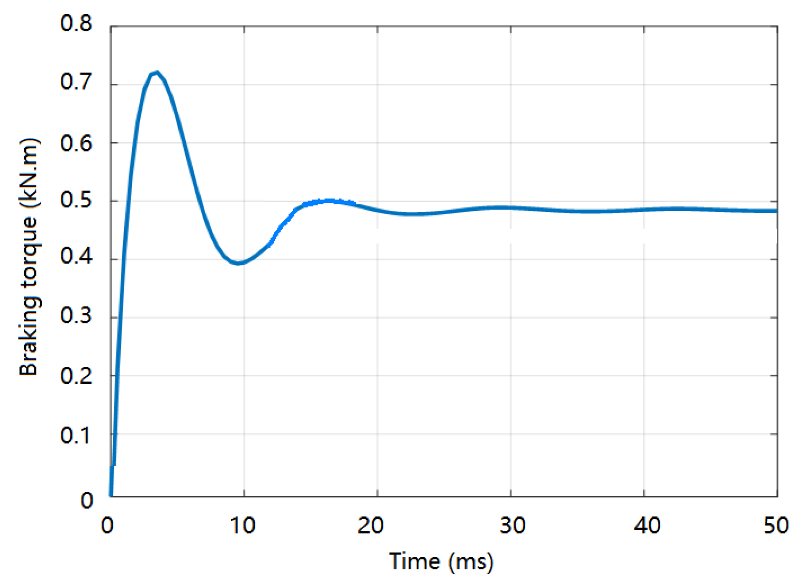
The braking performance of the double rotor permanent magnet braking device was analyzed. The analysis results show that the maximum braking torque is close to the theoretical calculation value, the braking torque changes with the change of speed, and the maximum braking torque occurs in the low-speed region.

Author Contributions

Conceptualization, J.T. and Y.Z.; methodology, J.T.; software, J.T.; validation, J.T. and Y.Z.; formal analysis, Y.Z.; investigation, J.T.; resources, Y.Z.; data curation, J.T.; writing—original draft preparation, J.T.; writing—review and editing, J.T.; visualization, J.T.; supervision, Y.Z.; project administration, J.T.; funding acquisition, J.T. All authors have read and agreed to the published version of the manuscript.

Funding

This research was funded by the Industry University Research Cooperation Foundation of Jiangsu Province (grants BY2019062), the Research and Innovation Foundation of General University Graduate of Jiangsu Province (grants KYLX_1024), and the Overseas Training Foundation for Universities of Jiangsu Province.

Institutional Review Board Statement

Not applicable.

Informed Consent Statement

Not applicable.

Data Availability Statement

Not applicable.

Conflicts of Interest

The authors declare no conflict of interest.

References

  1. He, R.; Zhang, R.J. A Brake and Braking Method Combining Permanent Magnet Braking and Friction Braking. Chinese Patent CN102155508b, 13 March 2013. [Google Scholar]
  2. Wang, K.Y.; He, R.; Tang, J.H.; Liu, R. Design and thermal analysis of a novel permanent magnet-friction integrated brake for vehicle. Therm. Sci. 2020, 24, 1827–1834. [Google Scholar] [CrossRef]
  3. Liu, C.; Zhao, Y.; Wang, Y.; Zhang, T.; Jia, H. Hybrid dynamic modeling and analysis of high-speed thin-rimmed gears. J. Mech. Des. 2021, 143, 123401. [Google Scholar] [CrossRef]
  4. Wang, K.Y.; He, R.; Tang, J.H.; Liu, R. Performances Analysis of a novel electromagnetic-frictional integrated brake based on multi-physical fields coupling. World Electr. Veh. J. 2019, 10, 9. [Google Scholar] [CrossRef] [Green Version]
  5. Liu, S.; Liu, C.; Huang, Y.; Xiao, Y. Direct modulation pattern control for dual three-phase pmsm drive system. IEEE Trans. Ind. Electron. 2022, 69, 110–120. [Google Scholar] [CrossRef]
  6. Yang, W.; Lin, Y.; Chen, X.; Xu, Y.; Song, X. Wave mixing and high-harmonic generation enhancement by a two-color field driven dielectric metasurface. Chin. Opt. Lett. 2021, 19, 123202. [Google Scholar] [CrossRef]
  7. Shi, M.; Zhu, H.; Yang, C.; Xu, J.; Yan, C. Chemical reduction-induced fabrication of graphene hybrid fibers for energy-dense wire-shaped supercapacitors. Chin. J. Chem. Eng. 2021, 5, 45. [Google Scholar] [CrossRef]
  8. Dong, H.; Zhao, B.; Deng, Y. Instability phenomenon associated with two typical high speed railway vehicles. Int. J. Non-Linear Mech. 2018, 105, 130–145. [Google Scholar] [CrossRef]
  9. Tu, K. Research on the Electromagnetic and Friction Integrated Brake with Variable Air Gap Width in Passenger Car; Jiangsu University: Zhenjiang, China, 2017. [Google Scholar]
  10. Zhao, X.B.; Ji, C.Y.; Huang, Y.Q.; Zhou, J. Eddy current analysis and braking moment calculation of permanent magnet typed eddy current retarder. J. Mach. Des. 2008, 25, 62–65. [Google Scholar]
  11. Zuo, J.Y.; Tian, X.Y. Calculation of effective parameters of inductor eddy current dynamometer. Large Electr. Mach. Hydraul. Turbine. 1972, 2, 31–42. [Google Scholar]
  12. Wouterse, J.H. Critical torque and speed of eddy current brake with widely separated soft iron poles. IEE Proc.-B 1991, 138, 153–158. [Google Scholar] [CrossRef]
  13. Wang, J. Research on Structure Design Method of Braking Torque Graded Permanent Magnet Retarder; Jiangsu University: Zhenjiang, China, 2017. [Google Scholar]
  14. He, R.; Wang, J.; Wang, L. Design of graded permanent magnet retarder. J. Chongqing Jiaotong Univ. (Nat. Sci.) 2015, 34, 155–159. [Google Scholar]
  15. Ye, L.Z.; Liu, Y.P.; Cao, M.G.; Li, D.S. Braking characteristics and experiment of a permanent magnet eddy-current retarder. J. Beijing Univ. Technol. 2018, 44, 837–842. [Google Scholar]
Figure 1. Double rotor permanent magnet braking device. 1—wheel; 2—brake caliper body; 3—friction block; 4—outer permanent magnets; 5—inner permanent magnets; 6—brake disc; 7—half shaft; 8—electromagnetic clutch; 9—connecting part; 10—thermal insulation element; 11—outer rotor drum; 12—outer copper coating; 13—bracket; 14—inner copper coating; 15—thermal insulation element; 16—inner rotor drum; 17—half shaft flange; 18—hub.
Processes 10 00346 g001
Figure 2. Internal structure of the electromagnetic clutch. 1—electromagnetic coil; 2—friction plate; 3—armature; 4—leaf spring; 5—driven plate; 6—rolling bearing; 7—half shaft; 8—rolling bearing; 9—driving plate.
Processes 10 00346 g002
Figure 3. Relation curves of the air gap with magnetic flux density and braking torque.
Processes 10 00346 g003
Figure 4. Local schematic diagram of permanent magnet braking device with copper coating. 1—outer rotor drum; 2—outer permanent magnet; 3—outer air gap; 4—inner permanent magnet; 5—inner air gap; 6—inner rotor drum; 7—magnetization direction.
Processes 10 00346 g004
Figure 5. Relationship curves of copper coating thickness, rotor drum speed, and braking torque.
Processes 10 00346 g005
Figure 6. The fitness curve of the total objective function.
Processes 10 00346 g006
Figure 7. Two-dimensional model of the permanent magnet braking device.
Processes 10 00346 g007
Figure 8. Mesh division of the permanent magnet braking device.
Processes 10 00346 g008
Figure 9. Cloud diagram of magnetic force line distribution.
Processes 10 00346 g009
Figure 10. Cloud diagram of eddy current density.
Processes 10 00346 g010
Figure 11. Cloud diagram of magnetic density.
Processes 10 00346 g011
Figure 12. Cloud diagram of magnetic force line distribution.
Processes 10 00346 g012
Figure 13. Magnetic density nephogram of the rotor drum at 100 rpm.
Processes 10 00346 g013
Figure 14. Cloud diagram of eddy current density distribution at different speeds.
Processes 10 00346 g014
Figure 15. Braking torque curve at 1000 r/min.
Processes 10 00346 g015
Table 1. Some vehicle parameters of the selected model.
ParametersValuesParametersValues
Curb weight m (Kg)5770Wheelbase L (m)4.2
Minimum ground clearance h (m)0.26Overall dimension (m)7.015 × 2.470 × 2.510
Front axle load Gf (Kg)2410Rear-axle load Gr (Kg)3360
Table 2. Main parameter values of the optimized permanent magnets.
ParametersNpw (mm)h (mm)a (mm)
Outer permanent magnet8501531
Inner permanent magnet8501526
Table 3. Structural parameters of the designed double rotor braking device.
ParametersValues
Outer radius of outer rotor drum (mm)203
Outer radius of inner rotor drum (mm)143
Thickness of rotor drum (mm)10
Thickness of copper clad layer (mm)1
Air gap between copper clad layer and permanent magnet (mm)1
Outer diameter of outer permanent magnet (mm)191
Outer diameter of inner permanent magnet (mm)160
Thickness of magnet bracket (mm)46
Table 4. Material property parameters of rotor drum.
ParametersValuesParametersValues
Density ρ (kg/m3)7870Thermal conductivity k (W/(m·K))54.7
Conductivity σ (S/m)6 × 106Thermal diffusivity α (m2/s)2.31 × 10−5
Relative permeability μr200Specific heat capacity Cd (J/(kg·K))574
Table 5. Material property parameters of other components.
ComponentsPermanent MagnetBracketCopper Clad Layer
MaterialsNF38Mild steelCopper
Coercivity Hc (A/m)9.07 × 105
Relative permeability μr1.09930000.999
Conductivity σ (S/m)0.2 × 1075.8 × 107
Publisher’s Note: MDPI stays neutral with regard to jurisdictional claims in published maps and institutional affiliations.

