Abstract
The effect of tilt angle on free convection heat transfer is investigated experimentally inside a rectangular parallelepiped cavity filled with water. The cavity had the dimensions S × S × H (m3), where S was the inside length, and H was the inside height of the cavity. The lower surface was subject to constant heat flux, and the upper surface was cooled by a stream of ambient air. The free convection heat transfer data were generated using different uniform heat fluxes. Four tilt angles were considered: . The surface temperature measurements were collected 10 h after the experimental run to ensure that a steady-state was reached. It was noticeable that the free convection heat transfer strongly depended on the tilt angle and the modified Rayleigh numbers. The 3D results showed that the Nusselt number reached a maximum at 60° at a fixed modified Rayleigh number. An enhancement in the Nusselt number at any tilt angle was observed over that of a zero tilt angle, and the percent of enhancement was 7.92–62.38%, depending on the modified Rayleigh numbers and the tilt angle. It was also observed that as the modified Rayleigh number increased, the temperature uniformity on both the hot and cold surfaces was disturbed. Furthermore, an empirical correlation between the modified Rayleigh numbers and Nusselt numbers was obtained for each angle. Moreover, two overall general correlations are obtained to cover the four tilt angles (i.e., 0°, 30°, 60°, and 90°) and the modified Rayleigh numbers, which should be helpful for engineering applications.
1. Introduction
The study of free convection in enclosures has extensive application in numerous fields. Applications include thermal insulation for buildings, solar collectors, cooling systems for nuclear reactors, and convective processes in lakes [1,2,3]. Natural convection is a heat transfer mode that arises due to the buoyancy-induced flows occurring from temperature gradients within fluids. Most of the research on cavities was mainly obtained using the classical Rayleigh–Bénard problem and in settings where a vertical wall was heated and the opposite wall was kept at a cooler temperature. However, in a variety of engineering applications, cavities are inclined with respect to the direction of the gravity vector. Hence, the buoyancy force has both components relative to the walls of the enclosure, which strongly modifies the flow structure and the heat transfer therein [4]. A comprehensive review of the studies on free convection in cavities was carried out by Pandey et al. [5]. The effects of internal bodies with different shapes (e.g., square, circular, and an elliptical cylinder) on free convection heat transfer were also summarized. The literature survey showed that studied enclosures were filled either with liquid water or air. Therefore, the enclosures filled with water are cited first followed by those filled with air. A natural dimensionless heat transfer coefficient inside two water-filled square cavities was investigated experimentally by Ali et al. [6]. Average Nusselt and modified Rayleigh numbers were established for each enclosure. Special correlations were obtained for each enclosure, and a general correlation was obtained for both of them using the aspect ratio (κ = S/H) and the modified Rayleigh number as:
Imberger [7] experimentally studied the variation in the heat transfer coefficient on free convection developed inside a horizontal cavity filled with water and having aspect ratios of 0.01 and 0.19. In his experiment, the vertical walls were differentially heated. Bejan and Al-Homoud [8] experimentally studied heat transfer in a horizontal rectangular cavity for a 0.0625 aspect ratio and for a Rayleigh number range of where the two vertical ends were kept at different temperatures with long horizontal adiabatic walls. Ozoe et al. [9] conducted a 2D laminar numerical simulation of a rectangular cavity filled with water, for two different aspect ratios, and for different Rayleigh numbers up to 109. Valencia et al. [10] have reported experimentally and numerically the natural convection in a cubical cavity filled up with water, but with partially conducting lateral walls. In their study, the calculated time averaged-velocity field of the turbulent Rayleigh–Be’nard flow structures were compared with those measured experimentally. During their studies, Boussinesq and finite volume approximations were used to numerically simulate the heat transfer. Mostafa [11] et al. reported numerically and experimentally the free convection heat transfer in a closed enclosure filled with water and with vertical heated walls. Those walls were heated and cooled using two special heat exchangers. The other walls were assumed insulated. Their 2D simulation results did not capture the streamlines properly for all used Rayleigh numbers.
Now turning the reader’s attention to the enclosures filled with air, Kuznetsov and Sheremet [12] numerically studied the convection and radiation heat transfer due to the conductive walls’ enclosure. That enclosure was locally heated at the bottom. The effects of different parameters were taken care of during the simulation of the streamlines and temperature profiles. The correlation ratio for the average Nusselt number was obtained at Pr = 0.702. Other researchers have studied the natural convection of heat transfer inside a cavity filled with air for different parameters [13,14,15,16,17,18,19,20]. Hasnaoui et al. [21] studied the natural convection heat transfer in rectangular cavities partially heated from below using a finite difference method. The effects of thermophysical and geometrical parameters were investigated for different Rayleigh numbers and Prandtl numbers. Varol et al. [22] studied the effect of entropy generation due to the free laminar convection inside a square room, which was partly cooled. That study was accomplished using support vector machines, where the room was simulated as a heated flat with windows. In their study, convection-governing equations were solved using a finite difference technique to achieve the velocity and temperature fields. Deng [23] numerically investigated 2D laminar-free convection in a square cavity. The walls of the cavity were heated using discrete heat source–sink pairs. Corcione [24] numerically investigated natural convection in a rectangular enclosure chilled from the upper surface and heated from the bottom. The sidewalls were studied at different boundary conditions. His results presented various correlations for diverse thermal configurations of the sidewalls. Calcagni et al. [25] experimentally and numerically studied the free convection of square enclosures. The lower and sidewalls were heated and chilled, respectively.
The objective of the current experimental research was to study the three-dimensional effects of tilt angle on the free convection heat transfer of a rectangular parallelepiped cavity filled with distilled water. Based on the above literature review, an in-depth empirical study was required to examine this phenomenon and to determine how the Nusselt number will change with modified Rayleigh numbers at various tilt angles in natural convection in a distilled-water-filled enclosure. It should be noted that from the literature survey above, most of the studies were concentrated either numerically or experimentally on the enclosures heated from the side. In addition, almost all the numerical studies involved 2D analyses. However, in the current study, the enclosure was a wide 3D enclosure heated from the bottom, where we traced the development of the natural convection Nusselt number from the horizontal position of the cavity up to the vertical position through 0°, 30°, 60°, and 90° tilt angles. Two new empirical correlations for Nusselt numbers that cover all of the tilted angles are reported, using the tilt angle and Rayleigh numbers as parameters.
2. Experimental Setup
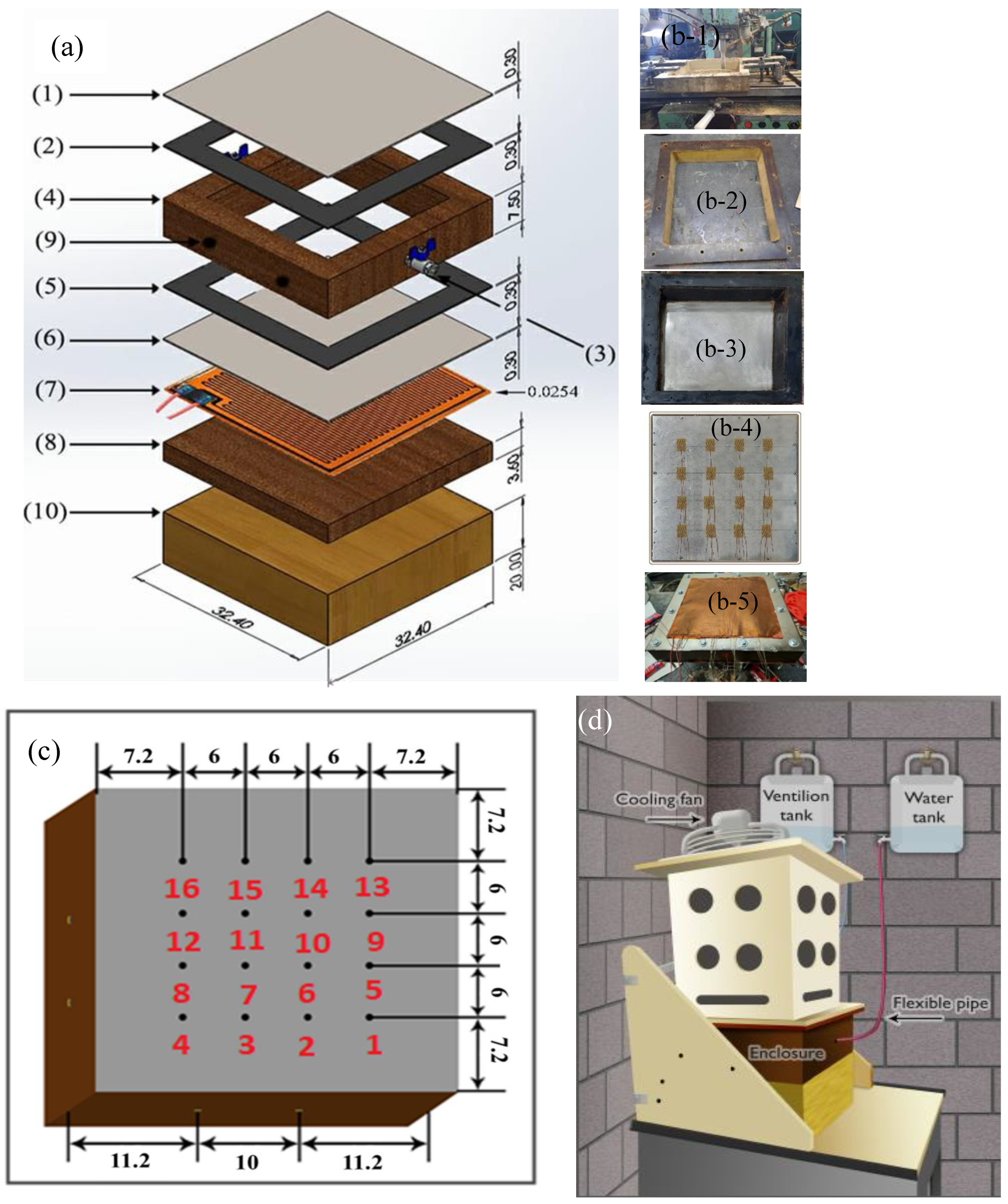
An experimental test rig was designed to hold the rectangular parallelepiped cavity. The main parts of the cavity are shown in detail in Figure 1a–d and listed in Table 1. As shown in Figure 1a–d, the cavity was made from Bakelite (k = 0.15 W/(m·k) [26]) using interior dimensions of 30 × 30 cm2 and a depth of 7.5 cm. The exterior dimensions were 32.4 × 32.4 cm2. The enclosure was inserted between two stainless-steel plates (nos. 1 and 6 in Figure 1a) with the dimensions 32.4 × 32.4 × 0.3 cm (k = 16.4 W/(m·k) [26]). Two sheets of gasket (nos. 2 and 5 in Figure 1a) were inserted between the stainless-steel plates and the enclosure to prevent any possible leakage. Figure 1a also shows two valves (no. 3) in the sides of the enclosure (no. 4) for filling and ventilation. A flexible-type foil heater (no. 7) (30 × 30 cm2), which had a thickness of 2.54 × 10⁻⁴ m, was inserted in the lower stainless-steel plate. The other side of the heater was insulated by a 3.6 cm thick Bakelite plate (no. 8). The upper and bottom stainless-steel plates were installed with 16 self-adhesive surface thermocouples, type-K, to measure the temperature (displayed as dots in Figure 1c). Another four thermocouples (no. 9) were installed on the lower Bakelite surface (no. 8). In addition, eight thermocouples were distributed around each enclosure’s sidewalls: two at each side, one at the outer surface, and the other inserted through the side and leveled at the inside surface to measure any possible heat loss through the enclosure’s sides. Figure 1b shows real lab photos during the manufacturing and assembling of the enclosure (Figure 1(b-1–b-5). A data acquisition system was used to transfer the thermocouple signals to a computer for thermal analysis. The electrical input power to the heater was controlled by a variac, and the consumed power was measured by a wattmeter. Eight various values of input power, corresponding to a total of eight heat fluxes, were used for the measurements at each tilt angle. The corresponding higher value of the heat flux was sufficient to raise the temperature inside the enclosure no more that 80 °C, so as not to reach the boiling temperature of water.
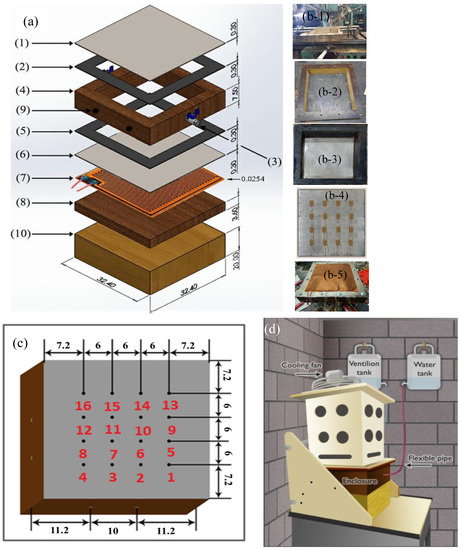
Figure 1.
Enclosure setup: (a) components—(1) top surface (stainless), (2) sealing gasket, (3) valve (two-way), (4) sidewalls, (5) sealing gasket, (6) bottom surface (stainless), (7) heater, (8) Bakelite surface, (9) thermocouples, and (10) insulation cover; (b) real photos of the manufacturing and assembling of the enclosure; (c) thermocouple locations (dimensions are in cm); (d) complete setup.

Table 1.
Enclosure parts.
3. Experimental Procedure
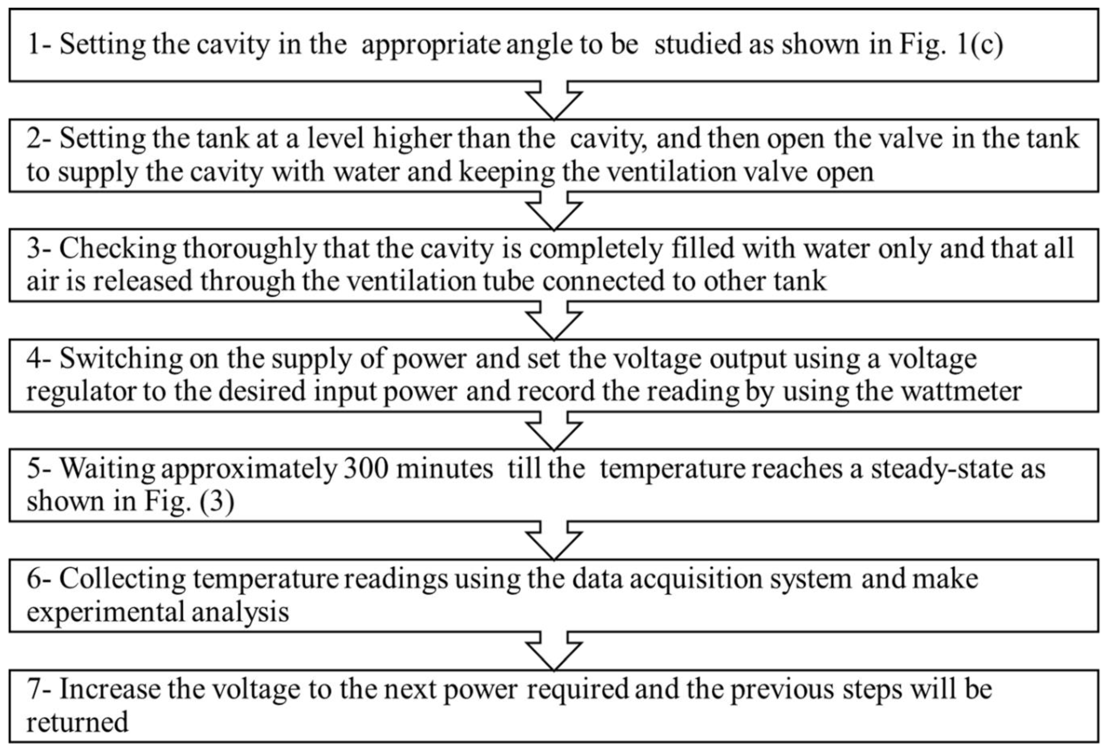
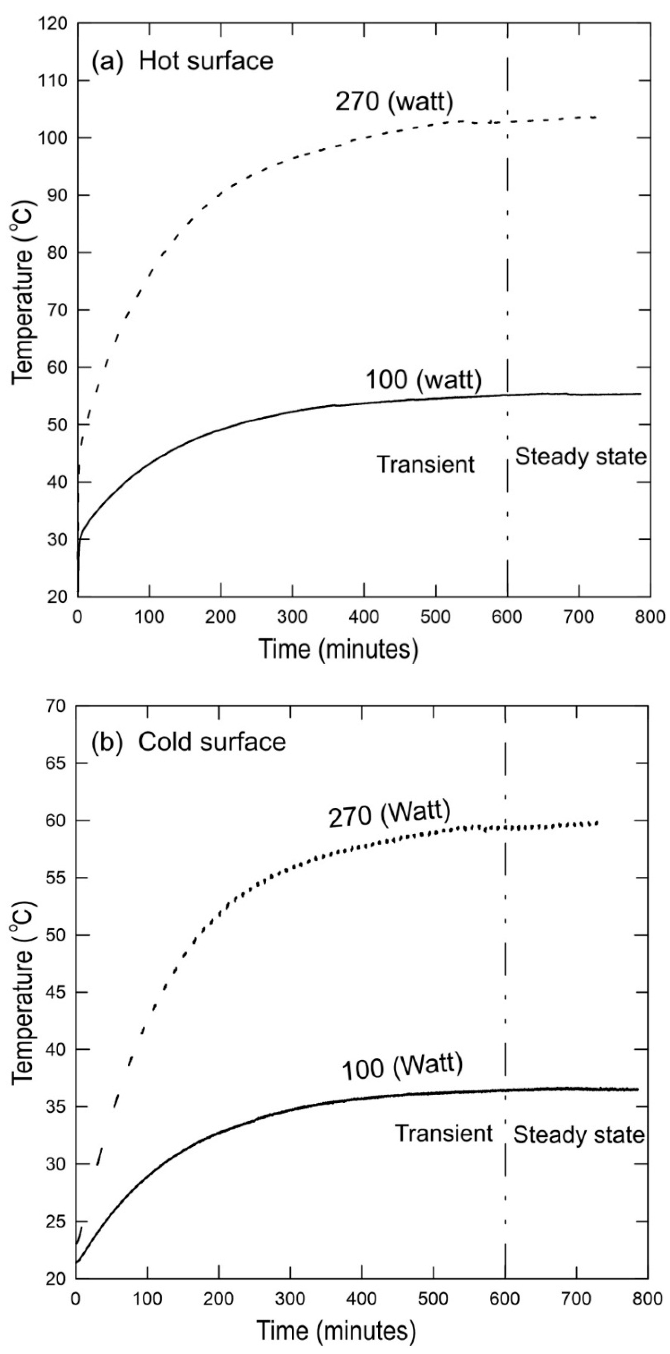
Figure 2 summarizes the necessary experimental steps to be taken before registering the temperature measurements. The temperatures at the surfaces were measured after 10 h of heating for each heat flux, as shown in Figure 3, which indeed shows that the steady-state conditions were reached after 10 h at two different applied heat fluxes. It should be noted that any more fluctuations (if any) above ten hours were obtained to be approximately only 1% of the steady-state temperature after 10 h. The experiment was conducted for heat fluxes in a range of 40–250 W.
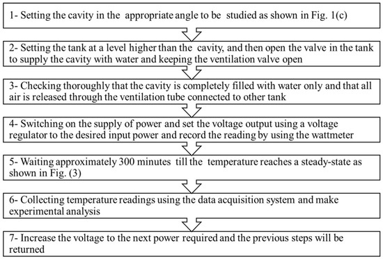
Figure 2.
Experimental steps.
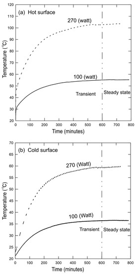
Figure 3.
Steady-state condition reached after almost 600 min: (a) hot stainless-steel surface; (b) cold stainless-steel surface.
4. Experimental Analyses
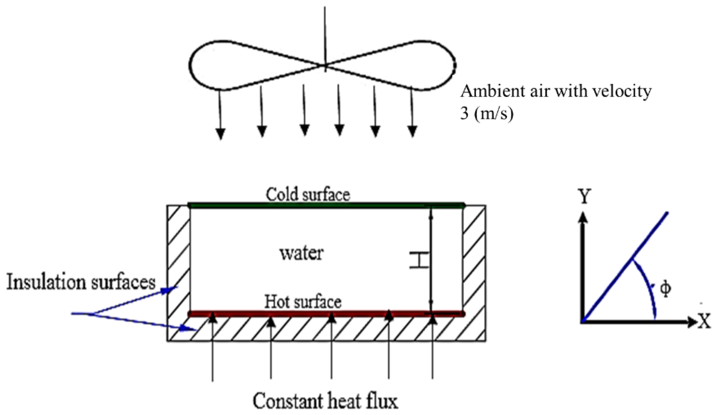
Heat transfers from the constant heat flux flexible heater were via conduction through the lower stainless-steel plate, by natural convection through the water in the cavity, conduction through the upper stainless-steel plate, and forced convection through the ambient air. In addition, the heat, which may be lost through the enclosure sides and from the heater to the lower Bakelite surface (8), was estimated and obtained, at most, to be 7.9% and 3.1%, respectively. Figure 4 shows a schematic of the experimental setup with boundary conditions that specified that the lower stainless-steel surface was subject to constant heat flux, the sidewalls were insulated, and the upper stainless-steel surface was subject to ambient air at 3.0 m/s. The net radiation heat transfer exchange between the hot and cold surfaces was calculated [27] at the maximum input power of 250 W, which corresponded to , , and = 226 W, and the shape factor between the parallel plates was F12 ≈ 0.6. The results show that the percent of radiation heat transfer to the total input power and to the convection heat rate was 3.89% and 4.3%, respectively. Therefore, the radiation heat transfer was assumed to be neglected.
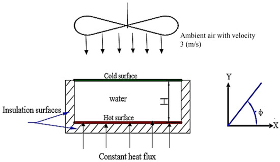
Figure 4.
Schematic of the experimental setup with boundary conditions.
The following equations were used to calculate the different amounts of heat transfer:
where Qtotal, , and are the total input electrical power and the conduction heat transfer lost through the insulated surfaces (both lower and sides) and by natural convection in the cavity, respectively. The surface areas, and , are for the insulation surface covering the heater and that of the sides, respectively.
Average Heat Transfer Coefficient
The heat transfer through the enclosure by conduction can be calculated from Fourier’s law:
It should be noted that Equation (5) uses the average surface temperatures of both the hot and cold stainless-steel surfaces. The cavity thermal resistance was calculated from:
where:
where the surface area, , is equal to the natural convection area, A, of the cavity, and = 16.4 W/(m.K) [26].
Using Equation (8), the average heat transfer coefficient through the cavity can be estimated as:
Furthermore, the Nusselt and modified Rayleigh numbers are [28]:
The thickness, H, of the cavity was used as a characteristic length in Equations (10) and (11).
5. Uncertainty Calculations
The Engineering Equation Solver (EES) [29] was used to estimate the experimental uncertainty. For some of the results, the experiment had to be repeated more than once to ensure the overall trend in the data. The error in calculating the surface area and the temperature was ±0.001 m2 and ±0.1 °C, respectively. The accuracy of the voltage measurements was taken from the manual of the wattmeter as 0.5% of reading ±2 counts with a resolution of 0.1 V, and the corresponding value for the current was 0.7% of ±5 counts read +1 mA with a resolution of 1 mA. A data acquisition system was used to register the readings of the temperatures. The average of thirty temperature scans was obtained at specified heat fluxes. The EES also provided the capability to propagate the uncertainty of the experimental data to provide uncertainty estimates for the calculated variables. The method used by the EES for determining the uncertainty follows Reference [30]. The uncertainty in the calculated quantity can be estimated as:
where U represents the uncertainty of the variable.
Temperature measurement and convection heat transfer (Qcon) were the primary sources of uncertainty. The propagating uncertainty of the heat transfer coefficient, Nusselt number, and Rayleigh number were calculated using Equations (13)–(15).
The obtained uncertainty of the results by the EES [29] software program is summarized in Table 2.
Table 2.
The uncertainty results of the variable parameters using the EES [29].
6. Results and Dissuasion
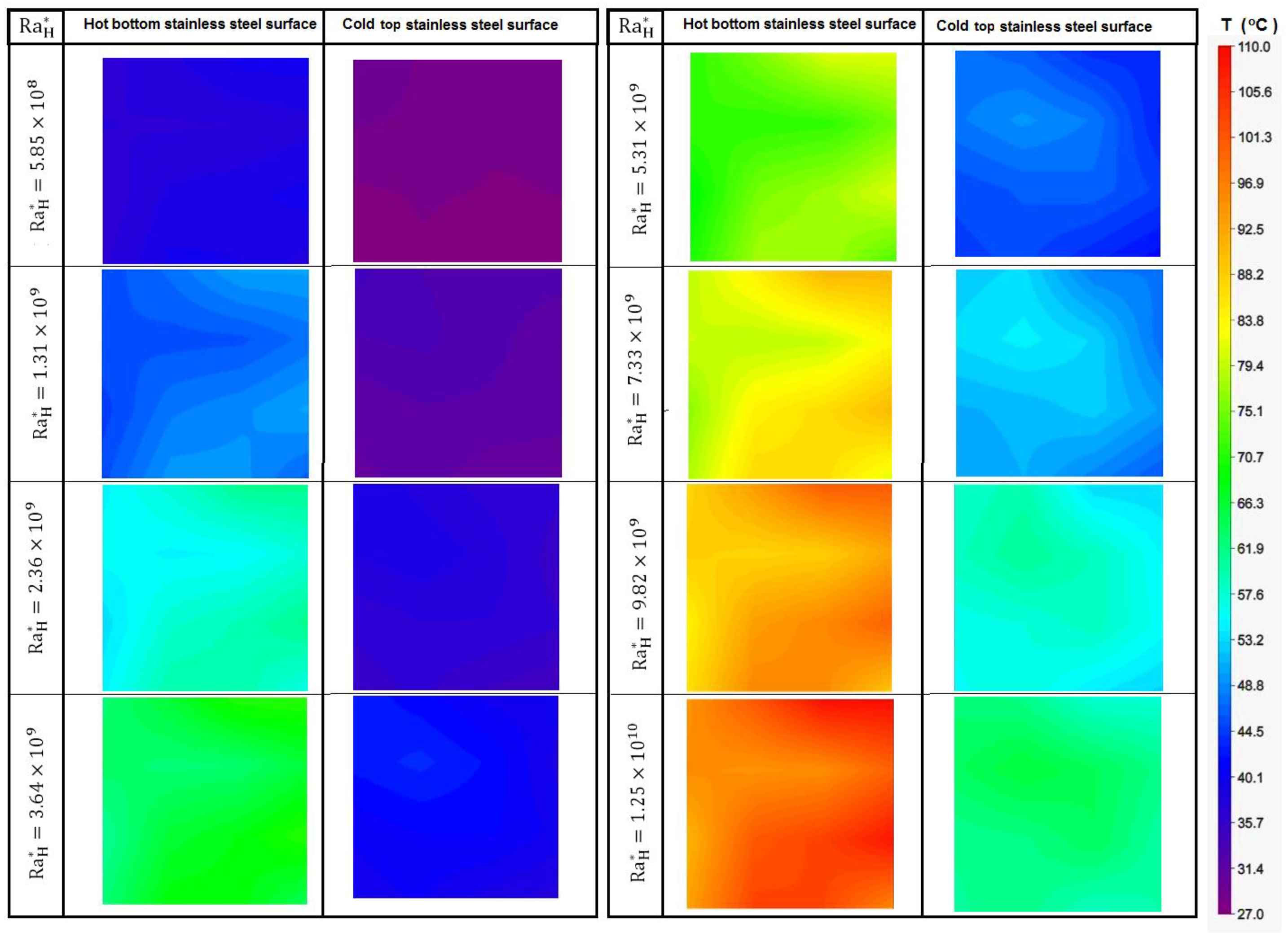
Temperature contours of the hot and cold stainless-steel surfaces at a 0° tilt angle for the cavity are shown in Figure 5, which were generated using the steady-state values measured by the sixteen thermocouples at each surface and for various modified Rayleigh numbers (. The temperature contours were Rayleigh number dependent. At low modified Rayleigh numbers, the temperature distribution on the stainless-steel surfaces was nearly uniform; at high modified Rayleigh numbers, the contours showed some variations in the surface temperatures. Similar contours were obtained for all other tilt angles (φ).
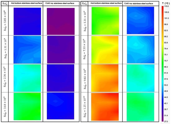
Figure 5.
Surface temperature contours of the stainless steel on the cold and hot surfaces.
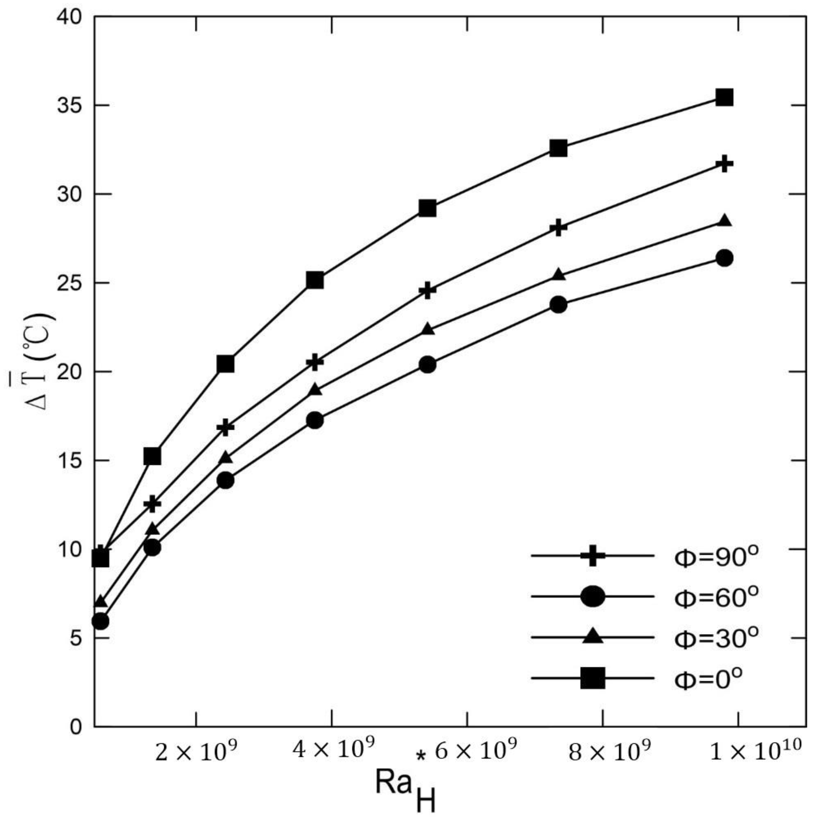
Figure 6 shows the average temperature difference between the hot and cold plates versus the modified Rayleigh numbers for different tilt angles ranging from 0° to 90°. It was clear that the average temperature increased as increased. These differences in temperature reached maximum values for the horizontal case. As the angle increases, the buoyancy effect plays an important role in reducing the temperatures according to each angle. These average temperature differences will affect the calculation of and the Nusselt numbers.
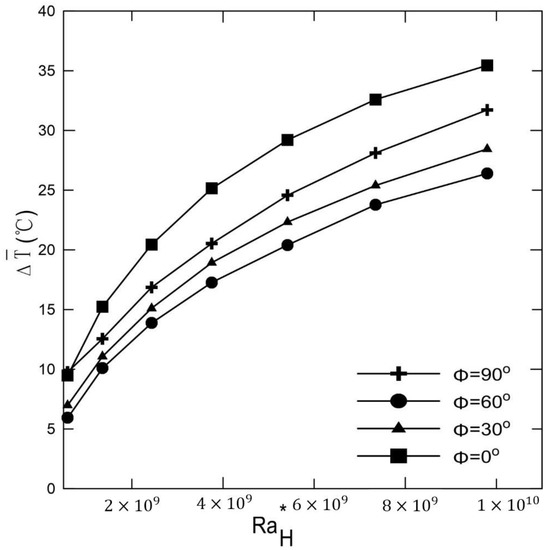
Figure 6.
Average temperature variations for different tilt angles.
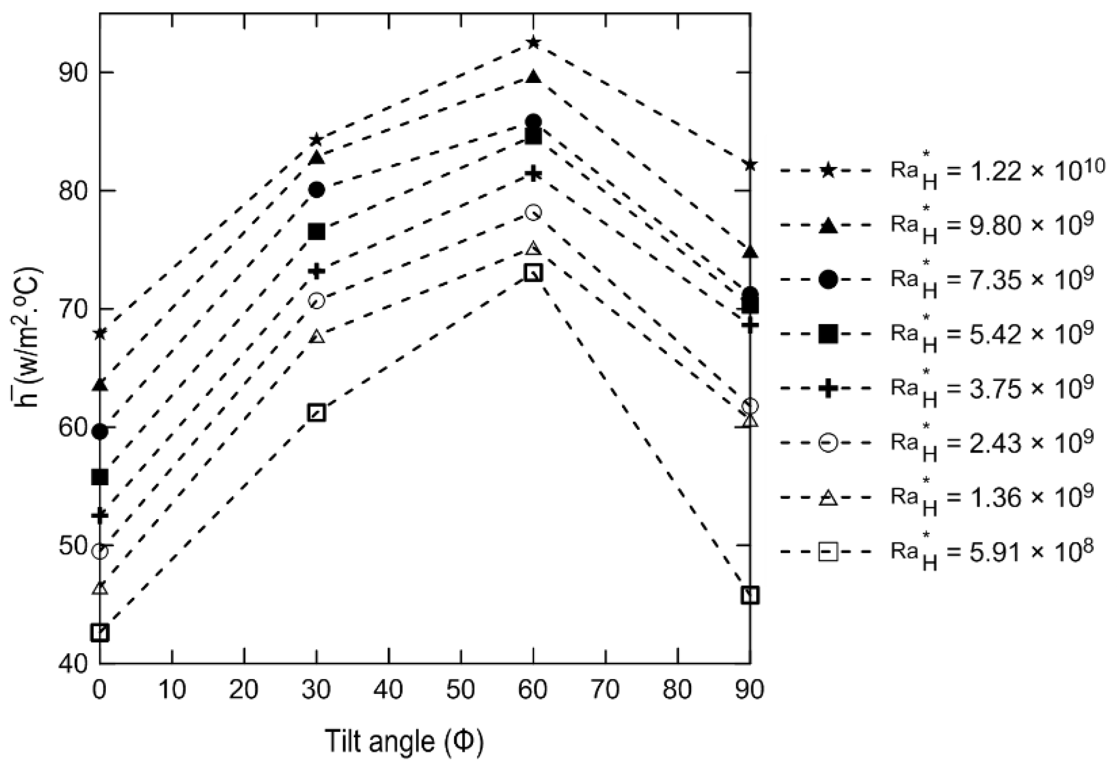
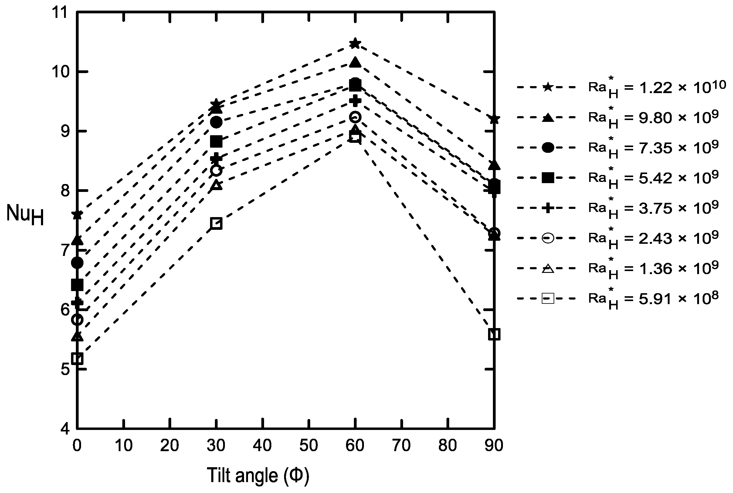
The variations in the heat transfer coefficients and Nusselt numbers as a function of the tilt angle for different are illustrated in Figure 7 and Figure 8, respectively. It was clear that by increasing the tilt angle, the heat transfer rate increased due to the developing buoyancy force and its effect on the velocity of the fluid and the developed vortices. The heat transfer coefficient and Nusselt numbers increased as φ increased, and they reached their maximum at 60° and then decreased again at 90°. The changes in the natural convection heat transfer coefficient and Nusselt numbers can be physically interpreted as described numerically by many investigators [31,32,33,34,35], who showed numerical streamlines and isothermal lines. Those flow patterns indicated that for a horizontal cavity, the flow was dominated by two counter circulating cells (i.e., Rayleigh–Bénard cells) within the cavity. Indeed, the fluid moved in the middle of the cavity from the hot bottom surface towards the cold top surface and then fell away on the sides of the cavity being pushed by the continually rising flow. As the tilt angle increased to , the fluid ascended near the right side surface and fell near the left sidewall, creating a single anticlockwise circulating cell direction. It was shown that one vortex cell increased the induced velocity better than the two developed vortices in the case of the horizontal enclosure. This led to an increase in both and, hence, in the Nu as indicated experimentally in Figure 7 and Figure 8. This increase continued up to a maximum angle of 60°, and then it reduced again at 90°, which could be attributed to a change in the flow field inside the enclosure to a boundary layer-type flow. Therefore, the experimental data shown in Figure 7 and Figure 8 agree physically well with those of the numerical investigations [31,32,33,34,35]. It should be noted that the average heat transfer coefficient and Nusselt number profiles shown in Figure 7 and Figure 8 are drawn as dashed lines, which means that these profiles were not a continuous function of the tilt angles, and more tilt angle experiments should be conducted to confirm the continuity of the functions. Furthermore, similar trends were obtained using 3D numerical computation by Sert et al. [36], who studied inclined cubical cavities with rectangular pins attached to the hot wall. In their study, the total Nusselt number was found to increase with the Rayleigh number and also to increase with the inclination angle up to a specific angle and then decrease, which agrees with the general trend in Figure 8. Moreover, three-dimensional natural convection in an inclined enclosure was reported by Ravnik et al. [37] using the boundary element method to study the natural convection phenomenon in cubic and parallelepipedal enclosures. They confirmed that the 2D approximation of the flow field was quite good, and the 2D calculated Nusselt number values were quite close (within 8%) to the Nusselt number values obtained with a 3D simulation. Therefore, in spite of the fact that most of the numerical studies were two-dimensional, most of the scientific physical interpretation as shown above is still valid, since the difference in Nusselt numbers was only within 8% [37], which agrees with the conclusion drawn above in discussing Figure 8. Furthermore, to capture the full development of the cell in 3D, the enclosure should have been made of visible surfaces and using proper visualization techniques.
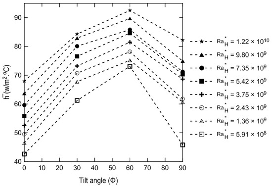
Figure 7.
Heat transfer coefficient versus tilt angle for different .

Figure 8.
Nusselt numbers versus tilt angle for different .
The enhancement percent of the Nusselt numbers is displayed in Table 3 at various tilt angles compared to that of the horizontal case using Equation (16):
Table 3.
The percentage of enhancement in the Nusselt numbers at different tilt angles compared to the horizontal enclosure according to Equation (16).
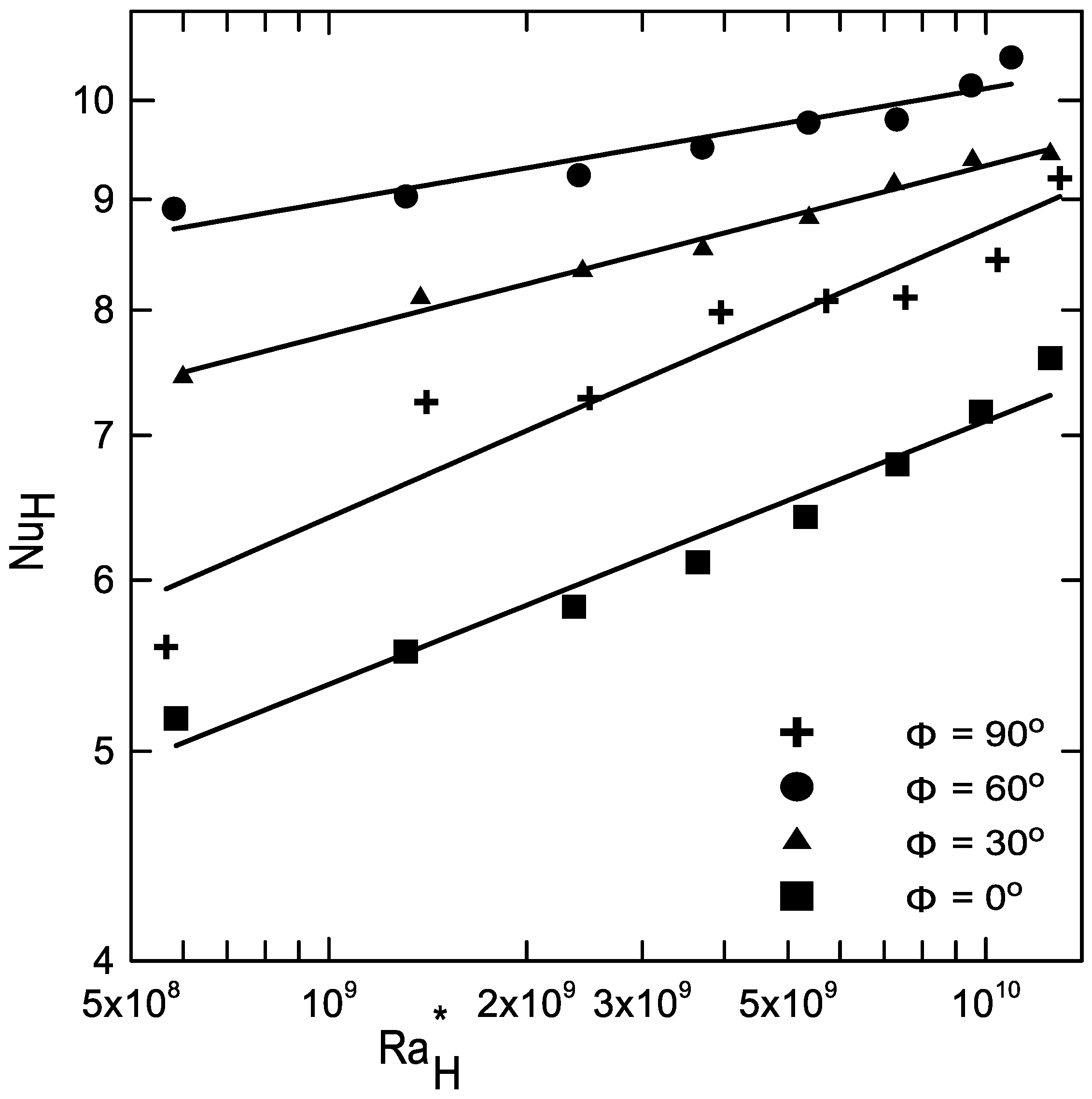
The experimental data points of the Nusselt numbers at different tilt angles versus are shown in Figure 9. It is clear that the Nusselt numbers had lower values for the horizontal case as described earlier.
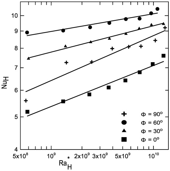
Figure 9.
Nu versus for different inclinations. Fitting correlations are presented by solid lines.
Fitting curves for the experimental data at each tilt angle are shown as solid lines in Figure 9. The empirical power law correlations were obtained in the form:
Table 4 shows the correlation constants, a, b and R2 (the coefficient of determination), at each tilt angle.
Table 4.
Correlation data used for correlation (13) at different tilt angles.
The modified Rayleigh number ( and the tilt angle (φ) were used as parameters in developing a general correlation for all angles (φ) as shown in Equation (18):
Table 5 shows the correlation constants, c–k, for Equation (18).
Table 5.
Correlation data used for correlation (18).
Another short correlation using trigonometric functions of the tilt angle and the modified Rayleigh numbers was obtained as:
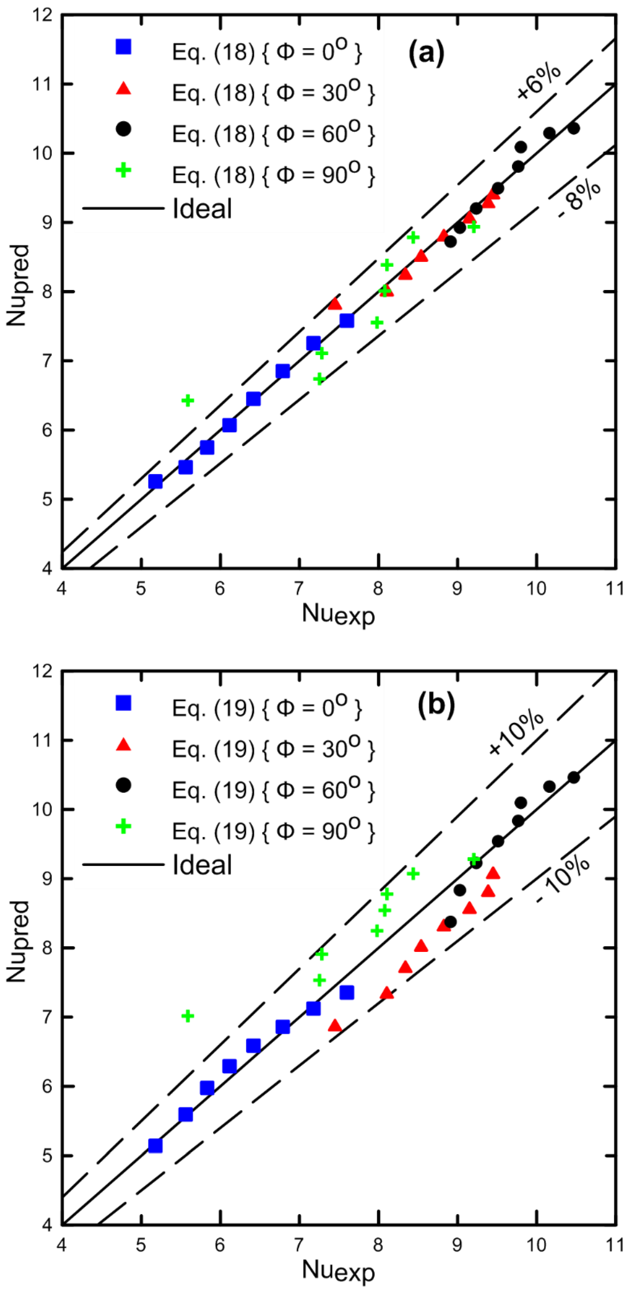
Correlation (19) gives the reader a quick overview of how the Nusselt number changes with both the Rayleigh number and the tilt angle; nevertheless, the coefficient of determination, R2, was higher for Equation (18) than for that of (19). The predicted and experimental Nusselt numbers for Equations (18) and (19) are plotted in Figure 10a,b for the cavity at all tilt angles: φ = 0°, φ = 30°, φ = 60°, and φ = 90°. The solid and dashed lines present the perfect fit and the error bandwidth, respectively. These band widths were +6% and −8% for Equation (18) and ±10% for Equation (19).
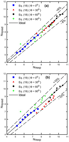
Figure 10.
(a,b) Comparison between the experimental data and the predicted values of Nu in the cavity for the four tilt angles: φ = 0°, φ = 30°, φ = 60°, and φ = 90°. The dashed lines present the difference bandwidths. (a) The correlation of Equation (18); (b) the correlation of Equation (19).
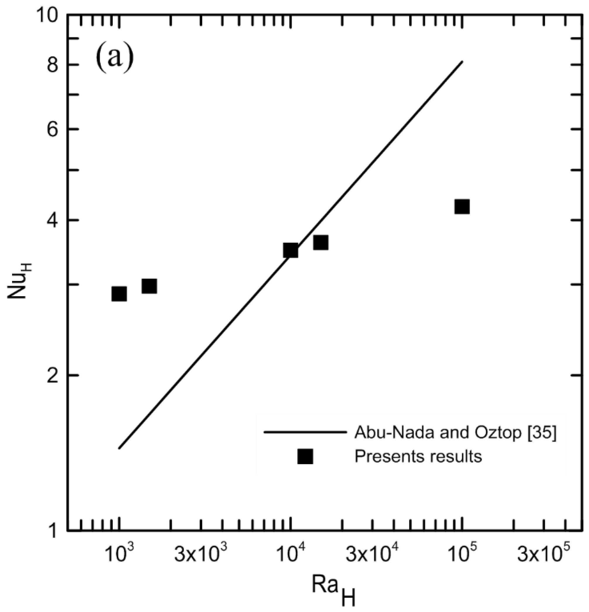
Figure 11 shows the Nusselt numbers and contour at various φ angles. It was clear that at a fixed , Nu increased as the tilt angle increased, until it reached a maximum at 60°. Furthermore, Nu always increased as increased at each φ. Figure 12a shows a comparison with [35] of the Rayleigh numbers and Nusselt number at a 30° angle; the solid line represents the results given by [35] for the 30° angle, and the square symbols represent the current experimental data points. It should be noted that the 2D numerical study by Abu-Nada et al. [35] was conducted at an aspect ratio equal to one. In the present study, however, the aspect ratio was equal to four; therefore, it was not a one-to-one comparison, but the comparison is presented to give a qualitive overview of with the current experimental data. It should also be noted that was converted to the Rayleigh number for the comparison to be consistent. Figure 12b displays another validation with the correlation obtained by Ali et al. [6] for an horizontal enclosure. There was a slight difference in the results as well due to the difference in the aspect ratio, which affected the values of the Nusselt numbers.
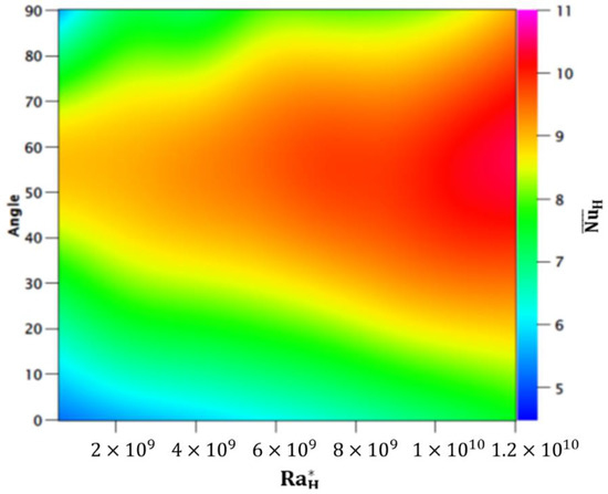
Figure 11.
Nu and contour at the four tilt angles of the cavity:.
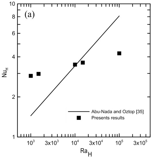
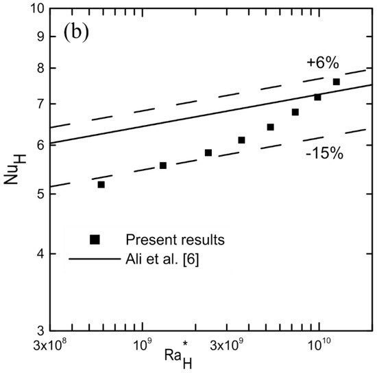
Figure 12.
Comparison with previous results: (a) with [35] at a 30° angle; (b) with [6] for a horizontal cavity (φ = 0°).
7. Conclusions
The effect of inclination angle on the development of free convection in a cavity was studied experimentally for a modified Rayleigh number range 5.89 × 10⁸–1.20 × 10¹⁰ and four different tilt angles:. The results indicate that the natural convection heat transfer inside the rectangular parallelepiped cavity was strongly dependent on both the tilt angle and . The average Nu increased as the inclination increased up to 60°, and then decreased at 90° for a fixed . This scenario was due to the buoyancy effect as discussed. The percent of enhancement in the Nusselt numbers at any tilt angle over that at zero tilt telt angle was obtained in the range of 7.92–62.38% depending on the modified Rayleigh numbers and the tilt angle (Table 3). Temperature contours at the hot and cold surfaces indicated that at low , the surfaces had uniform temperatures. However, as increased, this uniformity was disturbed. A correlation was obtained between Nu and for each tilt angle (Equation (17)). In addition, two more overall general correlations for all tilt angles () were obtained (Equations (18) and (19)) between the Nu and using the tilt angle as a parameter, which will be helpful for engineering applications. Comparison with previously published data indicates acceptable agreement with the current experimental data with some deviation due to the difference of used aspect ratio.
Author Contributions
Conceptualization, M.E.A. and K.A.-S.; methodology, R.A.; validation, R.A.; formal analysis, R.A.; Investigation, M.E.A., K.A.-S. and R.A.; resources, M.E.A. and K.A.-S.; data curation, R.A., K.A.-S. and M.E.A.; writing, R.A.; Review and editing, M.E.A. and K.A.-S.; supervision, M.E.A. and K.A.-S.; project administration, M.E.A. All authors have read and agreed to the published version of the manuscript.
Funding
The authors would like to extend their sincere appreciation to the Deanship of Scientific Research at King Saud University for funding this work through the Research Group Project No. (RGP-080).
Data Availability Statement
The data presented in this study are available on request from the corresponding author. The data are not publicly available due to [it is part of a Ph.D. thesis results, after the thesis defense it will be available.
Acknowledgments
The authors would like to extend their sincere appreciation to the Deanship of Scientific Research at King Saud University for funding this work through the Research Group Project No. RGP-080.
Conflicts of Interest
The authors declare no conflict of interest.
Nomenclature
| A | Enclosure surface area, m2 |
| Surface area of the Bakelite plate above the heater, m2 | |
| Surface area of the Bakelite sides, m2 | |
| H | Inside height of the cavity, m |
| h | Heat transfer coefficient, W m−2 k−1 |
| I | Electrical current, Ampere |
| k | Thermal conductivity, W m−2 k−1 |
| Nu | Nusselt number, h H/k |
| Qtotal | Input power electrical, W |
| Heat lost by conduction through the lower Bakelite plate, W | |
| Heat lost by conduction through the Bakelite sides, W | |
| Heat transfer by convection through the fluid, W | |
| R | Overall enclosure thermal resistances, K/W |
| Rss | Stainless-steel thermal resistances, K/W |
| Fluid thermal resistances, K/W | |
| Ra | |
| S | Inside length of the cavity, m |
| T | Temperature, °C |
| ∆T | , °C |
| U | Uncertainty |
| V | Voltage, volt |
| Greek symbols | |
| α | Thermal diffusivity, m−2 s−1 |
| β | Coefficient for thermal expansion, K−1 |
| δ | Bakelite thickness |
| ν | Kinematics viscosity, m−2 s−1 |
| Δx | Thickness of stainless steel, m |
| φ | Tilt angle of the cavity |
| Aspect ratio, | |
| Subscripts | |
| Bakelite plate | |
| Bks | Bakelite side |
| cs | Cold surface |
| exp | Experimental data |
| H | Characteristic length |
| hs | Hot surface |
| Inside Bakelite surface | |
| pred | Predicted data |
| ss | Stainless steel |
| Superscripts | |
| - | Averaged quantity |
References
- Ostrach, S. Natural Convection in Enclosures. J. Heat Transf. 1988, 110, 1175–1190. [Google Scholar] [CrossRef]
- Jeng, D.Z.; Yang, C.S.; Gau, C. Experimental and numerical study of transient natural convection due to mass transfer in inclined enclosures. Int. J. Heat Mass Transf. 2009, 52, 181–192. [Google Scholar] [CrossRef]
- Esfahani, J.A.; Alinejad, J. Entropy generation of conjugate natural convection in enclusures: The lattice Boltzmann method. J. Thermophys. Heat Transf. 2013, 27, 498–505. [Google Scholar] [CrossRef]
- Rasoul, J.; Prinos, P. Natural convection in an inclined enclosure. Int. J. Numer. Methods Heat Fluid Flow 1997, 7, 438–478. [Google Scholar] [CrossRef]
- Pandey, S.; Park, Y.G.; Ha, M.Y. An exhaustive review of studies on natural convection in enclosures with and without internal bodies of various shapes. Int. J. Heat Mass Transf. 2019, 138, 762–795. [Google Scholar] [CrossRef]
- Ali, M.E.-S.; Nuhait, A.O.; Alabdulkarem, A.; Almuzaiqer, R. Free convection heat transfer inside square water-filled shallow enclosures. PLoS ONE 2018, 13, e0204251. [Google Scholar] [CrossRef] [Green Version]
- Imberger, J. Natural convection in a shallow cavity with differentially heated end walls. Part 3. Experimental results. J. Fluid Mech. 1974, 65, 247–260. [Google Scholar] [CrossRef]
- Bejan, A.; Al-Homoud, A.A.; Imberger, J. Experimental study of high-Rayleigh-number convection in a horizontal cavity with different end temperatures. J. Fluid Mech. 1981, 109, 283–299. [Google Scholar] [CrossRef]
- Hiroyuki, O.; Akira, M.; Masaru, O.; Churchill, S.W.; Lior, N. Numerical calculations of laminar and turbulent natural convection in water in rectangular channels heated and cooled isothermally on the opposing vertical walls. Int. J. Heat Mass Transf. 1985, 28, 125–138. [Google Scholar] [CrossRef]
- Valencia, L.; Pallares, J.; Cuesta, I.; Grau, F.X. Turbulent Rayleigh–Bénard convection of water in cubical cavities: A numerical and experimental study. Int. J. Heat Mass Transf. 2007, 50, 3203–3215. [Google Scholar] [CrossRef]
- Mahdavi, M.; Sharifpur, M.; Ghodsinezhad, H.; Meyer, J.P. Experimental and numerical investigation on a water-filled cavity natural convection to find the proper thermal boundary conditions for simulations. Heat Transf. Eng. 2018, 39, 359–373. [Google Scholar] [CrossRef] [Green Version]
- Kuznetsov, G.V.; Sheremet, M.A. Conjugate natural convection with radiation in an enclosure. Int. J. Heat Mass Transf. 2009, 52, 2215–2223. [Google Scholar] [CrossRef]
- Ibrahim, A.; Saury, D.; Lemonnier, D. Coupling of turbulent natural convection with radiation in an air-filled differentially-heated cavity at Ra = 1.5 × 10⁹. Comput. Fluids 2013, 88, 115–125. [Google Scholar] [CrossRef]
- Salat, J.; Xin, S.; Joubert, P.; Sergent, A.; Penot, F.; Le Quere, P. Experimental and numerical investigation of turbulent natural convection in a large air-filled cavity. Int. J. Heat Fluid Flow 2004, 25, 824–832. [Google Scholar] [CrossRef]
- Kuyper, R.; Van Der Meer, T.H.; Hoogendoorn, C.; Henkes, R. Numerical study of laminar and turbulent natural convection in an inclined square cavity. Int. J. Heat Mass Transf. 1993, 36, 2899–2911. [Google Scholar] [CrossRef]
- Markatos, N.C.; Pericleous, K. Laminar and turbulent natural convection in an enclosed cavity. Int. J. Heat Mass Transf. 1984, 27, 755–772. [Google Scholar] [CrossRef]
- Ampofo, F.; Karayiannis, T. Experimental benchmark data for turbulent natural convection in an air filled square cavity. Int. J. Heat Mass Transf. 2003, 46, 3551–3572. [Google Scholar] [CrossRef]
- Kim, D.; Viskanta, R. Study of the effects of wall conductance on natural convection in differently oriented square cavities. J. Fluid Mech. 1984, 144, 153–176. [Google Scholar] [CrossRef]
- Saglam, M.; Sarper, B.; Aydin, O. Natural Convection in an Enclosure with a Pair of Discrete Heat Sources. J. Thermophys. Heat Transf. 2019, 33, 234–245. [Google Scholar] [CrossRef]
- Bahoosh, R.; Mohamadi, F.; Karimi, M. Numerical investigation of natural convection in a square cavity with tilting walls. J. Thermophys. Heat Transf. 2015, 29, 725–731. [Google Scholar] [CrossRef]
- Hasnaoui, M.; Bilgen, E.; Vasseur, P. Natural convection heat transfer in rectangular cavities partially heated from below. J. Thermophys. Heat Transf. 1992, 6, 255–264. [Google Scholar] [CrossRef]
- Varol, Y.; Oztop, H.F.; Koca, A.; Avci, E. Forecasting of entropy production due to buoyant convection using support vector machines (SVM) in a partially cooled square cross-sectional room. Expert Syst. Appl. 2009, 36, 5813–5821. [Google Scholar] [CrossRef]
- Deng, Q.-H. Fluid flow and heat transfer characteristics of natural convection in square cavities due to discrete source–sink pairs. Int. J. Heat Mass Transf. 2008, 51, 5949–5957. [Google Scholar] [CrossRef]
- Corcione, M. Effects of the thermal boundary conditions at the sidewalls upon natural convection in rectangular enclosures heated from below and cooled from above. Int. J. Therm. Sci. 2003, 42, 199–208. [Google Scholar] [CrossRef]
- Calcagni, B.; Marsili, F.; Paroncini, M. Natural convective heat transfer in square enclosures heated from below. Appl. Therm. Eng. 2005, 25, 2522–2531. [Google Scholar] [CrossRef]
- Callister, W.D.; Rethwisch, D.G. Materials Science and Engineering; John Wiley & Sons NY: Hoboken, NJ, USA, 2011; Volume 5. [Google Scholar]
- Siegel, R.; Howell, J. Thermal Radiation Heat Transfer; Mcgraw-Hill Inc.: New York, NY, USA, 1980. [Google Scholar]
- Bejan, A. Convection Heat Transfer; John Wiley & Sons: Hoboken, NJ, USA, 2013. [Google Scholar]
- Klein, S.A.; Alvarado, F. Engineering Equation Solver (EES); FChart Software: Madison, WI, USA, 2011. [Google Scholar]
- Taylor, B.N.; Kuyatt, C.E. NIST technical note 1297. In Guidelines for Evaluating and Expressing the Uncertainty of NIST Measurement Results; United States Department of Commerce Technology Administration: Washington, DC, USA, 1994; Volume 1, pp. 14571–14577. [Google Scholar]
- Rahman, M.; Sharif, M. Numerical study of laminar natural convection in inclined rectangular enclosures of various aspect ratios. Numer. Heat Transf. Part A Appl. 2003, 44, 355–373. [Google Scholar] [CrossRef]
- Ghasemi, B.; Aminossadati, S. Natural convection heat transfer in an inclined enclosure filled with a water-CuO nanofluid. Numer. Heat Transf. Part A Appl. 2009, 55, 807–823. [Google Scholar] [CrossRef]
- Hussain, S.H.; Hussein, A.K.; Mahdi, M.M. Natural convection in a square inclined enclosure with vee-corrugated sidewalls subjected to constant flux heating from below. Nonlinear Anal. Model. Control 2011, 16, 152–169. [Google Scholar] [CrossRef] [Green Version]
- Inam, M.I. Direct Numerical Simulation of Laminar Natural Convection in a Square Cavity at Different Inclination Angle. J. Eng. Adv. 2020, 1, 23–27. [Google Scholar] [CrossRef]
- Abu-Nada, E.; Oztop, H.F. Effects of inclination angle on natural convection in enclosures filled with Cu–water nanofluid. Int. J. Heat Fluid Flow 2009, 30, 669–678. [Google Scholar] [CrossRef]
- Sert, Z.; Tekkalmaz, M.; Timuralp, C. Combined natural convection and thermal radiation in an inclined cubical cavity with a rectangular pins attached to its active wall. Period. Eng. Nat. Sci. 2017, 5, 347–354. [Google Scholar] [CrossRef] [Green Version]
- Ravnik, J.; Škerget, L.; Žunič, Z. Velocity–vorticity formulation for 3D natural convection in an inclined enclosure by BEM. Int. J. Heat Mass Transf. 2008, 51, 4517–4527. [Google Scholar] [CrossRef]


Publisher’s Note: MDPI stays neutral with regard to jurisdictional claims in published maps and institutional affiliations. |
© 2022 by the authors. Licensee MDPI, Basel, Switzerland. This article is an open access article distributed under the terms and conditions of the Creative Commons Attribution (CC BY) license (https://creativecommons.org/licenses/by/4.0/).