Article

Experimental and Numerical Validation of the One-Process Modeling Approach for the Hydration of K2CO3 Particles

1
Department of Mechanical Engineering, Eindhoven University of Technology, P.O. Box 513, 5600 MB Eindhoven, The Netherlands
2
Cellcius, Horsten 1, 5612 AX Eindhoven, The Netherlands
*
Author to whom correspondence should be addressed.
Processes 2022, 10(3), 547; https://doi.org/10.3390/pr10030547
Submission received: 21 January 2022 / Revised: 27 February 2022 / Accepted: 8 March 2022 / Published: 11 March 2022
(This article belongs to the Special Issue Advances in Thermochemical Energy Storage)

Abstract

:
Potassium carbonate (K 2 CO 3 ) is a promising material for the long-term storage of renewable energy. A reactor vessel filled with K 2 CO 3 can potentially be used as a domestic heat battery. The hydration and dehydration reactions of salt hydrates in a reactor vessel are generally described using a one-process model, such as the ‘Arrhenius- f ( α ) ’ model. However, this modeling approach cannot always be applied correctly. If the reaction does not proceed in a pseudo-steady state, and/or when nucleation and growth processes are simultaneously active during the transformation from an anhydrous to a hydrated state, the one-process modeling approach should not be applied. In this paper, it is investigated using simultaneous thermal analysis (STA) experiments whether the pseudo-steady state approximation is valid during the hydration reaction of K 2 CO 3 . Additionally, ‘jump experiments’ using STA are employed to investigate the rate-determining step (RDS) of the hydration reaction by applying step-wise changes in partial water vapor pressure. The presence of nucleation and growth processes during the hydration reaction is investigated by fitting isotropic models to STA data. The STA results showed that indeed the hydration of K 2 CO 3 happens in a pseudo-steady state, and the reaction can be described using a RDS. An isotropic nucleation and growth model shows that the hydration reaction can be described by assuming instantaneous nucleation followed by diffusion-limited growth. This leads to the general conclusion that the one-process modeling approach, such as the Arrhenius- f ( α ) model, is valid to describe the hydration reaction of K 2 CO 3 particles.

1. Introduction

Fossil fuel depletion and climate change are becoming increasingly hot topics in Europe. A large number of countries signed the Paris Agreement in 2015 [1], dedicating themselves to restraining greenhouse gas emissions. Renewable energy sources are to be promoted to limit the global temperature rise below 2 degrees Celsius compared to pre-industrial levels. A total of 20% of the final energy consumption is used in the residential sector [2]; 66% of this energy consumption was used for space and water heating in 2017. Since the domestic heating demand is largely met by fossil-fuel-powered boilers, it is evident that a large reduction in emissions can be gained by introducing renewables in the residential sector. Popular renewable energy sources, such as solar and wind energy, are intermittent, which results in a mismatch in supply and demand. Thermal energy storage is one solution to the supply and demand mismatch. Excess solar thermal energy produced during sunny periods can be used to charge a so-called heat battery. Discharging the battery when the demand is high can provide the thermal energy required for the residential sector [3]. Thermal energy storage in thermochemical materials (TCMs) is a promising technique to store thermal energy in a compact and quasi loss-free way. TCM systems can be charged by adding thermal energy collected by, for example, solar thermal panels. This energy initiates an endothermal dissociation reaction and separates the sorbent (dry TCM) and the sorbate (often water vapor). Keeping the sorbent and sorbate separate allows thermal energy to be stored for a prolonged time since the energy is not stored in sensible or latent form, but as a chemical potential. Recombining sorbent and sorbate triggers the exothermal discharge reaction and discharges the stored energy. For low temperature sorption thermal energy storage systems, a distinction between adsorption (e.g., zeolites [4]) and absorption (e.g., salt hydrates [5,6]) is made. Adsorption is used to describe the binding of a gas on the surface of a solid or porous material. Absorption can be defined as a phenomenon in which a liquid or gas penetrates the surface layer and enters a solid or liquid [7]. While both adsorption and absorption TCMs can be used for the creation of a heat battery, in terms of theoretical energy density, salt hydrates are more promising compared to zeolites [8]. In the work of Donkers et al. [6], 563 reactions were evaluated based on criteria such as hydration temperature, dehydration temperature, energy density, safety and costs. Their study concluded that potassium carbonate (K 2 CO 3 ) is one of the best candidates for thermal energy storage applications.
K 2 CO 3 is reported to be chemically robust [9]. Charging and discharging 1 m 3 of the material 12–52 times (monthly to weekly) yields a yearly base energy of 15–65 GJ. This makes the material a good candidate for a domestic heat battery. Because of its chemical robustness and high potential to be used in a heat battery, K 2 CO 3 is studied in this paper. The hydration and dehydration reaction of K 2 CO 3 is described by
K 2 CO 3 ( s ) + 1.5 H 2 O ( g ) K 2 CO 3 · 1.5 H 2 O ( s ) + Δ H R ,
where Δ H R is the reaction enthalpy, which is equal to 65.8 kJ/mol [6,10]. The literature suggests only two stable hydration states, namely anhydrate (no H 2 O) and sesquihydrate (1.5 H 2 O) [6,9,11,12,13].
A numerical model that describes the reaction rates of a heat battery is required for proper design and optimization purposes. An in-depth understanding of the local reaction rate inside the reactor is of major importance. The reaction rate of the material in the reactor vessel depends on the sorption material, the local temperature, the local concentration, and the state of charge [14,15]. The power output of the thermal battery containing K 2 CO 3 can be maximized by hydrating the material at temperatures and partial water pressures close to the deliquescence conditions. These conditions are displayed in the phase diagram of K 2 CO 3 [16]. The hydration rate is maximized at these conditions and therefore also the thermal power output of a K 2 CO 3 heat battery. The hydration reaction rate of sorption particles can become limited if insufficient water vapor is transported to the particles [16]. This can become an issue when water vapor has to diffuse through multiple particle layers. To study the hydration on the particle level, effort should be made to ensure that water vapor transport to the sorption particles is not limiting the hydration rate.
Often, the so-called ‘Arrhenius- f ( α ) ’ model is employed to describe the reaction rate of a salt hydrate. This modeling approach is generally assumed to be valid to describe the rate reaction of salt hydrates. The limitations of the Arrhenius- f ( α ) models are elaborated in the work of Pijolat et al. [17]. They describe an experimental method to determine if the Arrhenius- f ( α ) modeling approach is valid to describe solid–gas reactions (e.g., salt hydrates) [18,19]. The models and experimental methods described by Pijolat et al. were applied successfully in the literature and led to a greater understanding of different reactions [20,21,22,23,24,25,26]. However, these models and experimental methods have not yet been employed to study K 2 CO 3 .
This work aims to investigate if the hydration of K 2 CO 3 as thermal energy storage material can be described using the Arrhenius- f ( α ) model on particle level. To do so, it is important to exclude the influence of vapor transport to the particle. First, Section 2 provides background information about the elementary steps, nucleation and growth processes and solid–gas reaction models. Section 2.1 and Section 2.2 explain the pseudo-steady state approximation and nucleation and nuclei growth, respectively. In Section 2.3, the commonly used ‘Arrhenius- f ( α ) ’ modeling approach is explained, and its limitations are discussed. In particular, three important requirements for the correct usage of the ‘Arrhenius- f ( α ) ’ equation are given. Section 2.4 explains the one-process and two-process models and their relation to the ‘Arrhenius- f ( α ) ’ equation. The materials and experimental methods are explained in Section 3. The hydration reaction of K 2 CO 3 is studied using TGA/DSC experiments. Different hydration-limiting mass transport phenomena, such as water vapor transport to the K 2 CO 3 particles and diffusion of water vapor through hydrated K 2 CO 3 are investigated in Section 4. Finally, it is checked whether the hydration reaction of K 2 CO 3 can be described by a one-process modeling approach, and whether the ‘Arrhenius- f ( α ) ’ equation can be applied to the hydration of K 2 CO 3 .

2. Theoretical Background

2.1. Elementary Steps

The hydration and dehydration reaction of K 2 CO 3 as described in Equation (1) is the result of one or more intermediate reactions called ‘elementary steps’. Intermediates are created and consumed during these elementary steps but are not shown in the overall reaction. If the generation of intermediates is larger than the consumption of intermediates, there is a net buildup of intermediate species. If a reaction has a significant buildup of intermediates, multiple elementary steps are affecting the overall reaction at the same time. This requires multiple elementary steps to be taken into account when describing the overall reaction [24]. If there is no net buildup of intermediate species, a heterogeneous reaction is said to be in a pseudo-steady state, and only one elementary step limits the overall reaction. If only one elementary step is determining the overall reaction rate, the reaction can be described using the rate-determining step (RDS) for this elementary step. The reaction mechanism is the sequence of elementary steps that are required to go from reactant to product. Two types of mechanisms exist for hydration and dehydration reactions; mechanisms for nucleation, and mechanisms for nuclei growth.

2.2. Nucleation and Nuclei Growth

Nucleation and growth processes are present during the hydration reaction of K 2 CO 3 [27]. Nucleation is the initiation of the reactant–product interface, and involves the transformation of a small amount of a reactant (here: anhydrous K 2 CO 3 ) into a stable product (K 2 CO 3 sesquihydrate) [28]. Here, nucleation is defined as the spontaneous formation of a stable nucleus, which is defined as an aggregate grown to a critical size [29]. A nucleation mechanism can be depicted by a series of elementary steps, such as defect formation, their migration across the surface of the solid, and finally the aggregation of defects leading to a stable nucleus [24]. An example of defect formation is the addition or removal of a water molecule from the crystal structure in the case of a hydration or dehydration reaction. The size of a stable nucleus depends on the temperature and partial vapor pressure. The nucleation process is expected to only occur on the surface of the solid [17,24]. The nucleation rate depends on the total area that has not reacted yet and the thermodynamic conditions such as temperature and pressure. Additionally, the mechanism for the nucleation of solid–gas reactions can also depend on the surface characteristics of the solid, such as roughness, edges, and peaks [17,21,24]. Once a stable nucleus has formed, it can start to grow. The interface advance of the reactant into product following nucleation is called nuclei growth. Elementary steps of growth are, for example, surface gas adsorption or desorption, internal interface reaction and diffusion through the product layer. Nahdi et al. [23] found that the growth rate depends differently on temperature and pressure than the nucleation rate. This suggests that nucleation and growth are separate mechanisms.

2.3. Solid–Gas Reaction Models

Models describing the reaction rate of salt hydrates have been established and described in literature, and are often of the following form:
d α d t = k ( T ) f ( α ) h ( P ) ,
where k ( T ) is the Arrhenius term [s 1 ], f ( α ) is a reaction model term [-], and h ( P ) is a pressure term [-] [11,15,30]. f ( α ) is a mathematical function depending on the kind of transformation model (e.g., shrinking core—R3, diffusion—D3, first order—F1, etc.) [31,32]. The conversion α of a salt hydrate is defined as the extent of hydration or dehydration in terms of mass, and its value lies between 0 and 1. The conversion of K 2 CO 3 based on mass difference is given by
α m ( t ) = m ( t ) m 0 m m 0 ,
in which m ( t ) is the mass [mg] of the sample at time t, the dehydrated sample mass is equal to m 0 [mg], and the fully hydrated sample mass is equal to m [mg]. The conversion can also be based on the amount of heat released (Q) during the hydration, and is given by
α Q ( t ) = Q ( t ) Δ H R n 0 .
Δ H R represents the reaction enthalpy for the hydration of potassium carbonate. n 0 is the number of moles of K 2 CO 3 . Both α m and α Q range between 0 and 1.
The Arrhenius- f ( α ) modeling approach is recommended by the ICTAC Kinetics Committee [30] and employed frequently in the literature to model solid–gas reactions [11,15,33]. The rate constant is a function of temperature according to the Arrhenius equation:
k ( T ) = A · exp E a R T
where A is the pre-exponential factor [s 1 ], E a is the apparent activation energy [J mol 1 ], R is the gas constant [J mol 1 K 1 ] and T is the temperature [K]. E a and A can be determined using isoconversional methods [30,34,35]. The Arrhenius- f ( α ) model comes with some limitations: it cannot take into account simultaneous nucleation and growth processes [17], while generally, solid–gas reactions consist of both nucleation and growth processes. Furthermore, the Arrhenius- f ( α ) model does not shed any light on the influence of morphologic variables, as these are lumped in the pre-exponential factor A. In the literature, a pressure ratio term is added to the Arrhenius- f ( α ) model to account for the anhydrous-hydrated equilibrium pressure, and the partial water vapor pressure [30,33,36,37,38]. The pressure term is given by
h ( P ) = 1 P e q P w v ,
where P e q is the equilibrium pressure [mbar] and P w v is the water vapor pressure [mbar] measured or applied during an experiment. The anhydrous-hydrated equilibrium pressure P e q is calculated using the Clausius–Clapeyron equation.
To describe solid–gas reactions, Equation (2) only holds if three conditions are met:
(1)
There should be no accumulation of intermediate species; the reaction is in a pseudo-steady state [17].
(2)
The reaction is a single-step reaction [17,18]. In other words, there should be one elementary step that is rate-determining and controlling the reaction from α = 0 to α = 1. The activation energy E a should not vary with changing α , as this would suggest a multi-step reaction.
(3)
The reaction can be described using a one-process model. This means that either nucleation or growth can be considered instantaneous during the reaction [17,18,22,39].
It is of major importance to investigate if the three mentioned conditions are met before the Arrhenius- f ( α ) equation can be applied to correctly describe the hydration or dehydration of salt hydrates.
Pijolat et al. [17] suggest a more generalized approach to describe the reaction rate. Their proposed ‘separation model’ can be applied to model gas–solid reactions regardless of morphological characteristics or the type of reaction. These separation models do not require k ( T ) to depend on temperature according to the Arrhenius equation, or require the dependence of f ( α ) on α . Separation models are successfully applied to describe different heterogeneous reactions [20,22,23,24,25,40]. The separation models consist of two separate functions and hold if the pseudo-steady state approximation and the single-step reaction conditions are met. The conversion rate of the separation model is described by [14,17]
d α d t = ϕ ( T , P ) S m ( t , ) ,
where ϕ ( T , P ) is the ‘areic growth rate’ [mol m 2 s 1 ], S m ( t , ) is the so-called ‘space function’ [m 2 mol 1 ] and t is the time [s]. Equation (7) allows the separation of thermodynamic and morphological variables. The areic growth rate ϕ ( T , P ) takes into account the dependency of the conversion rate on thermodynamic variables, such as temperature and pressure [24]. ϕ ( T , P ) does not depend on the morphological variables. The space function S m ( t , ) takes into account the morphological variables. It describes the ‘molar active surface area’ at which the reaction takes place [14,24].

2.4. One-Process and Two-Process Models

Generally, two families of models can be distinguished: one-process models and two-process models. One-process models are employed when either nucleation or nuclei growth happens so fast it can be considered instantaneous after the reaction starts. Instantaneous nuclei growth is a rather uncommon process and therefore, only instantaneous nucleation is taken into account for the hydration of K 2 CO 3 . When the nucleation rate is extremely high, the particles are instantly covered with a very thin (negligibly small) layer of product. An example of a one-process model with instantaneous nucleation limited by growth is the diffusion (D3) model. The reaction rate for spherical particles and adopting the notation used in Pijolat et al. and Favergeon et al. [24,41] can be rewritten as
d α d t = ϕ ( T , P ) S m ( t , ) = ϕ ( T , P ) V m A r 0 f ( α ) = ϕ ( T , P ) V m A r 0 3 ( 1 α ( t ) ) 2 / 3 2 ( 1 ( 1 α ( t ) ) 1 / 3 ,
where V m A is the molar volume of a dry solid reactant (e.g., anhydrous K 2 CO 3 in the case of a hydration reaction) [m 3 mol 1 ], r 0 is the particle radius [m] and f ( α ) is the D3 model obtained from the literature [32].
If the hydration reaction proceeds in a pseudo-steady state, has a RDS during the complete reaction and proceeds according to a one-process model, the Arrhenius- f ( α ) modeling approach (Equation (2)) can also be applied to correctly describe the hydration reaction [24].
A two-process model describes both nucleation and growth, simultaneously. If a reaction as a function of time has a sigmoidal shape, it is a strong indication that both nucleation and growth processes are simultaneously active [21]. In the case of two-process models, the nucleation process is not instantaneous. The nucleation rate may depend strongly on temperature and partial pressure. The total reaction rate is a function of both the rate at which nuclei appear on the surface of the material and the growth rate of each one of these nuclei. The kinetic rate when both nucleation and growth processes are simultaneously active can be described by [17,24]
d α d t = 0 t γ ( T , P ) S L ( τ ) ϕ ( T , P ) s m ( t , τ ) d τ ,
where τ is the birth time of a nucleus [s], and γ is the areic rate of nucleation [nuclei m 2 s 1 ]. Nuclei born at time τ , τ < t, are formed on the material surface with frequency γ ( T , P ) S L ( τ ) [nuclei s 1 ]. S L ( τ ) is the remaining unreacted particle area available for nucleation [m 2 ] at time τ . The ‘history’ of the reaction should be considered when calculating S m . For this reason S m cannot be written as a function of α , and therefore, for two-process models, Equation (2) cannot be used to describe the reaction rate [17,24]. In the following sections, it is investigated whether K 2 CO 3 should be modeled by a one-process or a two-process model. This is done experimentally by employing the ‘ f ( α ) -test’ (Section 4.3.2) and numerically by using two-process models (Section 4.4.2) to fit experimental hydration conversion data.

3. Materials and Experimental Methods

3.1. Sample Preparation

Previous multi-cyclic studies on K 2 CO 3 particles showed that the hydration reaction rate strongly depends on the number of charge- and discharge cycles [42]. This cycle dependency was attributed to changes in particle morphology, such as crack formation and particle volume growth. To exclude the cycling effect on the hydration reaction rate, a large batch of dry K 2 CO 3 particles was created. For each experiment, a small sample was taken from this large batch. The particles consist of mechanically pulverized K 2 CO 3 particles (Sigma-Aldrich). The pulverization was done in a grinding machine. The machine uses spherical grind stones to grind down the K 2 CO 3 particles from 700–1000 μ m in diameter to 25–38 μ m in diameter after sieving. SEM images of the K 2 CO 3 particles are displayed in Figure 1a,b.
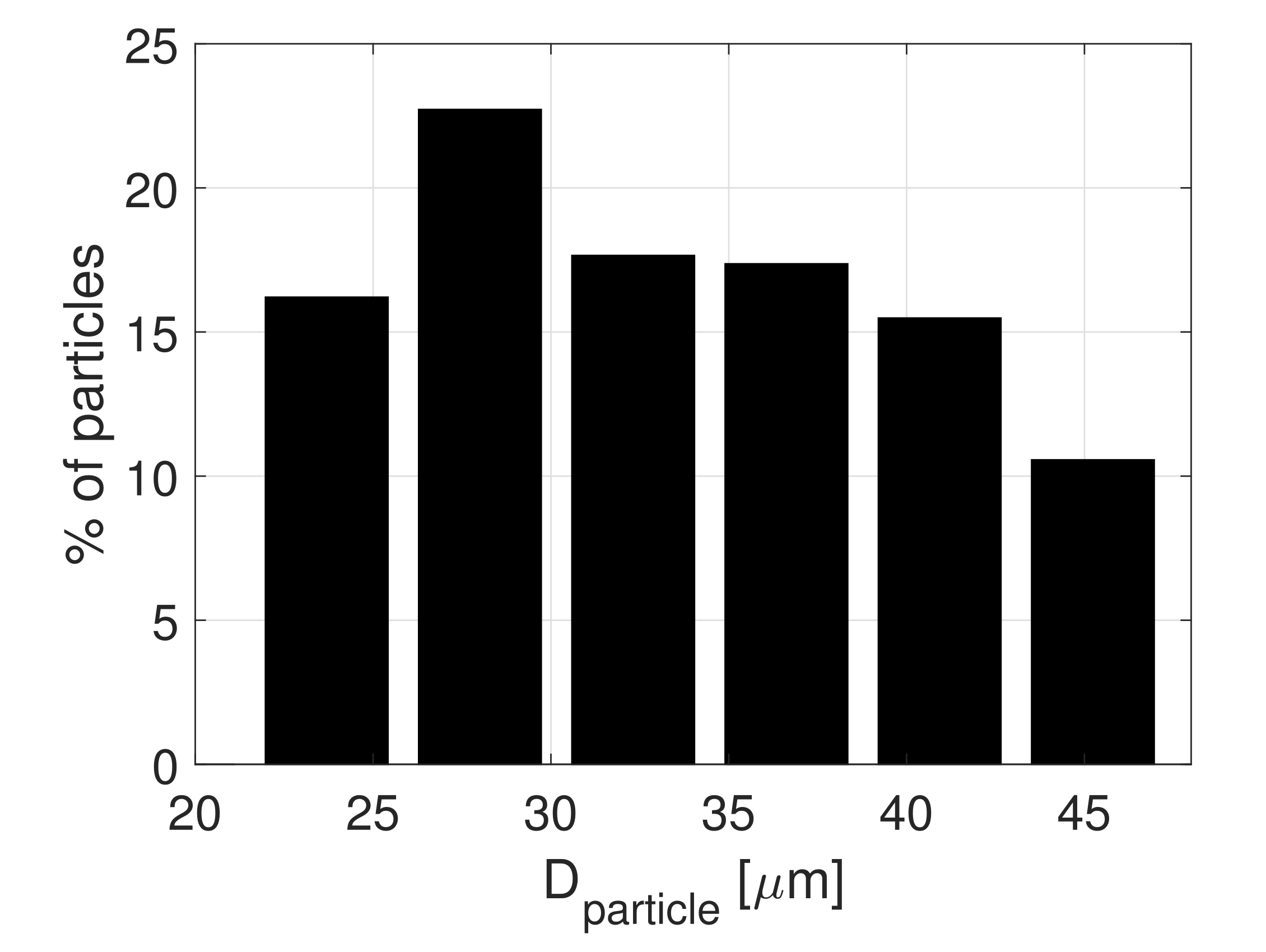
It is observed that the particles are agglomerates of multiple tiny crystals, despite being pulverized. Information on the particle size distribution was obtained using optical microscopy. A dry, uncycled sample was taken from the large batch and analyzed in a micro-climate chamber (Linkam THMS-600 Stage) with a Zeiss SteREO Discovery V20 microscope. The humidity in the micro-climate chamber was set to 0% RH and the temperature to 60 C to prevent hydration. Pictures were taken with the microscope and processed using MATLAB’s image toolbox. A total of 575 particles were analyzed. From Figure 1a, it can be concluded that most of the particles have a spherical shape. This is not always clearly visible, as particles are stacked on top of each other. In this study, it is assumed for the modeling that the particles are perfect spheres.
The particle diameter is calculated using D p a r t i c l e = 4 A p a r t i c l e / π , where A p a r t i c l e is the projected surface area of the particle determined by the microscope. The particle size distribution is shown in Figure 2. It is observed that the batch is comprised of an approximately uniform distribution within the range of 22–46 μ m in diameter.
According to Figure 2, some particles have a diameter larger than 38 μ m, which is larger than the sieve size. This is because some particles are not spherical but, for example, elliptical in shape. Those particles are able to pass through the 38 μ m sieve mesh if the minor diameter of the ellipse is smaller than 38 μ m, even if the major diameter is larger than 38 μ m.

3.2. STA Experiments

The hydration reaction rates of K 2 CO 3 are measured using a simultaneous thermal analysis (STA) device (Netzsch STA 449 F3 Jupiter). An STA measurement is done using two crucibles placed on top of a very sensitive balance. One crucible is filled with the sample and one remains empty as a reference. Aluminum crucibles without a lid with a mass of approximately 26 mg, a diameter of 6 mm and a height of 3 mm are used. Both crucibles are close to each other and, therefore, exposed to the same environmental conditions, such as temperature and partial water pressure. The mass change of the sample due to water absorption is measured, using thermogravimetric analysis (TGA). The thermal energy released by the sample due to moist absorption is measured by differential scanning calorimetry (DSC). Small thermocouples below the aluminum crucibles register the temperature of both the empty reference and the sample crucible. A temperature difference between the two crucibles is caused by the exothermic hydration reaction of K 2 CO 3 . Both crucibles are surrounded by a temperature-controlled copper furnace with an accuracy of ±0.1 K. This allows one to heat the sample.
The sample can be actively cooled by a separate heat exchanger connected to a vortex cooler. The vortex cooler generates cool air by expanding pressurized air at 7 bars. This air flows through the heat exchanger tubes surrounding both crucibles. The crucibles are not in direct contact with this cooling stream.
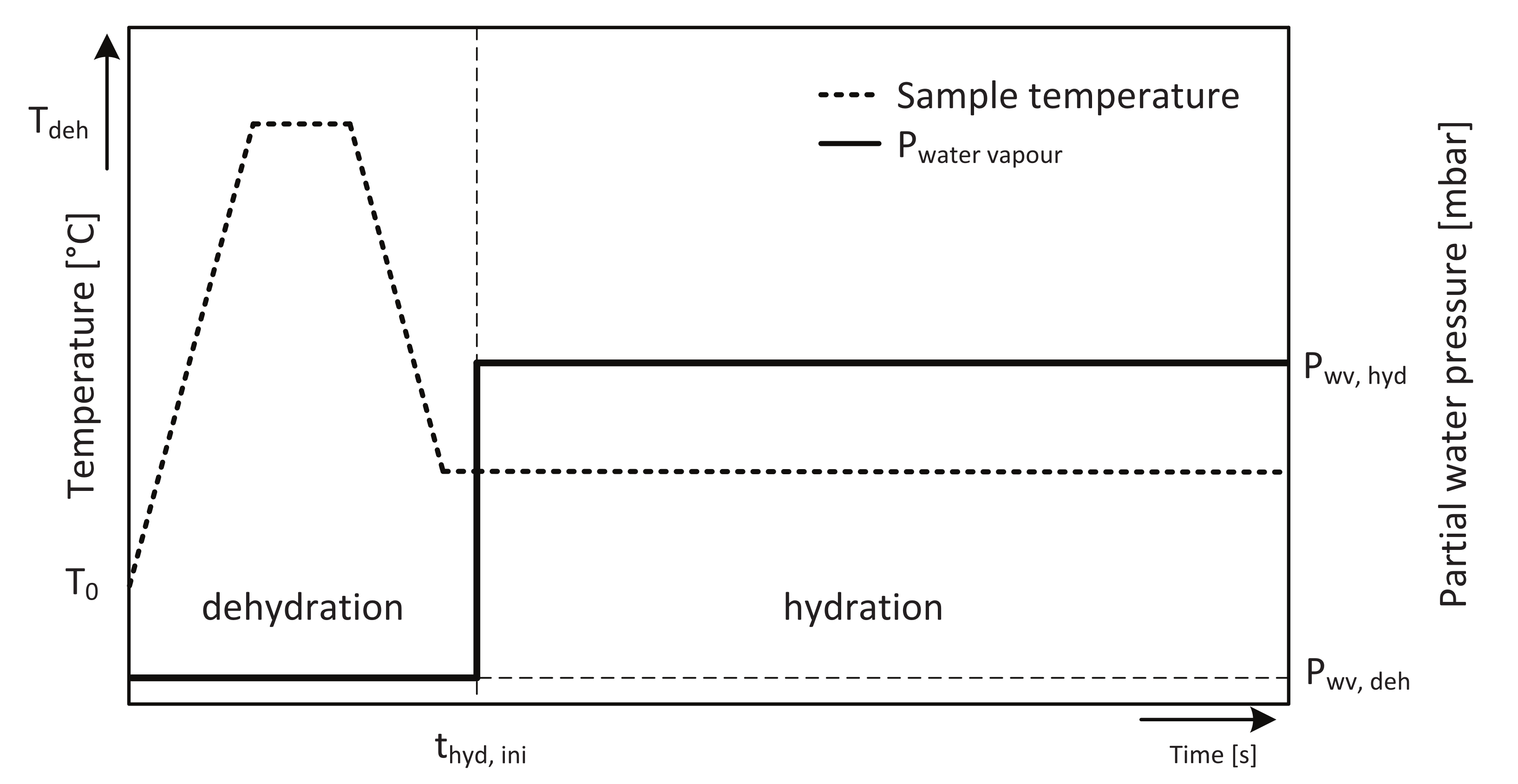
A thermal bath at 25 C ensures that the balance of the STA is kept at isothermal conditions at all times. The STA is calibrated before use. A modular humidity generator (MHG ProUmid) connected to the STA is used to supply water vapor to the sample. The humidifier uses an adjustable flow rate of dry air as a carrier gas. A flow of liquid water from a water reservoir is combined with a flow of dry air in a mixing chamber. The flow coming from the mixing chamber is a constant air stream with a set partial water pressure. The flow rate of humidified air can be set from 0 to 450 mL/min. The humidified air stream in the STA furnace flows from top to bottom through the furnace, directly on top of the sample crucibles. A typical STA run is schematically displayed in Figure 3. To start a measurement with a dry sample, the prepared batch of mechanically pulverized K 2 CO 3 is dehydrated and stored in a sealed container prior to a measurement. After taking a small sample from this container, it is loaded quickly (less than 1 min exposure to environmental air) in the STA furnace, while a constant stream of dry air from the humidifier is flowed through the furnace. This minimizes the amount of water that the sample can absorb prior to the measurement.
First, the K 2 CO 3 sample is heated from the environmental temperature T 0 to T d e h = 120 C, with a heating rate of 1 K/min. This is followed by an isothermal to ensure complete dehydration of the sample. Typically, this isothermal lasts for 1 h, which is enough to fully dehydrate the sample. Next, the sample is cooled down to 40 C with a cooling rate of 1 K/min. A stabilization period of 40 min following the cooling process ensures an isothermal sample with a temperature of 40 C. After the stabilization period, the water vapor is increased from P w v , d e h = 0.2 ± 0.2 mbar to P w v , h y d = 12 ± 0.2 mbar, at time t h y d , i n i . This initiates the hydration reaction of the sample. Typically, the sample is hydrated for 120 min, during which the conversion factor is measured from (3) or (4).

4. Results and Discussion

4.1. Flow Rate Dependency

Since water transport from the humidifier to the sample can be a hydration-limiting process [16], the effect of the moist air flow rate on the hydration time of K 2 CO 3 is investigated by STA. The average hydration time is defined as the time it takes to hydrate a sample from α = 0.05 to α = 0.95. The experimental procedure is shown schematically in Figure 3. Samples are taken from the large batch and loaded in the STA.
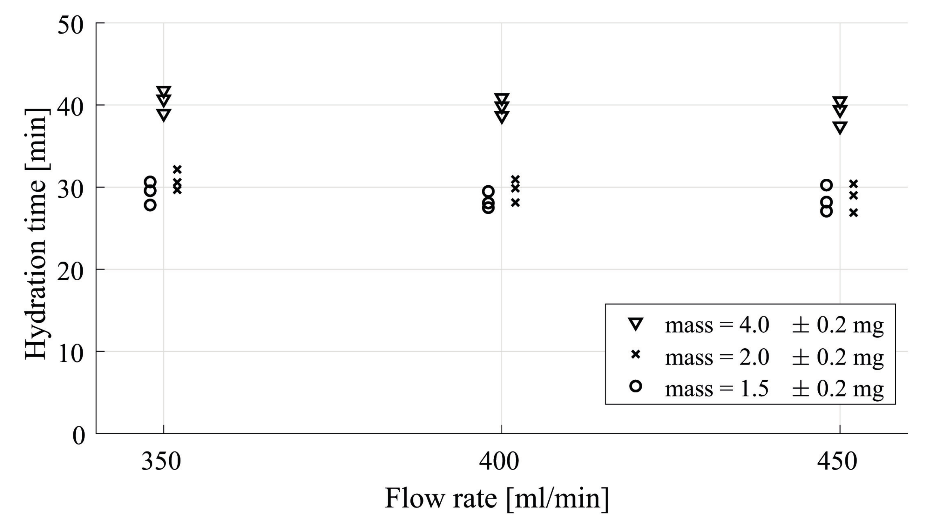
Hydration measurements are performed using three different sample masses: 4.0 mg, 2.0 mg and 1.5 mg. Different sample masses are used to exclude the effect the powder bed thickness has on the hydration time. The water partial pressure is set to 12 mbar, and the flow rate is set to 350, 400 or 450 mL/min at all three sample masses. For each measurement, a new sample was taken from the large batch. The average hydration time was measured three times at each flow rate. The hydration time is evaluated using the DSC signal ( α Q ( t ) , Equation (4)). The result is displayed in Figure 4.
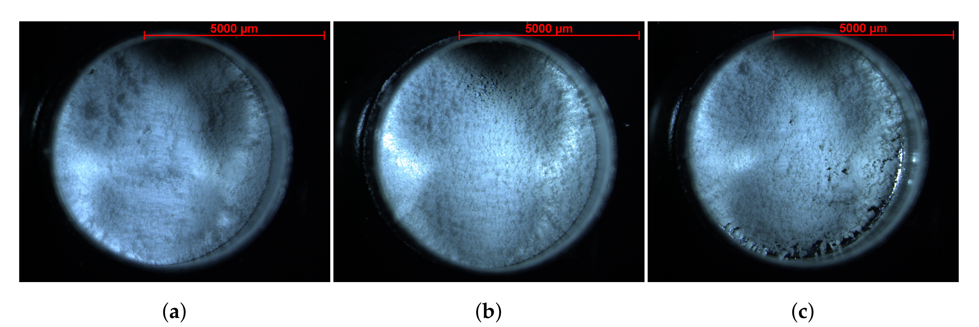
Figure 4 shows that a sample mass of 4.0 mg results in a constant hydration time of approximately 40 min. This hydration time is independent of the flow rate. However, decreasing the sample mass from 4 to 2 mg shows a decrease in hydration time from 40 to about 30 min. Further reduction in the sample mass from 2.0 to 1.5 mg does not decrease the hydration time. Additionally increasing the flow rate from 350 to 450 mL/min does not affect the hydration time, indicating that particle hydration is not hindered by the inter-particle flow. This highlights the importance of the powder bed thickness, which can strongly affect kinetic curves [14,43,44,45]. Figure 5 shows the powder beds in the STA crucibles for the three different measured sample masses.
It is observed that the 4.0 mg sample (Figure 5a) has significantly more K 2 CO 3 powder in the crucible than the 2.0 and 1.5 mg sample masses. The powder bed thickness is estimated using an average particle diameter of 36 μ m, a particle density of 2.43 mg mm 3 , and the crucible surface area of 28 mm 2 . A single layer of approximately 28,000 particles completely covers the bottom surface of the crucible. The estimated number of particles in the crucible for each measured sample mass is shown in Table 1.
It is observed from Table 1 that the 4.0 mg sample consists of well over two particle layers in the STA crucible. The water vapor needs to diffuse through at least one layer before reaching the second layer of particles. This makes the bottom layer of particles less accessible to water vapor and, therefore, the overall hydration time is increased for thicker powder beds. The 2.0 and 1.5 mg samples are estimated to have a bed thickness of approximately one layer. The 1.5 mg sample has a layer thickness of 0.89. This means that there are ‘holes’ in the powder bed, which is also observed from Figure 5c. A layer of approximately one-particle thickness ensures that the water vapor does not need to diffuse through multiple particle layers. This results in a faster hydration time. This is supported by the data shown in Figure 4. In this study, water transport to the particles is excluded as a possible limit for the hydration rate by making sure the particle bed is only one layer thick (the sample mass is 1.5 ± 0.2 mg) in combination with a high flow rate of 450 mL/min.
The hydration of K 2 CO 3 was recently studied by Sögütoglu et al. [16]. Crucibles were used with a surface area of approximately 28 mm 2 , similar to the crucible area used in this work. The authors used 50–164 μ m particles and a sample mass of approximately 5 mg, so the crucibles in their study contained 3.3 particle layers. This is an important difference with this study. The authors concluded that for their case, the hydration limitation is water diffusion to the particle surface.

4.2. Pseudo-Steady State Assumption

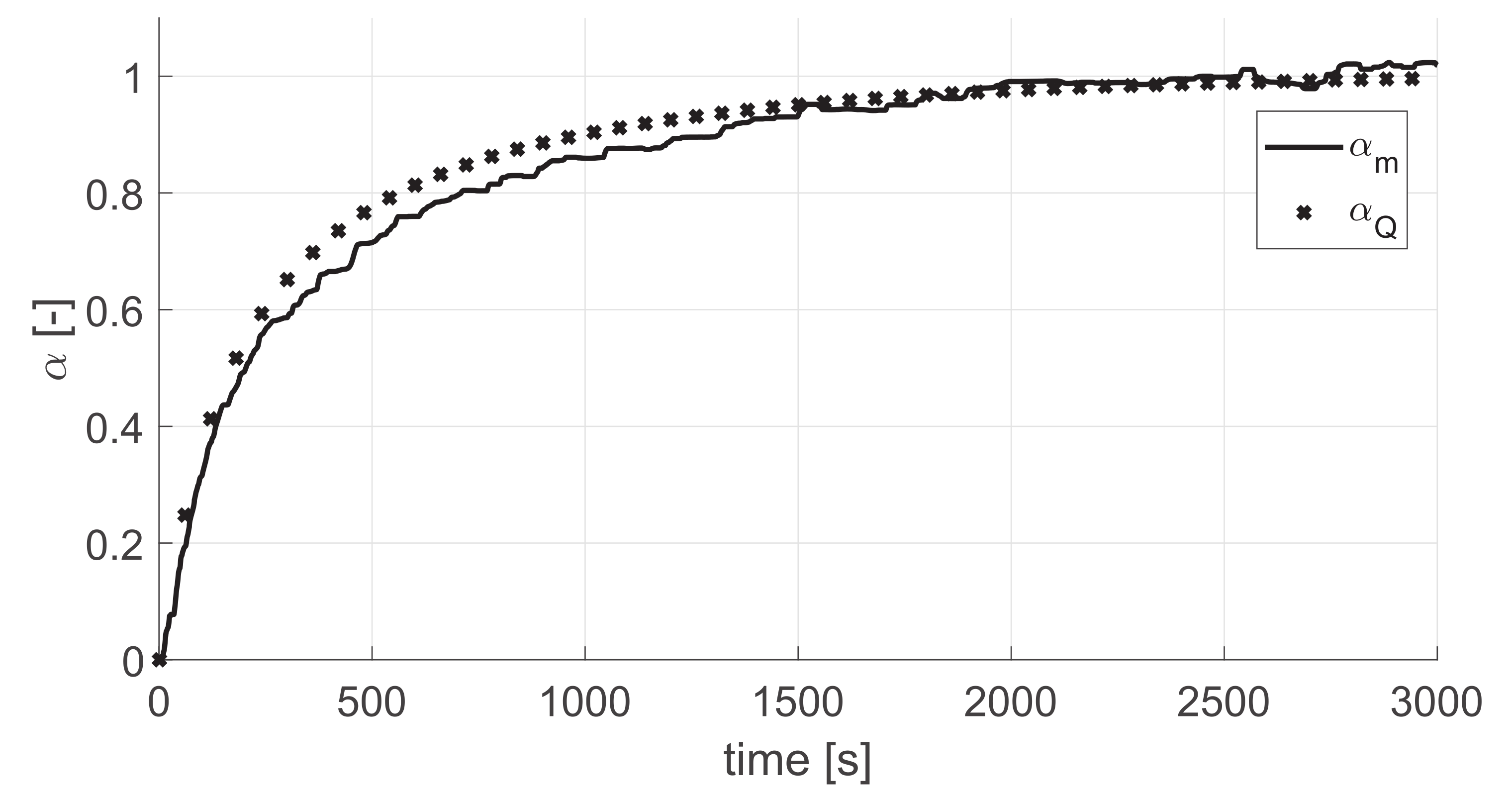
One of the requirements to accurately describe the hydration reaction using Equation (2) is that there should be no accumulation of intermediate species. The reaction should be in a pseudo-steady state [19,24,46,47]. During a pseudo-steady hydration reaction, the heat released during the reaction is linearly related to absorbed water. To investigate the pseudo-steady state assumption, four K 2 CO 3 samples of 1.5 ± 0.2 mg are taken from the large batch. The measurement procedure and conditions are similar to Section 3.2. The hydration conversion was determined using TGA (Equation (3)) and DSC (Equation (4)). A reaction is in a pseudo-steady state if α m ( t ) α Q ( t ) [24]. The result of the pseudo-steady state check is displayed in Figure 6.
It is observed from Figure 6 that within experimental accuracy α m ( t ) = α Q ( t ) and, therefore, the hydration reaction indeed occurs in a pseudo-steady state. This satisfies the first requirement for the use of Equation (2).

4.3. RDS Assumption—Jump Experiments

The second requirement for the use of Equation (2), is that there should be a rate-determining step throughout the complete hydration reaction. To validate this, so-called ‘jump experiments’ are performed. During these experiments, the temperature or the partial water pressure is suddenly changed [18,19,22,24]. Jump experiments can be employed to perform two different tests: the ‘ ϕ S m -test’ and the ‘ f ( α ) -test’.

4.3.1. The ‘ ϕ S m -Test’

The ϕ S m -test can be employed to check whether the complete hydration reaction can be described using a RDS [19,22,23,39,46,47,48]. The test is performed by performing jump experiments by changing the temperature or pressure at different α . The reaction rate before and after the jump is then determined. If the ratio of the reaction rates after ( R a ) and before ( R b ) the jump is identical, then the elementary step controlling the reaction rate is the same during the complete transformation. If the jump is executed fast enough, the S m term is eliminated and the ratio R a b becomes
R a b = R a R b = d α d t a d α d t b = ϕ ( T h y d , b , P w v , a ) S m ( t i n i , j u m p ) ϕ ( T h y d , b , P w v , b ) S m ( t e n d , j u m p ) ϕ ( T h y d , b , P w v , a ) ϕ ( T h y d , b , P w v , b ) .
If the ratio R a b is constant for various α , then Equation (7) is valid [24].
In this paper, a jump in partial pressure is imposed. The jump procedure is visualized in Figure 7. A sample of 1.5 ± 0.2 mg is taken from the large batch and dehydrated for 60 min at 120 C and P w v , d e h = 0.2 ± 0.2 mbar. After dehydration, the sample is cooled down to T h y d = 40 C, and the partial water pressure is kept stable at 2 ± 0.1 mbar to prevent hydration. At a time indicated by symbol x in Figure 7, the hydration is initiated by increasing the partial water pressure to 10 mbar. This is reached at the time indicated by symbol o in Figure 7. From this moment, the hydration starts. After a certain hydration duration, the jump is initiated at symbol □ in Figure 7, corresponding to a certain conversion α by suddenly increasing the partial water pressure from 10 ± 0.1 mbar to 12 ± 0.2 mbar. This jump in partial water pressure takes approximately 30 s. Here, the jump is at t = 540 s. The jump is started at 10 mbar and 40 C to ensure that the hydration reaction is ongoing. Reaction 1 is shifted completely to the right, so the sesquihydrate is being formed. Jumping from 10 to 12 mbar at 40 C ensures that the jump takes place when the particles are hydrated. The jump ends at symbol ∇.
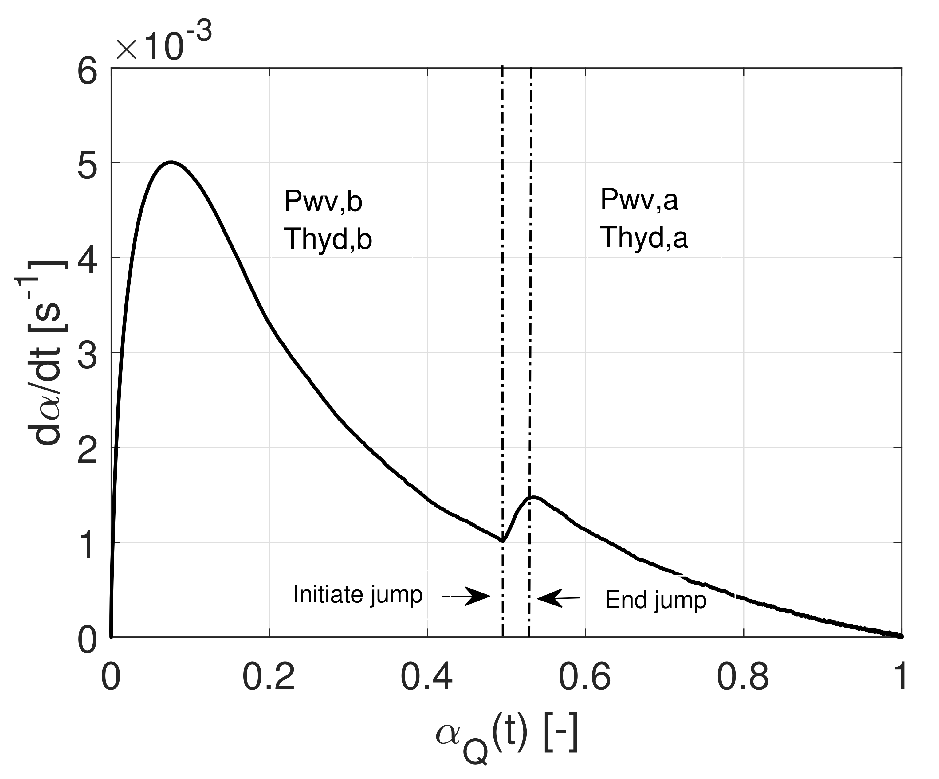
A relatively small jump of 2 mbar is chosen because the jump needs to be large enough to be able to measure the change in hydration rate, but small enough to make the jump fast. The reaction rate as a function of the conversion for a typical jump experiment is displayed in Figure 8, which corresponds to the jump procedure presented in Figure 7.
We start with d α d t = 0 at t = 300 s. The reaction rate increases, peaks at less than 10% conversion when the partial water pressure has reached 10 mbar, and gradually decreases afterwards. At t = 540 s and α = 0.45, the jump is initiated causing d α d t to increase again. From the plot, we notice that the ratio R a b is approximately 1.5 in this case.
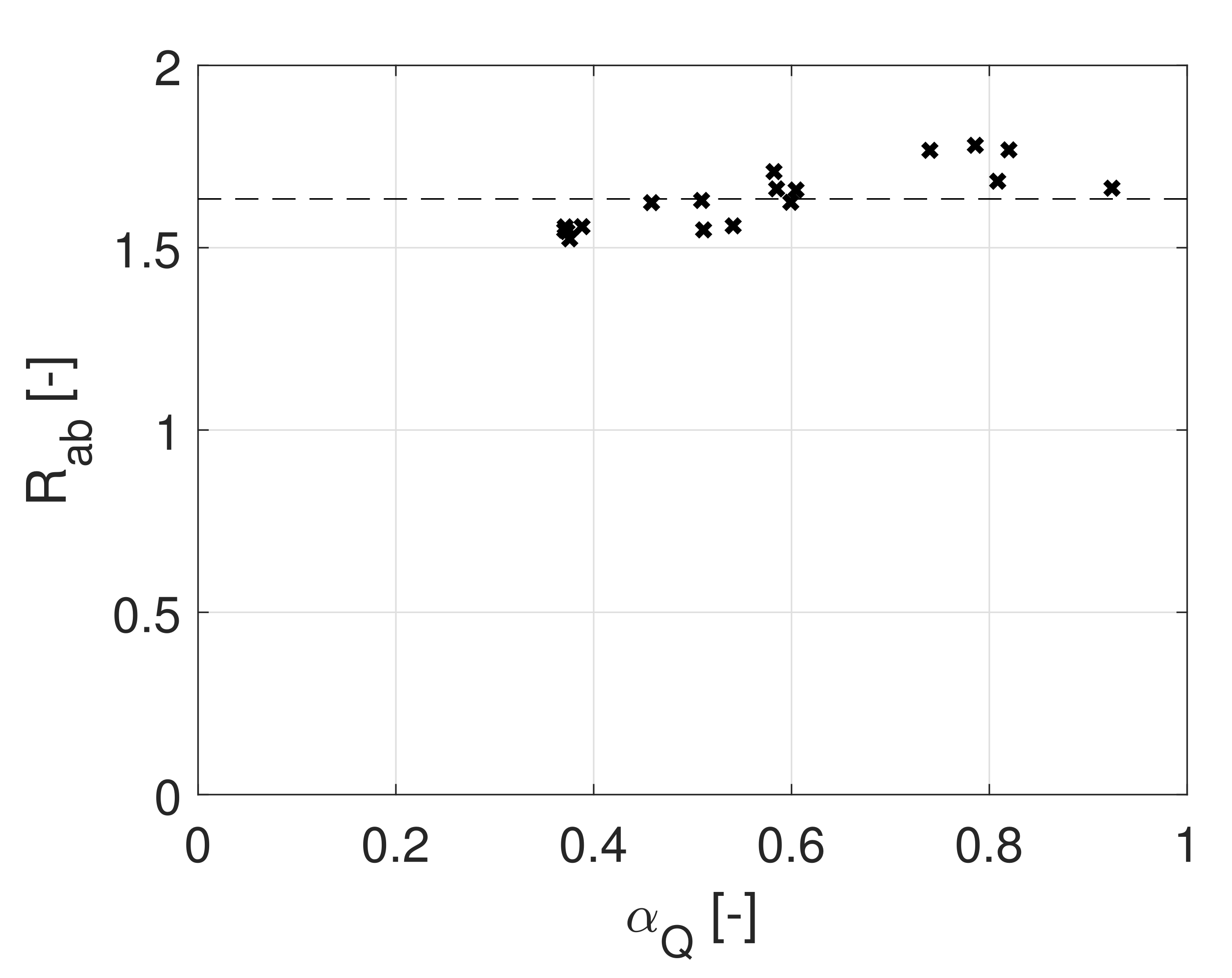
Several jump experiments are performed at multiple α Q . Jumps at different values α Q are obtained by allowing the sample to hydrate longer before initiating the jump. During the 30 s jump duration, the conversion is already affected by the change in partial water pressure before the end of the jump is reached. Ideally, the jump is made instantaneously, but due to the experimental setup limitations, this is not possible. The jump duration is 7–8 times smaller than the time of hydration it takes to reach 50% conversion. Therefore, reliable results can be achieved as the hydration reaction progresses to larger values of α .
Figure 9 displays the results from experiments at 40 C, and jumping from a partial water pressure of 10 to 12 mbar. It is observed that for 0.37 ≤ α ≤ 0.92, R a b is approximately constant. It is concluded that the hydration reaction of K 2 CO 3 can be described using a RDS. This meets the second condition for the use of Equation (2).

4.3.2. The ‘ f ( α ) -Test’

A second test that employs jump experiments is the so-called ‘ f ( α ) -test’ [18,22,23,39,46,48]. With this test, one can determine if the hydration reaction rate can be described using a one-process model (instantaneous nucleation), or if a two-process model (nucleation and growth are simultaneously active) is required.
The f ( α ) -test is executed by performing two experiments at 40 C using a flow rate of 450 mL min 1 and a sample mass of 1.5 ± 0.2 mg. In the first experiment (the one without a jump), a partial pressure of 12 mbar is applied. The second experiment is performed at a partial pressure of 10 mbar, and after a certain moment, a jump is made to 12 mbar. If the conversion rate, after jumping from 10 to 12 mbar, overlaps the curve where no jump is performed, a one-process model can be used to describe the reaction, and Equation (2) can be used.
Figure 10 shows the results of the f ( α ) -tests. The grey curve shows the conversion rate at T h y d = 40 C and P w v , h y d = 12 mbar without jumps. The initial conditions of the four black curves are T h y d = 40 C and P w v , h y d = 10 mbar. At four different α values, the partial water pressure is rapidly increased from 10 to 12 mbar. We note that all black curves catch up with the grey curve sooner or later.
We conclude that not only is there a rate-determining step as previously discussed, but also this RDS is only a function of α as given in Equation (2).

4.4. Modeling

In this section, it is further investigated if a one- or two-process numerical model should be used to describe the hydration reaction of K 2 CO 3 . This is done by fitting a numerical model to experimentally obtained data. The particles in the model are assumed to be perfect spheres with a homogeneous particle size distribution, similar to the large sample batch (Figure 2). The particle radius ranges from D m i n = 22 μ m to D m a x = 46 μ m. The molar volume V m A of dry K 2 CO 3 is 6.0352 × 10 5 [m 3 mol 1 ].
The model is fitted on the experimental data by using the optimization tool ‘fminsearch’ in MATLAB. The experimental data is obtained by averaging the conversion of 6 complete hydration reactions, performed at P w v , h y d = 10 mbar and T h y d = 40 C. The coefficient of determination R 2 is used to assess the accuracy of the fitted model.

4.4.1. One-Process Model—Instantaneous Nucleation Limited by Diffusion

First, a one-process diffusion model is used to describe the hydration conversion of K 2 CO 3 . The D3 diffusion model (Equation (8)) is employed and the difference between the experimental data and the model is minimized by fitting the areic growth rate ϕ . The result is displayed in Figure 11:
Figure 11 shows the hydration conversion α versus time using a one-process diffusion-limited model. The model is compared to an STA measurement. Both numerically and experimentally obtained values of α are compared. It is observed from Figure 11 that the fit of the D3 model to the experimental data is particularly good, resulting in an R 2 of 0.9872. The model underestimates the experimentally obtained conversion slightly from 200 to 800 s. Afterward, it slightly overestimates the conversion from 800 to 5000 s.

4.4.2. Two-Process Models—Simultaneous Nucleation and Growth

For completeness, we also investigate simultaneous nucleation and growth. We chose to solve the isotropic two-process model (Equation (9)) by the method as explained in the work of Helbert et al. and Favergeon et al. [21,49]. Their approach is adopted in this work. At the start of the simulation, nucleation is initiated at the surface of the K 2 CO 3 particles. Nucleation is assumed to follow a space–time Poisson distribution with a mean areic frequency λ , applied in a similar way to the work of Helbert et al. [49]. Nuclei appear on the surface and grow deterministically and isotropically toward the center of the particles. The main advantage of modeling this way is that the model can be applied to any geometrical particle shape.
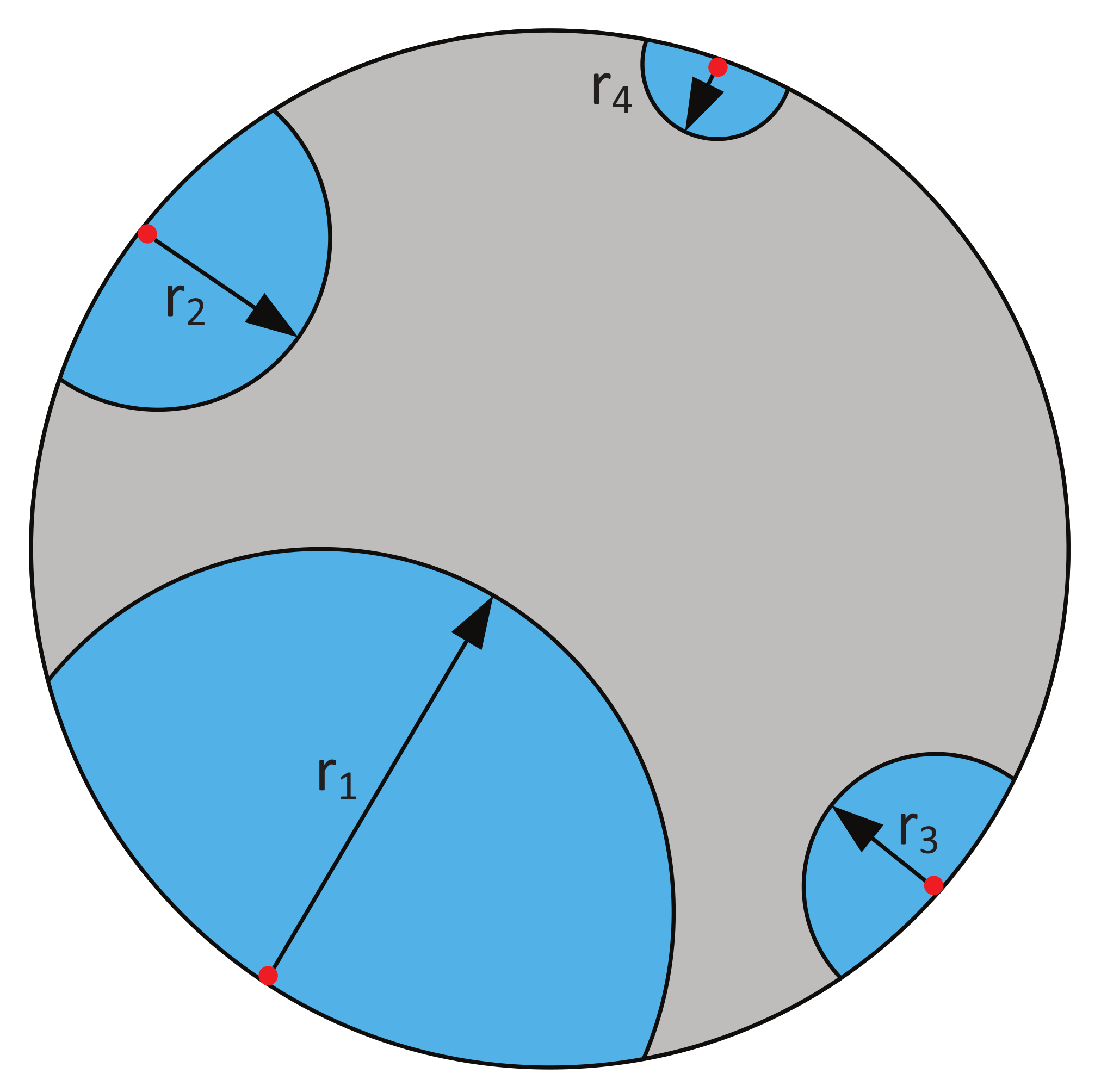
In the case of diffusion-limited growth, the diffusion of water through the hydrated K 2 CO 3 layer into the particles limits the conversion rate. Numerical models are employed to calculate the penetration depth by each formed nuclei at time t. The penetration depth r i ( t , τ i ) [m] by the nuclei’s diffusion-limited growth (see Figure 12) into the particle at time t is given by [42]
r i ( t , τ i ) = D ( t τ i ) for t > τ i .
with τ i the birth time of the ‘ith’ nuclei formed on the particle surface. The difference between experimental data and the model is minimized by fitting the diffusion coefficient D [m 2 s 1 ] and the nucleation rate γ .
The conversion of a single particle α p is calculated based on the ratio of transformed over original K 2 CO 3 . The conversion of multiple particles is determined by incorporating the particle size distribution (Figure 2) as a weight function using the volume of the individual particles [49]. The modeled hydration conversion is then given by
α ( t ) = 1 V t o t p = 1 p t o t V p α p ( t ) ) ,
with V t o t the total volume of all particles [m 3 ], V p the volume of particle p [m 3 ], and p t o t the total number of simulated particles.
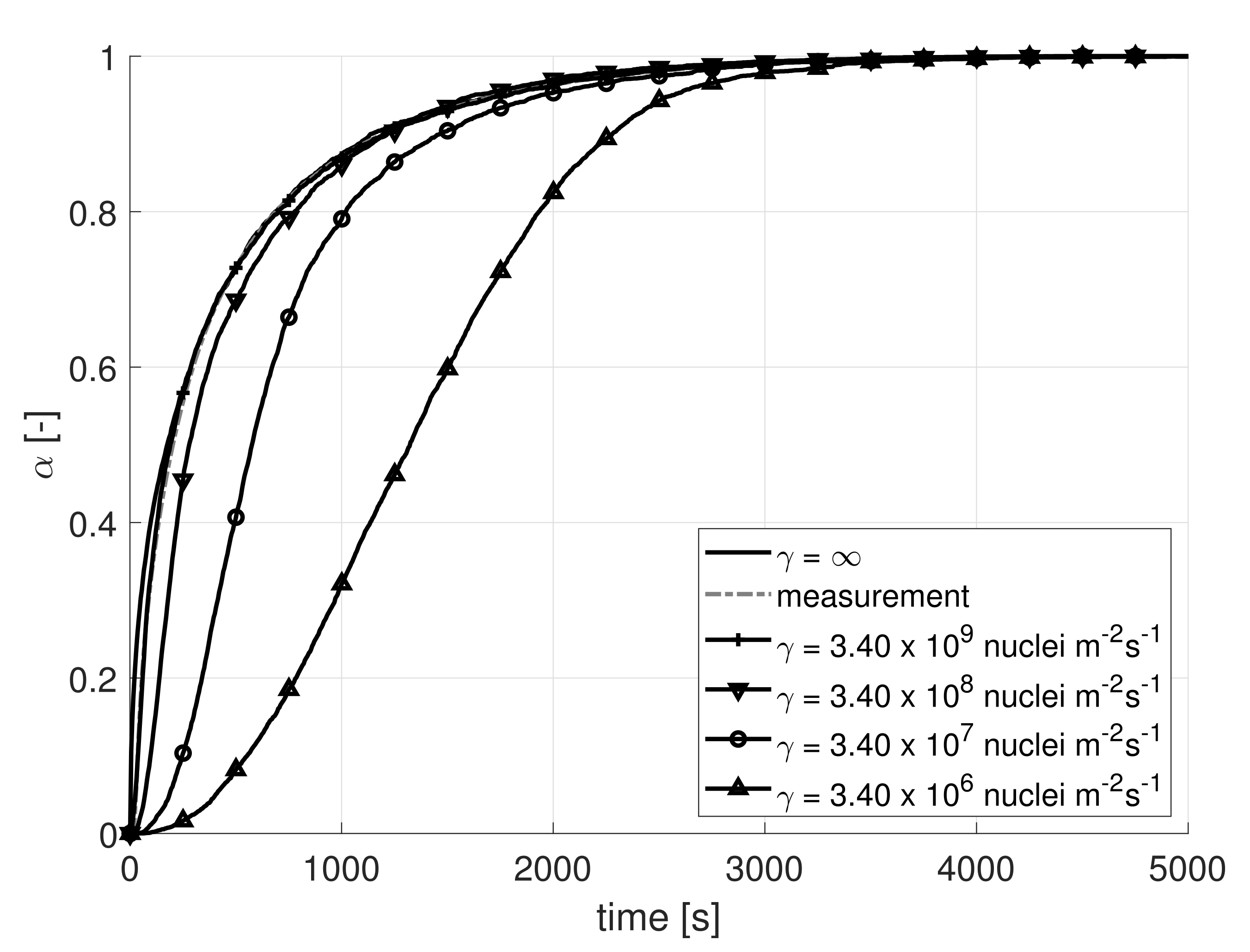
The two-process diffusion-limited model is compared to the experimental data. For the penetration depth, Equation (11) is employed. The model is optimized for the diffusion coefficient D and the nucleation rate γ . The result is shown in Figure 13.
It is observed that the two-process diffusion-limited model almost perfectly fits the experimentally obtained hydration conversion of K 2 CO 3 for the optimized values D = 9.80 × 10 14 m 2 s 1 and γ = 3.40 × 10 9 nuclei m 2 s 1 . For these values, an R 2 of 0.9997 is found. To see the effect of the nucleation rate on the conversion α , the optimized diffusion coefficient D = 9.80 × 10 14 m 2 s 1 is kept constant, and the nucleation rate is changed by one order of magnitude from γ = 3.40 × 10 6 nuclei m 2 s 1 to γ = 3.40 × 10 9 nuclei m 2 s 1 . For each nucleation rate, the hydration conversion is calculated and also displayed in Figure 13. It is observed that the higher the nucleation rate, the more the modeled conversion curve moves to the experimentally obtained curve. It is also observed that for lower nucleation rates, the S-shape of the modeled conversion curve becomes evident. This S-shape is typical for conversions of a material where both nucleation and growth processes are simultaneously active.
Finally, the nucleation rate is set to γ = , and the diffusion coefficient is optimized to fit the experimental data. This results in D = 7.18 × 10 14 m 2 s 1 . It is observed that for infinitely high values of γ (instantaneous nucleation), the model is in excellent agreement with the measurement data. The differences between the curve for γ = 3.40 × 10 9 nuclei m 2 s 1 and the curve of γ = and the experimental data are very small. The diffusion coefficient of 7.18 × 10 14 m 2 s 1 translates to the same growth rate obtained in Figure 11 using ϕ = D r m e a n V m A , with r m e a n the mean particle radius [m]. This proves that the isotropic diffusion-limited model reduces to the D3 model for instantaneous nucleation.
This confirms that the hydration of K 2 CO 3 is governed by instantaneous nucleation and can be described using a one-process model. It is concluded that the hydration reaction of K 2 CO 3 at P w v , h y d = 12 mbar and T h y d = 40 C is governed by instantaneous nucleation and diffusion-limited growth. The results in Section 4.2 show that the hydration reaction of K 2 CO 3 happens in a pseudo-steady state. The results from Section 4.3 show the existence of a RDS. Together with the observation that the hydration can indeed be described using a one-process model, this proves that Equation (2) is valid to describe the hydration reaction of K 2 CO 3 at P w v , h y d = 12 mbar and T h y d = 40 C.
The effect of cycling on the hydration is not investigated in this work. In our previous work [42], we showed that the hydration rate of K 2 CO 3 particles increases over multiple charge and discharge cycles due to crack formation and volume increase in the salt hydrate particles. We showed that this behavior is captured well by a one-process diffusion-limited model in which crack formation is included.

5. Conclusions

This paper aims to improve the understanding of the hydration reaction of K 2 CO 3 . It is investigated if the hydration reaction can be described using the commonly used ‘Arrhenius-f( α )’ equation. To this end, the hydration of K 2 CO 3 particles is investigated by STA experiments and nucleation and growth models.
It is shown that the hydration time is independent of the flow rate for a sample mass of less than 2 mg and at flow rates higher than 350 mL/min. The hydration temperature is 40 C, and the partial water pressure P w v , h y d is 12 mbar. The powder bed thickness should be at maximum one-particle-layer thick to make sure water vapor transport toward the particles is not limiting the reaction.
A comparison of TGA data ( α m ) and DSC data ( α Q ) shows that the hydration of K 2 CO 3 happens at a pseudo-steady state. There is no significant buildup of intermediate species. This satisfies the first requirement for the use equation of the ‘Arrhenius- f ( α ) ’ equation.
So-called ‘jump experiments’ are performed at a constant hydration temperature of T h y d = 40 C. The partial water pressure is rapidly changed from 10 to 12 mbar during these experiments. The results show the existence of a rate-determining step for 0.37 ≤ α ≤ 0.92. This satisfies the second requirement for the use of the ‘Arrhenius- f ( α ) ’ equation.
A one-process diffusion-limited model (D3) was used to model the conversion of the hydration reaction. This model implicitly assumes instantaneous nucleation. A good agreement between the model and the experiment was found.
Next, an isotropic two-process model was considered in which both nucleation and diffusion-limited growth were simultaneously active. The main advantage of this model is that it is applicable to any geometrical particle shape. The two-process model reduces to a once-process model at γ = . At this γ , an excellent agreement with the measurement data was found. Therefore, it is concluded that the hydration reaction can indeed be described using instantaneous nucleation and diffusion-limited growth. This satisfies the third and final requirement to use Equation (2) to describe the hydration reaction at T h y d = 40 C and P w v , h y d = 12 mbar, and leads to the general conclusion that the hydration reaction of K 2 CO 3 particles can be modeled by a one-process model, such as the ‘Arrhenius- f ( α ) ’ equation.

Author Contributions

Conceptualization, M.B. and P.D.; methodology, M.B. and J.R.; software, M.B., J.R. and A.F.; validation, M.B. and J.R.; formal analysis, M.B. and J.R.; investigation, M.B., J.R. and P.D.; resources, M.B.; data curation, M.B. and J.R.; writing—original draft preparation, M.B., A.F., C.R. and D.S.; writing—review and editing, M.B., P.D., A.F., C.R. and D.S.; visualization, M.B. and J.R.; supervision, P.D., A.F., C.R. and D.S.; funding acquisition, D.S. All authors have read and agreed to the published version of the manuscript.

Funding

The authors acknowledge the financial support from ADEM, a green deal in energy materials program of the Ministry of Economic Affairs of The Netherlands (www.adem-innovationlab.nl, accessed on 10 March 2022).

Institutional Review Board Statement

Not applicable.

Informed Consent Statement

Not applicable.

Data Availability Statement

Not applicable.

Acknowledgments

The authors would like to thank Natalia Mazur for assisting with the sample preparation.

Conflicts of Interest

The authors declare no conflict of interest.

References

  1. United Nations Climate Change. The Paris Agreement: Essential Elements. Available online: https://unfccc.int/process-and-meetings/the-paris-agreement/the-paris-agreement (accessed on 20 December 2019).
  2. Quadrelli, R.; Silva, M.; Park, J.; Garcia, V. Energy Efficiency Indicators—Highlights; IEA Publications: Paris, France, 2019. [Google Scholar]
  3. Rindt, C.; Lan, S.; Gaeini, M.; Zhang, H.; Nedea, S.; Smeulders, D.M. Phase change materials and thermochemical materials for large-scale energy storage. In Continuous Media with Microstructure 2; Springer: Eindhoven, The Netherlands, 2016; pp. 187–197. [Google Scholar]
  4. Jänchen, J.; Ackermann, D.; Stach, H.; Brösicke, W. Studies of the water adsorption on zeolites and modified mesoporous materials for seasonal storage of solar heat. Sol. Energy 2004, 76, 339–344. [Google Scholar] [CrossRef]
  5. N’Tsoukpoe, K.E.; Schmidt, T.; Rammelberg, H.U.; Watts, B.A.; Ruck, W.K. A systematic multi-step screening of numerous salt hydrates for low temperature thermochemical energy storage. Appl. Energy 2014, 124, 1–16. [Google Scholar] [CrossRef]
  6. Donkers, P.; Sögütoglu, L.; Huinink, H.; Fischer, H.; Adan, O. A review of salt hydrates for seasonal heat storage in domestic applications. Appl. Energy 2017, 199, 45–68. [Google Scholar] [CrossRef]
  7. N’tsoukpoe, K.E.; Liu, H.; Le Pierrès, N.; Luo, L. A review on long-term sorption solar energy storage. Renew. Sustain. Energy Rev. 2009, 13, 2385–2396. [Google Scholar] [CrossRef]
  8. Barreneche, C.; Fernández, A.I.; Cabeza, L.F.; Cuypers, R. Thermophysical characterization and thermal cycling stability of two TCM: CaCl2 and zeolite. Appl. Energy 2015, 137, 726–730. [Google Scholar] [CrossRef] [Green Version]
  9. Sögütoglu, L.; Donkers, P.; Fischer, H.; Huinink, H.; Adan, O. In-depth investigation of thermochemical performance in a heat battery: Cyclic analysis of K2COl3, MgCl2 and Na2S. Appl. Energy 2018, 215, 159–173. [Google Scholar] [CrossRef]
  10. Wagman, D.D.; Evans, W.; Parker, V.; Schumm, R.; Halow, I. The NBS Tables of Chemical Thermodynamic Properties: Selected Values for Inorganic and C1 and C2 Organic Substances in SI Units; Technical Report; American Chemical Society: Washington, DC, USA, 1982. [Google Scholar]
  11. Gaeini, M.; Shaik, S.; Rindt, C. Characterization of potassium carbonate salt hydrate for thermochemical energy storage in buildings. Energy Build. 2019, 196, 178–193. [Google Scholar] [CrossRef]
  12. Stanish, M.; Perlmutter, D. Rate processes in cycling a reversible gas-solid reaction. AIChE J. 1984, 30, 56–62. [Google Scholar] [CrossRef]
  13. Stanish, M.; Perlmutter, D. Kinetics and transport effects in the dehydration of crystalline potassium carbonate hydrate. AIChE J. 1983, 29, 806–812. [Google Scholar] [CrossRef]
  14. Favergeon, L.; Morandini, J.; Pijolat, M.; Soustelle, M. A General Approach for Kinetic Modeling of Solid-Gas Reactions at Reactor Scale: Application to Kaolinite Dehydroxylation. Oil Gas Sci. Technol. 2013, 68, 1039–1048. [Google Scholar] [CrossRef] [Green Version]
  15. Fopah Lele, A.; Kuznik, F.; Rammelberg, H.U.; Schmidt, T.; Ruck, W.K. Thermal decomposition kinetic of salt hydrates for heat storage systems. Appl. Energy 2015, 154, 447–458. [Google Scholar] [CrossRef]
  16. Sögütoglu, L.C.; Birkelbach, F.; Werner, A.; Fischer, H.; Huinink, H.; Adan, O. Hydration of salts as a two-step process: Water adsorption and hydrate formation. Thermochim. Acta 2021, 695, 178819. [Google Scholar] [CrossRef]
  17. Michèle, P.; Loic, F.; Michel, S. From the drawbacks of the Arrhenius-f (α) rate equation towards a more general formalism and new models for the kinetic analysis of solid–gas reactions. Thermochim. Acta 2011, 525, 93–102. [Google Scholar] [CrossRef] [Green Version]
  18. Pijolat, M.; Valdivieso, F.; Soustelle, M. Experimental test to validate the rate equation “dα/dt = kf (α)” used in the kinetic analysis of solid state reactions. Thermochim. Acta 2005, 439, 86–93. [Google Scholar] [CrossRef]
  19. Pijolat, M.; Soustelle, M. Experimental tests to validate the rate-limiting step assumption used in the kinetic analysis of solid-state reactions. Thermochim. Acta 2008, 478, 34–40. [Google Scholar] [CrossRef]
  20. Brun, C.; Valdivieso, F.; Pijolat, M.; Soustelle, M. Reduction by hydrogen of Ul3Ol8 into UO2: Nucleation and growth, influence of hydration. Phys. Chem. Chem. Phys. 1999, 1, 471–477. [Google Scholar] [CrossRef]
  21. Favergeon, L.; Pijolat, M.; Valdivieso, F.; Helbert, C. Experimental study and Monte-Carlo simulation of the nucleation and growth processes during the dehydration of Li2SO4·H2O single crystals. Phys. Chem. Chem. Phys. 2005, 7, 3723–3727. [Google Scholar] [CrossRef] [PubMed] [Green Version]
  22. Mansour, M.; Favergeon, L.; Pijolat, M. Kinetic modeling of low temperature oxidation of copper nanoparticles by O2. Thermochim. Acta 2013, 570, 41–50. [Google Scholar] [CrossRef] [Green Version]
  23. Nahdi, K.; Perrin, S.; Pijolat, M.; Rouquerol, F.; Ariguib, N.; Ayadi, M. Nucleation and anisotropic growth model for isothermal kaolinite dehydroxylation under controlled water vapour pressure. Phys. Chem. Chem. Phys. 2002, 4, 1972–1977. [Google Scholar] [CrossRef]
  24. Pijolat, M.; Favergeon, L. Kinetics and mechanisms of solid-gas reactions. In Handbook of Thermal Analysis and Calorimetry; Elsevier: Saint-Étienne, France, 2018; Volume 6, pp. 173–212. [Google Scholar]
  25. Pijolat, M.; Brun, C.; Valdivieso, F.; Soustelle, M. Reduction of uranium oxide U3O8 to UO2 by hydrogen. Solid State Ionics 1997, 101, 931–935. [Google Scholar] [CrossRef]
  26. Rouchon, L.; Favergeon, L.; Pijolat, M. Analysis of the kinetic slowing down during carbonation of CaO by CO2. J. Therm. Anal. Calorim. 2013, 113, 1145–1155. [Google Scholar] [CrossRef] [Green Version]
  27. Sögütoglu, L.C.; Steiger, M.; Houben, J.; Biemans, D.; Fischer, H.R.; Donkers, P.; Huinink, H.; Adan, O.C. Understanding the hydration process of salts: The impact of a nucleation barrier. Cryst. Growth Des. 2019, 19, 2279–2288. [Google Scholar] [CrossRef]
  28. L’vov, B.V. Thermal Decomposition of Solids and Melts: New Thermochemical Approach to the Mechanism, Kinetics and Methodology; Springer Science & Business Media: Budapest, Hungary, 2007; Volume 7. [Google Scholar]
  29. Volmer, M.; Weber, A. Keimbildung in übersättigten Gebilden. Z. Phys. Chem. 1926, 119, 277–301. [Google Scholar] [CrossRef]
  30. Vyazovkin, S.; Burnham, A.K.; Criado, J.M.; Pérez-Maqueda, L.A.; Popescu, C.; Sbirrazzuoli, N. ICTAC Kinetics Committee recommendations for performing kinetic computations on thermal analysis data. Thermochim. Acta 2011, 520, 1–19. [Google Scholar] [CrossRef]
  31. Galwey, A.K.; Brown, M.E. Thermal Decomposition of Ionic Solids: Chemical Properties and Reactivities of Ionic Crystalline Phases; Elsevier: Grahamstown, South Africa, 1999. [Google Scholar]
  32. Khawam, A.; Flanagan, D.R. Solid-state kinetic models: Basics and mathematical fundamentals. J. Phys. Chem. B 2006, 110, 17315–17328. [Google Scholar] [CrossRef] [PubMed]
  33. Risthaus, K.; Bürger, I.; Linder, M.; Schmidt, M. Numerical analysis of the hydration of calcium oxide in a fixed bed reactor based on lab-scale experiments. Appl. Energy 2020, 261, 114351. [Google Scholar] [CrossRef]
  34. Vyazovkin, S.; Schick, C.; Verevkin, S.P.; Heym, F.; Androsch, R.; Hunkel, M.; Steinbacher, M.; Pijolat, M.; Favergeon, L.; Koga, N.; et al. Handbook of Thermal Analysis and Calorimetry; Brown, M.E., Gallagher, P.K., Eds.; Elsevier: Birmingham, AL, USA, 2018; p. 503. [Google Scholar]
  35. Vyazovkin, S. Isoconversional Kinetics. In Handbook of Thermal Analysis and Calorimetry; Elsevier: Birmingham, AL, USA, 2008; Volume 5, pp. 503–538. [Google Scholar] [CrossRef]
  36. Lebrun, M.; Spinner, B. Models of heat and mass transfers in solid—Gas reactors used as chemical heat pumps. Chem. Eng. Sci. 1990, 45, 1743–1753. [Google Scholar] [CrossRef]
  37. Vyazovkin, S. Modern isoconversional kinetics: From misconceptions to advances. In Handbook of Thermal Analysis and Calorimetry; Elsevier: Birmingham, AL, USA, 2018; Volume 6, pp. 131–172. [Google Scholar]
  38. Stengler, J.; Bürger, I.; Linder, M. Thermodynamic and kinetic investigations of the SrBr2 hydration and dehydration reactions for thermochemical energy storage and heat transformation. Appl. Energy 2020, 277, 115432. [Google Scholar] [CrossRef]
  39. Neveux, L.; Chiche, D.; Perez-Pellitero, J.; Favergeon, L.; Gay, A.S.; Pijolat, M. New insight into the ZnO sulfidation reaction: Mechanism and kinetics modeling of the ZnS outward growth. Phys. Chem. Chem. Phys. 2013, 15, 1532–1545. [Google Scholar] [CrossRef] [Green Version]
  40. Perrin, S.; Pijolat, M.; Valdivieso, F.; Soustelle, M. Kinetic study of the effect of a sudden change in temperature during the reduction of U3O8 into UO2 by hydrogen. Solid State Ionics 2001, 141, 109–115. [Google Scholar] [CrossRef]
  41. Favergeon, L.; Pijolat, M.; Soustelle, M. Surface nucleation and anisotropic growth models for solid-state reactions. Thermochim. Acta 2017, 654, 18–27. [Google Scholar] [CrossRef]
  42. Beving, M.; Frijns, A.; Rindt, C.; Smeulders, D. Effect of cycle-induced crack formation on the hydration behaviour of K2CO3 particles: Experiments and modelling. Thermochim. Acta 2020, 692, 178752. [Google Scholar] [CrossRef]
  43. Koga, N.; Tanaka, H. Effect of sample mass on the kinetics of thermal decomposition of a solid: II. Isothermal dehydration of Li2SO4·H2O. J. Therm. Anal. Calorim. 1993, 40, 1173–1179. [Google Scholar] [CrossRef]
  44. Van Essen, V.; Zondag, H.; Gores, J.; Bleijendaal, L.; Bakker, M.; Schuitema, R.; Van Helden, W.; He, Z.; Rindt, C. Characterization of MgSO4 hydrate for thermochemical seasonal heat storage. J. Sol. Energy Eng. 2009, 131, 041014. [Google Scholar] [CrossRef]
  45. Fisher, R.; Ding, Y.; Sciacovelli, A. Hydration kinetics of K2CO3, MgCl2 and vermiculite-based composites in view of low-temperature thermochemical energy storage. J. Energy Storage 2021, 38, 102561. [Google Scholar] [CrossRef]
  46. Surla, K.; Valdivieso, F.; Pijolat, M.; Soustelle, M.; Prin, M. Kinetic study of the oxidation by oxygen of liquid Al–Mg 5% alloys. Solid State Ionics 2001, 143, 355–365. [Google Scholar] [CrossRef]
  47. Tupin, M.; Pijolat, M.; Valdivieso, F.; Soustelle, M. Oxidation kinetics of ZrNbO in steam: Differences between the pre-and post-transition stages. J. Nucl. Mater. 2005, 342, 108–118. [Google Scholar] [CrossRef] [Green Version]
  48. Tupin, M.; Pijolat, M.; Valdivieso, F.; Soustelle, M.; Frichet, A.; Barberis, P. Differences in reactivity of oxide growth during the oxidation of Zircaloy-4 in water vapour before and after the kinetic transition. J. Nucl. Mater. 2003, 317, 130–144. [Google Scholar] [CrossRef] [Green Version]
  49. Helbert, C.; Touboul, E.; Perrin, S.; Carraro, L.; Pijolat, M. Stochastic and deterministic models for nucleation and growth in non-isothermal and/or non-isobaric powder transformations. Chem. Eng. Sci. 2004, 59, 1393–1401. [Google Scholar] [CrossRef]
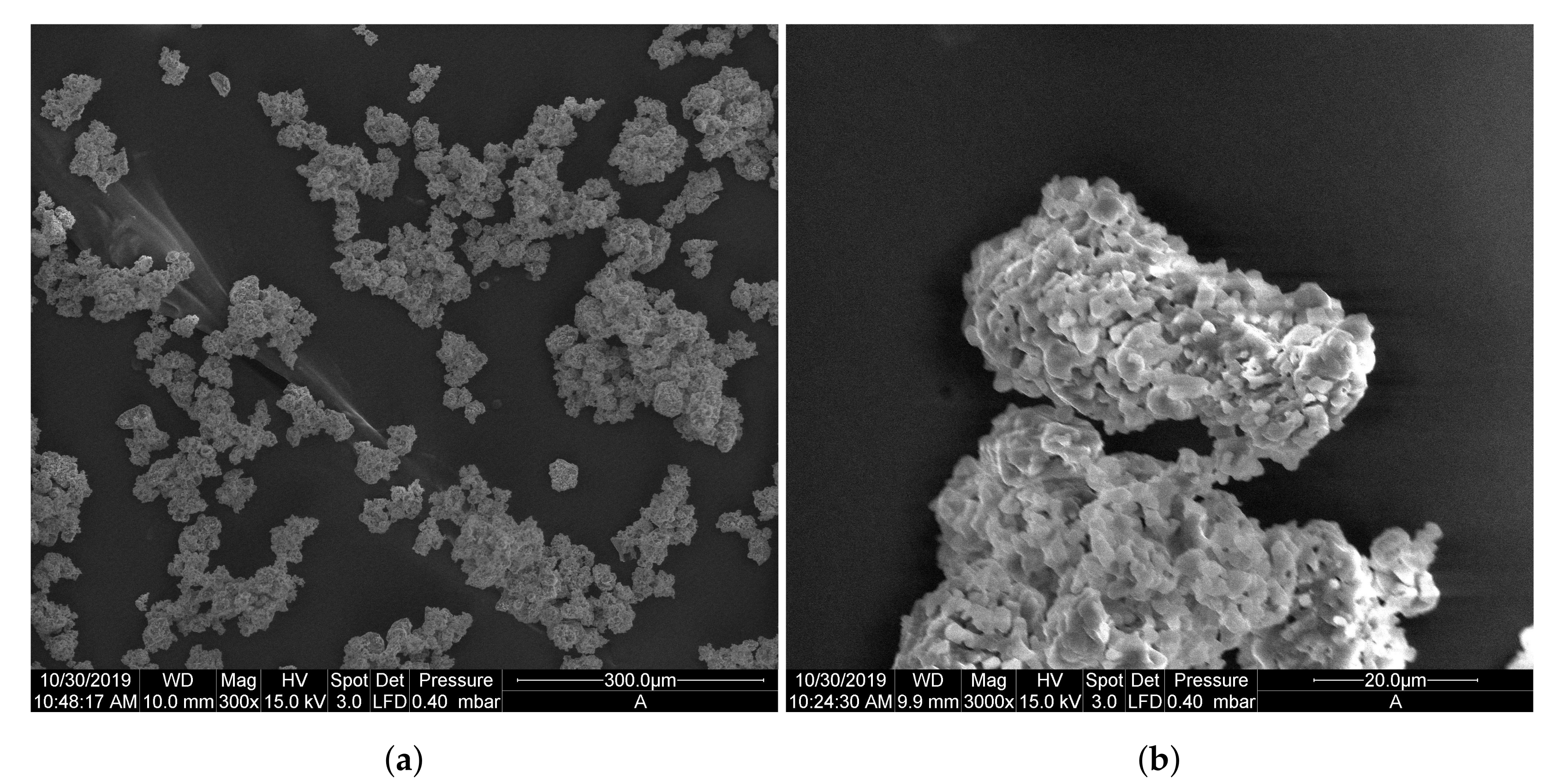
Figure 1. (a) SEM image of the uniform particle batch of K 2 CO 3 particles sieved to have a diameter of 25–38 μ m. (b) Zoom-in of one particle.
Processes 10 00547 g001
Figure 2. The particle size distribution of the uncycled, anhydrous sample batch.
Processes 10 00547 g002
Figure 3. Representation of a typical STA run (not to scale). The partial water pressure is indicated by the solid and dashed lines. The temperature is indicated by the dotted line.
Processes 10 00547 g003
Figure 4. Hydration time for different flow rates and different sample masses. The measurements were executed at a water partial pressure of 12 mbar. The set flow rates were flow rates of 350, 400 or 450 mL/min. Measurements indicated by circles and crosses are shifted slightly horizontally to enhance visibility.
Processes 10 00547 g004
Figure 5. Pictures of the powder bed for a 4.0 mg (a), 2.0 mg (b) and 1.5 mg (c) sample. The pictures were taken with a zoom factor of 19.2 using a Zeiss SteREO Discovery V20 microscope. The dark areas on top are caused by a non-uniform light source.
Processes 10 00547 g005
Figure 6. Validation of pseudo-steady state conditions for T h y d = 40 C and P w v , h y d = 12 mbar.
Processes 10 00547 g006
Figure 7. Representation of a ‘jump experiment’ performed using the STA.
Processes 10 00547 g007
Figure 8. α Q versus the hydration conversion rate for a single jump experiment. P w v , b = 10 mbar, T h y d , b = 40 C. P w v , a = 12 mbar, T h y d , a = 40 C.
Processes 10 00547 g008
Figure 9. Jump ratio R a b as a function of the conversion α Q . The values lie within 10% of the mean (dashed line) value 1.63.
Processes 10 00547 g009
Figure 10. The conversion rate d α /dt as function of α Q for the f ( α ) -test. Y 2 shows the conversion rate at T h y d = 40 C and P w v , h y d = 12 mbar without jumps. Y 1 starts at T h y d = 40 C and 10 mbar, and after a certain moment, the partial pressure is rapidly increased from 10 to 12 mbar, causing a ‘jump’.
Processes 10 00547 g010
Figure 11. The hydration conversion versus time for the one-process diffusion-limited model (D3). Fitting results: ϕ = 6.9975 × 10 5 [mol m 2 s 1 ], R 2 = 0.9872.
Processes 10 00547 g011
Figure 12. Schematic 2D representation of the penetration depth r i that originates from nuclei i, with i = 1:4. Nuclei are indicated with red dots. The blue areas indicate hydrated K 2 CO 3 ; the grey areas indicate anhydrous K 2 CO 3 .
Processes 10 00547 g012
Figure 13. Isotropic diffusion-limited model. The effect of the nucleation rate shown by increasing γ from γ = 3.40 × 10 6 nuclei m 2 s 1 to γ = 3.40 × 10 9 nuclei m 2 s 1 (D = 9.80 × 10 14 m 2 s 1 ). For γ = , the optimized diffusion coefficient becomes D = 7.18 × 10 14 m 2 s 1 . At γ = , all the surface points of the particles are nucleated instantly.
Processes 10 00547 g013
Table 1. Estimated number of particles and particle layers in the crucible.
Sample [mg]# Particles [-]# Layers [-]
4.0∼67,0002.4
2.0∼33,0001.2
1.5∼25,0000.89
Publisher’s Note: MDPI stays neutral with regard to jurisdictional claims in published maps and institutional affiliations.